


WD-VDS
WD-VDS6010
DOUBLE DRAIN VALVE
TECHNICAL/INSTALLATION MANUAL
WD-VDS – WD-VDS6010
INSTALLATION INSTRUCTIONS
2
READ THE INSTRUCTION MANUAL with care
This manual relates to the WD-VDS and WD-VDS6010 accessories, DOUBLE DRAIN VALVES, which are
used to “separate drain outlets”. The kit is composed of two valves with 1½” threaded fittings and
viton membrane; the valves are actuated by the device's controller board.
The system conveys the drain water from the first wash cycles separately from the water from the final
rinse cycles.
The accessory can be installed to the following Smeg devices.
WD-VDS:
WG RANGE - LABORATORY GLASSWARE WASHERS
GW3060
GW4090
GW6090B
GW6290
WD RANGE – HOSPITAL WASHER DISINFECTORS
WD3060
WD5090
WD6090B
WD-VDS6010:
WG RANGE - LABORATORY GLASSWARE WASHERS
GW6010
GW7010
GW7015
WD RANGE – HOSPITAL WASHER DISINFECTORS
WD6010
WD7010
WD7015
The WD-VDS6010 may only be installed to devices equipped with drain pumps (e.g.
DRAINP6010)
The accessory may be ordered together with the device to which it is to be fitted, whether a glassware
washer or washer disinfector, or ordered and installed at a later time.
For proper, safe use, this manual must be used together with the manual of the device (washer
disinfector or glassware washer) on which the accessory is installed.
Failure to read, any misunderstanding or incorrect interpretation of the instructions provided in this
manual may lead to misuse of the device, put the operator at risk and considerably impair the device’s
performance.
The manufacturer declines all liability for uses other than those described in this manual.
Installation, maintenance and repairs must be carried out only by SMEG
authorised staff.
WD-VDS – WD-VDS6010
INSTALLATION INSTRUCTIONS
3
In the event that the device is used in breach of the instructions provided by
SMEG, the manufacturer, the relative warranty rights could be forfeited.
The information in this manual is provided for guidance only. The contents and the equipment
described may be subject to change without notice.
19 390 3492 06
15/07/2019
Rev.
Date
INFORMATION AND AFTER-SALES SERVICE FOR SMEG PRODUCTS
Smeg S.p.A.
Via Leonardo da Vinci, 4
42016 Guastalla – Reggio Emilia - Italy
www.smeg-instruments.com
Italy
• After-Sales Service (Service and Technical Information) contact:
o Single contact number for Italy 0522.184.85.95
o Fax +39 02 38073401
o Email: assistenza.instruments@smeg.it
• For Other Information
o Email: instruments@smeg.it
WD-VDS – WD-VDS6010
INSTALLATION INSTRUCTIONS
4
Table of Contents
1 INTRODUCTION ........................................................................................................................................................... 5
2 SYSTEM CONFIGURATION - TO BE DONE BY THE USER ............................................................................... 5
3 DESCRIPTION OF COMPONENTS ........................................................................................................................... 5
4 INSTALLING THE FIRST BLOCK ............................................................................................................................ 7
5 CONNECTING THE SECOND BLOCK ..................................................................................................................... 8
5.1 CONNECTING THE WD-VDS TO THE GW3060/GW4090 ......................................................................................... 8
5.2 CONNECTING THE WD-VDS TO THE WD5090 ......................................................................................................... 9
5.3 CONNECTING THE WD-VDS TO THE GW/WD6090B AND GW6290 ......................................................................10
5.3.1 GW/WD6090B ................................................................................................................................................... 10
5.3.2 GW6290 ............................................................................................................................................................ 12
5.4 CONNECTING THE WD-VDS6010 TO THE WD/GW 6010-7010-7015 ............................................................13
5.4.1 INSTALLING THE EXTERNAL ACCESSORY JUNCTION BOX .................................................................................. 13
5.4.2 CONNECTING THE WD-VDS6010 ....................................................................................................................... 17
6 HOW TO ENABLE AND TEST THE ACCESSORY ................................................................................................20
6.1 MODELS: GW3060, GW4090 - WD3060, WD5090 – GW6090B, WD6090B ........................................................20
6.2 MODELS: GW/WD6010 – GW/WD7010- GW/WD7015 -GW6290 .......................................................................20
7 WARNINGS FOR USE .................................................................................................................................................20
8 USING THE ACCESSORY ..........................................................................................................................................20
WD-VDS – WD-VDS6010
INSTALLATION INSTRUCTIONS
5
1 INTRODUCTION
The “VDS” (double drain valve) system is used to convey the “polluting solution” discharged by washer disinfectors,
generally water + detergent + biologically contaminated material + miscellaneous residue, into a recovery tank rather than
to the sewers.
The VDS kit separates out the “contaminated” drain water from the first wash cycles from the “clean” drain water.
The VDS is composed of a double valve located on the device’s drain outlet which is controlled directly by the device’s on-
board controller, thus creating two separate drain outlets.
NOTE:
The fittings for connecting the solenoid valve outlets to the drain hoses are not included in the
kit and must be provided by the user.
2 SYSTEM CONFIGURATION - TO BE DONE BY THE USER
Smeg technical staff are not authorised to do any construction work or modifications to the user’s plumbing.
The construction work and modifications required for the installation of the WD-VDS must be done at the user’s expense
by qualified technicians (plumber/fitter):
1. CONSTRUCTION WORK: The two brackets included in the kit must be mounted to the wall with anchor bolts,
40 cm higher than the level at which the device itself is installed, and positioned to allow a slope of 5°-10° to the
horizontal (as specified below). We recommend using the pre-assembled WD-VDS kit to determine and mark the
proper installation position on the wall.
2. PLUMBING: The user is responsible for connecting the two outlets of the WD-VDS kit to the drain circuit. The two
valves (“Recovery” and “Drain”) of which the kit is composed have 1 ½” threaded outlet fittings. We recommend
that the outlet connections be made with:
a. Pipe reduction fittings to connect ¾” hose fittings to the outlets (fittings not included);
b. Rubber drain hoses, ¾” (ID 20 mm) to connect the outlets to the system drain fittings (hoses not
included). The hoses must be rated to handle the maximum water temperature discharged by the device
(95°C), and be of the recommend diameter (ID 20 mm).
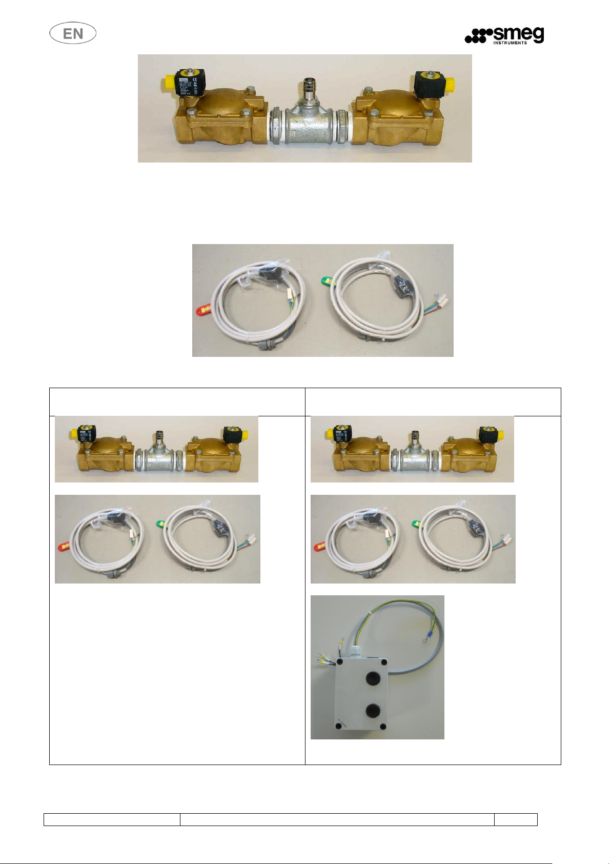
3 DESCRIPTION OF COMPONENTS
We break the VDS system down into 2 blocks to explain how to install it.
The “first block” is composed of:
• N. 2 solenoid operated valves with 1 ½” inlet and outlet fittings. In the following image, the LH valve is the “Drain”
valve, while the RH valve is the “Recovery” valve. The solenoid valves are actuated by the device's controller as
follows:
o The Recovery valve (marked “EVSA”, alternative discharge solenoid valve) intercepts the potentially
contaminated flow resulting from the first phases of the process (prewash, wash, neutralisation).
On models WD6010 and GW6010, this valve is marked EVRS
o The Drain valve “EVU”, intercepts the flow coming from the remaining phases of the cycle.
On models WD6010 and GW6010, this valve is marked EVSL
• N. 1 central “T” fitting (with n. 1 ¾” inlet which accepts a ¾” hose fitting and n 2 1½” outlets)
WD-VDS – WD-VDS6010
INSTALLATION INSTRUCTIONS
6
Figure 1 – VDS kit first block
“Second block”:
• N. 2 power cables with connectors for hooking up the solenoid valves
Figure 2 – VDS kit second block
WD-VDS kit
WD-VDS6010 kit for models:
GW/WD 6010-7010-7015
First block
Second block
First block
Second block
External accessory junction box, included in kits WDVDS6010 and PAD2-6010

WD-VDS – WD-VDS6010
INSTALLATION INSTRUCTIONS
7
4 INSTALLING THE FIRST BLOCK
Follow the installation instructions to ensure the system operates properly.
Install the solenoid valves with their covers uppermost to facilitate cleaning and maintenance.
Install the first block to the wall using the included brackets, as follows:
1. The drain block, EVU, must be located no more than 40 cm higher than the level of the device itself (washer
disinfector/glassware washer).
2. Install the block at a slope of 5° - 10° from the horizontal, with the recovery valve (EVSA) lower than the drain valve
(EVU), to improve the flow of the contaminated solution.
3. Connect the glassware washer/washer disinfector's outlet hose to the hose fitted on the “T” union of the first block
of the VDS system.
Figure 3 – Drain block, detail of bracket.
Figure 4 – Wall mounting bracket for drain block
Figure 5 – Height of drain block above level of
device
Figure 6 – Slope of drain block relative to the horizontal
Figure 7 – Drain block hose fitting for
connection to the device's drain hose
Drain
hose
DRAIN
RECOVERY

WD-VDS – WD-VDS6010
INSTALLATION INSTRUCTIONS
8
5 CONNECTING THE SECOND BLOCK
GENERAL INSTALLATION PRECAUTIONS
Before doing any work: disconnect the power supply using the appropriate switch on the panel or
disconnecting the power cable, and turn off the water intake tap.
CLEARANCE: A clearance of about 1 m2 is required at the front and back of the device to allow
correct operation.
PROTECTIVE EQUIPMENT: Use appropriate personal protective equipment.
5.1 CONNECTING THE WD-VDS TO THE GW3060/GW4090
1. Disconnect the device from its power supply.
2. Go to the back of the device.
3. Undo the RH plate from the rear strut by undoing its 3 screws.
4. Remove the black caps on the plate above the drain hose and install the PG cable glands included with the VDS kit
with their collars.
5. The interior of the RH plate mounts a terminal block marked with the connections for the WD-VDS kit.
6. Connect the cable coming from the “EVSA” (“contaminated”) recovery valve to EVSA and NEVSA, and the cable
coming from the “EVU” (“clean”) drain valve to EVU and NEVU on the white terminal block located above the
drain hose (see images below).
7. Once you have made the connection, make sure that you have not disturbed any other connections, then restore
the RH plate to the rear strut.
8. Connect the solenoid valves to the cables you have just installed:
a. Remove the yellow cap from the solenoid valve to uncover its contacts;
b. Connect the black connector coming from “EVSA” to the recovery valve and secure it with the retainer
screw;
c. Connect the black connector coming from “EVU” to the “clean” drain valve and secure it.
Figure 8 – Rear of device, detail of rear strut
Figure 9 – RH plate on rear strut, detail of
caps to remove when hooking up the kit
Figure 10 – Detail of interior side, RH plate on rear
strut
Figure 11 – Detail of solenoid valve and
connector with retainer screw
Terminal block
for WD-VDS
cable
connections

WD-VDS – WD-VDS6010
INSTALLATION INSTRUCTIONS
9
5.2 CONNECTING THE WD-VDS TO THE WD5090
1. Disconnect the device from its power supply.
2. Go to the back of the device.
3. Release the lower cover from the enclosure by undoing its screws and remove the 2 black caps.
4. The interior of the plate mounts a terminal block marked with the connections for the WD-VDS kit.
5. Connect the cable coming from the “EVSA” (potentially contaminated) recovery valve to EVSA and NEVSA;
6. Connect the cable coming from the “EVU” (clean) drain valve to EVU and NEVU.
7. Check that the connections match the markings on the cables.
8. Once you have made the connection, make sure that you have not disturbed any other components, then restore
the cover.
9. Connect the solenoid valves to the cables you have just installed:
a. Remove the yellow cap from the solenoid valve to uncover its contacts;
b. Connect the black connector coming from “EVSA” to the recovery valve and secure it with the retainer
screw;
c. Connect the black connector coming from “EVU” to the “clean” drain valve and secure it.
Figure 12 – Rear of device, detail of caps to remove when
hooking up the kit.
Figure 13 – Interior side of lower enclosure cover plate, kit
connection terminal block.
Figure 14 – Detail of solenoid valve and connector with
retainer screw
EVSA and NEVSA
EVU and NEVU

WD-VDS – WD-VDS6010
INSTALLATION INSTRUCTIONS
10
5.3 CONNECTING THE WD-VDS TO THE GW/WD6090B AND GW6290
5.3.1 GW/WD6090B
PROCEDURE
IMAGE
1. Disconnect the device from its power supply.
2. Remove the pre-cut tabs from
the rear strut
3. Remove the section of the RH
side panel to access the interior
of the device
4. Insert the cables with their PGs
into the holes in the rear strut
and tighten down the PGs

WD-VDS – WD-VDS6010
INSTALLATION INSTRUCTIONS
11
PROCEDURE
IMAGE
5. The rear strut mounts the
terminal block used to hook up
the kit
6. Connect the cables coming from the Recovery Drain “EVSA” (“EVRS”) (potentially contaminated) valve to terminals EVSA
(EVRS), to Neutral (blue cable) NEVSA and to earth (yellow/green)
7. Connect the cables coming from the free drain “EVU” (“EVSL”) (clean) valve to terminals EVU (EVSL), to Neutral (blue cable)
NEVU and to earth (yellow/green)
8. Check that the connections
match the markings on the
cables themselves.
NB: if the terminal block does
not have an earth terminal, use
a loose terminal
9. Once you have made the connection, make sure that you have not disturbed any other components, then restore the rear
panel.
10. Connect the solenoid valves to
the cables you have just installed:
a. Remove the yellow cap
from the solenoid valve
to uncover its contacts;
b. Connect the black
connector coming from
“EVSA” (or "EVRS") to
the recovery valve and
secure it with the
retainer screw;
c. Connect the black
connector coming from
“EVU” (or "EVSL") to the
“clean” drain valve and
secure it.
Detail of solenoid valve and
connector with retainer screw
11. Restore the section of side panel
Important: downline of the WD-VDS kit, the drain hoses must be positioned as indicated in the device's
user manual

WD-VDS – WD-VDS6010
INSTALLATION INSTRUCTIONS
12
5.3.2 GW6290
PROCEDURE
IMAGE
Remove the right-hand side
panel of the device
Remove the precut tabs on
the strut where the cables
included in the kit are to be
inserted.
Once you have inserted the
cable gland into the strut
and secured the cable,
connect it to the terminal
block as indicated by the
markings:
EXTERIOR
OF DEVICE
INTERIOR
OF DEVICE
CLEAN
DRAIN
EVSL
DRAIN
RECOVERY
EVSR
Connect the solenoid valves
to the cables you have just
installed:
1 - Remove the yellow cap
from the solenoid valve to
uncover its contacts;
2 - Connect the black
connector coming from
“EVSA” (or "EVSR") to the
recovery valve and secure it
with the retainer screw;
3 - Connect the black
connector coming from
“EVU” (or "EVSL") to the
“clean” drain valve and
secure it.

WD-VDS – WD-VDS6010
INSTALLATION INSTRUCTIONS
13
5.4 CONNECTING THE WD-VDS6010 TO THE WD/GW 6010-7010-7015
Note: The optional WD-VDS6010 kit may only be installed to devices equipped with the optional
drain pump (ref. “DRAINP6010” for 6010 and 7010-- ref. ” DRAINP7015” for 7015).
5.4.1 INSTALLING THE EXTERNAL ACCESSORY JUNCTION BOX
PROCEDURE
IMAGE
1. Disconnect the device from its power supply.
2. Go to the front of the device (loading side)
- Open the detergent compartment door “A”
- Undo the 4 screws securing the board
compartment door “B” and open the door (*).
Notes:
(*) For 6010 models, make sure the master
power switch is set to OFF (0), otherwise the
interlock will prevent door from being opened.
3. Pull the board drawer out until it stops
(movement “A” in the figure).
Raise the plastic panel protecting the
components on the right (movement “B” in the
figure).
4. If the device is a single-door unit, remove the
lower panel at the back of the device by
undoing its 4 screws.
If the device has two doors, remove the
unloading side lower panel by undoing its 2
screws as shown in the figure.

WD-VDS – WD-VDS6010
INSTALLATION INSTRUCTIONS
14
5. Now use the external accessory junction box
combined with the WD-WDS6010 kit
6. Open the external accessory junction box and
secure it to the device's LH strut using the
provided screw holes.
Use the 2 included 4MA screws to screw it on

WD-VDS – WD-VDS6010
INSTALLATION INSTRUCTIONS
15
7. Secure the earth cable coming out of the
external accessory junction box to the earth
screw on the device's frame as shown in the
figure, using the 6 MA nut and 2 washers
(included)
Detail of earth screw on frame
8. Route the cable coming out of the junction box
to the board compartment (“A” in the figure).
Take care not to route the cable over any sharp
edges
9. Now go to the loading side, identify the cable
coming out of the external accessory junction
box on the previously extracted board
compartment, and place it next to the terminal
block marked XOUT (see figure)

WD-VDS – WD-VDS6010
INSTALLATION INSTRUCTIONS
16
10. Hook up the cable's wires to the terminal block
on the board compartment (make sure to
match up the markings on the wires).
wire 1 marked X6/2.1:1
wire 2 marked Xout/3.1:1
wire 3 marked Xout/3.2:3
wire 4 marked Xout/2.1:1
How to read the wire markings:
Example: Xout/3.2:3
Xout/
3.
2:
3
Identifies
the terminal
block
(group of
terminal
clamps
marked
Xout)
Position of
terminal
clamp in
group Xy
(third
terminal
clamp in
group Xout)
Terminal
phase px.
(second
phase)
Connection
point for
phase px
(point 3).
11. Once you have connected the wires to their
terminal clamps, secure the cable with a cable
tie so that the connections are not stressed
when the board compartment is being moved
in or out.

WD-VDS – WD-VDS6010
INSTALLATION INSTRUCTIONS
17
5.4.2 CONNECTING THE WD-VDS6010
In paragraph, we assume that the external accessory junction box is already installed in the device. If it is not, follow the
instructions given in the paragraph above.
Description
Photo
1. Disconnect the device from its power supply.
2. Go to the rear of the device or the clean side (for
two door devices).
/
3. If the device is a single-door unit, remove the
lower panel at the back of the device by undoing
its 4 screws.
If the device has two doors, remove the unloading
side lower panel by undoing its 2 screws as shown
in the figure.
4. Detail of bottom of the device with PG mounting
holes.
Open the holes required to mount the PG/s.
5. Fit the 2 PGs on the cable running from the WD-
VDS kit valves (block 2) to the bottom of the
device, as shown in the figure.
6. Route the cables out on one side of the device.
Protect the cables against the panel edges where
they exit the device.

WD-VDS – WD-VDS6010
INSTALLATION INSTRUCTIONS
18
7. On the LH column of the device's frame is the
external accessory junction box, which contains
the terminal block for hooking up the WDVDS6010 kit (and PAD2 6010 pump).
8. Remove the cover of the external accessory
junction box marked “A” in the figure.
9. Connect the cable coming from the Drain
Recovery “EVSA” (or “EVRS”) valve:
Connect the brown EVSA (or EVRS) wire to the
“EVRS” terminal
Connect the neutral (blue) NEVSA wire to the “N”
terminal.
Connect the earth (yellow/green) wire to the “E”
terminal.
10. Connect the cable coming from the free drain
valve: “EVU” (or “EVSL”):
Connect the brown EVU or EVSL wire to the
“EVSL” terminal.
Connect the neutral (blue) NEVU wire to the “N”
terminal.
Connect the earth (yellow/green) wire to the “E”
terminal.
11. Check that the connections match the markings
on the wires themselves.
\
12. Once you have made the connection, make sure
that you have not disturbed any other
components, then restore the rear panel.

WD-VDS – WD-VDS6010
INSTALLATION INSTRUCTIONS
19
13. Connect the solenoid valves (first block) to the
cables you have just installed:
a. Remove the yellow cap from the
solenoid valve to uncover its contacts;
b. Connect the black connector coming
from “EVSA” (or "EVRS") to the recovery
valve and secure it with the retainer
screw;
c. Connect the black connector coming
from “EVU” (or "EVSL") to the “clean”
drain valve and secure it.
Detail of solenoid valve and connector with retainer screw

WD-VDS – WD-VDS6010
INSTALLATION INSTRUCTIONS
20
6 HOW TO ENABLE AND TEST THE ACCESSORY
Once you have completed the connections and restored the device, you must enable the accessory and check its
operation.
6.1 MODELS: GW3060, GW4090 - WD3060, WD5090 – GW6090B, WD6090B
Two modes are available:
1. Using the WD-TRACE software (requires an external PC running the WD-TRACE software and a cabled connection
to the device): actuate the EVSA and EVU outputs in the “TEST I/O” page.
2. Using the device's interface (console): in the “utilities” menu, select “output status” and actuate the outputs:
01 = EVSA differentiated drain valve (recovery, potentially contaminated)
04 = EVU drain valve (drain, clean)
6.2 MODELS: GW/WD6010 – GW/WD7010- GW/WD7015 -GW6290
1. Enable the double drain valve by opening the “Optional advanced” page 1.4.2.9 and check “Double drain”
2. In the “Setup” menu, select “I/O Diagnostics” and then open the “Drain” page 1.4.4.0:
3. Activate the following outputs:
EV_RS (drain recovery)
EV_SL (free drain)
check that the valves operate
7 WARNINGS FOR USE
Follow the installation instructions to ensure the system operates properly.
8 USING THE ACCESSORY
The accessory separates out the drain water, at the user's discretion. The user can choose the option in “CUSTOM”
programs; in factory programs the option/phase is a default setting.
Please refer to the user manual for how to set up custom programs.
Spray arms check
Trolley check
Double drain valve
Conductivity probe
Optional advanced
Drain
 Loading...