

Page 1
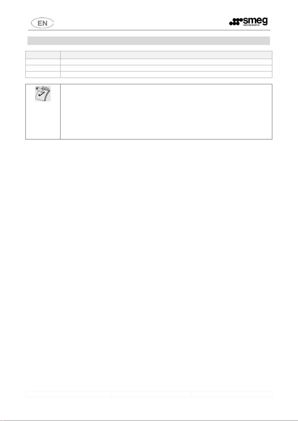
WD5090
WD5090
WASHER DISINFECTOR
- USER MANUAL -
Page 2

WD5090
USER MANUAL
2
CONTENTS
1 READ THE USER MANUAL WITH CARE ....................................................................................................................... 4
2 KEY TO THE SYMBOLS USED IN THE MANUAL AND ON THE APPLIANCE ................................................................... 5
3 INTENDED USE ........................................................................................................................................................... 6
3.1 DEFINTITION: “RESPONSIBLE AUTHORITY” IN RELATION TO THE DEVICE ........................................................ 7
3.2 STANDARD 15883 .............................................................................................................................................. 7
4 MODELS ..................................................................................................................................................................... 8
4.1 WD5090 models ................................................................................................................................................ 9
4.1.1 50Hz Models ................................................................................................................................................. 9
4.1.2 60Hz Models ............................................................................................................................................... 10
5 GENERAL WARNINGS ............................................................................................................................................... 11
5.1 ACCESSING AND REUSING THE DEVICE AFTER AN INCOMPLETE CYCLE ......................................................... 12
6 GENERAL OPERATING INSTRUCTIONS .................................................................................................................... 13
6.1 POWERING ...................................................................................................................................................... 13
6.2 CONTROLS ....................................................................................................................................................... 13
7 FUNCTIONING .......................................................................................................................................................... 14
7.1 HOW TO OPEN THE WASHING CHAMBER DOOR .......................................................................................... 14
7.1.1 MANUAL DOOR RELEASE PROCEDURE ....................................................................................................... 15
7.2 SIDE CABINET DOOR OPENING - only if present ............................................................................................. 15
7.3 HOW TO CONDUCT A WASHING/DISINFECTING CYCLE .................................................................................. 16
7.4 HALTING A PROGRAM IN PROGRESS ............................................................................................................. 17
7.5 PERFORMING A STAND-ALONE DRYING CYCLE ............................................................................................. 17
7.6 PRINTING OUT THE LAST CYCLE PERFORMED................................................................................................ 18
7.7 POSTPONING THE CYCLE START ..................................................................................................................... 18
7.8 SECURITY POLICY, USER AND SUPER USER PASSWORDS ................................................................................ 18
8 COMMISSIONING INSTRUCTIONS ............................................................................................................................ 20
8.1 USING THE WATER SOFTENER ........................................................................................................................ 20
8.2 USING DETERGENTS ........................................................................................................................................ 20
8.2.1 LIQUID DETERGENT INTAKE SYSTEM .......................................................................................................... 20
8.2.2 GENERAL PRECAUTIONS FOR DETERGENTS ................................................................................................ 21
8.3 HOW TO REGULATE THE WASHING PRESSURE IN THE SPRAYING ARMS ....................................................... 22
1 DETERGENTS ............................................................................................................................................................ 23
9 LOAD PREPARATION ................................................................................................................................................ 24
10 WASHING PROGRAMS - DESCRIPTION ..................................................................................................................... 25
10.1 WASHING AND DISINFECTING PROGRAMS FOR OPERATING THEATERS ........................................................ 25
10.2 A0 PARAMETER – THERMAL DISINFECTIONS .................................................................................................. 26
11 ABBREVIATIONS LEGEND ......................................................................................................................................... 27
Page 3

WD5090
USER MANUAL
3
12 ALARMS MESSAGES ................................................................................................................................................. 28
13 CLEANING AND MAINTENANCE ............................................................................................................................... 33
13.1 CLEANING THE DEVICE AND ITS PARTS ........................................................................................................... 33
13.2 DRYING AIR FILTER - only if present ................................................................................................................ 35
13.3 IF THE DEVICE IS TO BE OUT OF USE ............................................................................................................... 35
13.4 REUSING THE DEVICE AFTER A PERIOD OUT OF USE ...................................................................................... 35
13.5 TROUBLESHOOTING ........................................................................................................................................ 36
14 ROUTINE INSPECTIONS AND MAINTENANCE........................................................................................................... 37
14.1 DAILY ............................................................................................................................................................... 37
14.2 WEEKLY............................................................................................................................................................ 37
14.3 EVERY SIX MONTHS ......................................................................................................................................... 37
14.4 EVERY YEAR ..................................................................................................................................................... 37
15 INSTALLED MACHINE SET-UP ................................................................................................................................... 38
Page 4

WD5090
USER MANUAL
4
1 READ THE USER MANUAL WITH CARE
This manual is an integral part of the appliance.
Take good care of it and keep it to hand throughout the appliance’s life cycle.
This manual and all the information it contains must be read carefully before using the appliance.
Failure to read, misunderstanding or incorrect interpretation of the instructions provided in this manual may lead to
misuse of the appliance, put the operator at risk and considerably reduce the appliance’s performance.
Installation, maintenance and any repairs must be carried out by authorised technical staff.
Apart from leading to forfeiture of warranty cover, repairs performed by unauthorised staff may put the
user’s safety at risk.
Any components must always be replaced with genuine spare parts.
Use of the device in breach of the instructions provided by the manufacturer may jeopardise the specified
protection level (safety of the appliance) and the warranty cover for it (see point 5.4.4 of IEC 610101:2010).
The manufacturer declines all liability for uses other than those described in this manual.
Consumables (detergents, air filters, thermal printer paper, etc.) are not covered by the warranty, except
for any manufacturing defects.
The Warranty does not cover any parts found to be faulty due to negligent or careless use, improper use,
failure to comply with the appliance’s operating instructions, incorrect installation or maintenance,
maintenance or repairs performed using by unauthorised staff or repairs made with non-genuine parts,
damage during transport, or any circumstances in which the appliance’s defects cannot be traced back to
manufacturing faults. Any work relating to installation and connection to the intake and drain systems, and
the maintenance work described in the operator’s manuals, are also excluded from the Warranty.
Any accessories may not be installed on the appliance by the user; this must be done by authorised
technical staff.
To request technical documentation relating to accessories, contact the manufacturer.
The information in this manual is provided for guidance only. The contents and the equipment described may be
subject to change without notice.
Page 5

WD5090
USER MANUAL
5
2 KEY TO THE SYMBOLS USED IN THE MANUAL AND ON THE APPLIANCE
The following is the key to the symbols used on the appliance and in this manual, as required by point 5.4.4.e of
IEC61010-2-040:2015.
Read with particular attention.
(Symbol which appears beside particularly important instructions or warnings).
Warning, danger: refer to the manual.
(The symbol appears on the appliance’s technical dataplate to emphasise that staff must read the
manual before using the device.
The symbol appears in the manual next to safety instructions)
Warning, hot surface.
(the symbol is affixed to the appliance close to parts which may heat to high temperatures and
constitute a burn hazard - do not touch parts near this symbol. The symbol appears in the manual to
emphasise safety instructions relating to the burn hazard).
Warning, electric shock hazard.
(The symbol is affixed close to live parts - the device’s power supply must be disconnected before doing
any work on these parts. Never touch live parts unless the electricity supply is disconnected).
Transport and unpacking precautions.
Biohazard.
Flammability hazard.
At the end of its working life, the product must be consigned to a disposal plant for recovery and
recycling in accordance with the relevant legislation in the country of installation. Contact the specialist
disposal consortia.
At the end of its lifetime the appliance may be contaminated, especially the chamber and water circuit
(e.g. if the appliance has ended its working life due to a fault that has caused the failure of the last
thermal disinfection cycle): take appropriate care when decommissioning.
THIS APPLIANCE IS MARKED ACCORDING TO THE EUROPEAN DIRECTIVE ON WASTE ELECTRICAL AND
ELECTRONIC EQUIPMENT (WEEE). BY ENSURING THIS PRODUCT IS DISPOSED OF CORRECTLY, YOU WILL
HELP PREVENT POTENTIAL NEGATIVE CONSEQUENCES FOR THE
ENVIRONMENT AND HUMAN HEALTH, WHICH COULD OTHERWISE BE CAUSED BY INAPPROPRIATE
WASTE HANDLING OF THIS PRODUCT.
CE marking, notified body IMQ.
This symbol appears on the appliance’s technical data label and in this manual, indicating that it is a
medical device which holds EC CERTIFICATION issued by IMQ (“0015” is the code number of the notified
body IMQ).
Page 6

WD5090
USER MANUAL
6
3 INTENDED USE
Instrument washers for use in hospitals, class IIb medical devices (in accordance with the classification criteria
established by Directive 93/42 and subsequent additions and amendments, extended and amended by EC Directive
2007/47).
INTENDED USE: treatment, through washing and thermal disinfection, of instruments inside hospitals and dental
centers to prevent, thanks to thermal disinfection, the spread of infectious agents that could potentially harm dental
personnel and final patients.
This product is designed exclusively for the applications described in the manual, especially for CSSD (Central
Sterilisation Supply Departments), substerilisation, hospitals, clinics and laboratories. Any other use is considered
improper use.
The appliance is built to provide the following function:
Washing with Thermal Disinfection of surgical or dental instruments. Note: the treatment in an Instrument
Washer is no substitute for sterilisation. Disinfection in an instrument washer is intended to reduce the risks
for the staff who handle instruments and to prepare them for subsequent treatments and uses.
The appliance cannot be used to sterilize instruments or any other device.
The type of instrument which can be processed in a cycle depends on the washing trolley used.
The device is supplied as standard without washing trolleys; contact the manufacturer for advice about the trolleys
best suited to your needs.
Any use other than that described in this manual constitutes misuse.
The manufacturer declines all liability for uses other than those stated above.
The manufacturer declines all liability for any damage caused by the use of the appliance to wash
glassware or instruments not approved by their manufacturers for automatic decontamination by means of
thermal disinfection.
The appliance may only be used by specifically trained staff. The authorized installation engineer will
train the staff assigned to use the appliance at the time of installation.
The manufacturer declines all liability in the event of malfunctions or accidents caused by use of the
appliance by untrained staff.
The training of the staff responsible includes specific information on the possible risks involved in the use
of the appliance, and training in the safest possible way of carrying out the operating procedures.
The installation engineer is also responsible for notifying the responsible authority of the USER and
SUPERUSER passwords for access to the setup parameters. The responsible authority must keep these
passwords in a safe place.
It is the duty of the appliance’s RESPONSIBLE AUTHORITY to ensure that those using the equipment have
been suitably trained in its operation, its safe use and routine checks, and that this training is suitably
maintained.
Staff training should be checked regularly.
The installation engineer is responsible for ensuring that it operates correctly after commissioning.
Safety information supplied in compliance with 5.4.101.1 IEC61010-2-040:2015
Instrument manufacturers’ instructions should always be followed when choosing the most appropriate
disinfection treatment.
In particular, it is important to check the compatibility of the load for treatment with the specific washing
cycle chosen, in terms of the maximum temperatures reached and the chemicals used.
Information supplied in compliance with point 5.4.4.r IEC61010-2-040:2015.
Page 7

WD5090
USER MANUAL
7
3.1 DEFINTITION: “RESPONSIBLE AUTHORITY” IN RELATION TO THE DEVICE
Responsible authority/body: “individual or group responsible for the safe use and maintenance of equipment”.
Definition taken from point 3.5.12 of the IEC61010-1:2010 standard.
The responsible authority should be clearly identified within the facility where the appliance is used, (for example by
recording the relative names and responsibilities on corporate forms).
3.2 STANDARD 15883
The standard of reference for the performance of a thermal disinfection appliance is EN ISO 15883.
With reference to the point 6 of 15883-1: as well as the compliance of the device “as supplied”, in charge of the manufacturer, the
standard requires to undertake further checks relating to the device “as installed”, in a sequence of processes known as “validation”. The
validation process is in charge of the Responsible authority for the device.
VALIDATION
The validation process for a thermal disinfection device under EN ISO 15883-1 involves 3 different phases.
1. Installation Qualification - IQ
2. Operational Qualification - OQ
3. Performance Qualification - PQ
installation qualification - IQ
process of obtaining and documenting evidence that equipment has been provided and installed in accordance with its specification
operational qualification - OQ
process of obtaining and documenting evidence that installed equipment operates within predetermined limits when used in accordance
with its operational procedures
performance qualification - PQ
process of obtaining and documenting evidence that the equipment, as installed and operated in accordance with operational
procedures, consistently performs in accordance with predetermined criteria and thereby yields product meeting its specification
Note on performance qualification
Performance qualification must be carried out after completion of installation and operational qualification.
Performance qualification must be carried out whenever new or modified objects are placed in the appliance for washing and
disinfection, or new load systems are used, unless proof is provided that they are equivalent to an approved reference load or an object
or load system already approved in the past.
Performance qualification must be carried out when new process parameters (including process chemicals) are adopted.
Operational qualification should be repeated at set intervals to provide regular verification of the appliance’s operation.
Repetition of performance qualification for each appliance every year is suggested.
WARNING - USE OF PROBES FOR VALIDATION
The basic appliance does not feature a physical port as envisaged by the EN ISO 15883 standard for the insertion of probes with cable:
the use of wireless probes (dataloggers or similar) is recommended.
Page 8
WD5090
USER MANUAL
8
4 MODELS
SYMBOL
MEANING
feature present
optional accessory, installable on the model in question
-
feature not present and not installable on the model in question.
Notes on variants - Power supply:
Unless otherwise specified, the device is set for a power supply of three-phase plus neutral (3N~) –
this can be changed to single-phase on the user's premises by authorised technical staff. This
configuration is also referred to as "standard" (STD).
If a specific power supply is indicated (e.g. "230V three phase without neutral", or "230V singlephase"), this means that the variant is preset for a specific type of power supply, which cannot be
modified on the user's premises.
Page 9
WD5090
USER MANUAL
9
4.1 WD5090 models
WD5090: instrument washers, 90cm, equipped with forced air drying system and side cabinet to take detergent cans.
4.1.1 50Hz Models
Id. code
860242
860243
860248
860564
Model
WD5090T
WD5090TFO
WD5090TR
WD5090TRFO
P1 - Peristaltic detergent pump
P2 - Neutralising agent peristaltic
pump
P3 - Optional peristaltic pump
P4 - Optional peristaltic pump
P5 - Optional peristaltic pump
Drying system
HEPA H13 absolute filter (air)
Steam condenser
P1 Detergent dispensing
monitoring
P2 Neutralising agent dispensing
monitoring
P3 pump dispensing monitoring
P4 pump dispensing monitoring
P5 pump dispensing monitoring
Jerry can level monitoring P1 –
SP1
Jerry can level monitoring P2 –
SP2
Jerry can level monitoring P3 –
SP3
Jerry can level monitoring P4 –
SP4
Jerry can level monitoring P5 –
SP5
Rails in chamber for upper trolley
-
-
Side cabinet to take detergent
cans
Panel printer
Mains frequency
50 Hz
50 Hz
50 Hz
50 Hz
Electrical connection
STD
STD
STD
STD
Page 10
WD5090
USER MANUAL
10
4.1.2 60Hz Models
Id. code
860249
860250
860261
860469
860611
Model
WD5090T6
WD5090TF6
WD5090TR6
WD5090T36
WD5090TR36
P1 - Peristaltic detergent pump
P2 - Neutralising agent peristaltic
pump
P3 - Optional peristaltic pump
P4 - Optional peristaltic pump
P5 - Optional peristaltic pump
Drying system
HEPA H13 absolute filter (air)
Steam condenser
P1 Detergent dispensing
monitoring
P2 Neutralising agent dispensing
monitoring
P3 pump dispensing monitoring
P4 pump dispensing monitoring
P5 pump dispensing monitoring
Jerry can level monitoring P1 –
SP1
Jerry can level monitoring P2 –
SP2
Jerry can level monitoring P3 –
SP3
Jerry can level monitoring P4 –
SP4
Jerry can level monitoring P5 –
SP5
Rails in chamber for upper trolley
-
- -
Side cabinet to take detergent
cans
Panel printer
Mains frequency
60 Hz
60 Hz
60 Hz
60 Hz
60 Hz
Electrical connection
STD
STD
STD
230 3~
230 3~
Page 11
WD5090
USER MANUAL
11
5 GENERAL WARNINGS
.Leaning or sitting on the open door of the device might cause it to tip over, putting people in danger.
The door is not designed primarily to support loads.
.The maximum weight which can be loaded on the door, including the weight of the instrument trolley,
must never exceed 37kg (if the weight of the instrument trolley and baskets is excluded, the maximum
processable load must never exceed 23kg).
.For optimal DRYING, the load for processing must never exceed 15 kg.
.With use of the device, localised or general discolouring of the heating element may occur. This is normal
since it is due to the operating mode and does not reduce the appliance’s effectiveness.
.In the event of malfunction, disconnect the appliance from the electricity supply and turn off the water
tap. Then contact your nearest authorised Service Centre.
.Open the door carefully, first waiting for the wash cycle to end. The appliance has an automatic door
opening system; do not force the door open while a program is in progress.
.The appliance must only be used by staff suitably trained in its operation.
.The chamber of the appliance is not designed for users to climb into it. The user must never climb into the
chamber; this might put his safety at risk (ref. 7.102 IEC61010-2-040:2015).
DEMI WATER ABSENCE
If demineralised water is not available, the user is responsible for ensuring that the quality of the water
supplied to the medical device does not cause mineral salts or other substances to be deposited on the
treated instruments, rendering their subsequent use unsafe.
Do not place flammable substances inside the device. Do not use flammable detergents.
Never place alcohol or solvents such as turpentine, which might cause an explosion, inside the appliance.
Do not place materials dirty with ash, wax or paint inside the appliance.
Never touch the heating element immediately after the end of a wash programme.
Do not touch any residual liquids left inside the washing chamber; scalding hazard (ref. 7.102.c IEC610102-040:2015).
When moving the appliance around, a forklift truck or pallet truck must be used.
Before leaving the factory, the base of the appliance is secured to a pallet, which is used for lifting and
transporting it.
Do not use appliances which have been damaged in transit!
If in doubt, contact your dealer.
Once decommissioned, the appliance must be rendered unusable. Cut the power supply cable after
removing the plug / disconnecting the cable from the power socket.
Page 12

WD5090
USER MANUAL
12
5.1 ACCESSING AND REUSING THE DEVICE AFTER AN INCOMPLETE CYCLE
The instructions relating to the device’s safety in the event of an incomplete operating cycle are provided in
compliance with points 5.4.4.g and 13.1.102 of IEC61010-2-040:2015.
WARNING
If a disinfection cycle is interrupted (by the user or due to an alarm generated by the appliance itself): take
care when handling the instruments and the load in general in the washing chamber. The load and the
internal parts of the appliance might be biologically contaminated/infected.
Before handling tools or performing any maintenance: Perform a complete disinfection cycle or, if you
cannot perform a complete Thermo-disinfection cycle, handle tools with caution (using protection devices
required for the handling of infected instruments, eg. gloves, lab coat).
DANGER, HOT SURFACES
The appliance performs a thermal disinfection cycle using water at high temperatures (up to 93°C) and
detergents. If, in the event of a failure, there is water in the chamber when the door is open: avoid contact
with the skin, burning hazard and risk of irritation due to the toxicity of the chemicals used.
Never touch the heating elements inside the chamber.
Contact Smeg authorised technical staff in the event of a failure.
Fig. 1- View of inside of chamber, detail of heating elements.
Do not touch
the heating
elements
Page 13

WD5090
USER MANUAL
13
6 GENERAL OPERATING INSTRUCTIONS
6.1 POWERING
The main switch “S1”, that powers on the device, is located in the cabinet at the side and can only be accessed after
the door of the side compartment has been opened. The door of the side cabinet can be open simply pulling its
handle.
6.2 CONTROLS
The keyboard is divided into two separate sections:
. The left-hand part of the display with keys for starting and stopping a program, and for the reset process;
. The right-hand part of the display, which contains the keys used for selecting/editing programs, selecting the
machine parameters and the various functions/adjustments.
Page 14

WD5090
USER MANUAL
14
A complete list of the keys and their relative functions is given below.
KEY
FUNCTION
KEY
FUNCTION
1 - START, starts the selected program
6 - LEFT – DRYER ON, key used to select the
separate drying cycle (if available); it is also
used for moving to the left in each menu.
2 - RESET, forces the machine to run through a
reset procedure (both in the case of a deadlock
and in other situations, such as those after an
alarm has occurred)
7 - RIGHT – DRYER OFF, selection key for
deactivating the drying cycle (if available); it is
also used for moving to the right in each menu.
3 - STOP, stops the current program (also for
the printing of the last cycle).
8 - ENTER, confirms the selection made /
program selection / door opening.
4 - UP, selection key (scroll up).
9 - INC, increases the value / selects “yes”/
setting of the delayed start (max 24h)
5 - DOWN, selection key (scroll down),
(also for the printing of the machine
parameters).
10 - ESC, quits the current mask and goes back
to the previous step.
11 - DEC, decreases the value in question /
selects “no”
Symbols similar to the keys appear on the bottom line of the display as their functions are activated.
Some keys have special functions depending on the active screen, such as the "STOP" key: if used when the machine is
stopped, has the function to “send to the printer” the last cycle performed.
In case of “no energy supply”: the door is locked.
Do not try to force the opening, in order to avoid damages to the security lock.
7 FUNCTIONING
Basic steps for using the device, once installed, are:
1. Correct positioning of the load to be processed within the washing trolleys in the chamber.
2. Installation and connection of detergents tanks in the cabinet side.
In the following, the instructions to access the washing chamber of the device and for the opening of the cabinet side.
7.1 HOW TO OPEN THE WASHING CHAMBER DOOR
The device is provided with an automatic locking system.
Do not force the opening of the door, proceed as described:
Connect the machine to the electricity supply.
Open the hatch of the side cabinet and power on the machine turning the main switch on.
Wait for the device initialization, then press the “ENTER” key for the opening of the door.
The door may be opened during the cycle only if the temperature inside the washing chamber has not
exceeded 40°C. Use the keyboard to open the door.
Depending on the settings chosen for the system, a password must be entered to open the door.
It is always advisable to wait until the cycle terminates before opening the door.
To open the door without connecting the appliance to the electricity supply (useful for emergencies or in case of
power blackouts), the manual release system has to be used (see next point).
Page 15

WD5090
USER MANUAL
15
Per aprire la porta senza collegare elettricamente la macchina, utile in casi di emergenza o di mancanza tensione,
occorre utilizzare il sistema di sblocco manuale (si veda il paragrafo successivo).
7.1.1 MANUAL DOOR RELEASE PROCEDURE
If necessary, due to a malfunction or power blackout, the appliance can be opened manually by releasing the lock
using a screwdriver with stem Ø3mm; taking care not to damage the device.
1. This procedure is only possible with the appliance in “stand by” status, with no cycle running.
2. Warning: before opening the appliance manually, disconnect it from the electricity supply.
3. Insert a screwdriver or a rod 3 mm in diameter into the hole in the bottom of the centre of the front panel.
4. Push the pin upward until the lock is released
fig. 2 – Diagram showing how to release the lock by hand in any emergency.
It is dangerous to open the door when the temperature inside the washing chamber exceeds 50°C!
The manufacturer declines all liability for damage to persons or property caused by forcing the door open
during a thermal disinfection cycle.
7.2 SIDE CABINET DOOR OPENING - only if present
The steel door of the side compartment is closed by a “magnetic lock”: pull the handle of the door to open it. This will
give access to the switch that powers the machine and the compartment where the detergent tanks are positioned.
fig. 3 – Side cabinet door opening.
Page 16

WD5090
USER MANUAL
16
7.3 HOW TO CONDUCT A WASHING/DISINFECTING CYCLE
Once the device has been installed, the detergent cans have been connected and the trolleys have been loaded, to
perform a washing cycle:
Power up the device by turning the MASTER SWITCH from “0” to “I” (for devices with side cabinet, the switch is
accessed by opening the cabinet door);
Wait for a moment to allow the system to load: the screen of the last program selected will appear (e.g.
“PLASTIC 70°C”);
Press ESC to access the program selection menu;
Use the UP and DOWN keys to choose the program required.
Press ENTER to confirm the program.
Press START to start the selected program.
< 1 PREWASH >
< 2 DEMI PREWASH >
< 3 PLASTIC 70°C >
< 4 SHORT 60°C >
. . .
Fig. 4 - Program selection screen
PR: PLASTIC 70°C + Dry
(000003)
Phases N.: 5
Duration: 1:10:00
< Drying On >
05/02/2013 08:30:15
Fig. 5 - Screen of the program selected
Once the program has started, the display shows the following information:
the name of the program being run (e.g. “PLAST 70°C”);
the current phase and the process being carried out (e.g. “PRELOADING”);
TL - the temperature inside the washing chamber;
TC - the control temperature;
RunT - the time since the program started.
The end of the cycle is shown on the display by a specific screen: the cycle has been completed successfully. At the end of the cycle
the user can open the door by pressing ENTER.
Once the door is open, the processed instruments can be unloaded. The device is ready to perform a new washing/disinfection
program.
It is best to wait a few minutes between cycles, with the door of the device open, to allow the washing chamber to
cool, making the next washing cycle more effective.
A low temperature at the start of the washing cycle provides full benefits from the combined action of time and
temperature during the process and the detergent used.
PR: PLASTIC 70°C + Dry
F0 PREWASH
PRELOADING
TL 19.5 TC 19.8
RunT 0:00:20
Fig. 6 - screen of the programming which is running
PR: PLASTIC 70°C + Dry
PROGRAM ENDED
OPEN THE DOOR?
Fig. 7 - “Program ended” screen.
Page 17

WD5090
USER MANUAL
17
7.4 HALTING A PROGRAM IN PROGRESS
To interrupt a program in progress: press STOP.
Once the button is pressed, the program switches to pause state:
The door can only be opened until the temperature is less than 40°C, by pressing ENTER
Restart the cycle within 60 seconds by pressing START.
7.5 PERFORMING A STAND-ALONE DRYING CYCLE
The drying phase is set for every program (except for prewash programs) by default.
To start a “stand-alone” drying phase:
Press “LEFT” from the menu of the selected program.
The drying phase activation screen appears: press ENTER to confirm the start of drying (or press ESC if you prefer to go
back to the previous screen).
Parameters on the display during drying:
o Phase name
o TA1: Drying System temperature probe;
o TT: phase target temperature;
o RunT: time passed.
DRYING
Confirm?
Fig. 8 - drying cycle selection screen: Confirm with ENTER.
PR: DRYING
DRYING
TA1 74.5
TT 80.0 RunT 0:00:55
Fig. 9 - screen: drying cycle in progress.
At the end of the phase, open the door and wait a few minutes before extracting the instruments, to allow both the well and the
processed material to cool down (the drying phase concludes with a cooling phase).
Page 18

WD5090
USER MANUAL
18
7.6 PRINTING OUT THE LAST CYCLE PERFORMED
N.B.: the printer is an optional and not part of the standard equipment.
The last cycle performed can be printed out with the device in standby mode. Proceed as follows:
Press STOP with the screen of the last cycle performed on the display.
The print confirmation prompt screen appears: press ENTER to confirm or ESC to abort.
PR: PLASTIC 70°C + Dry
(000003)
Phases N.: 5
Duration: 1:10:00
<Drying On>
05/02/2013 08:30:15
Fig. 10 - screen of the last program performed
PRINT LAST CYCLE?
< YES >
Fig. 11 - printout confirmation screen.
7.7 POSTPONING THE CYCLE START
Maximum delay setting: 10 hours. To postpone the start of a cycle:
press INC with the screen of the cycle selected on the display.
The delay time setting screen appears;
Set the delay time using the R and L selector buttons to locate the cursor on the hours and minutes and the INC and DEC
buttons to increase or decrease the value.
PR: 3 PLASTIC 70°C + As
(000003)
Phases N.: 5
Duration: 1:10:00
<Drying On>
05/02/2013 08:30:15
Fig. 12 - screen of the last program performed
PR: postponed
3 PLASTIC 70°C
Type delay
Hours 00 Min 00
05/02/2013 08:30:15
Fig. 13 - postponed start setting screen.
7.8 SECURITY POLICY, USER AND SUPER USER PASSWORDS
For safety reasons, the device implements a protection policy with four password levels that enable or deny access to
the menus of the appliance.
user level: concerns the people who actually operate the machine (nurses, assistants, department heads). This
password enables access to the “program selection” and “change password” menus only.
super user level: concerns the person in charge of the machine (department head, clinical engineer, etc.). This
password can be used to access the following menus:
o PROGRAMMING: Loading Programs;
Page 19

WD5090
USER MANUAL
19
PROGRAM EDITING -> only in relation to the amount of detergent and the drying parameters;
COPY
NEW PROGRAM
o UTILITY: accesses all the sub-menus (can also change the user passwords)
o WASHING PARAMETERS: only certain sub-menus, as listed below:
WATER CONNECTION
WATER TRAP WASH
REGENERATION
DRAINING
Technical level: concerns authorized technicians.
All the menus in the lower levels as well as other “WASHING PARAMETERS” submenus can be accessed from this level,
i.e.:
EXTRA FILLING TIME
DRAINED WATER RECOVERY
CONDENSER ACTIVATION
DETERGENT DISPENSERS
FLOWMETER
CONDUCTIVITY SENSOR
DWP ACTIVATION
TEMPERATURE ADJUSTMENT
MAINTENANCE
Manufacturer level: concerns the manufacturer of the appliance.
Default Passwords:
USER
PASSWORD
USER
PASSWORD
User 1
1
User 11
B
User 2
2
User 12
C
User 3
3
User 13
D
User 4
4
User 14
E
User 5
5
User 15
F
User 6
6
User 16
G
User 7
7
User 17
H
User 8
8
User 18
I
User 9
9
User 19
J
User 10
A
User 20
K
SuperUser (Tech
user)
The password will be given
by authorized technician
Remember to change the password when the appliance is used for the first time so as to be certain of who
is enabled to access the machine.
The “User Control Activation” option can be activated to make sure that the appliance is operated by
authorized users.
Page 20

WD5090
USER MANUAL
20
8 COMMISSIONING INSTRUCTIONS
Once the appliance has been installed correctly, it must be prepared for use:
Fill up with regenerating salt.
Prepare the detergent and any other chemicals.
8.1 USING THE WATER SOFTENER
The appliance is equipped with a water softener which removes the substances that cause hardness from the inlet
water.
fig. 14 – The salt tank is accessible with the door open; filling the softener tank with regenerating salt.
The softener tank contains about 1 kg of coarse salt. The salt tank is in the bottom of the inside of the well. Remove the bottom
basket, unscrew the cap of the tank by turning it anticlockwise and pour in the salt using the funnel supplied; take care not to spill
salt in the tank. Remove any salt residues before screwing the cap back on.
ATTENTION
The first time the device is used, a litre of water must be poured into the tank with the salt. Whenever the tank is filled,
always take care to ensure that the cap is firmly closed. The mixture of water and detergent must not get into the salt
tank, as this would impair operation of the regeneration resins.
Only use coarse salt for domestic dishwashers. Do not use cooking salt.
Fill up with salt when necessary before starting a washing program, so that any excess salt solution will immediately be
removed; if salt water is left to stand inside the tank, it may cause corrosion. Carry out a prewash cycle to prevent this if
necessary.
8.2 USING DETERGENTS
One fundamental factor for a good washing process is the type of detergents used.
The manufacturer guarantees excellent washing results with the use of the recommended products.
The device is equipped with automatic detergent dispensing devices.
DISPENSING
DEVICE
USE OF DEVICE AS HOSPITAL INSTRUMENTS
WASHER
USE OF DEVICE AS GLASSWARE WASHER
P1
neutral or weak alkaline liquid detergent
neutral or weak alkaline liquid detergent
P2
acid neutralising agent
acid neutralising agent
P3
additional disinfectant detergent
NaOH 33%
P4
lubricant
antifoam
P5
additional detergent
additional detergent
ATTENTION
If the can level sensors are not fitted: check the levels of product in the cans / bottles to ensure that programs are not
performed without detergent or neutralising agent.
Always comply with the INSTRUCTIONS provided by detergent PRODUCERS, especially with regard to the
RECOMMENDED DOSES, the correct TEMPERATURES for their use and STORAGE instructions. Safety information about
doses supplied in compliance with 5.4.4.s of IEC61010-2-040. Refer to the product instructions and technical safety data
sheets.
8.2.1 LIQUID DETERGENT INTAKE SYSTEM
Standard Configuration, with LEVEL SENSOR. Intake nozzle with integral:
Level sensor and support for fitting onto the can.
High-strength rubber hose for connection between intake pipe and peristaltic pump.
Detergent intake filter, fitted directly on the suction nozzle pipe.
Page 21

WD5090
USER MANUAL
21
WARNING
The label on the intake pipe must correspond to the type of detergent being used. Refer to the following
colour code:
P1 - White/clear: alkaline detergent; P2 - Red: acid neutralising agent
P3 - Blue: additive; P4 - Green.
Connection errors reduce the effectiveness of the process and may damage parts of the circuit. Detergent
intake system connection errors lead to the loss of Warranty cover for the parts concerned.
The intake pipe is supplied complete with intake filter. Make sure that the filter is always fitted and correctly
positioned to keep the detergent dispensing system in good working order. Check the rubber connection
hose regularly for leaks.
fig.15 - Fitting the detergent intake nozzle into the can. Fit the cap over the top of the can for a perfect, secure connection. The
intake nozzle is supplied complete with intake filter. (the illustrations show various versions available).
8.2.2 GENERAL PRECAUTIONS FOR DETERGENTS
HANDLE DETERGENT CANS WITH CARE
Detergents may be TOXIC. Refer to the product safety data sheets.
Once a product has run out, replace the empty can with a full can of the same product.
If the product left in the old can is poured into the new one, take care not to overfill the new cans to ensure
that they will not overflow when the suction nozzles are inserted. Gloves must be worn during any handling
of detergents. Information supplied in compliance with 5.4.3.o, 5.4.4.n, 5.4.4.q IEC61010-2-040:2015
DETERGENT SAFETY DATA SHEETS.
Detergent SAFETY DATA SHEETS must be kept: close to the place where detergents are stored, close to the
appliance, in an easily accessible location. The latest versions of the safety data sheets should be requested
regularly (e.g. once a year). Safety data sheets will be supplied by the producer on request. Refer to safety
data sheets for first aid procedures in the event of accidental contact with detergents.
DISPOSAL
Information supplied in compliance with point 5.4.4.L of IEC61010-2-040:2015.
DISPOSAL of any product residues and containers (cans and bottles): refer to the “DISPOSAL ADVICE” section
of product safety data sheets. The appliance’s responsible authority must dispose of detergent residues and
containers in accordance with the relevant national or local legislation.
Page 22

WD5090
USER MANUAL
22
8.3 HOW TO REGULATE THE WASHING PRESSURE IN THE SPRAYING ARMS
The pressure of the washing water in the top and bottom spraying arms can be regulated by means of the adjuster
under the spraying arm itself.
Turn the adjuster lever fully towards the left (normal position) to obtain the maximum pressure in the top
spraying arm or in the injection system.
Turn the lever towards the right (towards the bottom of the tub) to obtain the maximum pressure in the
bottom spraying arm as the top one will be throttled.
fig. 16 - Pressure regulator. Position 1: Maximum flow at top level.Position 2: Balanced flow.
Position 3: Maximum flow from bottom arm.
Page 23

WD5090
USER MANUAL
23
1 DETERGENTS
One of the fundamental factors in achieving a good washing process is the type of detergents used.
The manufacturer guarantees excellent washing results with the use of the products recommended.
Contact your local dealer for advice about the types of detergents suitable for your application, and their modes of
use.
ATTENTION
Always comply with the INSTRUCTIONS provided by detergent PRODUCERS, especially with regard to
the RECOMMENDED DOSES and the correct TEMPERATURES for their use.
Safety information about doses supplied in compliance with 5.4.4.s of IEC61010-2-040.
Refer to the product instructions and technical safety data sheets.
Technical data sheets are available on request.
WD
The effectiveness of the washing action and consequent thermal disinfection provided by this appliance
has been tested in compliance with EN 15883-1 and 15883-2 using the cleaning agents listed in this
manual.
The parameters of the various phases of the programmed washing cycles (duration, temperature,
extension and doses) have been calculated on the basis of the use of these agents.
The appliance's effectiveness and correct operation cannot be guaranteed in the event of use of
cleaning agents other than those recommended here.
N.B.: the P3, P4, P5 pumps are optional accessories.
Recommended detergents for WD
Alkaline detergents (pump P1)
DETERLIQUID C2
Acid neutralising agents (pump P2)
ACIDGLASS C2
Disinfectant (pump P3)
Contact the manufacturer.
Lubricant / drying additive
Contact the manufacturer.
Weakly alkaline enzymatic detergents (detergent that can be used in combination with the P1 pump, based on
process requirements)
DENTALZYM
WARNING
WD: Do not use powder detergents: this may damage instruments’ internal mechanisms and
corrode titanium surfaces.
Do not add detergent to the acid neutralising agent jerry can: this will reduce the effectiveness of
the wash.
Use products recommendend by the manufacturer
Page 24

WD5090
USER MANUAL
24
9 LOAD PREPARATION
Effective disinfection starts in the instrument preparation phase. To make sure this occurs, eliminate any possible
coarse residue remaining from previous activities using suitable soaking methods and treatments before placing the
instruments in the appropriate baskets “delicately.”
Instruments made in stainless steel cannot be immersed in physiological solutions of sodium chloride for any reason,
as extended contact with this solution provokes corrosion creating holes and damage to the surface due to stress
corrosion.
Avoid overloading the instrument basket holders. Slag, skin disinfectant residue, physiological solutions, etc. must
not enter the treatment containers. The containers must always remain closed to avoid additional drying. It is
advisable to perform dry treatments when possible.
The instruments are immersed in a combined solution of disinfectant and detergent with no fixed protein effects, as a
preference when treating liquids. However, disinfectants based on aldehydes have a fixing effect. Therefore, we
strongly suggest precisely following the indications provided by the manufacturer regarding concentrations and action
times, as well as the possible addition of detergent additives.
Always avoid long time intervals between this preliminary treatment and the instrument washer treatment as the
risk of corrosion exists for both methods.
The instruments must be placed appropriately in instrument holders suitable for machine washing. To assure effective
cleaning, the articulated instruments (scissors, clamps and forceps) must be opened to avoid overlapping their
surfaces as much as possible. The instrument holders, such as baskets, racks and fixing devices, must be designed to
prevent shadow areas in the following cleaning and disinfecting phase.
Instruments that can be disassembled must be put away according to the instructions provided by the manufacturer.
Instruments used for micro-surgery must be placed on special racks or appropriate fixing devices.
Residue present on orthodontic instruments, such as material used for lead sealing or acid substances used for
removing cement, must be eliminated immediately after use to prevent the risk of hardening and/or corrosion.
Components of motor operated surgery systems must be disassembled immediately after use according to the
instructions provided by the manufacturer.
Simple tools, such as drills or saw blades can be treated like surgical instruments only if they are reusable medicalclinical products.
Avoid direct and repeated contact with dirty instruments as much as possible.
Always use extreme caution. Use all the individual protective devices available for this type of operation,
before and after treatment.
Page 25

WD5090
USER MANUAL
25
10 WASHING PROGRAMS - DESCRIPTION
The default ‘original’ programs are installed in program positions 1 to 20. These programs have been researched and
formulated so as to guarantee the best possible washing and disinfecting results. However, they can be changed in
relation to the quantity of detergent.
The remaining 10 positions from 21 to 30 are empty and can be used by the customer to create his own programs.
These new programs can either be created in the manual mode by means of the keyboard, or by using the
“WDTRACE” software (which can be purchased as an optional).
It is always possible to reinstall the original programs by loading them (consult the relative section).
10.1 WASHING AND DISINFECTING PROGRAMS FOR OPERATING THEATERS
The annex “Program Table” document describes the functions accomplished by the Operating Theater default
programs.
Only the default peristaltic pumps are activated in the standard programs. To activate the other pumps, access the
programming menu and activate them in the required phase.
A drying phase for the material can be added to the washing program.
To prevent possible contamination amongst the various cycles due to water residues that may have remained after a
program, it is advisable to run program N° 1 (chamber prewash), empty chamber, at the beginning of a work day as
a preventive safety measure.
A washing program generally comprises phases of different types:
Prewash with mains or demineralized water
dilutes or softens the pollutants on the instruments; Use cold water without additives to eliminate coarse dirt and
foam substances.
Hot alkaline wash
effective action that detaches the pollutants from the walls and solubilizes them; this phase is usually performed at
temperatures between 40°C and 65°C for a few minutes. Alkaline or neutral detergents are used.
Neutralizing in an acid environment
action that eliminates alkaline residues
solubilization of the calcium carbonate precipitates from the surfaces of the instruments
prevents the surfaces from becoming opaque
Rinsing with mains water
dilution of the previously used chemical additives
every rinse dilutes the initial concentration of the pollutant by about 99%
Rinsing in demineralized water
dilutes the inorganic salts and any organic fractions in the mains water
Thermal disinfection
Thermal disinfection is a hot washing phase where the washing temperature exceeds 70°C and is maintained for a
period of time that depends on the required thermal disinfection action.
Consult the next section for details about the thermal disinfection process.
Drying phase
Final process phase that must guarantee sufficient drying
Page 26

WD5090
USER MANUAL
26
10.2 A0 PARAMETER – THERMAL DISINFECTIONS
The A0 parameter (introduced by the EN ISO 15883 standard1) allows a numerical value to be assigned to the thermal
disinfection carried out.
When calculating the parameter, only the time intervals during which the temperature is above 65°C are considered.
For our thermal disinfection programs, the calculation is simplified by only including the “extension” phase, when the
temperature is kept constant at close to the target value set.
Programs that include thermal disinfection have therefore been designed to offer the following A0 values:
Temperature [°C] and time [min]
A0
90°C - 1’
600
90°C - 5’
3000
93°C - 5’
6000
93°C - 10’
12000
The formula for calculating A0 is given below.
10
80
0
10
T
A
= Time in seconds for which the disinfection temperature must be maintained.
T
= Disinfection temperature in °C.
If the temperature is 80°C, A0 is equal to the temperature maintenance time in seconds.
1
EUROPEAN STANDARD EN 15883 “Washer-Disinfectors” , with particular reference to section 3 Terms and Definitions
and annex B, A0 concept. of part 1 of the standard, 15883-1.
Page 27

WD5090
USER MANUAL
27
11 ABBREVIATIONS LEGEND
Abbreviations used to identify the components
BPE: Door-lock system
EVCC: steam condenser inlet valve
EVD: Demineralized water inlet valve.
EVF: Cold water inlet valve.
EVR: Water softener regeneration valve.
FM1, FM2… , FM5: peristaltic pumps P1, P2… P5 flowmeters
FMC: warm water flowmeter
FMD: demineralized water flowmeter
FMF: Cold water flowmeter
K: heating elements relay
MA: drying system motor.
MCM: Door position (signal switch)
MCP: Door position (signal switch)
ML: washing pump
MS: draining pump
P1, P2, …, P5: detergents peristaltic pumps
PAP: high pressure switch (washing pump ML monitoring)
PL1: working level pressure switch
PS: safety level pressure switch.
PSC: steam condenser draining pump.
R1, R2, R3: chamber heating elements.
RA: Resistenza asciugatore Drying System
EMF (SF): Mains EMI filter (electrical).
SP1, SP2, … , SP5 (also SL1, SL2,… SL5): Detergent tanks level sensors.
SLC: Steam condenser level sensor.
SS: Salt sensor (for the salt presence in the softener reservoir)
TA1: PT1000 probe, Drying temperature sensor
TCL: PT1000 probe, washing chamber temperature control sensor
TL1: PT1000 probe, washing chamber temperature working sensor
THS1: Drying system elements safety thermostat.
THS: Chamber heating elements safety thermostat.
Page 28

WD5090
USER MANUAL
28
12 ALARMS MESSAGES
There are two different situations, depending on how serious the fault is:
warning messages; there will be a message allowing the user to ignore the warning and proceed with the
selected cycle.
true alarm signals. The user must press the “RESET” button and comply with the relative procedure in order
to overcome the situation.
By and large, an alarm indicates that the machine is operating in a faulty way and needs to be repaired by a
technician. Sometimes, however, the alarm may be caused by a temporary situation. Before calling the authorized
Technical Assistance service, you are therefore advised to make a RESET and repeat the cycle a second time. Call the
authorized Technician if the alarm persists.
When an alarm message is noticed: Refer to the table below to find out what the code means and the relevant
countermeasures. Apply the countermeasures recommended for the specific circumstances.
DEFAULT PROCEDURE for all the alarms:
1. Perform the RESET cycle.
2. If the alarm message disappears after the RESET cycle: normal use of the device can be
restarted.
3. If the alarm message persists after the RESET cycle: switch the device off and back on using the
“On/Off” main switch (Wait at least 10 seconds after switching off before switching back on
again).
4. If the alarm occurs when the device is restarted: retry the RESET.
If a cycle has been stopped during a high temperature phase, remember that the temperature must drop
below 45°C before the door can be opened.
If the alarm persists even after the RESET procedure:
1. Turn off the water supply taps.
2. Disconnect the appliance from the electricity supply.
3. Check that all the device’s connections (electricity and water) are correct and there have been no changes
from the initial installation conditions.
4. Contact the After-Sales Service.
In case of water leakage: immediately Turn off the water supply taps and contact the After-Sales service.
Maintenance and any repairs must be carried out by authorized technical staff.
For your own safety and for the safety of the device, the user activities are limited to control activities,
external to the device, and to the activation of the RESET cycle, if requested.
ALARM ID
DISPLAY MESSAGE
MEANING AND SUGGESTED USER ACTION
ID1
“Water heating failed”
Water not heated within time allowed.
.Check the condition of the safety thermostat.
.follow the DEFAULT PROCEDURE described above.
ID2
“Temp. Probe TL1-TC”
The temperature difference between the two probes, “TL1” and
“TC”, is more than 2°C
.follow the DEFAULT PROCEDURE described above.
ID4
“Overtemperature TL1”
Probe “TL1” (chamber temperature) reads a higher temperature
than the target one.
.follow the DEFAULT PROCEDURE described above.
Page 29

WD5090
USER MANUAL
29
ALARM ID
DISPLAY MESSAGE
MEANING AND SUGGESTED USER ACTION
ID5
“Probe TL1 disconnected”
Working temperature probe “TL1” is generating an abnormal
signal (probe “open”).
.follow the DEFAULT PROCEDURE described above.
ID7
“Probe TA1 disconnected”
Drying temperature probe TA1 is generating an abnormal signal
(probe “open”).
.follow the DEFAULT PROCEDURE described above.
ID10
“Probe TCL disconnected”
Control temperature probe TLC is generating an abnormal signal
(probe “open”).
.follow the DEFAULT PROCEDURE described above.
ID11
“Lack of cold water”
No cold water during filling phases.
.Check the water supply.
.Check that the intake tap is open.
.Check the water supply pressure.
.Check that the filler hoses are correctly positioned.
ID12
“Lack of warm water”
The same as ID11 for the warm water.
.Check the correct setting of the parameters of the device
(effective presence/absence of warm water).
ID13
“Lack of demi water”
The same as ID11 for the demi water.
.Check the correct setting of the parameters of the device
(effective presence/absence of demi water).
ID17
“Cold water load time exceeded”
Cold water filling time not correct.
.The same checks as for ID11
ID18
“Warm water load time
exceeded”
Warm water filling time not correct.
.The same checks as for ID12
ID19
“Demi water load time exceeded”
Demineralized water filling time not correct.
.The same checks as for ID13
ID20
“Water load system failure”
.The same checks as for ID11, 12, 13
ID22
“Cold water flowmeter failure”
.The same checks as for ID11
ID23
“Insufficient water in chamber”
Chamber water level too low.
.The same checks as for ID11, 12, 13
. Verify that there are no leaks from the machine, highlighted by
the presence of water near the device.
ID24
“NO water in chamber”
.The same checks as for ID23.
ID25
“No Press in Hyd Sys Foam(?)”
Anomaly related to the circulating pump “ML”. Circulating pump
pressure too low. There may be foam in the chamber.
.Check the type of detergent used.
Page 30

WD5090
USER MANUAL
30
ALARM ID
DISPLAY MESSAGE
MEANING AND SUGGESTED USER ACTION
ID29
“Washing chamber drainage
failed”
Chamber does not empty. No drainage.
.Check the connection to the water drain,
especially that the height of the drain connections complies with
the specified requirements and that there are no restrictions in
the drain hoses.
ID30
“Safety chamber level exceeded”
During the working cycle, the chamber water level exceeds the
safety level.
Check the water supply to the appliance:
1. Intake pressure.
2. That the connections are correctly set, as specified.
ID31
“Safety level
Safety level failed”
.The same checks as for ID30
ID32
“Sump full
Turn the taps off”
Water standing in washing chamber with appliance in standby.
.The same checks as for ID30
ID33
“Lack of water
in the Condenser”
Steam condenser water intake anomaly.
Check the water supply:
1. Intake water pressure
2. That the connections are correct, as specified in this manual.
3. Blockages or restrictions in hoses.
4. Check intake water hardness (hard water contribute to steam
condenser nozzles obstruction).
ID34
“Condenser Drainage
failed”
Steam condenser water drainage failure.
Check that the drain connections are correct:
1. Height and position of the drain connection
2. That the connections are correct, as specified in this manual.
3. Blockages or restrictions in hoses.
ID37
“Not reached Target
Cooled Drainage”
Drainage problems when using a mixture of water. The use of a
mixture of water is an option adopted in special cases to cool the
water discharged into the drain.
Check:
1. The intake water temperature; if the water is not cold enough
(recommended T<25°C) there may be difficult in achieving the
target temperature.
2. Problems with drain; check that the hoses and drain
connections meet the specified requirements.
ID38
“Cooled Drainage
failed”
.The same checks as for ID37
ID41
“Detergent 1
Inflow failed”
. Check the detergent presence.
. Check that the detergent intake nozzle is correctly positioned in
the tank.
. Check for detergent leaks (pools of detergent around the
device).
ID42,
ID43,
ID44, ID45
“Detergent 2, 3, 4, or 5
Inflow failed”
.The same checks as ID41, for the detergents 2, 3, 4, 5.
ID46
“Pump tube 1
clogged”
.The same checks as for ID41
Page 31

WD5090
USER MANUAL
31
ALARM ID
DISPLAY MESSAGE
MEANING AND SUGGESTED USER ACTION
ID47,
ID48,
ID49, ID50
“Pump 2, 3, 4 or 5 tube
clogged”
.The same checks as ID41, for the detergents 2, 3, 4, 5.
ID52
“Door 1 electrically open”
Door locking mechanism failure.
1. Make sure the door is closed properly before starting a cycle.
2. Do not force the door open with a cycle in progress; always
use the buttons provided on the appliance to stop a cycle and
open the door.
3. Check there is nothing between the door and the appliance’s
chamber preventing the door from closing properly.
4. Follow the DEFAULT PROCEDURE described above.
ID54
“Door 1
mechanically open”
Door opening detected with cycle in progress. Door interlock
microswitch malfunction.
.The same checks as for ID52.
ID56
“Doorlock 1
failure”
.The same checks as for ID52.
ID58
“Drying 1
failure”
Drying heating system failure.
.follow the DEFAULT PROCEDURE described above.
.Check the condition of the safety thermostat (push the second
red plunger on the upper wall of the detergent cabinet to reset
the thermostat).
ID60
“Drying 1
Safety Switch on”
Drying heating system failure.
.Check the condition of the safety thermostat (push the second
red plunger on the upper wall of the detergent cabinet to reset
the thermostat).
ID62
“Heating
Thermostat on”
Chamber Heating elements safety device intervened.
.Check the condition of the safety thermostat (push the first red
plunger on the upper wall of the detergent cabinet to reset the
thermostat).
ID67
“Cooling failed
WARNING: high Temp”
Dryer motor “cooling” malfunction. “Cooling” phase is included
at the end of the drying phase to bring the load processed and
the heating elements to a safe temperature.
.follow the DEFAULT PROCEDURE described above.
ID68
“Tank 1
empty”
.Check that there is detergent in the jerry can P1 or that the level
sensor is operating correctly.
ID69,
ID70,
ID71, ID72
“Tank 2, 3, 4 or 5
empty”
.Check that there is detergent in the jerry can or that the level
sensor is operating correctly.
ID73
“Archive error”
Internal memory data storage error.
.follow the DEFAULT PROCEDURE described above.
ID75
“Lack of
salt”
.Add salt to the softener salt tank inside the chamber, accessible
with the door open.
Page 32

WD5090
USER MANUAL
32
ALARM ID
DISPLAY MESSAGE
MEANING AND SUGGESTED USER ACTION
ID77
“Temperature
> 45”
Intake water temperature over 45°C; prewash temperature must
be below 45°C.
.Wait for the appliance to cool before starting a new cycle.
.Check the cold water temperature
.Verify the correct setting of the water supply.
ID78
“Recovery
failed”
Microprocessor error.
Call the Technical Assistance Service if the fault persists.
ID79
“Program
not congruent”
This alarm is triggered if a program is created using the
WDTRACE software using settings not compatible for the proper
performance of the cycle.
.Reconsider the program created phase by phase
ID80
“Warm water
flowmeter failure”
Warm Water, intake control system failure.
.Check the water supply settings.
ID81
“Demi water
flowmeter failure”
Demi Water, intake control system failure.
.Check the water supply settings.
ID82
“System failure
sol 1”
Door locking mechanism failure.
1. Make sure the door is closed properly before starting a cycle.
2. Do not force the door open with a cycle in progress; always
use the buttons provided on the appliance to stop a cycle and
open the door.
3. Check there is nothing between the door and the appliance’s
chamber preventing the door from closing properly.
4. Follow the DEFAULT PROCEDURE described above.
Anomalia nella chiusura porta della vasca.
ID84
“Overtemperature
TA1”
Dryer temperature reading higher than target temperature.
. Follow the DEFAULT PROCEDURE described above.
ID91
“Archive
full”
Internal memory full.
.Memory space must be cleared to allow use of the appliance to
continue: this can be done by connecting to the appliance by
means of the RS-232 serial port and using the WDTRACE
software.
ID92
“Change
filter”
The absolute filter in the drying system has exceeded the set
number of working hours. Contact the After-Sales Service to
have the filter changed. The filter is a consumable and is not
covered by the warranty.
ID93
“Service”
The appliance has exceeded the set number of operating hours
since installation or since its last service: contact the After-Sales
Service for routine maintenance.
ID94
“Temperature
floating”
Temperature below TARGET temperature during extension
phase.
. Follow the DEFAULT PROCEDURE described above.
Page 33

WD5090
USER MANUAL
33
13 CLEANING AND MAINTENANCE
DISCONNECTING THE ELECTRICITY AND WATER SUPPLIES
Before doing any maintenance work: disconnect the power supply using the appropriate switch on the
panel or disconnecting the power cable, and turn off the water intake tap.
WORKING SPACE REQUIRED: A space of approx 1m2 is required in front of the appliance for cleaning and
maintenance to be carried out without difficulty.
POWER CABLE REPLACEMENT
If damaged power cables have to be replaced, type FROR 450/750 cables with the same gauge as the
cables mounted in the factory must be used (the cables fitted are marked with their types and
characteristics). This replacement may only be made by authorized technical staff. Use genuine spare parts.
WARNING
Any work done on the appliance by unauthorized staff is not covered by the warranty and is performed
under the user’s responsibility.
During maintenance and cleaning: if appropriate, use personal protection equipment.
13.1 CLEANING THE DEVICE AND ITS PARTS
General cleaning
The external surfaces and inner door of the device must be cleaned at regular intervals (once a month is
recommended) with a soft cloth soaked in water or a normal detergent for steel surfaces.
The door seals must be cleaned with a damp sponge.
After cleaning, a washing cycle should be carried out without a load for processing, to remove any detergent residues.
Cleaning the water intake filter
The water intake filter "A" on the outlet of the tap requires regular cleaning; the recommended interval is once every
2 – 6 months, depending on the intake water quality. Turn off the water supply tap, unscrew the end of the water
intake hose, remove the filter "A" and clean it gently under running water. Fit the filter "A" back in place and
reconnect the water intake hose with care.
Keep an eye on the free end of the hose to prevent water spills.
fig. 17 – water intake filter "A"
Cleaning the spray arms
The spray arms can easily be removed by unscrewing the knurled nut that fixes them to the pivot pin, so that the
nozzles can be periodically cleaned to prevent fouling.
Wash the spray arms under running water and then fit them back in place. Make sure that they are free to turn
unimpeded.
Recommended spray arm cleaning interval: once a week.
For trolleys with fixed spray nozzles: refer to the trolley manual for cleaning instructions.
Page 34

WD5090
USER MANUAL
34
fig. 18 – Appliance bottom spray arm: remove and clean regularly to maintain optimal washing results.
Cleaning the filter unit
The filter unit consists of a coarse filter, a conical fine filter, and a larger external filter. To ensure that the appliance
operates effectively, it is extremely important to keep the filters clean. They should therefore be inspected frequently
(e.g. if glassware with paper labels is washed, inspect after each cycle - in normal conditions the filters should be
cleaned once a week) to remove deposits which may adversely affect operation.
WARNING
Filters and spray arms may contain biologically contaminated material and must be handled with due care,
using protective equipment (e.g. gloves, protective glasses, lab coat).
The potentially contaminated material in the filters and any other components of the device must be
handled and disposed of appropriately.
fig. 19 – Draining filters in the chamber; dismantling procedure and detailed view.
Coarse conical filter
To remove the coarse filter, press the "tabs" of the filter and pull upwards (panel “A”). Clean the filter and replace it.
Conical fine filter
This is located underneath the conical coarse filter (B) and should be checked and cleaned whenever the coarse filter
is inspected. Clean with a brush and hot water for effective removal of deposits.
External circular filter
To remove this filter:
Hold of the “tabs” of the coarse conical filter and turn it anticlockwise (C).
Page 35

WD5090
USER MANUAL
35
Without pressing the tabs, lift the entire unit (D).
When cleaning this filter, it is best also to clean the others.
Recommendations for correct maintenance
The filters should be cleaned under running water using a stiff brush.
It is essential to clean the filters carefully in accordance with the instructions given above: the appliance washer
will be unable to operate correctly if the filters are fouled.
Fit the filters back in place with care before starting a washing program.
13.2 DRYING AIR FILTER - only if present
The air filter of the drying system must be periodically checked and changed. It is installed in the lower part of the
detergent compartment.
The mat filter installed possesses 98% DOP efficiency and should be replaced at least once a year.
This operation is simple to do and the user can carry it out on his own after ordering the spare filter.
Unscrew the screw that holds the filter in place in order to disassemble the filter holder and install the new filter.
The ABSOLUTE 99.99% DOP (HEPA) filter is installed under the 98% DOP filter.
The filter remains efficient until it fully clogs, something that occurs progressively, thus reducing the volume of drying
air. It is advisable to replace the first stage once a year and to visually check to see how much the second filter has
darkened at this time.
The appliance will warn when the absolute filter needs replacing.
A clogged filter contributes to the degradation of the drying performance.
13.3 IF THE DEVICE IS TO BE OUT OF USE
If the appliance is to be left unused for a long time, follow these recommendations.
The procedure is recommended for periods of 24 hours or more out of use.
Perform the PREWASH program with the appliance empty (without load in the washing chamber).
If contaminated materials are processed: run a program with a thermal disinfection Td phase with no load in
the appliance.
Disconnect the electricity supply.
Leave the door slightly open to prevent unpleasant odours from forming inside the washing chamber.
Turn off the water intake tap.
13.4 REUSING THE DEVICE AFTER A PERIOD OUT OF USE
If the appliance has been unused for a long time, before starting a cycle, follow these recommendations.
Inspect the filters at the ends of the water intake hoses and check that no sludge or rust has deposited in the
pipelines; if this has occurred, allow water to run from the water supply tap for a few minutes.
Restore the electricity supply (if disconnected).
Reconnect the water supply hose and turn on the tap.
Run a program with a thermal disinfection phase with no load for processing.
A thermal disinfection cycle should be performed before using the device if it has been out of use for 24
hours or more.
Page 36

WD5090
USER MANUAL
36
13.5 TROUBLESHOOTING
Slight faults can sometimes be eliminated by the user with the aid of the following instructions.
1. If the programme fails to start, make sure that:
The appliance is connected to the electrical mains.
The appliance is receiving power.
The water tap is turned on.
The door of the appliance has been closed properly.
2. If water stagnates in the device, make sure that:
There are no tight bends in the drain hose.
The drain trap is not clogged.
The appliance filters are not clogged.
3.
If the items in the load for washing in general are not cleaned properly, make sure that:
The right amount of detergent has been added.
There is regenerating salt in the tank.
The instruments have been positioned correctly.
The program selected is suitable for the type and degree of dirt on the instruments.
All the filters are clean and correctly fitted.
The spray arm water outlet holes are not clogged.
Nothing is preventing the spray arms from turning.
Make sure that the salt tank cap is firmly closed.
4. If the items in the load fail to dry or are dull, make sure that:
Absolute filter condition: operating hours can be viewed as an appliance parameter (the default operating hours
are set for normal conditions of use; the drying filter’s working life will be reduced by dirtier than average
environments).
There is neutralising agent in the container.
The neutralising agent dispenser is set correctly.
The detergent used is of good quality and has not lost its characteristics (e.g. owing to incorrect storage, pack left
open, etc.).
Make sure that the salt tank cap is firmly closed.
5. If the elements processed are streaked, stained, etc. make sure that:
The amount of neutralising agent dispensed is not excessive.
Make sure that the salt tank cap is firmly closed.
6. If there are visible traces of rust in the chamber:
The chamber is made of corrosion-proof steel, so any rust marks are due to external factors (pieces of rust from
the water pipes, etc.). Specific products for removal of these stains are commercially available.
Make sure that the detergent doses are correct. Some detergents can be more corrosive than others.
Make sure that the salt tank cap is firmly closed
If the faults persist after the instructions given above have been followed, contact your nearest authorized service
center.
Page 37

WD5090
USER MANUAL
37
14 ROUTINE INSPECTIONS AND MAINTENANCE
14.1 DAILY
1. Check the detergent and neutralising agent levels in the cans and fill up if necessary.
2. Check spray arm rotation and inspect the water outlet holes visually to check that they are clean.
14.2 WEEKLY
1. Clean the sump filters, following the instructions provided.
2. Run program with a thermal disinfection phase, without instruments for processing in the appliance, for
precautionary cleaning/disinfection of the washing chamber.
14.3 EVERY SIX MONTHS
1. Inspect the water solenoid valve intake filters; if necessary, clean them by pouring hot water through them in
the opposite direction to the operating flow.
2. Inspect the intake and outlet hoses of the detergent and neutralising agent pumps.
14.4 EVERY YEAR
Contact your nearest authorised Service Centre to have the appliance completely checked over at the end of the
warranty period and annually for successive years, or, if this occurs before, when the “Appliance maintenance”
message appears.
Maintenance operations are not covered by the product Warranty, which does not include the
replacement of components which deteriorate due to normal wear and tear.
The operations which the authorised staff will carry out are:
1. Inspection and if necessary replacement of worn peristaltic pump components (especially the internal hose)
2. Inspection of the detergent intake pipes and replacement if necessary.
3. Inspection of the door gasket and replacement if necessary.
4. Inspection of the drying system filters (relative and absolute) and replacement if necessary.
5. Inspection and if necessary cleaning/replacement of the filters (water intake filters on the filler pipes, detergent
filters on the suction systems).
6. Checking of the intake water hardness setting (the user must first have the intake water analysed to allow the
correct settings to be made).
7. Checking of the detergent dosage settings.
8. Inspection of the steam condenser assembly:
a. Inspection of the nozzles, check that water is flowing correctly.
b. Inspection of the connection, water intake, water drainage hose and level switch components.
9. Performance of a complete operating cycle, including the drying phase, to check for any leaks or malfunctions.
WARNING
The manufacturer declines all responsibility in the event of appliance malfunctions, or injury or damage,
arising from the failure to comply with the above recommendations.
Page 38

WD5090
USER MANUAL
38
15 INSTALLED MACHINE SET-UP
Machine model : ________________________________________________________
FULL SN - Machine serial number : __________________________________________________
Accessories present on the machine (place a check next to the accessory present and write the quantity provided):
CONFIGURATION TABLE
PERISTALTIC PUMPS - N.
1 2 3 4 5
DETERGENT LEVEL SENSOR - N.
1 2 3 4 5
DETERGENT FLOWMETERS - N.
1 2 3 4 5
PANEL PRINTER
UPPER RAILS IN CHAMBER
ELECTRICAL CONNECTION
3/N/PE
1/N/PE
3/PE
CONDUCTIVITY SENSOR
Page 39

WD5090
USER MANUAL
39
INFORMATION AND AFTER-SALES SERVICE
Our Sales Department staff will be able to provide you with information about prices and special offers.
Our After-Sales Department will be able to provide you with guidance about keeping your appliance functioning
correctly and put you in touch with your nearest authorized Service Centre.
Smeg S.p.A.
Via Leonardo da Vinci, 4
42016 Guastalla – Reggio Emilia - Italy
www.smeg-instruments.com
Italy only
After Sales Service (Assistance and Technical Information) contact :
o National number 0522.184.85.95
o Fax 02.38073401
o Email : assistenza.instruments@smeg.it
For further information
o Email : instruments@smeg.it
International Customers
Please contact your Local Smeg Distributor or write an email to service.instruments@smeg.it
19 390 5101 02
28 / 10 / 2020
Rev.
Date
 Loading...