

Page 1

10
20/02/2014
Ins. GW0160
06
16/07/2013
Ins. GW1160, WD1160, GW4190, WD4190
04
11/04/2013
PAD2R
02
08/11/2012
Rev. electrical data;
discharge pipes configuration 3060, 5090;
products dimensions.
00 - EN
11/07/2012
Rev. introduction fam. 4060
REV. DOC.
DATE
NOTES
INSTALLATION REQUIREMENTS
SMEG S.p.A. thanks you for having chosen this product.
In a constant quest for complete Customer satisfaction throughout the lifecycle of the product, SMEG
S.p.A. ensures the start-up and after sales service of its machines across the National territory by SMEG
Authorized Centers.
Preliminary operations for Start-up, at Customer's care:
any necessary work of room preparation
prearrangement of properly operating systems, in compliance with the requirements and
regulations in force
machine positioning
Refer to the instructions in this manual for detailed instructions on the above.
SMEG S.p.A. disclaims any liability for damage to persons or property resulting from defective systems
or not compliant with the regulations, for improper installation of the appliance and/or accessories
made by unauthorized personnel.
Any operation on the appliance by unauthorized personnel will invalidate the warranty.
1
Page 2
REQUEST FOR START-UP
FAMILY
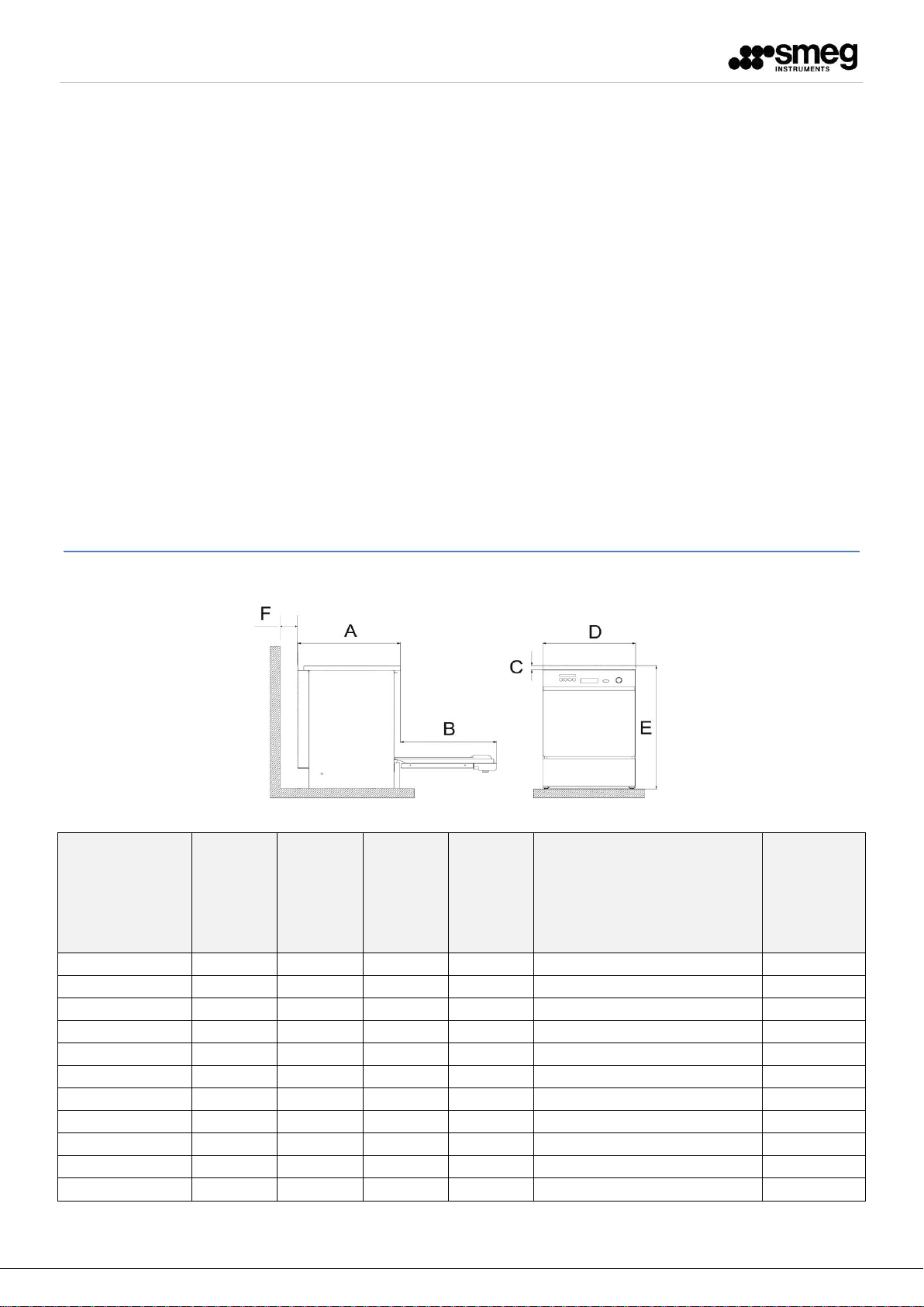
A B C
D
E
(in brackets the height with built-in top)
[Only for the GW0160, GW1160,
GW4060, WD1160, WD4060 series: the
height, with the optional “Aquastop
system”, is indicated between square
brackets]
F
GW2045
620
600
30
450
850 (830)
> 10
GW1060
640
600
30
600
850 (820)
> 10
GW0160
600
600
30
600
850 (820) [857]
> 10
GW1160
600
600
30
600
850 (820) [857]
> 10
GW3060
640
600
30
600
850 (820)
> 10
GW4060
600
600
30
600
850 (820) [857]
> 10
WD2050
640
600
30
450
850 (830)
> 10
WD1050
640
600
30
600
850 (820)
> 10
WD1160
600
600
30
600
850 (820) [857]
> 10
WD3060
640
600
30
600
850 (820)
> 10
WD4060
600
600
30
600
850 (820) [857]
> 10
CONTENTS
INSTALLATION REQUIREMENTS .................................................................................................................................................... 2
1 PRODUCT DIMENSIONS – UNITS IN mm ................................................................................................................................ 2
2 MACHINE POSITIONING ......................................................................................................................................................... 4
3 ELECTRICAL SYSTEM REQUIREMENTS .................................................................................................................................... 5
4 HYDRAULIC ARRANGEMENT .................................................................................................................................................. 7
4.1 WATER FILLING ............................................................................................................................................................. 7
4.1.1 “PAD” ACCESSORY FOR DEMINERALIZED WATER NOT UNDER PRESSURE .............................................................. 9
4.2 WATER DRAIN ............................................................................................................................................................. 10
4.3 STEAM DRAIN CONNECTION - ONLY MODELS SERIES 6090 ....................................................................................... 13
INSTALLATION REQUIREMENTS
1 PRODUCT DIMENSIONS – UNITS IN mm
fig. 1 – Schematic drawing 45CM and 60CM, overall dimensions of the product
2
Page 3
REQUEST FOR START-UP
FAMILY
A B C
D1
D2
E
(in brackets the
height with built-
in top)
F
GW4090
640
600
30
900
600
850 (820)
> 10
GW4190
600
600
30
900
600
850 (820)
> 10
WD4190
600
600
30
900
600
850 (820)
> 10
WD5090
640
600
30
900
600
850 (820)
> 10
FAMILY
A B C
D1
D2
E
F
GW6090
800
980
100
900
750
1900
> 10
GW6090DS
800
980
270
900
750
2020
> 10
GW6090B
800
980
100
900
750
1900
> 10
GW6090BDS
800
980
260
900
750
2010
> 10
WD6090
800
980
100
900
750
1900
> 10
WD6090DS
800
980
270
900
750
2020
> 10
WD6090BDS
800
980
260
900
750
2010
> 10
fig. 2 – Schematic drawing GW4090 and WD5090 overall dimensions of the product 90CM.
fig. 3 – Schematic drawing GW6090 and WD6090, overall dimensions of the product
3
Page 4

REQUEST FOR START-UP
2 MACHINE POSITIONING
IMPORTANT
The machine must be positioned with its back against a wall (minimum distance 10 mm) and must be installed by an
authorized SMEG technician. The machine, when suitably prepared, can be placed under a work top
The technician who installs the machine is responsible for the appliance correct operation after it has been installed. The
technician must also provide all the necessary information to the user for correct use.
During installation, it is necessary to remove the scratchproof film on the outer steel surfaces.
The kit of installation accessories (seals and clamps) is located inside the wash chamber.
The machine can be placed up against the sides to the adjacent units, taking care to leave free venting of the steam on the
back: it is therefore advisable that the wall at the back is made of brickwork or some other impermeable material.
Furthermore ensure the heat does not reach any electrical circuits or sockets on the back of the appliance.
The machine is equipped with hoses to supply and drain off the water. These can be positioned towards the right or left,
depending on the installation requirements.
LEVELLING
After positioning the machine, adjust the feet by screwing or unscrewing them in order to adjust the height and level it using
a spirit level so that it is to be horizontal (max angle tolerance allowed: 0.5°).
Correct levelling will ensure that the machine operates in the right way.
CAUTION
Any adjustment, maintenance, etc.. must be performed with the device switched off and disconnected from power sources.
LIFTING AND TRANSPORT
The base of the machine, before leaving the factory, is fixed on a pallet which serves both for lifting and for the transport.
The machine must be handled with a fork-lift truck or transpallet.
INSTALLATION WITH BASE - MACHINE SUPPORT
If the device is installed on a support (e.g. product Smeg B6040) with height "HB" (base height), all the dimensions of the
height with respect to the support surface outlined in this document are to be increased of the same "HB" amount.
HMi = Hi + HB
Where:
Hi = generic dimension indicated in the document
HB = height of the machine base support
HMi = dimension recalculated for machine installed on the base
fig. 4 – Base Smeg B6040L.
4
Page 5

REQUEST FOR START-UP
CAUTION
It is essential that the electrical system to which the machine is connected complies with current regulations (CEI 64-81).
CAUTION
All electrical testing operations and equipment electrical installation should be made by qualified personnel.
The competent personnel is responsible to check that the earthing is efficient.
FAMILY
VARIANT
(suffix to the model
name)
CONNECTION
DESCRIPTION
REQUIRED PHASES AND
VOLTAGE
MAX POWER
OVERCURRENT PROTECTION
DEVICE
GW2045,
WD2050
ALL MODELS
230V Single phase
230V 1N~ / PE / 50Hz
3.3 kW
Circuit-breaker, 20A installed on
the machine
GW1060,
WD1050,
WD3060
STANDARD (e.g.
WD1050)
Three-phase 400V
400V 3N~ / PE / 50Hz
7.0 kW
Circuit-breaker, 16A installed on
the machine
-3
(e.g. WD1050-3)
230V three phase
without neutral
230V 3~ / PE / 50Hz
7.0 kW
Circuit-breaker, 20A installed on
the machine
-1
(e.g. WD1050-1)
230V Single phase
230V 1N~ / PE / 50Hz
2.8 kW
Circuit-breaker, 16A installed on
the machine
GW0160,
GW1160,
WD1160,
GW4060,
WD4060,
GW4190,
WD4190
STANDARD (es.
WD4060)
Three-phase 400V
400V 3N~ / PE / 50Hz
7.0 kW
Fuses, 16A installed on the
machine
-3
(es.WD4060-3)
230V three phase
without neutral
230V 3~ / PE / 50Hz
7.0 kW
Fuses, 20A installed on the
machine
-1
(es. WD4060-1)
230V Single phase
230V 1N~ / PE / 50Hz
2.8 kW
Fuses, 16A installed on the
machine
GW3060,
GW4090,
WD5090
STANDARD (e.g.
WD4060)
Three-phase 400V
400V 3N~ / PE / 50Hz
7.0 kW
Circuit breaker required on the
building side, [3P+N, 16 A]
-3
(e.g. WD4060-3)
230V three phase
without neutral
230V 3~ / PE / 50Hz
7.0 kW
Circuit breaker required on the
building side, [3P, 20 A]
-1
(e.g. WD4060-1)
230V Single phase
230V 1N~ / PE / 50Hz
2.8 kW
Circuit breaker required on the
building side, [1P+N, 16 A]
GW6090,
WD6090
ALL MODELS
Three-phase 400V
400V 3N~ / PE / 50Hz
18.5 kW
Circuit breaker required on the
building side, [3P+N, 40 A]
1
3 ELECTRICAL SYSTEM REQUIREMENTS
Systems necessary to be installed in the room - see also the manual of the model to be installed.
The machines are designed for connection to the electricity grid with the following voltages (depending on the model
chosen).
CEI 64-8: "Electrical systems using a rated voltage not exceeding 1000 V alternate current and 1500 V direct current." , Part 7: Environments and special
applications. http://www.ceiweb.it/
5
Page 6

REQUEST FOR START-UP
ELECTRICAL CONNECTION
With the exception of “45cm” machines (GW2045 and WD2050 families), the device is supplied
without plug, with cable with pre-insulated terminals pins.
Only The “45cm” machines are supplied with plug (Schuko plug except for the machines for the UK
market, supplied with UK three-pole fuse approved plug).
The electrical connection of the device must be carried out:
1. For all the models of the series GW1060, GW3060, GW4090, GW6090, WD1050, WD3060,
WD5090, WD6090: With a permanent connection.
2. For all the models of the series GW0160, GW1160, WD1160, GW4060, WD4060, GW4190,
WD4190 : With industrial plug. The plug and its installation shall be borne by the user.
3. For the “45cm” machines models: using the supplied plug.
POWER CABLE
Characteristics of the power cable supplied with the equipment:
- FROR 5 x 6 mm
2
, 450/750 V, IMQ mark (GW6090, WD6090 series)
- FROR 5 x 2.5 mm
2
, 450/750 V, IMQ mark (three-phase version)
- FROR 4 x 2.5 mm
2
, 450/750 V, IMQ mark (three-phase without neutral version)
- FROR 3 x 2.5 mm
2
, 450/750 V, IMQ mark (single-phase version)
ELECTRICAL MAINS SWITCH
A disconnecting device, on the building side, shall be provided for every equipment installed.
Disconnecting device characteristics:
1. the disconnecting means shall disconnect all current-carrying conductors
2. it shall be in close proximity to the equipment
3. Il must be easily accessible for the user.
4. it shall be marked as the disconnecting device for the equipment.
OVERCURRENT PROTECION DEVICE
For all the models not provided with an overcurrent protection device, an overcurrent protection
device is required on the building side (circuit breaker or fuses in all supply conductors, calculated
on the basis of the electrical characteristics listed above in the table).
It is always recommended to use an overcurrent protection device for all models.
6
Page 7

REQUEST FOR START-UP
INITIALS
LOAD / UNLOAD
WATER TYPE
cw
FILLING
cold water hose - cw (cold water)
hw
FILLING
hot water hose - hw (hot water)
dw
FILLING
demineralized water hose under pressure - dw (demineralized water)
d
DRAIN
machine drain hose - d (drain)
cd
DRAIN
steam condenser drain hose - cd (condenser drain)
FAMILY
N.
OF FILLING
CONNECTIONS
CONNECTION TYPE
cw
dw
hw
GW2045 xxx
2 1 1
---
GW1060 xxx
2 1 1
---
GW0160 xxx
2 1 1
---
GW1160 xxx
2 1 1
---
GW3060 xxx
3 1 1
1
GW3060 Cxx
3 1 1
1
GW4060 xxx
2 1 1
---
GW4090 Cxx
3 1 1
1
GW4090 Cxx
4 2 1
1
GW4190 xxx
2 1 1
---
GW6090 xxx
3 1 1
1
WD2050 xxx
1 1 ---
---
WD1050 xxx
2 1 1
---
WD1160 xxx
2 1 1
---
WD3060 xxx
4 2 1
1
WD4060 xxx
2 1 1
---
WD4190 xxx
2 1 1
---
WD5090 xxx
3 1 1
1
WD6090 xxx
3 1 1
1
4 HYDRAULIC ARRANGEMENT
Key to abbreviations used for water connections.
4.1 WATER FILLING
WATER INLETS CONNECTION
The machine is equipped with one or filling hoses, depending on the type of model.
The hoses are designed to be connected to taps with 3/4'' gas threaded bushing.
Use the filter provided, "A" in the image, when connecting the ends of the filling hose.
fig. 5 – When connecting the filling hose install the filters provided.
Product "families" note
The suffix "C" indicates "equipped with steam condenser."
Any additional suffixes ".." can take on different values depending on the configuration of the machine.
7
Page 8

REQUEST FOR START-UP
FILLING TAPS POSITIONING
The taps for the water filling must be positioned close to the appliance, in a position accessible to the user. With reference to
the following figure, the values recommended are:
I < 50 cm HC < 80 cm
fig. 6 – Schematic drawing. The filling connections can be provided on the right or left side of the appliance, always taking into account the maximum
Note to prevent the risk of clogging or damage: if the water pipe is new or has been inactive for a long time, before
connecting the water supply make sure that the water is clear and free of impurities.
CAUTION
If there is not a double hot/cold water supply, the two supply hoses (cold and hot) must be connected together through a
special Y (see image below).
distance indicated by the product “I”.
SYSTEM REQUIREMENTS
Ensure that:
1. the water supply pressure is within the required limits: min. 2 bar - max 5 bar.
2. The hot water temperature must not be higher than 50 ° C - Higher temperatures may damage the efficiency of the
water softener incorporated causing damage to the resins contained in it.
3. The water supply taps must be accessible.
CHARACTERISTICS OF WATER SUPPLY
Cw: WATER MAINS - essential:
For the operation of the machine it is required that the connection is to a water mains of "drinkable" quality having a
hardness of max. of 42°f (8°f for GW6090 and WD6090) and with the total content of dissolved iron, Fe2+ and Fe3+, not
greater than 0.5 ppm.
fig. 7 – "Y" connection of the water filling with filters positioning.
8
Page 9

REQUEST FOR START-UP
WARNING - NO DEMINERALIZED WATER
If demineralized water is not available on the system, do not connect the related hose to cold
and/or hot water inlet taps. Leave the "demineralized water" hose not connected.
It is necessary to adequately correct the machine SETTINGS - by the Authorized Service Center.
FAMILY
TYPE OF PAD WHICH CAN BE USED
"GROUND" TANK
"RAISED" TANK
GW2045
-
PAD1
GW1060
PAD2 + PAD2R
PAD
GW0160
PAD2 + PAD2R
PAD1
GW1160
PAD2 + PAD2R
PAD1
GW3060
PAD2
PAD
GW4060
PAD2 + PAD2R
PAD1
GW4090
PAD2
PAD
GW4190
PAD2 + PAD2R
PAD1
GW6090
PAD2
-
WD2050
- - WD1050
PAD2 + PAD2R
PAD
WD1160
PAD2 + PAD2R
PAD1
WD3060
- - WD4060
PAD2 + PAD2R
PAD1
WD4190
PAD2 + PAD2R
PAD1
WD5090
- - WD6090
PAD2
-
Hw: HOT MAINS WATER - optional and available only on some models:
Connection to a water mains of "drinkable" quality having a hardness of max. 42°F (8°f for GW6090 and WD6090) and with
the total content of dissolved iron expressed as Fe2+ and (+) Fe3+ not greater than 0.5 ppm.
The hot water temperature must not exceed 50°C.
NOTE
In case the water supply contains iron Fe2+/Fe3+ in a quantity exceeding 0.5 ppm and / or the supply water has a hardness
greater than 42°f (French degrees) it is necessary to undertake a pretreatment of the water by installing upstream an iron
removal and/or softening system.
Models GW6090 and WD6090 do not have an integrated softener: the maximum water hardness allowed is therefore 8°f.
Dw: DEMINERALIZED WATER- optional (highly recommended):
If available, the demineralized water (conductivity < 30 µS) is recommended to have an optimal washing from the chemical
point of view, for a better elimination of the residues of the salts present in the water supply mains; the lack of this
connection does not affect the removal of dirt.
4.1.1 “PAD” ACCESSORY FOR DEMINERALIZED WATER NOT UNDER PRESSURE
The connection to a line of demineralized water not under pressure (e.g. gravity tank), is possible only by installing a special
booster pump.
Each model must be equipped with its own specific pump - see table below.
This pump ensures that the demineralized water enters with sufficient pressure for proper operation of the machine.
The PAD and PAD1 accessories are mounted externally and hooked on the back of the machine.
The PAD2 accessory is mounted outside the appliance. On certain models the PAD2 requires necessarily the use of
the kit “PAD2R”, see the Table below.
9
Page 10

REQUEST FOR START-UP
CAUTION
- FOR THE INSTALLATION OF "PAD" and "PAD1" MAKE SURE THAT:
The supply pressure of the PAD is less than 1 bar and greater than 0.1 bar.
- "PAD" and "PAD1" IN COMBINATION WITH TANK NOT UNDER PRESSURE
With reference to the following image, the tank must be at a distance L such that:
L > 100 cm
The value represents the distance between the support surface of the machine and the lower
support surface of the tank. This height ensures an inlet pressure to the PAD of approximately 0.1
bar.
- "PAD2" IN COMBINATION WITH A TANK NOT UNDER PRESSURE
With the installation of PAD2, the tank not under pressure can be at the same level of the support
surface of the appliance, with reference to figure L ≥ 0.
fig. 8 – Tank not under pressure, height with respect to the supporting surface of the device.
4.2 WATER DRAIN
Drain hoses of the machine:
Rubber terminal with hose connector diameter 21mm (1/2").
WATER DRAIN CONNECTION
The machine is equipped with one or more drain hoses, depending on the model.
The drain hoses are referred to as:
- d - machine drain hose – d (drain)
- cd - steam condenser drain hose (not always installed) – cd (condenser drain)
The chart and summary table are shown below.
10
Page 11

REQUEST FOR START-UP
FAMILIES
N. OF DRAIN
HOSES
Dimension "I"
Max. Distance of the drain from
the appliance side [cm]
DRAIN TYPE AND "H" DIMENSION
FROM THE SUPPORT SURFACE OF THE
MACHINE [cm]
Type
Hmin
Hmax
GW2045 xxx,
GW1060 xxx
1
50
d
40
80
GW1060 C xx 2 50
d
40
80
cd
65
80
GW0160 xxx,
GW1160 xxx,
GW3060 xxx,
GW4060 xxx,
GW4090 xxx,
GW4190 xxx
1
50
d
65
80
GW1160 C xx
GW3060 C xx,
GW4090 C xx,
GW4190 C xx
2
50
d
65
80
cd
65
80
GW6090 xxx 1 50
d
95
105
WD2050 xxx 1 50
d
15
60
WD1050 xxx 2 50
d
40
80
cd
65
80
WD1160 xxx,
WD3060 xxx,
WD4060 xxx,
WD4190 xxx,
WD5090 xxx
2
50
d
65
80
cd
65
80
WD6090 xxx 1 50
d
95
105
fig. 9 – Schematic drawing. The hydraulic drain connections can be arranged on the right or left of the unit, always taking into account the maximum distance
indicated by the product “I”.
Dimension “I” – the distance of the drain from the appliance side, for all the models, must be:
I <50 cm
Product "families" note
The suffix "C" indicates "equipped with steam condenser."
Any additional suffixes ".." can take on different values depending on the configuration of the machine.
11
Page 12

REQUEST FOR START-UP
CAUTION
The dimension “H in the figure must always be within the limits shown in the table: Hmin and
Hmax (for example for WD2050: Hmin=15cm, Hmax=60cm).
Dimension "X": The dimension "X" between the discharge connection and the highest part of the
tube should always be less than 20cm: X < 20cm.
Use only original Smeg parts.
CAUTION
The drain must comply with international regulations: our company accepts no liability for
pollution caused by improper use of the appliance.
fig. 10 – Drain connection.
fig. 11 – Adapter with connector for 1/2" hose.
General guidelines for installing the drain
The use of an drain with syphon is recommended. During the installation procedure, the following precautions should be
observed:
Since the temperature of drain water is 95°C, the end of the drain hose must be installed permanently to the hose
connector, using the straps provided.
The drain hose must not have sharp bends leading to bottlenecks.
The end of the drain hose must be placed, with respect to the support surface of the machine, at a height conforming to
the specifications.
In no event the end of the hose shall be submerged in water.
The inner diameter of the drain duct must be at least 40 mm.
It is recommended to install a drain duct with 50 mm diameter.
Extensions must not be made on the drain hose that comes with the machine. Any extensions may cause reflux problems
in the tank.
12
Page 13

REQUEST FOR START-UP
Air / steam drain
Connection Type
Two stainless steel Ducts Outer diam. = 40mm - high side,
on the back
Air flow
Max 300 m³/h
Temperature
Max 110°C
4.3 STEAM DRAIN CONNECTION - ONLY MODELS SERIES 6090
The machine is fitted with double steam drain duct.
The environments must be prepared to connect the drain ducts of the machine, located at the top of the appliance.
Note
The drain ducts protrude over the maximum “E” height, indicated in the "PRODUCT DIMENSIONS" table, of 3 cm.
fig. 12 – Top view. Position of the two drain ducts, upper part, top view of the machine. Dimensions in mm.
Smeg S.p.A.
Via Leonardo da Vinci, 4 – 42016 Guastalla (RE) - Italy
Tel. +39 0522 8211 – Fax +39 0522 821 592
E-mail: instruments@smeg.it – www.smeg-instruments.com
Instruments Division
13
 Loading...