

Page 1
Rev. 01
Man. WD1050
Pag. 1 - 40
The machine must only be installed, serviced and repaired by
authorized personnel.
The warranty could become void if the machine is used in a way
that Fails to Conform to the instructions given by SMEG.
19 390 2191 01
02/03/2011
Rev.
Date
READ THE INSTRUCTIONS MANUAL CAREFULLY
Failure to read the manual, misunderstandings or incorrect interpretation of the
instructions herein may result in damage to the appliance. Moreover, such action may
also become a source of danger for the user and considerably lower the performances
of the machine.
The manufacturer declines all liability for use of the machine
differing from that described in this manual.
The text and illustrations in this manual are for informative purposes only. The
contents and appliance described herein may be liable to modification without prior
notice. In no case may SMEG be held liable for any direct or indirect damages deriving
from or in relation to use of this manual.
Page 2
Rev. 01
Man. WD1050
Pag. 2 - 40
Information or Assistance for products from the
SMEG Instruments Division
If so, please contact us from 8 a.m. until 6 p.m. at the following numbers and
addresses:
www.smeg-instrumens.com
instruments@smeg.it
Fax +39 0522 821 592
Tel +39 0522 8211
Our Sales Office staff will give you all the info you require about prices and
offers. You can also view our entire production range in our web site along with any
innovations.
Our Technical Assistance Office staff can tell you how to operate your appliance
in the correct way or put you in contact with your nearest Authorized Assistance
Centre if necessary.
International customers, please contact your local SMEG distributor.
Page 3
Rev. 01
Man. WD1050
Pag. 3 - 40
TABLE OF CONTENTS
1. INTRODUCTION ................................................................................................ 5
2. SYMBOLS LEGEND .......................................................................................... 6
3. GENERAL RECOMMENDATIONS ..................................................................... 6
4. GENERAL SPECIFICATIONS ............................................................................ 8
4.1. TECHNICAL FEATURES ................................ ............................................................. 8
4.2. LIFTING AND HANDLING ............................................................................................ 9
4.3. DOOR LOCKING SYSTEM .......................................................................................... 9
4.4. MANUAL DOOR UNLOCKING ................................................................................... 10
5. INSTALLATION ............................................................................................... 11
5.1. POSITIONING ........................................................................................................... 11
5.2. LEVELLING ............................................................................................................... 11
5.3. CONNECTION TO WATER MAINS ............................................................................ 12
5.4. WATER SUPPLY ....................................................................................................... 13
5.5. NON PRESSURIZED DEMINERALIZED WATER CONNECTION ................................ 14
5.6. WATER DRAIN CONNECTION .................................................................................. 15
5.7. ELECTRICAL CONNECTION ..................................................................................... 16
6. DESCRIPTION OF CONTROLS ....................................................................... 17
6.1. SETUP DESCRIPTION .............................................................................................. 18
6.2. WASHING PROGRAMME SETTINGS ........................................................................ 20
6.3. THERMAL DISINFECTION IN ACCORDANCE WITH THE PARAMETER "A0" ............. 20
6.4. PROGRAMMES DESCRIPTION ................................................................................ 22
6.5. MACHINE RUNNING ................................................................................................. 23
6.6. RESIN WASHING PHASE ................................ ......................................................... 24
6.7. RESIN REGENERATION PHASE ............................................................................... 24
6.8. PROGRAMME TERMINATION .................................................................................. 24
6.9. IN PROGRESS PROGRAMME INTERRUPTION ........................................................ 24
6.10. RESET PROCEDURE.............................................................................................. 24
6.11. DATE AND TIME SETUP ......................................................................................... 25
6.12. DEMI WATER SETTING .......................................................................................... 26
6.13. PRINTER ................................................................................................................ 26
6.14. PRINTER LANGUAGE ............................................................................................. 27
7. OPERATING INSTRUCTIONS ......................................................................... 28
7.1. USE OF THE WATER SOFTENER ............................................................................. 28
7.2. USE OF THE DETERGENT AND NEUTRALIZING AGENT ......................................... 29
7.3. DETERGENT AND NEUTRALIZING AGENT RECOMMENDED BY SMEG .................. 29
8. ALARMS .......................................................................................................... 31
9. CLEANING AND MAINTENANCE .................................................................... 34
9.1. RECOMMENDATIONS AND GENERAL ADVICE ........................................................ 34
9.2. IF THE INSTRUMENT WASHER IS NOT USED FOR A LONG PERIOD OF TIME ........ 37
9.3. REUSE OF THE INSTRUMENT WASHER AFTER A LONG PERIOD OF INACTIVITY . 37
9.4. TROUBLESHOOTING ............................................................................................... 37
Page 4

Rev. 01
Man. WD1050
Pag. 4 - 40
10. ROUTINE CHECKS ................................................................ ......................... 39
10.1. DAYLY .................................................................................................................... 39
10.2. WEEKLY ................................................................................................................. 39
10.3. HALF YEARLY ........................................................................................................ 39
10.4. YEARLY .................................................................................................................. 39
11. WD1050 DIMENSIONS .................................................................................... 40
Page 5
Rev. 01
Man. WD1050
Pag. 5 - 40
The instrument washer complies with all the requisites established by
the current safety standards governing electrical equipment. Technical
inspections must only be made by specialized and authorized
personnel.
BESIDES VOIDING THE WARRANTY, REPAIRS MADE BY
UNAUTHORIZED PERSONNEL MAY REPRESENT A DANGER
HAZARD FOR THE USER.
1. INTRODUCTION
This manual is an integral part of the machine.
It must be kept in a good condition and ready to hand for the entire life cycle of the
machine. We advise you to carefully read this manual and all the instructions it
contains before using the appliance.
This appliance conforms to the EEC Directive 2007/47 currently in force.
The appliance has been made in order to:
- wash Surgical and Dental Instruments with Thermal Disinfection1;
- the appliance cannot be used to sterilize instruments or any other device.
All other uses are considered improper.
The manufacturer declines all liability for uses differing from those indicated.
The manufacturer declines all responsibility for any possible damage caused by
the washing of instruments whose manufacturers have not authorized to be
automatically decontaminated.
1
Treatment in the Instrument Washer can never be a substitute for sterilizing. Disinfection in the instrument
washer is carried out to reduce the risks sustained by the persons who handle surgical instruments when
preparing them for sterilization and to guarantee a better successive sterilization process.
Page 6
Rev. 01
Man. WD1050
Pag. 6 - 40
Carefully read the paragraph.
Attention, Danger, see the manual.
Attention, hot surface.
~
Alternating current.
CE mark, notified body: IMQ.
At the end of life the product should be sent to disposal facilities for the recovery and
recycling.
Never use solvents such as alcohol or turpentine in the appliance as
they could cause an explosion. Never put instruments dirtied with ash,
wax or paint in the appliance.
2. SYMBOLS LEGEND
3. GENERAL RECOMMENDATIONS
Do not rest or sit on the open door of the instrument washer as this could cause the
appliance to overturn and thus represent a danger hazard for persons. The
maximum weight loaded onto the open door, including the weight of the instrument
trolley, must never exceed 30kg.
Page 7
Rev. 01
Man. WD1050
Pag. 7 - 40
Only open the door after the washing cycle has terminated.
If you open the door while a programme is in progress, hot water, steam
and other liquids will spill out and may injure the user. Only authorized
and well-informed personnel are allowed to use the machine.
Never ever touch the heating element immediately after a washing cycle has
terminated.
The heating element could become slightly darkened during use of the instrument
washer, even to a localized extent. This should be considered normal as it depends
on the operating mode and does not impair the way the appliance works.
At the end of its working life, the appliance must be rendered unusable. Cut off the
power flex after having removed the plug from the power socket. The appliance
must then be consigned to an authorized disposal center.
If the appliance operates in a faulty way, unplug it from the electricity main, shut off
the water cock and contact your nearest authorized Assistance Center.
Page 8
Rev. 01
Man. WD1050
Pag. 8 - 40
MODELS
WD1050
WD1050-3
WD1050-1
ELECTRIC POWER SUPPLY
VERSION
Triphase 400V
Trifase 230V
Monophase 230V
TYPE OF VOLTAGE
[tolerated variation 10%]
400V 3/N/E
230V 3/PE
230V 1/N/PE
FREQUENCY [H Z]
50
POWER RATING [KW]
7 kW
7 kW
2,8 kW
AUTOMATIC SWITCH ON
MACHINE
In 16 A 3P+N 400V
Icn 4500 A
In 20A 3P 400V Icn
6000 A
In 16 A P+N 230V
Icn 4500 A
WATER SUPPLY
TYPE OF WATER
COLD WATER
DEMINERALISED WATER
PRESSURE [BAR ]
2 – 5
2 – 5
TYPE OF CONNECTION
3/4"
3/4"
MAX HARDNESS [°F] /
CONDUCTIVITY[S/CM ]
42°F
Max 20μS
IRON [PPM] FE MAX
< 0.5
DRAIN
FROM FLOOR LEVEL (on which machine is placed)
HEIGHT [MM]
Min 650 - Max 800
DIAMETER [MM]
Min 40
DIMENSIONS
HEIGHT
850
DEPTH
670
WIDTH
600
NET WEIGHT [KG]
65
Material used
Washing chamber AISI 316L
External cladding AISI 304
ENVIRONMENTAL CONDITIONS
USE
Indoor
ALTITUDE
Up to 1000m
TEMPERATURE
From 5°C to 40°C
RELATIVE HUMIDITY
80% for temperatures up to 31°C with linear diminution down to 50%
at the temperature of 40°C
INSTALLATION CATEGORY
II
CLASS TO WHICH
APPLIANCE BELONGS
IIb (in compliance with the classification criteria established by DIRECTIVE
2007/47)
POLLUTION DEGREE
2
4. GENERAL SPECIFICATIONS
4.1. TECHNICAL FEATURES
Page 9
Rev. 01
Man. WD1050
Pag. 9 - 40
Before it leaves the factory, the base of the machine is fixed to a pallet
which is then used to lift and transport the machine itself.
The machine must be handled with a fork-lift truck or transpallet.
Do not use appliances damaged by transport! Consult your dealer if in
doubt.
The appliance must only be installed and connected by personnel
authorized by the manufacturer.
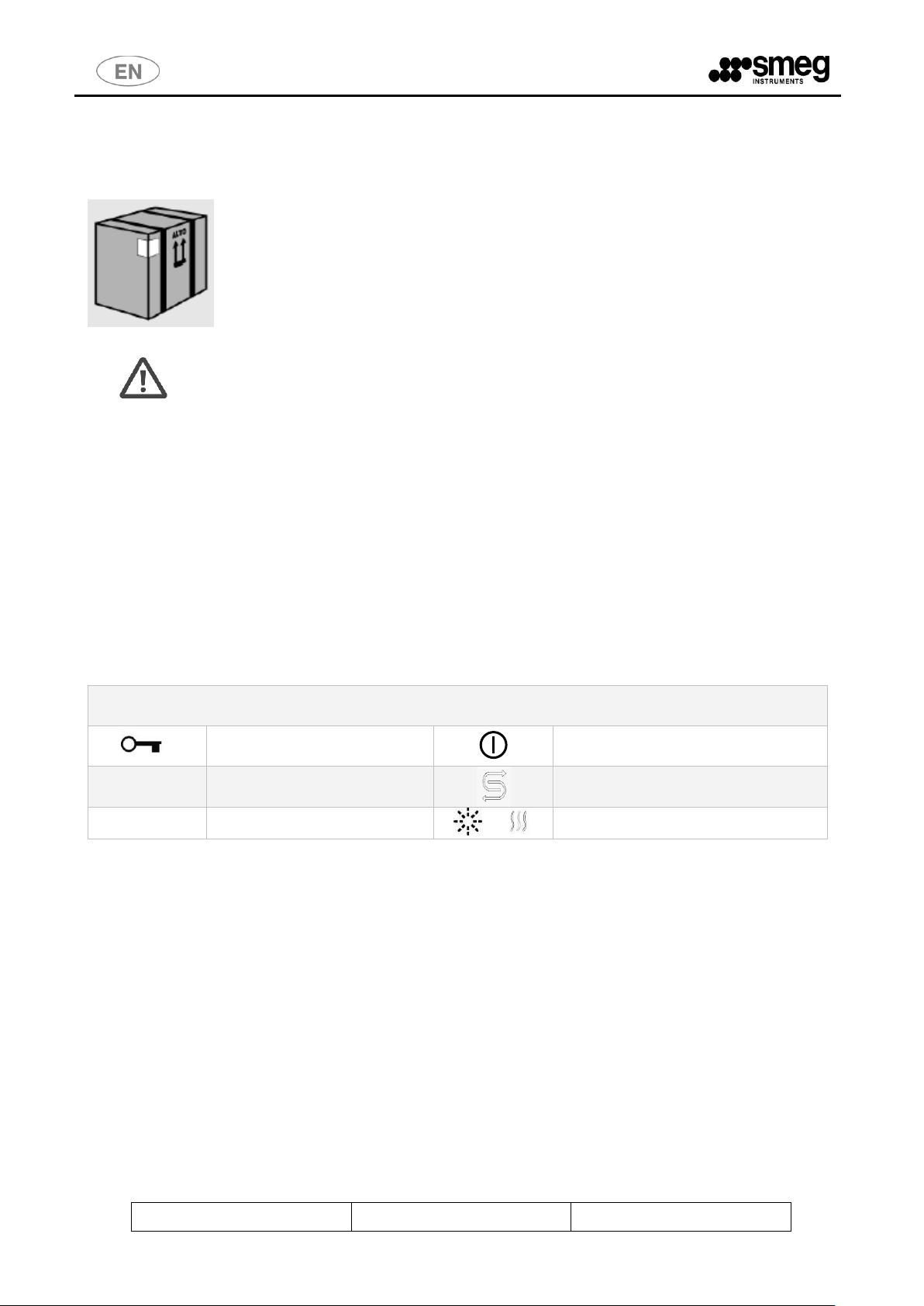
SIGNS ON THE FRONT OF THE MACHINE
Door unlocking
ON / OFF
°C
Temperature
Salt Lack
► ll
START / PAUSE
or
Heating element on
4.2. LIFTING AND HANDLING
4.3. DOOR LOCKING SYSTEM
After unpacking, pay attention to the following:
the machine is equipped with an automatic door locking/unlocking system.
The door is locked. Don‟t force the door, but follow the procedure below.
Connect the machine to the mains supply;
push the ON/OFF button (in order to switch on the machine)
push (and hold) the button with the symbol of the key and after some seconds the
door opens
Page 10
Rev. 01
Man. WD1050
Pag. 10 - 40
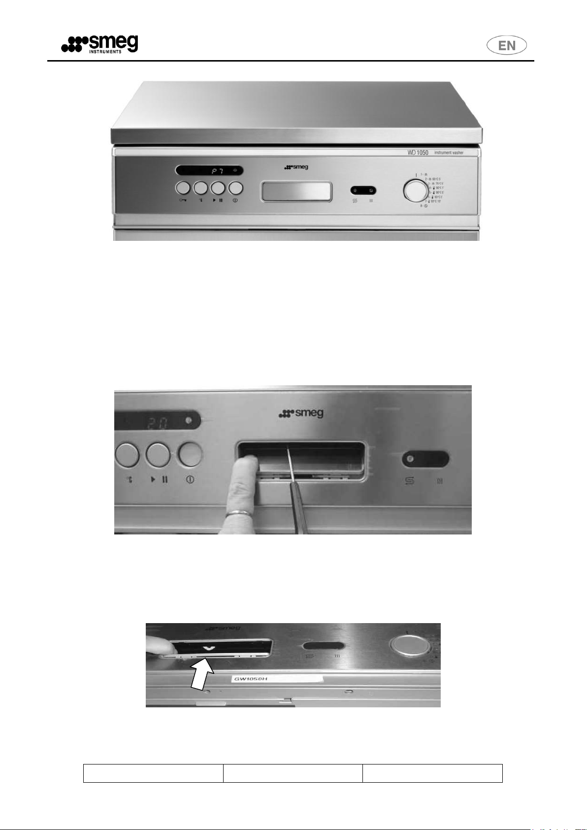
fig. 1 – WD1050 front.
In order to open the door without connecting the machine to the mains, the manual
unlocking procedure must be executed. Please, see the following paragraph for further
details.
4.4. MANUAL DOOR UNLOCKING
In case of emergency or in case of a power failure the door may be manually opened
inserting a small screwdriver under the handle, as shown on the image.
fig. 2 – WD1050 front. To unlock the door manually: 1 - push the handle opening to access the opening
mechanism, 2 - Force, pushing it from bottom to top, with a small screwdriver the opening mechanism.
Insert the screwdriver carefully into the yellow marked hole till the characteristic
“CLACK” is heard.
Page 11
Rev. 01
Man. WD1050
Pag. 11 - 40
IMPORTANT: The machine must be positioned against the wall
(minimum distance 10 cm) and must be installed by a technician
authorized by the manufacturer.
The technician who installs the machine is responsible for the
appliance operating correctly after it has been installed. He is also
obliged to provide the user with all the information required to use
the machine in the correct way.
All adjustments, servicing and so forth, must be carried out with the
appliance disconnected from the electricity main.
The scratch-proof film must be removed from the external steel
surfaces when the appliance is installed.
IT IS STRICTLY FORBIDDEN FOR UNAUTHORIZED PERSONS TO
USE THE MACHINE.
5. INSTALLATION
5.1. POSITIONING
The side panels of the machine must adhere to the adjacent furniture and care must
be taken to leave space at the rear: it is therefore advisable for the wall at the back to
be made of brickwork or some other impermeable material.
The machine has pipes to supply and drain off the water. These can be positioned
towards the right or left, depending on the installation requirements.
The machine can also be installed under a work top: this operation must be carried out
by specialized personnel.
5.2. LEVELLING
Once the machine has been set in position, it must be levelled until horizontal (2
degrees tolerance allowed) by either screwing in the feet or unscrewing them.
Correct levelling will ensure that the machine operates in the right way.
Page 12
Rev. 01
Man. WD1050
Pag. 12 - 40
WARNING
Make sure that the inlet pressure of the mains water is within the
operating limits: min. 2 bar - max 5 bar.
The water shutoff valves must be accessible
CAUTION
Chemical characteristics of mains water that are not compatible
with a good washing process.
If the water contains more than 0.5 ppm of iron Fe2+/Fe3+ and/or the
hardness of the water is more than 42°F (French degrees), it must be
pre-treated by installing a deferrization and/or softening system
upstream.
5.3. CONNECTION TO WATER MAINS
Prevent the risk of clogging or damage to the appliance: if the water pipe is new or has
remained unused for a long period of time, make sure that the water is limpid and free
from impurities before connecting the machine to the water main.
The pipe is pre-engineered for connection to a cock with 3/4‟‟ gas threaded union on
both ends.
Insert the supplied filters "A" before connecting the other ends of the pipes to their
respective cocks.
It is advisable to allow the water to run in order to drain off any rusty deposits or
sludge if connections are made with new pipes.
In case of blood-stained instruments make sure that the machine is not supplied with
water at temperature higher than 40°C.
Always shut off the water supply cocks when the machine is not being used
Page 13

Rev. 01
Man. WD1050
Pag. 13 - 40
If demineralized water isn't available: don't connect the demi pipe
to the cold or hot water, leave it disconnected and see the
instructions (paragraph "DEMI WATER SETTINGS" 6.12) in order to
set correctly the demi water parameter.
5.4. WATER SUPPLY
The machine is supplied with two water supply pipes that join to a non-return device
inside the machine.
The pipes are designed for connection to cocks with 3/4” gas threaded bushings.
The following pipes (see the picture below) must be connected to water mains:
cold water pipe;
pressurized demineralized water pipe (min. 2 bar - max. 5 bar) – if present.
fig. 3 – Back view of the machine
Page 14

Rev. 01
Man. WD1050
Pag. 14 - 40
If the PAD pump is used, the water supply pressure must be less
than 1 bar.
WARNING
Make sure that the demineralized water pressure is less than or
equal to 1bar. The manufacturer declines every responsibility for
higher pressures.
5.5. NON PRESSURIZED DEMINERALIZED WATER CONNECTION
The connection to a non-pressurized demineralized water supply (e.g. gravity tank) is
possible only by installing the special demineralized water pump, called "PAD5".
The PAD, optional booster pump, ensures the correct inlet water supply pressure
within the pre-set filling time.
This accessory can be fitted on any machine and must be mounted on the back of the
machine.
We advise having the pump installed by a specialized technician, who should follow
the instructions provided.
The manufacturer will accept no responsibility for any possible damage caused
by an incorrect installation performed by an unauthorized technician.
Page 15

Rev. 01
Man. WD1050
Pag. 15 - 40
WARNING
The drain connection must comply with international standards.
Our company will accept no liability for pollution caused by the
machine..
5.6. WATER DRAIN CONNECTION
This machine has just one outlet hose.
The internal diameter of the hose is ½” so it can be connected to any standard ½”
hose adapter.
General rules for installing outlet
The washing water outlet hose must be placed with its curved section hooked onto the
edge of a sink or waste pipe. A drain pipe with siphon should be used.
The following precautions should be observed during installation:
As the water drain temperature may reach about 93°C the end of the outlet hose
must be connected firmly to the drain by using clamps.
The outlet hose must not have any tight bends liable to obstruct the flow;
The end of the outlet hose must not be placed either more than 80cm or less than
65 cm above the surface on which the machine is installed;
The end of the hose must under no circumstances be immersed in water;
The internal diameter of the waste pipe must be at least Ø 40 mm;
We recommend installing a waste pipe of diameter 50 mm;
Don't use waste pipe extensions.
fig. 4 – 65 cm < A < 80 cm
Page 16

Rev. 01
Man. WD1050
Pag. 16 - 40
WARNING
The machine is equipped with a power cable for permanent connection to the
electrical power supply.
A switch (or circuit breaker) shall be prepared as the means for
disconnection:
1. Il must be easily accessible for the user.
2. It shall be in close proximity to the equipment.
3. It shall be marked as the disconnecting device for the equipment.
WARNING
It is essential for the electricity mains to which the machine is connected to
comply with the current standards in force (CEI 64-8/7;V2 standards).
Always make sure that the ground connection is efficient.
Our company declines all liability for damage caused by connection to a
defective socket that fails to ensure a perfect connection to the general earth
conductor, or by a poorly efficient grounding circuit.
5.7. ELECTRICAL CONNECTION
The machine is designed for connection to an electricity main with the following
voltage rating:
WD1050 ~ 230V 3 / N / PE 50Hz.
There is also a single-phase and 230V three-phase "without neutral", with the following
electrical characteristics:
WD1050-1 ~ 230V 1 / N / PE 50Hz.
WD1050-3 ~ 230V 3 / PE 50Hz.
Page 17

Rev. 01
Man. WD1050
Pag. 17 - 40
ID
DESCRIPTION
1
WASHING PROGRAMME SELECTOR
2
RECESSED HANDLE TO OPEN the DOOR
3
ON/OFF KEY
4
START/PAUSE KEY
5
TEMPERATURE DISPLAY KEY
6
DOOR UNLOCKING KEY
7
THERMODISINFECTION PHASE INDICATOR LIGHT
8
TEMPERATURE DISPLAY INDICATOR LIGHT
9
CYCLE INFORMATION DISPLAY
10
“POWER ON” INDICATOR LIGHT
11
“LACK OF SALT” INDICATOR LIGHT
12
"HEATING ON" INDICATOR LIGHT
SYMBOLS ON THE FRONT PANEL
DOOR UNLOCKING
ON/OFF
°C
TEMPERATURE
LACK of SALT
► ll
START / PAUSE
HEATING ELEMENT ON
6. DESCRIPTION OF CONTROLS
All the controls and indicators of the instrument washer are positioned on the front
panel.
Page 18

Rev. 01
Man. WD1050
Pag. 18 - 40
The new "SETUP" functions are accessible via the program selection process, with
similar procedures to those already used for making the date settings (see also the
user manual, paragraph entitled "SETTING THE TIME AND DATE").
6.1. SETUP DESCRIPTION
Note: Hereafter, in parentheses, we refer to the indices used in the figure to identify
the control elements.
Procedure for accessing the machine "SETUP" menu (common to both models
WD1050 and WD2050, accessible only if no other washing program is running):
Press the ON / OFF key (3) to switch the machine on.
Turn the PROGRAM SELECTOR (1) to the "SETUP" of interest (see below).
Press UNLOCK DOOR (6) and hold for 4 seconds to access the setup function.
You will hear a double beep as confirmation.
To increase the setting press TEMPERATURE DISPLAY (5). Do not use this
key if you only want to display the parameter without editing it.
To decrease the setting press START / PAUSE (4). Do not use this key if you
only want to display the parameter without editing it.
TO TERMINATE PROGRAMMING, press UNLOCK DOOR (6) and hold for 4
seconds. The settings will be saved.
TO EXIT THE "SETUP" MODE WITHOUT SAVING any settings you have
edited, do not press UNLOCK DOOR (6) but simply switch off the machine
using the ON / OFF key (3).
Page 19

Rev. 01
Man. WD1050
Pag. 19 - 40
Language
selected
German
French
Spanish
Italian
English
Code
displayed
dE
Fr
ES
It
En
Connection to demineralized water
Present
Absent:
Code displayed
dn
--
Field
setting
Year
month
Day
Hour
Minutes
Seconds
Position
not used
Position
not used
Position
selector
1 2 3 4 5 6 7
8
SETUP MENU
"SETUP" menu, functions available:
1. Position 1: relative to detergent dosage by pump P1, to set in ml/liter the
dose of detergent with maximum threshold of 20ml/liter. 1 ml steps
(increase/decrease using keys (5) and (4). Default setting P1: 5 ml/l.
2. Position 2: same as Position 1 for P2, neutralizer. Default setting P2: 3 ml/l.
3. Position 3: same as Position 1 for P3. Default setting P3 and 0 ml/l. Function
not present by default on models WD1050 and WD2050.
4. Position 4: setting for hardness of input water in °F, from 5 to 60 with 5°F
steps. By default, hardness is considered 40°F. This parameter is important for
correct function of the water softener incorporated in the equipment.
5. Position 5: selection for automatic door opening at end of cycle. Default
setting is "ON". The segmented display will show "ON" and "OFF" respectively
to select between the two.
6. Position 6: printer language selecting among the different languages
available, default is English.
7. Position 7: connection to demineralized water, yes/no (default is "yes" on
WD1050, "no" on WD2050, which does not have this function).
8. Position 8: Date-time (setting already made, for the details see the user
manual, paragraph entitled "SETTING THE TIME AND DATE").
With the program selector and using keys (5) and (4) you can access and edit
the following parameters:
Page 20

Rev. 01
Man. WD1050
Pag. 20 - 40
6.2. WASHING PROGRAMME SETTINGS
The instrument washer has a practical display that provides all the information the
user needs to know about the functions programmed.
Consult the following table to select the required programme. It gives the washing
cycle most able to suit the nature of the instruments you need to wash and the degree
of dirt involved.
Once you have found the most suitable washing programme in the table, turn the
PROGRAMME SELECTOR knob and select the desired programme by setting it to the
relative reference number.
The following is an indicative list of the type of washing cycles to which the available
programmes refer:
1. Quick washing programme using cold water.
2. Washing programme at 60°C suitable for plastic ware.
3. Washing programme at 75°C suitable for standard glassware.
4. Washing + disinfection at 90°C for 1‟ (A0 =600).
5. Washing + disinfection at 90°C for 5‟ (A0 =3.000).
6. Washing + disinfection at 93°C for 5‟ (A0 =6.000).
7. Washing + disinfection at 93°C for10‟ (A0 =12.000).
8. Service programme: to test the detergent and neutralizer dispensers and rinse the
washing chamber.
6.3. THERMAL DISINFECTION IN ACCORDANCE WITH THE PARAMETER "A0"
We introduce the "A0 concept" to explain the time/temperature relationship used to
draw up the programmes.
According to EN ISO 15883 and the recommendations of the Robert Koch Institute
(European authority on the subject), an A0 of 600 is considered as the minimum
standard for non-critical medical devices, i.e. for those that only come into contact with
uninjured skin. A further condition required is that microbic contamination must only be
slight and there must be no heat-resistant pathogens present.
An A0 value of 600 can be obtained by maintaining a temperature of 80°C for 10
minutes or 90°C for 1 minute or again, 70°C for 100 minutes.
If the medical devices are contaminated with heat-resistant viruses, such as those of
hepatitis B, the value of A0 must be at least 3000. This can be obtained by
maintaining a temperature of 90°C for 5 minutes.
An A0 value of 3000 is considered the minimum value to apply to all medical devices
considered to be critical.
Programmes that include thermal disinfection have therefore been designed to offer
the following A0 values:
Page 21

Rev. 01
Man. WD1050
Pag. 21 - 40
Temperature – time
A0
90°C 1‟
600
90°C 5‟
3000
93°C 5‟
6000
93°C 10‟
12000
10
80
0
10
T
A
T
The approximated formula to calculate A0 is given as follows:
where:
= holding time in seconds at the disinfection temperature.
= disinfection temperature in Celsius degrees.
Page 22

Rev. 01
Man. WD1050
Pag. 22 - 40
PROGR.
PROGRAMME
NAME
PHASE 0
PHASE 1
PHASE 2
PHASE 3
PHASE 4
CYCLE
TIME
1
PREWASH
RINSING
WITH MAINS
WATER FOR
2‟
- - -
-
6‟
2
WASH 60°C – 5'
RINSING
WITH MAINS
WATER FOR
3‟
WASHING
WITH MAINS
WATER
60°C/3‟ AND
DETERGENT
P1
NEUTRALIZIN
G WITH ACID
AGENT 3‟ – P2
RINSING WITH
MAINS WATER
60°C 2'
-
50‟
3
WASH 75°C – 5'
RINSING
WITH MAINS
WATER FOR
3‟
WASHING
WITH MAINS
WATER
60°C/4‟ AND
DETERGENT
P1
NEUTRALIZIN
G WITH ACID
AGENT 1‟ – P2
RINSING WITH
MAINS WATER
75°C AT 5‟
-
55‟
4
THERMAL
DISINFECTION 90°C
1’ (A0=600)
RINSING
WITH MAINS
WATER FOR
3‟
WASHING
WITH MAINS
WATER
60°C/5‟ AND
DETERGENT
P1
NEUTRALIZIN
G WITH ACID
AGENT 1‟ – P2
THERMAL-
DISINFECTION
WITH DEMI
WATER AT
90°C/1‟
-
55‟
5
THERMAL-
DISINFECTION 90°C
5’ (A0=3000)
RINSING
WITH MAINS
WATER FOR
3‟
WASHING
WITH MAINS
WATER
60°C/3‟ AND
DETERGENT
– P1
NEUTRALIZIN
G WITH ACID
AGENT 1‟ – P2
THERMAL-
DISINFECTION
WITH DEMI
WATER AT
90°C/5‟
-
1h
6
THERMAL-
DISINFECTION 93°C
5’ (A0=6000)
RINSING
WITH MAINS
WATER FOR
3‟
WASHING
WITH MAINS
WATER
65°C/4‟ AND
DETERGENT
P1
NEUTRALIZIN
G WITH ACID
AGENT 1‟ – P2
THERMAL-
DISINFECTION
WITH DEMI
WATER AT
93°C/5‟
-
1h 5‟
7
THERMAL-
DISINFECTION 93°C
10’ (A0=12000)
RINSING
WITH MAINS
WATER FOR
3‟
WASHING
WITH MAINS
WATER
75°C/3‟ AND
DETERGENT
– P1
NEUTRALIZIN
G WITH ACID
AGENT 1‟ – P2
THERMAL-
DISINFECTION
WITH DEMI
WATER AT
93°C/10‟
-
1h 10‟
8
REFRESH*
DETERGENT
DISPENSER
TEST – P1
NEUTRALIZ
ER
DISPENSER
TEST – P2
WASHING
CHAMBER
RINSE (DEMI
WATER)
-
-
6‟
NOTE
Execution times are just as an indication: inlet water temperature or water pressure may
cause them to vary.
*Refresh: This programme must be considered a “service” programme and mus t be used
only to clean the washing chamber.
The given times are approximate and related to the three-phase 400V version. For
the single-phase version the estimated times increase of about 20'÷ 30’.
NOTE
The initial phase, "Phase 0", may be preceded by a phase of resins washing (for the
embedded water softener), the display shows the inscription "Lr".
6.4. PROGRAMMES DESCRIPTION
Page 23

Rev. 01
Man. WD1050
Pag. 23 - 40
The machine is provided with an automatic door locking/unlocking system: to open
the door connect the machine to the mains supply and press the ON/OFF key (3).
The ON/OFF light comes on. At this point, press the key button (6).
WARNING
Never open the door whilst the programme is in progress! Despite the fact that the
machine is provided with devices that immediately turn off the washing pump and
heating element, it is absolutely forbidden to open the door when the machine is
operating.
6.5. MACHINE RUNNING
The symbols used below refer to those that appear at the beginning of the par. 6.
Press the ON/OFF key (3) to power the instrument washer on. The “power on”
indicator light will come on.
The door must be shut before any programme can begin. Once the racks have been
filled with the instruments, shut the door and proceed with the following operations.
To activate a washing cycle, select the required programme (P1, …,P8) using the
knob, then press the START button (4).for a couple of seconds until the characteristic
bip-bip signal is heard.
During the cycle, the display will alternately show the number of the programme
selected and the phase in progress.
The "degrees indicator light" (8) will come on if the temperature key "°C" (5) is
pressed. In this case, the number of the programme in progress and the value of the
temperature in the washing chamber will be displayed alternately.
If you press the temperature key (5) again the corresponding indicator light will come
off and the display will alternately show the number of the programme and phase in
progress.
Page 24

Rev. 01
Man. WD1050
Pag. 24 - 40
WARNING
It may happen that it takes few seconds before the door opens; don’t push the key
furtherly and, please, wait until it opens.
NOTE
At the end of a programme, once the door has been opened, we recommend to make
the drying of the instruments better by pulling the lower basket out of the washing
chamber and then by letting it stay over the door for a few minutes.
6.6. RESIN WASHING PHASE
Message „Lr‟ flashes on the display in alternation with the programme number during
the resin washing phase.
6.7. RESIN REGENERATION PHASE
Message „r-‟ flashes on the display in alternation with the programme number during
the resin regeneration phase.
6.8. PROGRAMME TERMINATION
Message "EP" appears and flashes on the display once the programme has
terminated: therefore, the washing cycle must be considered terminated only when this
message appears. A "beep" signal begins to run and lasts for 5 seconds, after which
the door automatically opens.
Note – delayed automatic door opening
Starting from the software versions installed from March 2011, if the temperature in
the washing chamber exceeds 80°C, the automatic opening does not occur
immediately when “EP” appears: a delay of 10minutes has been introduced, to allow
the temperature in the chamber to decrease gradually.
After 10 minutes the door opens automatically.
During the delay time, the lock can be released, however, by pressing key (6), and
opening the door manually.
6.9. IN PROGRESS PROGRAMME INTERRUPTION
While a programme is running, you may stop it pressing the START/STOP button (4).
The following message appears on the display: “ S1,…, S8”, where the number
indicates the programme in progress.
If the interruption lasts longer than 1 minute, the machine will access an alarm status
and can only continue to operate after it has been RESET.
6.10. RESET PROCEDURE
In the event of an alarm or with the machine not responding to any keys, hold down
together the temperature "°C" (5) and the START key "► ll" (4) for few seconds till the
Page 25

Rev. 01
Man. WD1050
Pag. 25 - 40
characteristic double beep sound is heard. Message „ P-„ will appear on the display and
the RESET procedure will begin.
„E-„ flashes on the display at the end of the RESET phase.
In some circumstances (e.g. when the washing chamber is hot) the RESET procedure
might not be accepted: in such a case open and close the door, then repeat the same
procedure (e.g. after few minutes).
NOTE: In any case, if the RESET procedure does not work, switch OFF and ON the
machine and try again before calling the Technical Assistance.
6.11. DATE AND TIME SETUP
The machine is equipped with a real time clock system. This mainly serves for cycle
tracing purposes (cycle archive).
When needed, this clock system may be set up by means of the following procedure
(available only when no programme is running).
Press the ON/OFF button (3) to switch on the machine (If any alarm appears on
the display at this stage, ignore it).
Turn the programme selector knob (1) to position 8.
Press the Door Open button (6) for 4 seconds to enter the setup function
According to the position of the programme selector knob the following
parameters can be set/modified:
o Position 1: YEAR [00-99]
o Position 2: MONTH [01-12]
o Position 3: DATE [01-XX] XX is calculated according to the month and
year.
o Position 4: hour [00-23]
o Position 5: minutes [00-59]
o Position 6: Seconds [00-59]
o Position 7:inactive position - Display Flashing
o Position 8: inactive position – Display Flashing
To increase a value press "°C" (5)
Page 26

Rev. 01
Man. WD1050
Pag. 26 - 40
NOTE
If demi water is not available don't connect the demi water pipe to cold
or hot water, leave it disconnected.
The demi water circuit inside the machine don't pass through the built in
softener, so the demi water connection must be used only for
demineralised water.
To decrease a value press "► ll" (4)
To terminate, turn the programme selector knob (1) to position 8 and press the
Door Open button (6) for 4 seconds.
The new DATE and TIME is now installed.
6.12. DEMI WATER SETTING
Demi water may be used when required by the machine (thermodisinfection phases)
and available.
When the machine is in stand-by, i.e. when no cycle is running, to set the demi water
parameter proceed as follows:
Press the ON/OFF button (3) to switch on the machine;
Turn the programme selector knob (1) to position 7;
Press the Door Open button (6) for 4 seconds to enter the demi water setup
mode;
On the display, it may appear "OE" when the demi water has been already set
or „–‟ when it has not been set yet;
To set the demi water (demineralised water available), press "°C " (5);
To delete this setting (demineralised water not available), press "► ll" (4);
To terminate, turn the programme selector knob to position 7 and press the
Door Open button (6) for 4 seconds.
6.13. PRINTER
On the WD1050 a serial port (RS232) is available as a standard feature (see picture
below) and to which the SMEG printer, named “WD-PRINTE” with code 901783, may
be connected. The SMEG printer is capable of printing out the following data:
Serial Number of the WD1050 "Serial Number"
Number of cycles carried out "Cycle N."
Date and Time
Page 27

Rev. 01
Man. WD1050
Pag. 27 - 40
Program Number indicating Thermal Disinfection Temperature and holding time
(for example 93°C 10‟)
Detergent control
o "Inflow Detergents P1 Deter" - for the detergent;
o "Inflow Detergents P2 Neutr" - for the neutralizing agent;
Temperature control
o „TL1‟: indicates the temperature measured inside the washing chamber.
It is the main temperature of the cycle;
o „TLC‟: indicates the control temperature as requested by the EN15883
standard;
o „Target T‟: stands for the target temperature value of the phase
Heating element
o „Res ON‟: indicates that the heating element is on;
o „Res OFF‟: indicates that the heating element is off;
Starting Time of the Cycle
Process of each Phase
End of Cycle time
Eventual errors if Cycle terminates incorrectly.
„A0‟: stands for the thermal disinfection effectiveness;
In the picture below is shown the serial port (WD1050 back view), which the printer
must be connected to.
fig. 5 – WD1050 back – RS232 PORT (printer connection).
6.14. PRINTER LANGUAGE
How to set the printer language:
Switch on the machine.
Turn the programme selector knob to position 6.
Press the Door Open button ("key" button) for 4 seconds to enter into the setup
function.
On the display appears "Lx" – "L" stands for language - "x" is a number: "0" for
Italian, "1" for English.
To increase "x" value press °C.
Page 28

Rev. 01
Man. WD1050
Pag. 28 - 40
ATTENTION
When the instruments washer is used for the first time, pour 1Kg coarse salt in the
reservoir and some water till the rim. Each time the reservoir is filled, make sure that
the cap is tightened with care. The mixture of water and detergent must not penetrate
into the salt reservoir as this would impair the regeneration system. Besides, a salt
leakage in the washing chamber may damage the instruments and the tank. In this
case, the warranty would become void.
Only use regenerating salt for instrument washers. Do not use kitchen salt.
Do not use edible salt as it contains insoluble substances which would damage the
softening system over a period of time.
For each salt loading in the reservoir, perform a prewash (Pr.1) before starting a
To decrease "x" value press ► ll.
To terminate (programme selector knob to position 6) press the Door Open
button for 4 seconds. The new Printer Language setup is now saved.
7. OPERATING INSTRUCTIONS
After the instrument washer has been correctly installed, it must be prepared for
operation in the following way:
Pour in regenerating salt (only if necessary, i.e. with water harder than 10°F);
Add detergent and neutralizing agent.
7.1. USE OF THE WATER SOFTENER
The lime content in the water (index of water hardness) is responsible for the whitish
marks on dry instruments, which tend to become opaque as time goes by. The
instrument washer has an automatic water softener which uses a specific regenerating
salt to remove the hardening substances from the water.
fig. 6 – Regenerating salt for the water softener.
When water of medium hardness is used, new salt must be added after every 20
washes or so. The softener reservoir can hold about 1 kg of coarse salt. This reservoir
is situated on the bottom of the instrument washer. After having removed the bottom
rack, unscrew the plug from the reservoir by turning it in the anti-clockwise direction
and pour in salt using the funnel supplied with the appliance.
Before screwing the plug back on, remove any residues of salt from around the
opening.
Page 29

Rev. 01
Man. WD1050
Pag. 29 - 40
washing programme.
WARNING
Make sure that you do not mistake salt packages for ones containing
detergent: detergent would damage the water softener if it were to be poured
into the reservoir
7.2. USE OF THE DETERGENT AND NEUTRALIZING AGENT
The machine is equipped with two peristaltic pumps, which are situated at the rear of
the machine.
Pump P1 liquid detergent (neutral or lightly alkaline): To dose the liquid detergent:
it must be used whenever it is possible.
Pump P2 (neutralizing acid): To dose the liquid neutralising agent
Pump 3: optional.
With the exception of the Soaking programme, the pump will add an adequate dose of
detergent before each wash. Neutralizing agent for the rinsing phase is automati cally
added when required.
Only use specific detergents for instrument washers. It is important to use a good
quality detergent if optimum washing results are to be obtained.
Keep the packs of detergent securely closed and in a dry place to prevent the
formation of lumps which could compromise the washing results. After the packs have
been opened, they must not be kept for too long as the detergent loses its efficacy.
Periodically check the level of the products inside the tanks, thus avoiding to
accomplish some programs without the detergent or the neutralizing agent which is
very important to obtain good washing results.
During the installation and whenever the detergent tank is empty you must execute Pr.
Nr.8 to charge the liquid into the peristaltic pumps.
7.3. DETERGENT AND NEUTRALIZING AGENT RECOMMENDED BY SMEG
There are essentially two kinds of detergents available for disinfection cycles of
instruments:
Low alkalinity liquid detergent (DENTAL NE);
Lightly acid neutralizing liquid agent (DENTAL AC).
Alkaline detergent is fitted to process stainless steel instruments. After the
thermodisinfection phase with this kind of detergent, it occurs a rinsing phase with an
acid neutralizing agent.
Page 30

Rev. 01
Man. WD1050
Pag. 30 - 40
WARNING
Do not use powder detergents to wash transmission instruments like turbinetype handpieces or contra-angles: this operation may cause serious damages
to internal mechanisms and corrode the titanium surfaces.
Smeg will accept no liability for damages caused by this behaviour.
WARNING
Even when in liquid form, the addition of detergent to the neutralizing agent
reservoir will impair washing efficiency
HANDLE WITH CARE DETERGENTS JERRICANS
We recommend the use of protective gloves for any transactions racking, topping and
insertion of suction lance.
FIRST AID MEASURES IN CASE OF CONTACT WITH DETERGENTS
Take off contaminated clothing and store them in a safe place.
Contact with skin or eyes: rinse immediately with plenty of water. Apply a sterile
dressing. Consult your doctor
Ingestion: Rinse mouth with water. Consult your doctor immediately.
SAFETY DATA SHEET DETERGENTS
It is recommended to keep SAFETY DATA SHEET DETERGENTS near the place
where the detergents are stored, in easily accessible location.
DISPOSAL of any remaining product: consult the manufacturer, under "
INFORMATION ON DISPOSAL ".
If you lose the cards may be required SMEG S.p.A.
instruments@smeg.it
Low alkalinity liquid detergents are recommended to process delicate instruments like
titanium turbine-type dental handpieces, contra-angles and so on. They work well with
stainless steel instruments too.
Page 31

Rev. 01
Man. WD1050
Pag. 31 - 40
Alarm ID
Description
Action
1
Water is not being heated.
Check the condition of the safety
thermostat. Call the Technical
Assistance Service if the fault
persists.
2
The temperature difference between TL1 and TC
is greater than 2°C.
Repeat the cycle: It could be a
temporary alarm.
4
TL1 measures a temperature greater than target
temperature.
Repeat the cycle: It could be a
temporary alarm.
5
TL1 probe is "open".
Call the Technical Assistance Service.
10
TCL probe is "open".
Call the Technical Assistance Service.
11
Lack of cold water.
This alarm is active during the loading
phase.
It intervenes when the relative turbine
does not count any impulses for 30
seconds and the state of the pressure
switch does not change.
Check the water supply:
. cock and connection pipe
open/closed
. solenoid valve input
. mains water pressure
. the state of the pressure switch
. turbine operation
8. ALARMS
All the alarm situations are quitted by means of the RESET procedure (see par. 6.10).
There may arise two types of alarm: fatal or not fatal.
In the first case, the message on the display is „AF‟ followed by the alarm number.
In the second case, the message is ‟A-„ followed by the alarm number.
The instrument washer is equipped with the following alarms.
Page 32

Rev. 01
Man. WD1050
Pag. 32 - 40
Alarm ID
Description
Action
13
Lack of demi water.
This alarm is active during the loading
phase.
Check if the demi water parameter is
correctly set (par. 6.12).
The alarm intervenes when the demi
turbine does not count any impulses
for 30 seconds and the state of the
pressure switch does not change.
Check the demineralized water
supply:
. cock open/closed
. tank/can empty
. solenoid valve input
. when the tank is loaded, check water
input into the tub;
. connection pipe
. connection/program correspondence
. turbine
17
Water load time incorrect.
Check the water supply (cock
open/closed, water pressure,
connection pipe, etc.)
19
Demi water time exceeded.
The machine took too much time to
load the demineralized water. Check
the input pressure. For the Technical
Assistance: increase the loading
timeout (with the WD-TRACE) see
"Extra Loading Time" menu. The
extra-time has a maximum of 180
seconds.
20
Water load system fault.
Check the water supply (cock
open/closed, water pressure,
connection pipe, etc.).
22
Water flowmeter does not correctly measure.
Check the water supply (cock
open/closed, water pressure,
connection pipe, etc.)
Repeat the cycle.
23
Not enough water.
Check the water supply (cock
open/closed, water pressure,
connection pipe, etc.).
24
No water inside.
Check the water supply (cock
open/closed, water pressure,
connection pipe, etc.).
25
Low water pressure for the washing pump.
(Foam presence in washing chamber).
Check the type of detergent used.
Repeat the cycle.
29
No drain.
Make sure that the drain pipe is
positioned as indicated in the manual.
30
Water safety level.
Repeat the cycle. Call the Technical
Assistance Service if the fault
persists.
31
Water safety level fault.
Repeat the cycle. Call the Technical
Assistance Service if the fault
persists.
32
Water in chamber - backwater.
Make a Reset cycle. Repeat the cycle.
Call the Technical Assistance Service
if the fault persists.
Page 33

Rev. 01
Man. WD1050
Pag. 33 - 40
Alarm ID
Description
Action
33
Lack of water in the steam condenser.
Indicates that there is no water in the
steam condenser when there should
be due to sprayer nozzle activation.
Make sure the solenoid valve input to
the condenser activates and operates
correctly. Also make sure that the
drain pump does not remain activated
permanently.
34
Condenser drainage failed.
Intervenes if "SLC" (work level sensor
of the condenser) does not deactivate
after 120 seconds from drain pump
activation.
Make sure the drain pump operates
correctly. Also make sure that the
condenser drain respects the
recommended values and it not
obstructed.
Replace the level sensor, if necessary.
35
Condenser level switch failed
This alarm intervenes when the level
switch does not work: check the
electrical connections.
Call the Technical Assistance Service
36
Condenser draining pump failed.
Check if the condenser draining hose
has been correctly installed.
Call the Technical Assistance Service
52
Door electrically open.
Make sure that the door is properly
closed before beginning a cycle.
Check the conditions of the microswitches related to the closure. Call
the Technical Assistance Service if
the fault persists.
54
Door mechanically open.
Make sure that the door is properly
closed before beginning a cycle.
Check the conditions of the microswitches related to the closure. Call
the Technical Assistance Service if
the fault persists.
56
Doorlock fault.
Make sure that the door is properly
closed before beginning a cycle. Call
the Technical Assistance Service if
the fault persists.
68
Empty container P1
Check that there is some alkaline
detergent in the container or that the
level sensor is working correctly.
69
Empty container P2
Check that there is some acid in the
container or that the level sensor is
working correctly.
70
Empty container P3
Check that there is some disinfectant
in the container or that the level
sensor is working correctly.
73
Cycle Archive fault.
Error inside the microprocessor.
Call the Technical Assistance Service
if the fault persists.
Page 34

Rev. 01
Man. WD1050
Pag. 34 - 40
Alarm ID
Description
Action
75
Low Salt
Fill the softener‟s salt reservoir
(plug in tub).
77
Initial temperature inside the chamber greater
than 45°C; prewash phase must be carried out at
a temperature lower than 45°C.
The alarm appears (if the relative
option has been selected) if the
temperature of the water entering in
the first phase exceeds 45°C.
78
Microprocessor fault; this may happen under
some circumstances (i.e. voltage drops).
Error inside the microprocessor.
Call the Technical Assistance Service
if the fault persists.
81
Demi water inlet fault.
Check the water supply (cock
open/closed, water pressure,
connection pipe, etc.)
Repeat the cycle.
82
Doorlock solenoid fault
Repeat the cycle. Call the Technical
Assistance Service if the fault
persists.
94
Unstable temperature
It might be a temporary failure.
Check the probes in the sump.
ELECTRICITY MAINS – WATER SUPPLY
Disconnect the machine from the electricity mains and shut the water cock before
proceeding with any of the operations described below.
FREE SPACE
To work in the correct way, you must also ensure that there is a free room of about
one square meter in front of the machine.
It is absolutely essential to use cables of the HT 105°C or H05V2-K type if
damaged cables must be replaced.
DETERGENTS
Be especially careful when handling detergents, to read the security requirements in
par. Errore. L'origine riferimento non è stata trovata..
9. CLEANING AND MAINTENANCE
9.1. RECOMMENDATIONS AND GENERAL ADVICE
General cleaning
The external surfaces and door frame of the instrument washer must be cleaned at
regular intervals with a soft cloth soaked in water or a normal detergent for steel
surfaces.
The door seals must be cleaned with a damp sponge.
It is advisable to clean off any dirt that may have accumulated in the washing chamber
or on the seals every so often (once or twice a year) using a soft cloth and water.
How to clean the water inlet filter
Page 35

Rev. 01
Man. WD1050
Pag. 35 - 40
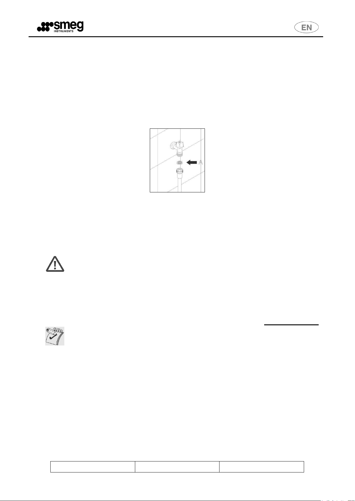
Water inlet filter A installed at the cock outlet must be periodically cleaned. First shut
off the supply cock, then unscrew the end of the water fill plug, remove the filter A and
clean it delicately under running water. Fit filter A back in its housing and carefully
retighten the water fill pipe.
fig. 7 – inlet filter "A"
How to clean the spray arms
The spray arms can be easily removed so that the nozzles can be periodically
cleaned to prevent clogging. Wash them under running water and then fit them back in
their housings. Make sure that their circular movement is not hindered in any way.
Page 36

Rev. 01
Man. WD1050
Pag. 36 - 40
How to clean the filter unit
The filtering unit consists of a circular filter with a filter cone, a micro filter and a
coarse filter. To ensure efficient operation of the machine it is extremely important to
keep the filters clean. They must be inspected frequently to remove deposits which
may adversely affect operation.
fig. 8 – Filter unit.
Coarse filter
To remove the coarse filter, press the tabs and pull upwards (see fig. 8 - panel 19).
Clean the filter and then reposition it.
Micro filter
This is located below the coarse filter (see panel 20). Check and clean whenever
inspecting the coarse filter.
For a perfect clean, use a brush and hot water.
Circular filter
To remove this filter:
press the tabs on the coarse filter and turn counterclockwise.
without pressing the tabs, raise the entire unit (i.e. filter, filter cone, coarse filter and
micro filter) (see panel 22).
When cleaning this filter it is worth also cleaning the others.
Page 37

Rev. 01
Man. WD1050
Pag. 37 - 40
Recommendations for correct maintenance
The filters should be cleaned under running water using a hard brush.
It is essential to clean the filters carefully according to the instructions given above:
the instrument washer will be unable to operate if the filters are clogged.
Fit the filters back in their housings with care, to prevent the washing pump from
being damaged.
9.2. IF THE INSTRUMENT WASHER IS NOT USED FOR A LONG PERIOD OF TIME
Follow the recommendations:
Carry out the soaking programme twice consecutively.
Remove the plug from the power socket.
Leave the door slightly open to prevent unpleasant odors from forming inside the
washing chamber.
Shut off the water cock.
9.3. REUSE OF THE INSTRUMENT WASHER AFTER A LONG PERIOD OF
INACTIVITY
Make sure that there are no rust or sludge deposits in the pipes. If this is the case,
allow water to run from the supply cock for a few minutes.
Plug the machine into the electricity main.
Re-connect the water supply hose and turn on the cock.
9.4. TROUBLESHOOTING
Slight faults can sometimes be eliminated by the user with the aid of the following
instructions.
1. If the programme fails to start, make sure that:
the instrument washer is connected to the electricity main;
the instrument washer is being powered;
the water cock is open;
the door of the instrument washer has been closed properly.
2. If water stagnates in the instrument washer, make sure that:
the drain plug is not bent;
the drain trap is not clogged;
the filters of the instrument washer are not clogged.
3. If the instruments are not cleaned properly, make sure that:
an adequate amount of detergent has been added;
there is regenerating salt in the relative reservoir;
the instruments have been positioned correctly;
the programme is suitable for the type and degree of dirt on the instruments;
all the filters are clean and correctly seated;
the holes in the water spray arms are not clogged;
Page 38

Rev. 01
Man. WD1050
Pag. 38 - 40
WARNING
Repairs to the appliance by unauthorized personnel are not covered by the warranty
and are at the user’s charge.
nothing is preventing the spray arms from turning.
4. If the instruments fail to dry or remain opaque, make sure that:
there is neutralizing agent in the relative container;
the neutralizing agent dispenser has been regulated in the correct way;
the detergent used is of good quality and has not lost its characteristics (e.g. owing
to incorrect storage, pack left open, etc.).
5. If the instruments are streaked, stained… make sure that:
the amount of neutralizing agent dispensed is not excessive.
6. If there are visible traces of rust in the washing chamber
The washing chamber is made of corrosion-proof steel, thus rust stains are due to
external factors (pieces of rust from the water pipes, etc.). Specific products are
available in the shops to eliminate these stains..
Make sure that the detergent dosage is correct. Some detergents can be more
corrosive than others.
Make sure that the salt reservoir plug is firmly closed and that the water softener
system has been correctly regulated.
Contact your nearest authorized technical assistance center if the faults persist
after compliance with the instructions given above.
Page 39

Rev. 01
Man. WD1050
Pag. 39 - 40
WARNING
In no case may SMEG be held liable for any direct or indirect damages deriving from
or in relation to inobservance of the above described checks.
10. ROUTINE CHECKS
10.1. DAYLY
a) control the detergent and neutralizing agent level: fill it up, if necessary.
b) check the sprinklers movement and their cleanliness.
10.2. WEEKLY
a) clean the sump filter.
b) perform Pr.4 without any load to clean and disinfect the washing chamber.
10.3. HALF YEARLY
c) check the status of the electrovalves filters: clean them if necessary, by making
hot water flow backwards;
d) check the tubes status.
10.4. YEARLY
At the end of the warranty period and over the successive years, call the nearest
Smeg authorized assistance centre in order to execute a complete check-up of the
machine.
Page 40

Rev. 01
Man. WD1050
Pag. 40 - 40
MACHINE DIMENSIONS [mm]
A
670 B 600 E 600 F 30
G
850
HYDRAULIC DISCHARGE
CONNECTIONS [mm]
H max
500
I (drain
height)
650 I 800
OPTIONAL DEMI TANK [mm]
L
1000 L 1200
DEMI TANK
The "demi water tank" is optional. Can be prepared if pressurized demineralized water is not
present in the plant (2bar <p_demi <5 bar). The tank must be properly positioned and used
with the accessory "PAD5".
Demineralized water helps to achieve a better washing.
IMPORTANT
If demineralized water isn't available: don't connect the demi pipe to the cold or
hot water, leave it disconnected and see the instructions (paragraph "DEMI
WATER SETTINGS" 6.12) in order to set correctly the demi water parameter.
11. WD1050 DIMENSIONS
Legenda
"cd" – condenser drain.
"d" – drain.
"cw" – cold water (tap water).
"dw" – demi water.
NOTE: the hydraulic connections can be arranged also on the left side of the machine, always taking into
account the maximum distance specified by the product, "H".
 Loading...