

Page 1
Rev. 08
User and maintenance manual
1
USER AND MAINTENANCE MANUAL
Page 2
Rev. 08
User and maintenance manual
2
Machine installation, maintenance, and repair operations must be performed
by authorized technical staff.
Repair operations performed by unauthorized staff, besides leading invalidating
the product warranty, can be source of danger for the user.
In case of replacement, an original spare part must be used.
If the device was not used in accordance to the instructions presented in this
manual, the product may no longer be covered by warranty and the safety of
this device could be compromised.
The producer declines all liability for any use that differs from what indicated in
the present manual.
The refrigerating unit has not to be used in presence of explosive gases or near
sources with high electronic or magnetic fields.
Smeg S.p.A. – Instruments Division
Via Leonardo da Vinci, 4
42016 Guastalla (RE)
www.smeg-instruments.com
READ CAREFULLY
This manual constitutes an integral part of the refrigerating unit.
It must be kept intact and at hand for the entire life cycle of the machine. It is necessary to read the
following manual carefully prior to using the device. Failure to read or thoroughly comprehend the
instructions in this manual may cause the device to malfunction and present hazards to the user.
The content of this manual is for information purposes only. The content and the equipment described
here may be subject to change without notification. The colours used in photographs of the product
(finishing panels), in diagrams and in screenshots are all purely guideline.
Page 3

Rev. 08
User and maintenance manual
3
SUMMARY
Products applicable to this manual ..................................................................................................... 5
Table of capacity and dimensions ...................................................................................................... 6
Table of technical specifications ......................................................................................................... 8
Standard and optional fitting ............................................................................................................. 10
1 STANDARDS AND GENERAL WARNINGS ........................................................................... 12
1.1 Certification .......................................................................................................................... 12
1.2 Initial reccomendations ........................................................................................................ 12
1.3 Aim, content and intended user of this manual..................................................................... 13
1.4 Product description .............................................................................................................. 13
1.5 General safety regulations ................................................................................................... 14
1.6 Customer responsibilities ..................................................................................................... 14
1.7 Customer service requests .................................................................................................. 14
1.8 Ordering of spare parts ........................................................................................................ 14
1.9 Aim and intended use of device ........................................................................................... 15
1.10 Unsuitable conditions for use ............................................................................................... 15
1.11 Materials and refrigerants .................................................................................................... 15
2 INSTALLATION ....................................................................................................................... 16
2.1 Trasportation and handling .................................................................................................. 16
2.2 Positioning ........................................................................................................................... 16
2.3 Wiring and electrical hook-up ............................................................................................... 17
2.4 Set-up operations ................................................................................................................ 18
2.5 Re-installation ...................................................................................................................... 18
2.6 Scrapping and disposal ........................................................................................................ 18
3 OPERATION ........................................................................................................................... 20
3.1 Safety and accident prevention ............................................................................................ 20
3.2 Safety dataplates and guards .............................................................................................. 20
3.3 Operating limits .................................................................................................................... 20
3.4 Environmental storage conditions ........................................................................................ 21
4 USER INSTRUCTIONS ........................................................................................................... 23
4.1 Appliance start-up ................................................................................................................ 23
4.2 Functions ............................................................................................................................. 23
4.3 Control panel ....................................................................................................................... 24
4.4 The menu tree ..................................................................................................................... 25
4.5 Alarm codes ......................................................................................................................... 27
4.6 Download procedure ............................................................................................................ 28
4.7 Procedure to disable the data logger ................................................................................... 29
4.8 Procedure to calibrate internal temperature probe S1 .......................................................... 30
4.9 Update of firmware release .................................................................................................. 30
4.10 GSM module ........................................................................................................................ 31
4.11 Dry contact for remote alarm ................................................................................................ 31
4.12 Back-up battery .................................................................................................................... 32
4.13 Temperature chart recorder ................................................................................................. 32
4.14 Shelf, drawer and installation ............................................................................................... 35
4.15 Divider for drawer and its installation ................................................................................... 36
5 ROUTINE MAINTENANCE ..................................................................................................... 37
5.1 Cleaning of the refrigerator .................................................................................................. 37
Page 4

Rev. 08
User and maintenance manual
4
5.2 Cleaning of the interior and exterior ..................................................................................... 37
5.3 Cleaning of the condenser ................................................................................................... 38
5.4 Precautions for prolonged disuse ......................................................................................... 39
6 SPECIAL MAINTENANCE AND REPAIRS ............................................................................. 40
7 TROUBLESHOOTING ............................................................................................................ 41
8 SYMBOLS USED .................................................................................................................... 43
9 ANNEXES ............................................................................................................................... 44
9.1 Technical Documentation .................................................................................................... 44
9.1.1 Electric diagram ............................................................................................................... 44
9.1.2 Safety test rerport ............................................................................................................. 44
10 AFTER-SALES SERVICE ....................................................................................................... 45
Page 5
Rev. 08
User and maintenance manual
5
Products applicable to this manual
The present manual is exclusively valid and applicable to the following SMEG product series.
Laboratory refrigerators, Pharmacy refrigerators
FV series
Adjustable temperature control range: lowest T = +2 °C, highest T = +15 °C
Factory pre-set: +4 °C
Models: FV10G1A, FV15G1A, FV20G1A, FV25G1A, FV30G1A, FV45G1A, FV52G1A, FV70G1A, FV140G2A,
FV10C1A, FV15C1A, FV20C1A, FV25C1A, FV30C1A, FV45C1A, FV52C1A, FV70C1A, FV140C2A, FV10G16A,
FV15G16A, FV20G16A, FV25G16A, FV30G16A, FV45G16A,
FV52G16A, FV70G16A, FV140G26A, FV10C16A, FV15C16A, FV20C16A, FV25C16A, FV30C16A, FV45C16A,
FV52C16A, FV70C16A, FV140C26A
Laboratory freezers
C series
Adjustable temperature control range: lowest T = -25 °C, -32 °C, -42 °C, highest T = -10 °C
Factory pre-set: -22 °C (C20), -30 °C (C30), -40 °C (C40)
Models: C20V10C1A, C30S16C1A, C30S22C1A, C30S25C1A, C30S32C1A, C40S60C1A, C25V70C1A,
C25V140C2A, C20V10C16A, C30S16C16A, C30S22C16A, C30S25C16A, C30S32C16A, C40S60C16A,
C25V70C16A, C25V140C26A
Combined refrigerators and freezers
DT series
Adjustable temperature control range: lowest T = +2 *C / -25 °C, highest T = +12 °C / -10 °C
Factory pre-set: +4 °C (refrigerator) / -25 °C (freezer)
Models: DT28CA, DT70CA, DT140CA, DT28GA, DT70GA, DT140GA, DT28C6A, DT70C6A, DT140C6A,
DT28G6A, DT70G6A, DT140G6A
Dual positive refrigerators
DTP series
Adjustable temperature control range: lowest T = +2 °C, highest T = +15 °C
Factory pre-set: +4 °C
Models: DTP30CA, DTP70CA, DTP140CA, DTP30GA, DTP70GA, DTP140GA, DTP30C6A, DTP70C6A,
DTP140C6A, DTP30G6A, DTP70G6A, DTP140G6A
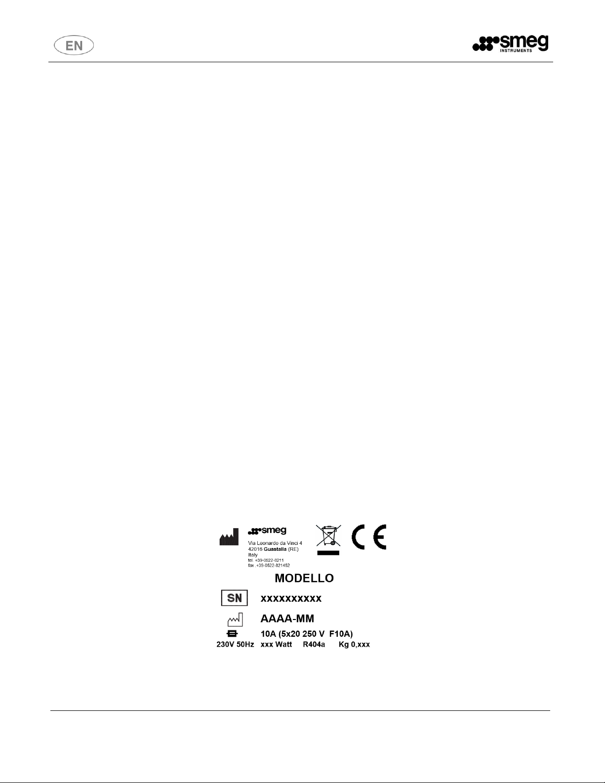
All relevant data referring to SMEG products can be found on the data label visible on the rear part of the
cabinet. Here is an example of the label:
Page 6
Rev. 08
User and maintenance manual
6
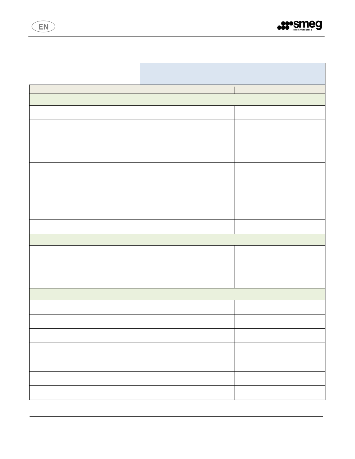
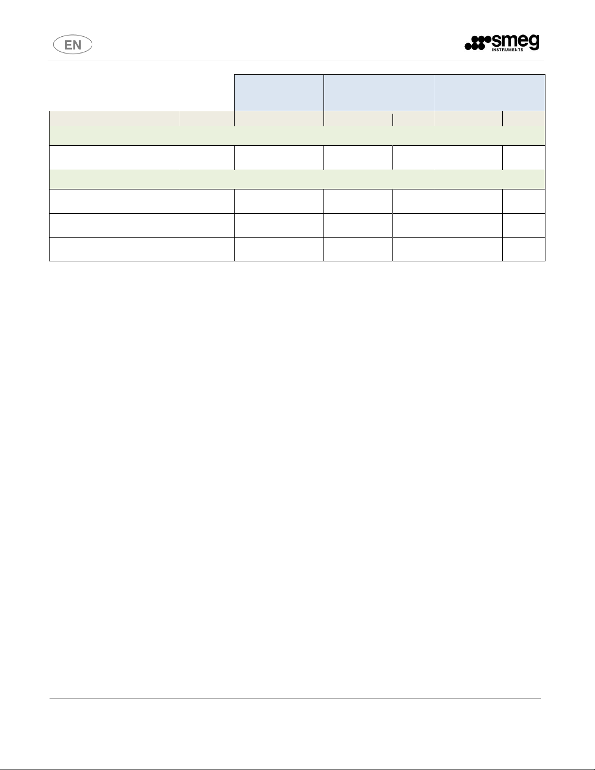
Internal
dimensions
External dimension and
unit net weigth
Dimensions of
packaging and shipping
weight
MODEL
Volume (L)
LxDxH (mm)
LxDxH (mm)
Kg
LxDxH (mm)
Kg
Laboratory refrigerators, Pharmacy refrigerators – FV series
FV10C1A - FV10G1A
FV10C16A - FV10G16A
100
480x465x460
600x600x860
73-76
680x680x1040
84-87
FV15C1A - FV15G1A
FV15C16A - FV15G16A
150
480x465x720
600x600x1360
76-80
680x680x1590
87-91
FV20C1A - FV20G1A
FV20C16A - FV20G16A
200
480x465x920
600x600x1560
85-91
680x680x1790
96-102
FV25C1A - FV25G1A
FV25C16A - FV25G16A
250
480x465x1120
600x600x1760
93-102
680x680x2050
106-115
FV30C1A - FV30G1A
FV30C16A - FV30G16A
300
480x465x1320
600x600x1960
104-113
680x680x2150
117-126
FV45C1A - FV45G1A
FV45C16A - FV45G16A
450
580x670x1200
700x800x1840
121-130
750x850x2150
136-145
FV52C1A - FV52G1A
FV52C16A - FV52G16A
520
580x670x1400
700x800x2040
129-138
750x850x2150
144-153
FV70C1A - FV70G1A
FV70C16A - FV70G16A
700
580x670x1500
700x800x1990
137-142
750x850x2150
152-167
FV140C2A - FV140G2A
FV140C26A - FV140G26A
1400
1280x670x1500
1400x800x1990
164-186
1500x850x2150
179-212
Combined refrigerators and freezers – DT series
DT28CA – DT28GA
DT28C6A – DT28G6A
180/100
TN 480x465x920
BT 480x465x460
600x600x1970
121-125
680x680x2150
134-138
DT70CA – DT70GA
DT70C6A – DT70G6A
350/350
TN 580x670x685
BT 580x670x685
700x800x2040
161-168
750x850x2150
174-181
DT140CA – DT140GA
DT140C6A – DT140G6A
700/700
TN 580x670x1500
BT 580x670x1500
1400x800x1990
195-217
1500x850x2150
221-243
Laboratory freezers – C series
C20V10C1A
C20V10C16A
100
480X465X460
600x600x860
81
680X680X1040
92
C30S16C1A
C30S16C16A
160
480x465x720
640x620x1400
85
680x680x1590
96
C30S22C1A
C30S22C16A
220
480x465x920
640x620x1600
94
680x680x1790
105
C30S25C1A
C30S25C16A
250
480x465x1120
640x620x1800
103
680x680x2050
116
C30S32C1A
C30S32C16A
320
480x465x1320
640x620x2000
115
680x680x2150
128
C40S60C1A
C30S32C16A
600
580x670x1400
780x840x1930
173
910x850x2100
186
C25V70C1A
C25V70C16A
700
580x670x1500
700x800x1990
144
750x850x2150
157
Table of capacity and dimensions
Page 7
Rev. 08
User and maintenance manual
7
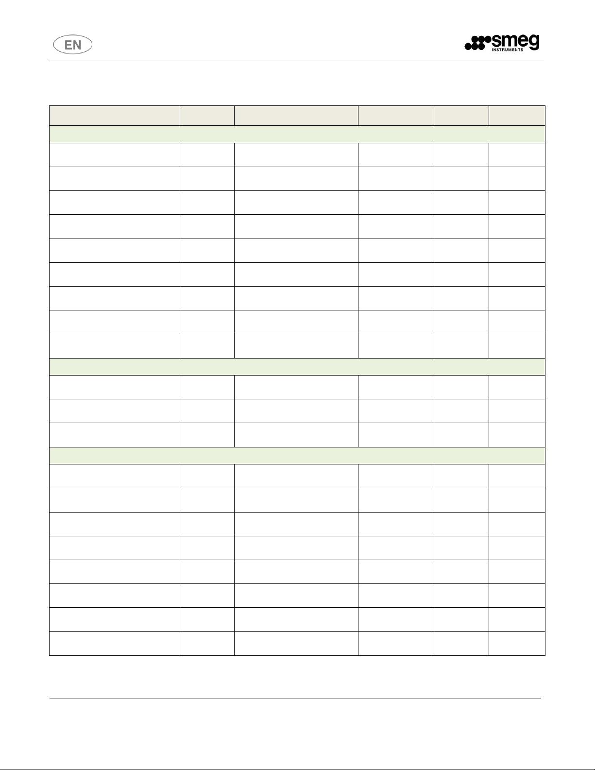
Internal
dimensions
External dimension and
unit net weigth
Dimensions of
packaging and shipping
weight
MODEL
Volume (L)
LxDxH (mm)
LxDxH (mm)
Kg
LxDxH (mm)
Kg
Laboratory refrigerators, Pharmacy refrigerators – FV series
C25V140C2A
C25V140C26A
1400
1280x670x1500
1400x800x1990
171
1500x850x2150
197
Dual positive refrigerators – DTP series
DTP30CA - DTP30GA
DTP30C6A - DTP30G6A
150/150
TN1 480x465x720
TN2 480x465x720
600x600x1960
125-131
680x680x2150
138-144
DTP70CA – DTP70GA
DTP70C6A – DTP70G6A
350/350
TN1 580x670x685
TN2 580x670x685
700x800x2040
161-168
750x850x2150
174-181
DTP140CA – DTP140GA
DTP140C6A – DTP140G6A
700/700
TN1 580x670x1500
TN2 580x670x1500
1400x800x1990
195-217
1500x850x2150
221-243
Legend:
TN = Reefrigerator compartment
BT = Freezer compartment
Page 8
Rev. 08
User and maintenance manual
8
MODEL
Volume (L)
Voltage (V) / Frequency (Hz)
Absorption (W)
Gas
Q.ty (Kg)
Laboratory refrigerators, Pharmacy refrigerators – FV series
FV10C1A - FV10G1A
FV10C16A - FV10G16A
100
230 / 50
230 / 60
245
245
R404a
0,130
FV15C1A - FV15G1A
FV15C16A - FV15G16A
150
230 / 50
230 / 60
245
245
R404a
0,150
FV20C1A - FV20G1A
FV20C16A - FV20G16A
200
230 / 50
230 / 60
245
245
R404a
0,180
FV25C1A - FV25G1A
FV25C16A - FV25G16A
250
230 / 50
230 / 60
360
360
R404a
0,200
FV30C1A - FV30G1A
FV30C16A - FV30G16A
300
230 / 50
230 / 60
360
360
R404a
0,250
FV45C1A - FV45G1A
FV45C16A - FV45G16A
450
230 / 50
230 / 60
336
370
R404a
0,250
FV52C1A - FV52G1A
FV52C16A - FV52G16A
520
230 / 50
230 / 60
336
370
R404a
0,250
FV70C1A - FV70G1A
FV70C16A - FV70G16A
700
230 / 50
230 / 60
260
320
R404a
0,250
FV140C2A - FV140G2A
FV140C26A - FV140G26A
1400
230 / 50
230 / 60
490
647
R404a
0,340
Combined refrigerators and freezers – DT series
DT28CA – DT28GA
DT28C6A – DT28G6A
180/100
230 / 50
230 / 60
427
708
R404a
0,150+0,130
DT70CA – DT70GA
DT70C6A – DT70G6A
350/350
230 / 50
230 / 60
350+480
295+450
R404a
0,200+0,200
DT140CA – DT140GA
DT140C6A – DT140G6A
700/700
230 / 50
230 / 60
1100
1100
R404a
0,340+0,340
Laboratory freezers – C series
C20V10C1A
C20V10C16A
100
230 / 50
230 / 60
345
345
R404a
0,130
C30S16C1A
C30S16C16A
160
230 / 50
230 / 60
450
450
R404a
0,200
C30S22C1A
C30S22C16A
220
230 / 50
230 / 60
450
450
R404a
0,200
C30S25C1A
C30S25C16A
250
230 / 50
230 / 60
450
450
R404a
0,230
C30S32C1A
C30S32C16A
320
230 / 50
230 / 60
450
450
R404a
0,230
C40S60C1A
C40S60C16A
600
230 / 50
230 / 60
580
580
R404a
0,550
C25V70C1A
C25V70C16A
700
230 / 50
230 / 60
530
588
R404a
0,290
C25V140C2A
C25V140C26A
1400
230 / 50
230 / 60
614
970
R404a
0,500
Table of technical specifications
Page 9
Rev. 08
User and maintenance manual
9
MODEL
Volume (L)
Voltage (V) / Frequency (Hz)
Absorption (W)
Gas
Q.ty (Kg)
Dual positive refrigerators – DTP series
DTP30CA - DTP30GA
DTP30C6A - DTP30G6A
150/150
230 / 50
230 / 60
245+245
245+245
R404a
0,150+0,150
DTP70CA – DTP70GA
DTP70C6A – DTP70G6A
350/350
230 / 50
230 / 60
350+350
295+295
R404a
0,200+0,200
DTP140CA – DTP140GA
DTP140C6A – DTP140G6A
700/700
230 / 50
230 / 60
260+260
320+320
R404a
0,340+0,340
Legend:
TN = Reefrigerator compartment
BT = Freezer compartment
Page 10
Rev. 08
User and maintenance manual
10
MODEL
Shelves
Drawers
Standard fitting
Optional accessories
Laboratory refrigerators, Pharmacy refrigerators – FV series
FV10C1A - FV10G1A
FV10C16A - FV10G16A
2
2*
Shelves
One way wheels
Schuko type plug
Control panel with alarm
system
Remote alarm
USB port
Data logger
Drawers
Kit of dividers for drawers
Wheels with frontal brakes
Chart recorder
Battery back up
SMS Alarms
LAN port
FV15C1A - FV15G1A
FV15C16A - FV15G16A
2
3*
FV20C1A - FV20G1A
FV20C16A - FV20G16A
3
4*
FV25C1A - FV25G1A
FV25C16A - FV25G16A
4
5*
FV30C1A - FV30G1A
FV30C16A - FV30G16A
5
6*
FV45C1A - FV45G1A
FV45C16A - FV45G16A
3
5*
FV52C1A - FV52G1A
FV52C16A - FV52G16A
4
6*
FV70C1A - FV70G1A
FV70C16A - FV70G16A
4
7*
FV140C2A - FV140G2A
FV140C26A - FV140G26A
4+4
14*
Combined refrigerators and freezers – DT series
DT28CA – DT28GA
DT28C6A – DT28G6A
3 (TN)
2 (BT)
Shelves/drawers (see previous
box)
One way wheels
Schuko type plug
Control panel with alarm
system
Remote alarm
USB port
Data logger
Shelves/drawers (see previous
box)
Kit of dividers for drawers
Wheels with frontal brakes
Chart recorder
Battery back up
SMS alarms
LAN port
DT70CA – DT70GA
DT70C6A – DT70G6A
2 (TN)
3 (BT)
DT140CA – DT140GA
DT140C6A – DT140G6A
4+4 (TN+BT)
4*+4* (TN+BT)
Laboratory freezers – C series
C20V10C1A
C20V10C16A
2
Shelves/drawers (see previous
box)
One way wheels
Schuko type plug
Control panel with alarm
system
Remote alarm
USB port
Data logger
Shelves/drawers (see previous
box)
Kit of dividers for drawers
Wheels with frontal brakes
Chart recorder
Battery back up
SMS alarms
LAN port
C30S16C1A
C30S16C16A
3
C30S22C1A
C30S22C16A
4
C30S25C1A
C30S25C16A
5
C30S32C1A
C30S32C16A
6
C40S60C1A
C40S60C16A
6
C25V70C1A
C25V70C16A
4
7*
C25V140C2A
C25V140C26A
8
7*+7*
Standard and optional fitting
Page 11
Rev. 08
User and maintenance manual
11
MODEL
Shelves
Drawers
Standard fitting
Optional accessories
Dual positive refrigerators – DTP series
DTP30CA - DTP30GA
DTP30C6A - DTP30G6A
2+2
3*+3*
Shelves
One way wheels
Schuko type plug
Control panel with alarm
system
Remote alarm
USB port
Data logger
Drawers
Kit of dividers for drawers
Wheels with frontal brakes
Chart recorder
Battery back up
SMS Alarms
LAN port
DTP70CA – DTP70GA
DTP70C6A – DTP70G6A
2+2
3*+3*
DTP140CA – DTP140GA
DTP140C6A – DTP140G6A
4+4
7*+7*
* Alternative configuration as optional
Page 12
Rev. 08
User and maintenance manual
12
Machine installation, maintenance, and repair operations must be performed by
authorized technical staff.
Repair operations performed by unauthorized staff, besides leading invalidating the
product warranty, can be source of danger for the user.
In case of replacement, an original spare part must be used.
If the device was not used in accordance to the instructions presented in this manual,
the product may no longer be covered by warranty and the safety of this device could
be compromised.
The producer declines all liability for any use that differs from what indicated in the
present manual.
The product warranty does not cover faulty parts due to negligence, inappropriate
use, or failure to comply with the instructions of the device operations; incorrect
installation or maintenance; repair and maintenance operations performed by
unauthorized staff or with non-original spare parts; transportation damages; and any
circumstance that cannot be ascribed to the device manufacturing defects.
Moreover, the warranty does not cover operations related to installation and
connection of alimentation and drain systems as well as maintenance operations
provided in the instruction booklet.
The installation of any accessory on the machine must be performed by authorized
technical staff.
To request further information about accessories: contact your trusted seller and/or
the authorized technical assistance, using the contact details provided in this manual.
1 STANDARDS AND GENERAL WARNINGS
1.1 Certification
All appliances are produced in accordance with European Community Regulations applicable at the
time of its appearance on the market. All appliances are manufactured in accordance with European
Directive 2014/35/UE, 2014/30/UE and following integrations and according to safety requirements for
electrical equipment for laboratory use (IEC 61010-1).
1.2 Initial reccomendations
READ THE PRESENT INSTRUCTION MANUAL CAREFULLY
This manual constitutes an integral part of the machine.
It must be kept intact and at hand for the entire life cycle of the machine.
It is necessary to read the following manual carefully prior to using the device.
Failure to read or thoroughly comprehend the instructions in this manual may cause the device to
malfunction and present hazards to the user.
The content of this manual is for information purposes only. The content and the equipment described
here may be subject to change without notification.
Page 13

Rev. 08
User and maintenance manual
13
1.3 Aim, content and intended user of this manual
This manual has been prepared with the objective to supply all instructions required for the correct use
of the appliance and to keep it in optimal condition. It also contains important user safety information.
The following professional roles are explained in order to define the responsibilities of each involved
parties.
Installer: a qualified technician, authorised by the manufacturer, who installs the appliance in
accordance with the instructions herein contained.
User: the person who, after having read this manual carefully, uses the appliance in accordance with
the intended specification of use described in this manual.
User’s responsibilities:
ensure that the product is kept at suitable temperatures without exceeding +38° of ambient
temperature;
be aware of the regulations governing the conservation of products to refrigerate and to observe
any whatsoever hygiene indications that may be applicable.
The user is obliged to read carefully the manual and refer to its information at all times. Particular
attention must be paid to the contents of heading 1.4 General safety warnings.
Routine maintenance technician: qualified operator able to perform routine maintenance of the
appliance by following the instructions in this manual (can be the customer too e).
Service engineer: qualified technician, authorised by the manufacturer to perform extraordinary
maintenance of the appliance.
Installer and service engineer must always be authorized by the manufacturer.
The manufacturer declines any whatsoever responsibility in case of improper use of the appliance
deviating from the reasonably construed intended use, and for all operations carried out that are not in
compliance with the instructions reported in the manual.
This manual must be stored in an accessible and known place for all operators (installer, user, routine
maintenance technician, service engineer).
1.4 Product description
The appliance comprises a single body with panelling in various materials and insulation in expanded
polyurethane foam density. The appliance instruments are located on the front panel where the
electrical wiring is housed. The motor unit and the condenser unit can be housed either on the top or
on the bottom closed by a frontal panel and a rear grid. The interior parts are fitted with suitable
supports for shelves, drawers and/or other accessories. The doors are fitted with an automatic return
device and magnetic seal elements. During the design and construction stage all measures have been
adopted to implement total safety including radius interior corners, funnel-shaped base panel to
convey condensate to exterior, no rough surfaces, fixed guards protecting moving or potentially
dangerous parts.
Page 14
Rev. 08
User and maintenance manual
14
This symbol on the equipment indicates a situation of danger. Pay attention and
read carefully what it refers to.
1.5 General safety regulations
Read this manual carefully and follow the prescriptions contained herein.
The user assumes full responsibility in case of operations carried out without observing the
instructions in the manual. None of SMEG products are designed to work in presence of flammable
gases or solvent that may easily burn, hence keep off the unit of any of these situations.
Primary general safety regulations:
do not touch the unit with wet hands and/or feet
do not use the appliance with bare feet
do not insert screwdrivers or other pointed objects between guards or moving parts of the
appliance
do not pull the power cord to disconnect the appliance from the electrical mains
make sure that the appliance is not used by unsuitably qualified persons
before performing any cleaning or maintenance on the appliance disconnect it from the electrical
mains by switching off the main switch and extracting the plug
in case of faults or malfunctions, switch off the appliance and do not attempt to repair it by
yourself. All service and repair operations must be performed exclusively by a suitable
authorized engineer.
1.6 Customer responsibilities
The customer is required to:
execute the electrical connection of the appliance
prepare the place of installation
provide consumable materials for cleaning
perform routine maintenance
In the case of power failures or malfunctions do not open the doors in order to maintain as much as
possible the internal temperature. If the problem persists for more than few hours, move the contents
to a more suitable place.
1.7 Customer service requests
For all technical problems and any requests for technical service, refer exclusively to your local dealer,
pointing out model and serial number.
1.8 Ordering of spare parts
Orders of spare parts should be made by consulting the part reference code and the serial number of
your appliance. Consult your dealer.
Page 15

Rev. 08
User and maintenance manual
15
The user must consult the dealer or the manufacturer, as the case of SMEG
appliances require original spare parts, failing of which product certification
decades.
Products must be stored in order to ensure efficient air circulation inside the
appliance and shall not come out of the shelf perimeter.
All uses except authorized used of the appliance shall be construed as “improper
use” for which the manufacturer declines all responsibility..
1.9 Aim and intended use of device
The appliance is conceived for the use in hospitals, laboratories, pharmacies and industries and it is
intended solely for the preservation of laboratories and medical products, which request various
controls and warning in case of sudden alteration of temperature.
In particular: medicinal products; laboratory samples; thermo-sensitive chemical reactants
It is absolutely not intended for storage of flammable materials, gas or explosive materials
1.10 Unsuitable conditions for use
The appliance must not be used exposed to bad weather, with adapters, multiple sockets or extension
leads, in an explosive atmosphere or in an atmosphere with a fire risk or closed to heating sources.
In case of built-in refrigerators a proper ventilation of compressor must be provided.
1.11 Materials and refrigerants
Materials in contact or potentially in contact with products are in compliance with the relevant
directives. The appliance is designed and built so that contact parts can be cleaned before each use.
The refrigerants utilized comply with established regulations.
In case of accidental leakage of gas, there is no danger of flammability.
Contact service.
Page 16

Rev. 08
User and maintenance manual
16
The appliance must be transported and handled exclusively in upright position, in
observance of the instructions printed on the packing.
Use gloves when handling wooden packing materials and the wooden base to
protect the hands from splinters.
2 INSTALLATION
2.1 Trasportation and handling
This precaution is necessary to avoid contamination of the refrigerant circuit with compressor lube oil
with resulting valve and heat exchanger coil failure and problems starting the electric motor.
The manufacturer cannot be considered responsible for any problems due to transport executed in
conditions other than those specified herewith.
The appliance is secured to a wooden base by means of a screw and wrapped in a cartoon box.
The appliance must be handled using a folk lift truck or a pallet truck with suitable forks (fork length at
least equal to 2/3 length of unit). The dimensions and weight of the packed appliance are shown in
technical tables (see tables at the beginning of manual).
2.2 Positioning
Incorrect positioning can cause damage to the appliance and generate hazardous conditions for
personnel. The installer must therefore observe the following general regulations:
make sure you maintain a minimum of 10 cm from the walls and the ceiling
the room must be well ventilated
keep well away from sources of heat
avoid direct sunlight
remove packing material
remove accessories from inside the unit
wood basement removal: by means of a hammer until the feet-block hinder ledge, tilt the cabinet
to one side and loosen the two thread-forming screws, drag the cabinet from the back side
holding the basement still until the four feet have gone out from the containing holes, slightly tilt
the cabinet backward and take the basement away pulling it from the front side
position the appliance with the help of a spirit level. Adjust the levelling feed on the metal base of
the unit if necessary.
remove the protective PVC film from the external surfaces of the unit
position the shelf runners in the holes in the uprights
insert the shelves in the runners
insert the condensate collection tray, if needed, in the relevant runners located beneath the unit
Page 17

Rev. 08
User and maintenance manual
17
It is important to connect the appliance correctly to an efficient earth system
executed in compliance with the relevant legislation.
2.3 Wiring and electrical hook-up
The electrical plant and electrical hook-up operations must be performed by a qualified electrician.
For safety reasons adhere to the following indications:
check that the electrical plant is suitably sized for the absorbed power of the unit
if the electrical socket and the plug on the appliance power cord are incompatible, charge the
plug with a suitable component, ensuring the replacement part is of the approved type
insert the cable into the jack (Fig. 1)
do not use reductions or multi-way adapters (Fig. 2)
the appliance must be positioned so that plug can be easily reached (Fig. 2)
Fig. 1 Fig. 2
The refrigerators are equipped with double protection fuses 10A (CEI EN 61010-1, Classification 66-
5). The freezers model C25V70C1A-C25V140C2A and C40S60C16A are equipped with double
protection fuses 15A (CEI EN 61010-1, Classification 66-5) (Fig. 3-4).
Fig. 3 Fig. 4
Page 18

Rev. 08
User and maintenance manual
18
2.4 Set-up operations
To avoid errors and accidents, perform a series of checks for possible damage sustained during
transport, installation and hook-up operations before starting up the unit.
PRELIMINARY CHECKS
check the condition of the power cord (no cut or chaffing)
check that the feed, door hinges and shelf support are stable
check the door seals and drawers are not damaged (broken or scratched) and that the door closes
and is sealed properly
make sure pipelines, unions are in perfect condition
INDICATIONS FOR OPTIMAL DUTY
do not block the motor compartment air vents
do not lay objects on the top of the appliance
before storing products wait until they are cold
arrange the products on suitable shelves or in containers. Do not place products directly on the
base or against the walls, doors or fixed guards of the unit
make sure doors are kept closed
keep the defrost water drain outlet clear
limit the frequency and duration of opening; each time the door is opened the internal temperature
will alter
load products at ambient temperature gradually to allow correct refrigeration
perform routine maintenance regularly (see Chapter 5)
2.5 Re-installation
Observe the following procedure:
switch off the appliance from the main switch
disconnect the power cord from the electrical outlet
handle the appliance in accordance with the instruction heading 2.1
follow the instructions in heading 2.2 for positioning and hook-ups in the new location
2.6 Scrapping and disposal
SMEG appliances may contain materials, which at the end of the working life of the apparatus, must
be disposed at one of the recycling centres nominated by your Local National Health Department or as
specified by the law in force. Scrapping and disposal of the appliance must be carried out in full
observance of established legislation in your country.
In particular, the apparatus may contain the following materials:
- Iron
- Copper
- Aluminium
- Non-biodegradable plastics
- Fibre glass for printed circuits
- Ferrite
- Batteries
Page 19

Rev. 08
User and maintenance manual
19
In line with European Directive 2012/19/UE for waste electrical and electronic
equipment (WEEE), this electrical product must not be disposed of as unsorted
municipal waste. Please dispose of this product by returning it to your local municipal
collection point for recycling.
Before you dispose, verify that the appliance has been sanitized in accordance with
internal procedures.
- CFC-free refrigeration gas
- Electrical and electronic equipment (WEEE)
SMEG shall not be chargeable for any disposal of the apparatus at the end of its working life.
The term of the useful life of refrigerator/freezer is 10 years. After this period, the device must be
checked and possibly re-conditioned only by the manufacturer
Page 20

Rev. 08
User and maintenance manual
20
3 OPERATION
3.1 Safety and accident prevention
SMEG refrigerators are designed to include several features to ensure the safety and the
protection for the Operators and for the material stored in the cabinets.
The following list describes the protections adopted against mechanical risks:
stability: the appliance is designed and built so that even with the shelves fully extracted in the
intended conditions of operation may remain stable, so that it can be used without risk of tipping,
falling or sudden movement.
surfaces, edges, corners: accessible parts of the appliance have no sharp corners, sharp
edges or rough surface that could cause injuries.
moving parts: moving parts of the unit are designed, built and configured to avoid risks. Moving
parts are protected by fixed guards to prevent accidental contact that could result in injury.
Measures adopted for protection against additional risks:
electrical power: the appliance is designed, built and fitted out with the aim of preventing the
risk of electric shock in compliance with established safety legislation
noise: the appliance is designed and built to reduce risks related to the emission of airborne
noise to the minimum level (below 60 dB)
3.2 Safety dataplates and guards
It is strictly forbidden:
to tamper or remove the evaporator cover that protects the user from the risk of cutting on the
heat exchanger fins;
to remove the data plate fixed to the inside edge of the motor housing showing technical
specification and earth connection warning;
to remove the data plates on the evaporator unit cover near the electrical wiring inside the motor
housing which warn the user to disconnect electrical power before working on appliance;
to remove the data tag fixed to the power cord showing the type of power supply.
The manufacturer declines all responsibility for safety of the appliance if the above recommendations
are not observed.
3.3 Operating limits
The appliance is designed and built to work with ambient temperatures between +10 °C and +38 °C. It
is also destined and tested for tropical countries. If the ambient conditions are different it will not be
possible to achieve the top performance levels specified by the manufacturer.
Power supply can be one of the following, according to country of destination:
230 V - 50Hz
230 V - 60Hz
Page 21

Rev. 08
User and maintenance manual
21
3.4 Environmental storage conditions
The appliance when not in use must be stored indoors at a temperature not exceeding +40 °C and
below 0 °C.
Page 22

Rev. 08
User and maintenance manual
22
Page 23

Rev. 08
User and maintenance manual
23
4 USER INSTRUCTIONS
4.1 Appliance start-up
Before switching on the unit, check that the electrical connections have been made correctly and
above all, that the ground connection is available and working properly (Sect. 2.2.). Perform
preliminary cleaning of the unit as described in Section 5.1.
SWITCH ON THE UNIT
To start the appliance, it is necessary to press button ON on the display. The main screen will be
displayed and message « SMEG » will appear.
Then you will be requested to enter the user password.
USER PASSWORD = 555
TURN OFF THE APPLIANCE
Press the button OFF on the display, you will be asked to enter the user password. If password is
correct, after entering the last digit, the appliance switches off.
4.2 Functions
ANTIPANIC FUNCTION
In all menu screens, after 120 seconds from pressing the key button, the controller returns to the main
menu, without saving any unconfirmed changes.
LCD FUNCTION – ENERGY SAVING
One minute after pressing any key, the backlight of the screen switches off automatically (stand-by
status). Lighting will be switched on again by pressing any key.
DATALOGGER
When the appliance is on, alarms and data of probes are recorded. Each single record is related to
date and time. It’s possible to record a maximum of 46000 entries (which corresponds to about one
month recording). Then you have to download records on a USB pen drive (a specific alarm will
advise you when memory is full).
In case you don’t want to download records, press ALARM key and then MUTE key. The alarm
message will disappear and the controller will overwrite on previous registrations.
Page 24

Rev. 08
User and maintenance manual
24
Compressors
Clean
Battery
H. Temp.
L. Temp.
DL6
USB connector for
data loading/unloading
4.0 °C
Data
MENU
SET
LIGHT
4.0
Frig. mod. xxxx
4.3 Control panel
According to the model, all units are equipped with the same control panel (CPU control board) but
with different settings depending on their configuration.
LED DECODING – STATE OF ALARM
LED DL6 on – general alarm
LED DL2 on – condenser dirty/blocked or unsuitable environment
LED DL3 on – power failure or damaged battery
LED DL4 on – high temperature alarm
LED DL5 on – low temperature alarm
KEYS DECODING
F1 – set point key, temperature setting + arrow ↑
F2 – display of alarms memory + arrow ↓
F3 – light key + arrow
F4 – menù / ESC
F1 – TEMPERATURE SETTING
By pressing key F1 (SET), set point is shown on the display. By pressing any of the arrow-keys ↑↓, a
message “enter password XXX” appears. If password inserted is correct, pre-set data appears to be
modified. By using arrow-keys ↑↓, the requested value can be set, press “ENTER” to confirm. New
data is recorded and main screen/menu is displayed again.
F3 - LIGHT
Press key F3 to turn manually on/off light (not present in freezer models)
F4 - MENU
Press F4 to enter menu list
Page 25

Rev. 08
User and maintenance manual
25
4.4 The menu tree
1. Alarms
2. Info
3. Display
4. Password
Scroll with arrow ↓ and ↑ to select the menu, then confirm with ENTER.
Parameters are displayed. In order to modify any pre-set parameters, you always need to enter menu
by selecting 4.PASSWORD and by entering the user password 555. In this way you access the
modifiable menu that is completed by two additional items, that are:
0.User parameters
5.Updatesoftware
Scroll with ↓ and ↑ to choose and select the parameter you need to modify and confirm with “enter”,
then the value of parameter blinks, always with ↓ and ↑ you modify the parameter, press “enter” to
confirm and the value returns fixed.
In any part of menu/at any time of setting if you push key ESC you go back to the main menu.
1. ALARMS
List of latest 20 recorded alarms with data, time and type of alarm.
The maximum voltage that can be applied to the relay contacts is 230V AC.
2. INFO (the following data can’t be modified)
- Manual defrost
- Serial number
- Delay door Alarm = delay open door alarm (how many minutes before alarm starts)
- High temp. alarm = delta T value (difference with set point temperature) and delay (how many
minutes before alarm starts)
- Low temp. alarm = delta T value (difference with set point temperature) and delay (how many
minutes before alarm starts)
- Defrost = time between defrosting cycles
- Time defrost = maximum time of defrosting cycle
Page 26

Rev. 08
User and maintenance manual
26
3- Display
= English
= °C
=
4-Password
4-1= User
4-2=Help
4-3= Factory
4- 2 Help
x - -
- Defrosting type = fan/heater/gas
- Evap. temperature = evaporator temperature that is value detected by probe
- Cond. temperature = condenser temperature that is value detected by probe
- Tot.h. = total number of working hours
- Firmware rel. = xxxxx firmware release
- Fuse = fuse type
- Gas type = type of gas used
- Gas kg = gas quantity
- Data logger
Scroll with ↑ and ↑ to see all data. Once displayed last data or selecting key “esc”, display shows main
menu again.
3. DISPLAY
The mainboard can be set in the following languages:
: ITALIAN – ENGLISH – FRENCH – POLISH – SPANISH
To change the language press key “MENU” and by using arrow-keys select 4.PASSWORD, confirm
with “ENTER”, select 4-1 USER, enter 555 and confirm with ENTER; Select 3-DISPLAY and confirm
with ENTER, by means of arrow-keys select the requested language. Confirm by pressing “ENTER”,
then select “ESC”, the display shows main menu again.
: °C-°F
: to adjust display brightness
: to set up date and time (selecting YES on option of daytime, the controller updates
automatically data on standard daytime; selecting NO, no change is made)
4. PASSWORD
Password levels:
4-1 / User : end user
4-2 / Help : technician
4-3 / Factory : factory setting
Enter password. If password is correct, parameters’ changes are enabled (according to password
level). If password entered is not correct, message “wrong password” will appear on display for five
seconds and then it will automatically go back to previous menu.
To modify password data, enter standard user password 555, then select key “PASSWORD” and
Page 27

Rev. 08
User and maintenance manual
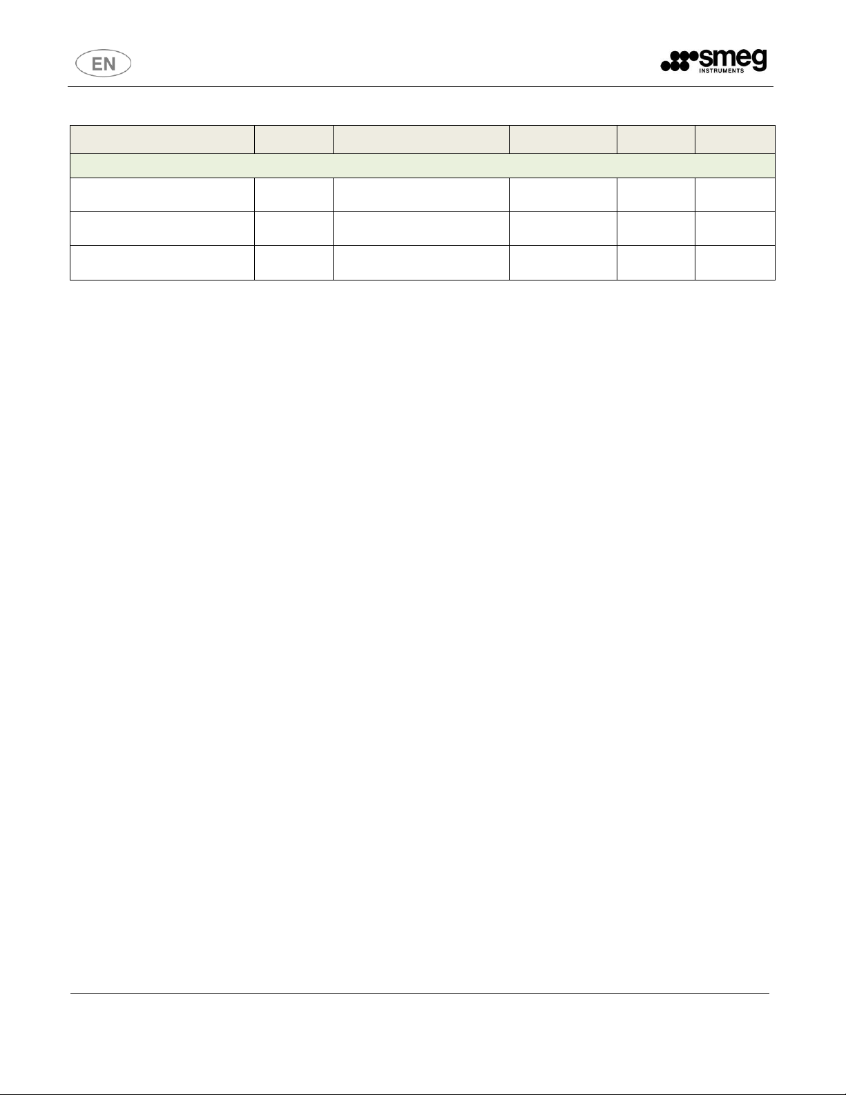
27
#
Alarm on Display
Alarm description
1
AL00
Power Failure = when power is restored, a message is shown indicating
length of time of power failure
2
AL01
Faulty Temperature Probe (S1 probe damaged; it can be reset)
BT (negative temperatures) = compressor works continuosly
TN (positive temperatures) = compressor works according to pre-set ON
and OFF times.
3
AL02
Damaged probe of Evaporator temperature
4
AL03
High Temperature (=defrost alarm)
5
AL04
Low Temperature (=freezing alarm)
6
AL05
Blocked/dirty condenser (= condenser high temperature alarm) - please
see section 5 – ordinary maintenance
7
AL06
Damaged probe of Condenser temperature (= probe S3 damaged)
8
DOOR
Open door alarm
9
AL70
No battery = battery is low; check is made automatically every 10 hours.
10
AL71
No power (= power failure)
13
Full Memory
Full memory – download records
14
Clock
Damaged clock
15
AM1
General alarm - Condenser cleaning
16
AM2
General alarm – check/maintenance on appliance is required
17
AM3
Security
confirm it; as a consequence the message “CHANGE PASSWORD” will show. Enter new password
and confirm it.
In case you forget your modified password, take power off and then give power again, keeping both
keys F1 and F2 pressed at the same time. Display shows the message “PASSWORD” blinking, then,
it becomes fixed. At this point appliance switches on automatically, you can enter the menu by
standard user password.
4.5 Alarm codes
Temperature alarms are activated with a delay.
Error Parameters = wrong parameters entered
Full Memory = download records. When the appliance is on, alarms and data of probes are recorded.
Each single record is related to date and time. It is possible to record a maximum of 46000 entries
(which corresponds to about one month recording). Then you have to download records on a USB pen
Page 28

Rev. 08
User and maintenance manual
28
5,5 °C
Date
Download records
Download data
Data load
drive (a specific alarm will advise you when memory is full).
In case you don’t want to download records, press ALARM key and then MUTE key. The alarm
message will disappear and the controller will overwrite on previous registrations.
When alarm starts, Led DL6 and buzzer are on, the symbol of triangle is blinking, indicating the code
and type of alarm. Above mentioned alarm is recorded in memory of alarm. In order to visualize it,
press key F2 (it will be shown as “AL”).
Press key MUTE and buzzer is silenced.
When alarm is restored, buzzer is disabled, Led DL6 is off, AL symbol and triangle symbol disappear.
When alarm issue is solved, press key MUTE.
When alarms AL03 and AL04 are no more present, press key Mute, a message “DOWNLOAD
RECORDS” appears and you can download records by using USB pen. When procedure is finished,
alarm is reset automatically.
In case GSM Module and back-up battery are connected, alarm message is forwarded automatically
to memorized mobile numbers. When alarm is no more present, a notification message of “standard”
working will be forwarded.
WARNING!!!
Some alarms require a manual reset because the alarm remains visible on display even if the
has been muted. Press any keys to turn on the display; then press the key below warning sign
(in this case third key from left below the display) and MUTE key to clear it. In this way, the
alarm is deleted from the display but remains recorded in the memory of alarms.
WARNING!!! Appliances without back-up battery
In case of power failure, when power returns, alarm AL00 (power failure) appears on display,
indicating that the unit has been without power and showing the time when power failed. To
clear the alarm from display, press any keys so that the display is on and then select keys the
key below warning sign (in this case third key from left below the display) and MUTE key to
clear it. In this way the alarm is removed from display but remains recorded in memory of
alarms.
Appliances with automatic defrosting show “DEF” on display during execution of defrosting.
4.6 Download procedure
Insert the USB key into the hole, the symbol « » appears on the display
with related messages:
1 - Download records (= working temperature and alarms recording)
2 - Download data (= parameters setting)
3 - Data load (= enter new parameters)
(F1-F2-F3 corresponds to « arrows » - as indicated in the picture)
1 – Download records - To download memory records, press key «ENTER» and confirm it, the
Page 29

Rev. 08
User and maintenance manual
29
message «DOWNLOAD RECORDS » is flashing to indicate operation in progress.
Once procedure is finished, the message « DOWNLOAD RECORDS» will be replaced by message
«OFF KEY». By removing the USB pen, the display shows the main menu screen.
In order to read the file in a correct way on your PC, please open it by using the Note Pad
program.
At the end of download record procedure, a file is generated containing information according to the
following format:
M;23-05-12;09:53;4,00;26,5;
Or, in case of freezer with evaporator temperature S2
M;23-05-12;09:53;-20,0;-27,0;26,5;
M = OPERATING STATE (M=normal, A=alarm, S=switching-off, R=switching-on)
29-05-2012 = DATE
09:53 = HOUR
4,00 (or -20,0) = INTERNAL TEMPERATURE
-27,0 = EVAPORATOR TEMPERATURE (ONLY FOR FREEZER WITH S2 PROBE)
26,5 = CONDENSER TEMPERATURE (ONLY IF THE PROBE IS PRESENT)
In case an alarm is recorded, the file will appear as follows:
A;29-05-12;09:53;5
A = ALARM
29-05-2012 = DATE
09:53 = HOUR
5 = ALARM TYPE
To identify type of alarm, please refer to section 4.5
2 – Download data (parameters for service) - If you want to download parameters, that is the
setting of the refrigerator, press ENTER on Download; you will be requested to digit the Password.
Once the password is entered the data will be downloaded. When you read “FINISHED” on display,
please remove the USB pen and the display will automatically return to the initial screen.
3 – Data load – If parameters need to be modified or updated, please insert USB pen and by
pressing «data load», the appliance will be automatically programmed with new data.
4.7 Procedure to disable the data logger
- Press any key to activate the display
- Press MENU key
- By using the arrow keys go to point 4-PASSWORD+ENTER
- Select USER PASSWORD. By means of arrow keys enter password 555 (5+ENTER, 5+ENTER
5+ENTER)
- In this way you enter the MENU
- Scroll up to point 0-USER PARAMETERS+ENTER
- Then scroll up to point 3-RECORDINGS+ENTER
- By means of arrow keys change YES to NO and press ENTER to confirm
- Exit programming by means of ESC key to return to initial display screen
Page 30

Rev. 08
User and maintenance manual
30
4.8 Procedure to calibrate internal temperature probe S1
- Press any key to activate the display
- Press MENU key
- By using the arrow keys go to point 4-PASSWORD+ENTER
- Select USER PASSWORD. By means of arrow keys enter password 555 (5+ENTER, 5+ENTER,
5+ENTER)
- In this way you enter the MENU
- Scroll up to point 0-USER PARAMETERS+ENTER
- Then scroll up to point 5-CALIBR.PROBES1+ENTER
- At this point insert the new value and press ENTER to confirm
- Exit programming by means of ESC key to return to initial display screen
Example on how to choose the new parameter to enter: if the temperature showing on display is +4
°C, while inside the appliance with a different instrument +6 °C is registered, the value to be entered
for calibration of probe will be +2 °C.
4.9 Update of firmware release
Check the release number on display.
A. Press MENU
B. Scroll up to INFO(2)+ENTER
C. Scroll up to REL.FIRMWARE=(NUMBER)
A – TYPE OF PROCEDURE TO UPDATE FIRMWARE NR 0.32 OR PREVIOUS ONES
If firmware installed on your appliance is n.032 or previous to this one, please perform the following
procedure:
A. Copy updated firmware on USB pen (DON’T OPEN THE FILE IN YOUR PC)
B. Switch off the appliance by pressing “OFF” key and by typing password (USER= 555)
C. Take power off (unplug)
D. Press at the same time the three keys from left below the display and plug again by keeping the
keys pressed.
E. As soon as display will show various writing, stop pressing the three keys.
F. Insert the USB pen in the port hole
G. When the word “OFF” will show, take off the USB pen and switch on the appliance again.
H. In some cases the word “PARAMETER ALARM” can show (depending on firmware release). In
order to reset the alarm, press the key “ALL” (third from left side below display)+MUTE key.
Repeat the operation until the alarm disappears.
At this point, double check that new Firmware release number has been installed.
B – TYPE OF PROCEDURE TO UPDATE FIRMWARE NR 0.35 TO CURRENT RELEASE
If firmware installed on your appliance is n.035 or following to this one, please perform the following
procedure:
A. Copy updated firmware on USB pen (DON’T OPEN THE FILE ON YOUR PC)
B. Switch off the appliance by pressing “OFF” key and by typing password (USER= 555)
Page 31

Rev. 08
User and maintenance manual
31
GSM is connected
Field intensity – blinking symbol indicates that no field is present
Symbol flashing in case of wrong PIN entering - exit configuration/set-up, switch off the
appliance and enter PIN number (after three wrong entries, the system is blocked)
Symbol blinking - it means that SIM hasn’t been inserted
General Error - substitute GSM module
C. Press the MENU key and scroll up to PASSWORD(4)+ ENTER
D. Type password (USER= 555)
E. Go to main menu and scroll up to “UPDATE SOFTWARE” (point n.5 for user)+ENTER
F. By means of arrows choose “YES” and confirm with ENTER.
G. Follow instructions showing on display
H. At this point various writing will show. Insert USB pen in the port hole
I. When the word “OFF” will show, take off the USB pen and switch on the appliance again.
J. In some cases the word “PARAMETER ALARM” can show (depending on FW release). In order to
reset the alarm, press the key “ALL” (third from left side below display)+MUTE key. Repeat the
operation until the alarm disappears.
At this point, double check that new Firmware release number has been installed.
4.10 GSM module
When an alarm is activated, a message is forwarded to pre-set mobile phone numbers automatically,
with:
Name, Serial Number, Alarms codes and description of alarm type.
Moreover, in case appliance includes back-up battery, if power supply is failing, a message is
forwarded to selected numbers indicating above mentioned information and “ON BATTERY”. When
situation has been restored, a message will follow indicating “POWER OK”.
By sending a SMS with the word “STATUS” to GSM number, installed into the appliance, you can
make an inquiry on its status. You will receive either a reply message with “NO ALARMS” and value of
recorded temperature, in case no alarms are present, or the alarms codes detected.
Symbols on display when GSM is connected are:
IMPORTANT: To use GSM module (if included in the appliance), document will be sent
containing password and instructions for GSM module use and loading/recording of mobile
phone numbers.
4.11 Dry contact for remote alarm
The refrigerator communicates its own state also by means of a dry contact placed in the rear upper
side. With remote alarm relay you can signal an alarm condition with a remote-alarm device on your
Page 32

Rev. 08
User and maintenance manual
32
site. The connection for remote alarm is a clean switch contact. The contact exchanges under all
alarm conditions.
Note: connections have to be made as indicated below, and above all should be tested with
equipment in operation.
The pin assignment of the connection port is as follows:
4.12 Back-up battery
The battery back-up (optional accessory) allows to monitor the temperature of the appliance and any
faults and alarms in case of power failure. It is an optional accessory.
4.13 Temperature chart recorder
The control panel is arranged to be equipped with one or two chart recorders (in fridge-freezers units).
It is an optional accessory. Temperature is recorded on a weekly chart diagram.
The appliance is equipped with: diagram discs, battery, pen.
In order to make the pen start operating on chart recorder paper:
1. Open the cover with the key
2. With one hand slightly lift the pen arm, with the other hand remove the protection of the pen
3. Lower the pen
4. Close the cover with key
Fig. 6
Page 33

Rev. 08
User and maintenance manual
33
HOW TO REPLACE THE CHART
1. Open the cover with the key (Fig. 6)
2. Push the spring of the chart holder sideways and lift it (Fig. 7 – Fig. 8)
3. Remove the chart (Fig. 9 – Fig. 10)
4. Insert the new chart
5. Lower the spring of the diagram holder and push it sideways
Fig. 7 Fig. 8
HOW TO REPLACE THE FIBRE TIPPED PEN
The fibre tipped pin is a consumable, which has an average duration of about one year.
1. Open the cover with the key (Fig. 6)
2. With one hand slightly lift the pen arm, with the other hand pull out the pen (Fig. 9)
3. Place the new pen, gently pushing it on to the pen arm and remove the protection of the pen
4. Close the cover with key
Fig. 9 Fig. 10
Page 34

Rev. 08
User and maintenance manual
34
HOW TO INSTALL A NEW BATTERY
1. Open the cover with the key (Fig. 6)
2. Lift up the pen (Fig. 9)
3. Lift up the chart disc (Fig. 10)
4. Remove the alkaline battery 1,5 V LR03 and put another new one, taking care of polarity (Fig. 11)
5. Lower the pen
6. Close the cover with key
Fig. 11
PEN ARM CALIBRATION
We suggest to check recorder's calibration every 6 months. If there is a difference greater than +/- 2%
between the digital display and chart recorder, proceed as follows:
1. Take gently the arm (B) of the pen.
2. With a small screwdriver calibrate the regulation screw (A) until the fiber pen comes to the correct
temperature.
Fig. 12
Page 35

Rev. 08
User and maintenance manual
35
Beware, do not open all drawers at the same time.
4.14 Shelf, drawer and installation
All appliances are fitted with shelves and/or drawers according to the scheme at pag.8. Both the shelf
and the drawer have a maximum capacity of 20kg/each.
Some models can be equipped with stainless steel drawers as optional accessories in the maximum
quantities indicated in the scheme at page 8. In the event that drawer is purchased at a later time, the
user can proceed to the assembly and fit it following the steps outlined below in the photos. The same
procedure must be performed in case of need to remove the drawer for cleaning.
.
Fig. 13 Fig. 14
Fig. 15 Fig. 16
Page 36

Rev. 08
User and maintenance manual
36
Fig. 17 Fig. 18
4.15 Divider for drawer and its installation
Drawers can be equipped with plexiglas dividers (optional accessory) that allow the creation of
longitudinal compartments inside the drawer. In case you bought the kit of dividers for drawer, you can
proceed with its installation following the steps outlined below in the photos. The same procedure has
to be followed in case of need to remove the partitions for thorough cleaning.
Fig. 19 Fig. 20
Page 37

Rev. 08
User and maintenance manual
37
5 ROUTINE MAINTENANCE
Basic safety regulations
We summarise the elementary safety regulations to ensure that the user or maintenance technician
can perform the work in conditions of total safety:
do not touch the unit with wet hands and/or feet;
do not use the appliance with bare feet;
do not insert screwdrivers or other pointed objects between guards or moving parts of the
appliance;
do not pull the power cord to disconnect the appliance from the electrical mains;
before performing any cleaning or maintenance on the appliance disconnect it from the electrical
mains by switching off the main switch and extracting the plug
Prohibited: removal of guards and safety devices
It is strictly forbidden to remove guards or safety devices when performing routine maintenance work.
The manufacturer disclaims all liability that may arise if this regulation is not observed.
Emergency measures in case of fire
- Disconnect the unit from the electrical power socket.
- Do not use water to extinguish the fire.
- Use powder or foam extinguishers.
5.1 Cleaning of the refrigerator
The unit is designed to preserve medical/laboratory products so it is important to keep it clean for
reasons of hygiene and health. The appliance is thoroughly cleaned in our factory before delivery. We
recommend, however, that you clean the interior of the appliance before use. Before cleaning the
appliance make sure the power cord is disconnected.
5.2 Cleaning of the interior and exterior
To this end, we indicate cleaning products to be used for exterior and interior of the appliance:
Water and neutral detergent only and not abrasive. Do not use solvent or thinners.
Cleaning methods: use soft clean cloth with suitable products for both external and internal
surfaces.
Disinfection: Avoid substances that can alter the organoleptic characteristics of products.
Rinsing: use a cloth or sponge soaked with fresh clean water. Do not use water jets.
Frequency: once a week or at different intervals in accordance with the type of product stored.
Page 38

Rev. 08
User and maintenance manual
38
During this operation use the following personal safety measures:
- safety glasses
- respiratory protection mask
- gloves
5.3 Cleaning of the condenser
The condenser is a heat exchanger hence if it is dirty or clogged the air cannot pass freely into the
same, it cannot do its job properly and the efficiency of the refrigeration system falls down
proportionally. FOR THOSE REASONS IT IS IMPORTANT TO KEEP CLEAN THE CONDENSER
WHERE TYPICALLY IT MEANS TO CLEAN IT MONTHLY.
WARNING!!!
Always switch off the unit and disconnect power cord before cleaning, it is dangerous to do it
with power: fan may start suddenly at any time!
According to the model, compressor can be placed on top or at the bottom of the appliance.
Compressor on top
Use a convenient ladder to reach the condenser. Use an air jet or an aspirator with a soft dry brush if
necessary (Fig. 21) and remove any dust or fluff from the heat exchanger fins.
After cleaning, start the appliance.
Fig. 21
Page 39

Rev. 08
User and maintenance manual
39
Compressor on the bottom
To access the condenser at base, unscrew the 2 screws by means of a screwdriver (fig. 22), then pull
with both hands the panel at the front bottom of the appliance (fig. 23):
Fig. 22 Fig. 23
After removal, use an air jet or an aspirator with a soft dry brush if necessary and remove any dust
(Fig. 24) or fluff from the heat exchanger fins.
5.4 Precautions for prolonged disuse
If the refrigerator should remain unused for more than 15 days please proceed as follows:
switch off the appliance and disconnect the power cord
clean the interior of the cabinet, shelves, trays, runners and supports, paying special attention to
critical areas such as articulations and magnetic sealing strips
leave doors slightly open to prevent accumulation of residual humidity
Fig. 24
Page 40

Rev. 08
User and maintenance manual
40
6 SPECIAL MAINTENANCE AND REPAIRS
All maintenance work not described in the previous sections must be considered “Special
Maintenance”.
Special maintenance interventions and repairs are to be performed exclusively by specialised
technicians authorised by the manufacturer.
The manufacturer declines all liability in the case of work performed by the user or
unauthorised persons, or if non-original spare parts are fitted to the appliance.
Page 41

Rev. 08
User and maintenance manual
41
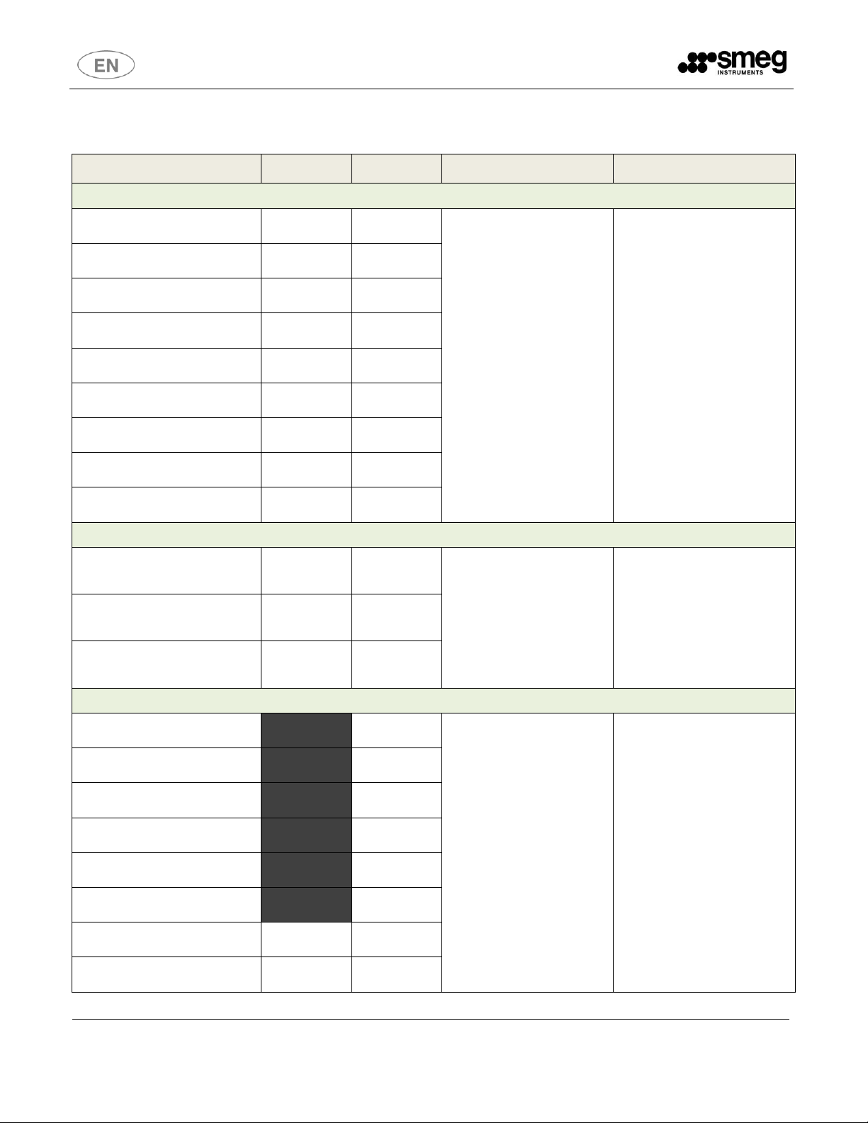
Fault
Possible Cause
Action
The appliance does not switch
on
ON-OFF Switch (located on the
rear side) is on OFF
Power failure
Other
Press ON
Check the plug, socket, fuses,
electrical line
Contact service department
Refrigeration unit does not start
Set temperature has already
been reached
Defrosting cycle in progress
(DEF on display)
Control panel fault
Other
Set new temperature
Wait for the end of defrost cycle,
switch off and then on again after
few minutes
Contact service department
Contact service department
Refrigeration unit runs
constantly but does not reach
set temperature
Room temperature too high
Condenser dirty
Refrigerant needs recharging
Fan of condenser does not work
Door gasket is damaged
Evaporator is coated with ice
Defrost valve is open
Provide for better ventilation of
the room and clean condenser
Clean condenser
Contact service department
Contact service department
Check seals /make sure
refrigerator contents are not
obstructing the door
Defrost manually
Contact service department
7 TROUBLESHOOTING
Here below a list of possible faults that might occur with descriptions of possible causes and a short
corresponding actions list to try:
Page 42

Rev. 08
User and maintenance manual
42
Fault
Possible Cause
Action
Water or ice deposits in the drip
tray
Drain outlet is clogged
Appliance not levelled
Clean drain and drain outlet
See heading 2.2
Page 43

Rev. 08
User and maintenance manual
43
Remove the tension before removing
the protection
Warning symbol
Earth symbol
It is necessary to consult the Instruction
Booklet before carrying out the
operation
Clean condenser regularly
8 SYMBOLS USED
Page 44

Rev. 08
User and maintenance manual
44
9 ANNEXES
The following documentation is enclosed:
9.1 Technical Documentation
9.1.1 Electric diagram
9.1.2 Safety test rerport
Page 45

Rev. 08
User and maintenance manual
45
10 AFTER-SALES SERVICE
Our After-Sales Department will be able to provide you with guidance about keeping your device
functioning correctly and put you in touch with your nearest authorised Service Centre.
Italy only
After Sales Service (Assistance and Technical Information) contact:
o National number 0522.184.85.95
o Fax 02.38073401
o Email: assistenza.instruments@smeg.it
For further information
o Email: instruments@smeg.it
International Customers
Please contact your Local Smeg Distributor or write an email to:
After Sales Service (Assistance and Technical Information) contact:
o Email: service.instruments@smeg.it
For further information
o Email: instruments@smeg.it
Page 46

Rev. 08
User and maintenance manual
46
SMEG S.p.A.
Instruments Division
Via Leonardo da Vinci, 4 – 42016 Guastalla (RE) Italy
www.smeg-instruments.com
 Loading...