

Page 1

Page 2

L
IMITED
Limited Warranty Statement: SMC Networks, Inc. (“SMC”) warrants its products to be
free from defects in workmanship and materials, under normal use and service, for the
applicable warranty term. All SMC products carry a standard 90-day limited warranty from
the date of purchase from SMC or its Authorized Reseller. SMC may, at its own discretion,
repair or replace any product not operating as warranted with a similar or functionally
equivalent product, during the applicable warranty term. SMC will endeavor to repair or
replace any product returned under warranty within 30 days of receipt of the product.
The standard limited warranty can be upgraded to a Limited Lifetime* warranty by registering
new products within 30 days of purchase from SMC or its Authorized Reseller. Registration
can be accomplished via the enclosed product registration card or online via the SMC web
site. Failure to register will not affect the standard limited warranty. The Limited Lifetime
warranty covers a product during the Life of that Product, which is defined as the period of
time during which the product is an “Active” SMC product. A product is considered to be
“Active” while it is listed on the current SMC price list. As new technologies emerge, older
technologies become obsolete and SMC will, at its discretion, replace an older product in its
product line with one that incorporates these newer technologies. At that point, the obsolete
product is discontinued and is no longer an “Active” SMC product. A list of discontinued
products with their respective dates of discontinuance can be found at:
http://www.smc.com/index.cfm?action=customer_service_warranty.
All products that are replaced become the property of SMC. Replacement products may be
either new or reconditioned. Any replaced or repaired product carries either a 30-day limited
warranty or the remainder of the initial warranty, whichever is longer. SMC is not responsible
for any custom software or firmware, configuration information, or memory data of
Customer contained in, stored on, or integrated with any products returned to SMC pursuant
to any warranty. Products returned to SMC should have any customer-installed accessory or
add-on components, such as expansion modules, removed prior to returning the product for
replacement. SMC is not responsible for these items if they are returned with the product.
Customers must contact SMC for a Return Material Authorization number prior to returning
any product to SMC. Proof of purchase may be required. Any product returned to SMC
without a valid Return Material Authorization (RMA) number clearly marked on the outside
of the package will be returned to customer at customer’s expense. For warranty claims within
North America, please call our toll-free customer support number at (800) 762-4968.
Customers are responsible for all shipping charges from their facility to SMC. SMC is
responsible for return shipping charges from SMC to customer.
W
ARRANTY
i
Page 3

L
IMITED WARRANTY
WARRANTIES EXCLUSIVE: IF AN SMC PRODUCT DOES NOT OPERATE AS
WARRANTED ABOVE, CUSTOMER’S SOLE REMEDY SHALL BE REPAIR OR
REPLACEMENT OF THE PRODUCT IN QUESTION, AT SMC’S OPTION. THE
FOREGOING WARRANTIES AND REMEDIES ARE EXCLUSIVE AND ARE IN
LIEU OF ALL OTHER WARRANTIES OR CONDITIONS, EXPRESS OR IMPLIED,
EITHER IN FACT OR BY OPERATION OF LAW, STATUTORY OR OTHERWISE,
INCLUDING WARRANTIES OR CONDITIONS OF MERCHANTABILITY AND
FITNESS FOR A PARTICULAR PURPOSE. SMC NEITHER ASSUMES NOR
AUTHORIZES ANY OTHER PERSON TO ASSUME FOR IT ANY OTHER
LIABILITY IN CONNECTION WITH THE SALE, INSTALLATION,
MAINTENANCE OR USE OF ITS PRODUCTS. SMC SHALL NOT BE LIABLE
UNDER THIS WARRANTY IF ITS TESTING AND EXAMINATION DISCLOSE THE
ALLEGED DEFECT IN THE PRODUCT DOES NOT EXIST OR WAS CAUSED BY
CUSTOMER’S OR ANY THIRD PERSON’S MISUSE, NEGLECT, IMPROPER
INSTALLATION OR TESTING, UNAUTHORIZED ATTEMPTS TO REPAIR, OR
ANY OTHER CAUSE BEYOND THE RANGE OF THE INTENDED USE, OR BY
ACCIDENT, FIRE, LIGHTNING, OR OTHER HAZARD.
LIMITATION OF LIABILITY: IN NO EVENT, WHETHER BASED IN CONTRACT
OR TORT (INCLUDING NEGLIGENCE), SHALL SMC BE LIABLE FOR
INCIDENTAL, CONSEQUENTIAL, INDIRECT, SPECIAL, OR PUNITIVE
DAMAGES OF ANY KIND, OR FOR LOSS OF REVENUE, LOSS OF BUSINESS, OR
OTHER FINANCIAL LOSS ARISING OUT OF OR IN CONNECTION WITH THE
SALE, INSTALLATION, MAINTENANCE, USE, PERFORMANCE, FAILURE, OR
INTERRUPTION OF ITS PRODUCTS, EVEN IF SMC OR ITS AUTHORIZED
RESELLER HAS BEEN ADVISED OF THE POSSIBILITY OF SUCH DAMAGES.
SOME STATES DO NOT ALLOW THE EXCLUSION OF IMPLIED WARRANTIES
OR THE LIMITATION OF INCIDENTAL OR CONSEQUENTIAL DAMAGES FOR
CONSUMER PRODUCTS, SO THE ABOVE LIMITATIONS AND EXCLUSIONS
MAY NOT APPLY TO YOU. THIS WARRANTY GIVES YOU SPECIFIC LEGAL
RIGHTS, WHICH MAY VARY FROM STATE TO STATE. NOTHING IN THIS
WARRANTY SHALL BE TAKEN TO AFFECT YOUR STATUTORY RIGHTS.
* SMC will provide warranty service for one year following discontinuance from the active
SMC price list. Under the limited lifetime warranty, internal and external power supplies, fans,
and cables are covered by a standard one-year warranty from date of purchase.
SMC Networks, Inc.
38 Tesla
Irvine, CA 92618
Warranty terms may differ according to geographic region. For complete details please
consult your country's support section of the SMC web site, http://www.smc.com
ii
Page 4

C
OMPLIANCES
Federal Communication Commission Interference
Statement
This equipment has been tested and found to comply with the limits for a Class B digital
device, pursuant to Part 15 of the FCC Rules. These limits are designed to provide reasonable
protection against harmful interference in a residential installation. This equipment generates,
uses and can radiate radio frequency energy and, if not installed and used in accordance with
the instructions, may cause harmful interference to radio communications. However, there is
no guarantee that interference will not occur in a particular installation. If this equipment
does cause harmful interference to radio or television reception, which can be determined by
turning the equipment off and on, the user is encouraged to try to correct the interference by
one or more of the following measures:
• Reorient or relocate the receiving antenna.
• Increase the distance between the equipment and receiver.
• Connect the equipment into an outlet on a circuit different from that to which the receiver
is connected.
• Consult the dealer or an experienced radio/TV technician for help.
This device complies with Part 15 of the FCC Rules. Operation is subject to the following
two conditions: (1) This device may not cause harmful interference, and (2) this device must
accept any interference received, including interference that may cause undesired operation.
FCC Caution: Any changes or modifications not expressly approved by the party
responsible for compliance could void the user's authority to operate this equipment.
FCC Radiation Exposure Statement:
This equipment complies with FCC radiation exposure limits set forth for an uncontrolled
environment. This equipment should be installed and operated with a minimum distance of
20 cm between the radiator and your body.
This transmitter must not be co-located or operating in conjunction with any other antenna
or transmitter.
IMPORTANT NOTE:
IEEE 802.11b or 802.11g operation of this product in the U.S.A. is firmware-limited to
channels 1 through 11.
iii
Page 5

C
OMPLIANCES
Industry Canada Statement
Operation is subject to the following two conditions:
1. this device may not cause interference and
2. this device must accept any interference, including interference that may cause undesired
operation of the device
To prevent radio interference to the licensed service, this device is intended to be operated
indoors and away from windows to provide maximum shielding. Equipment (or its transmit
antenna) that is installed outdoors is subject to licensing.
This device has been designed to operate with an antenna having a maximum gain of 1.5 dBi.
Any antenna having a higher gain is strictly prohibited per regulations of Industry Canada.
The required antenna impedance is 50 ohms.
To reduce potential radio interference to other users, the antenna type and its gain should be
so chosen that the EIRP is not more than required for successful communication.
To prevent radio interference to the licensed service, this device is intended to be operated
indoors and away from windows to provide maximum shielding. Equipment (or its transmit
antenna) that is installed outdoors is subject to licensing.
EC Declaration of Conformity
SMC contact for these products in Europe is:
SMC Networks Europe,
Edificio Conata II,
Calle Fructuos Gelabert 6-8, 2o, 4a,
08970 - Sant Joan Despi,
Barcelona, Spain.
Marking by the above symbol indicates compliance with the Essential Requirements of the
R&TTE Directive of the European Union (1999/5/EC). This equipment meets the
following conformance standards:
EN 300 328-1 December 2001 V1.3.1
EN 300 328-2 December 2001 V1.2.1
EN 301 489-1 September 2001 V1.4.1
EN 301 489-17 September 2000 V1.2.1
EN 60950 January 2000
iv
Page 6

C
OMPLIANCES
Countries of Operation & Conditions of Use in the
European Community
This device is intended to be operated in all countries of the European Community.
Requirements for indoor vs. outdoor operation, license requirements and allowed channels of
operation apply in some countries as described below:
Note: The user must use the configuration utility provided with this product to ensure the
channels of operation are in conformance with the spectrum usage rules for European
Community countries as described below.
• This device requires that the user or installer properly enter the current country of
operation in the command line interface as described in the user guide, before operating
this device.
• This device will automatically limit the allowable channels determined by the current
country of operation. Incorrectly entering the country of operation may result in illegal
operation and may cause harmful interference to other system. The user is obligated to
ensure the device is operating according to the channel limitations, indoor/outdoor
restrictions and license requirements for each European Community country as described
in this document.
• This device may be operated indoors or outdoors in all countries of the European Community
using the 2.4 GHz band: Channels 1 - 13.
Declaration of Conformity in Languages of the
European Community
English Hereby, SMC Networks, declares that this Radio LAN device is in
compliance with the essential requirements and other relevant provisions
of Directive 1999/5/EC.
Finnish Valmistaja SMC Networks vakuuttaa täten että Radio LAN device
tyyppinen laite on direktiivin 1999/5/EY oleellisten vaatimusten ja sitä
koskevien direktiivin muiden ehtojen mukainen.
Dutch Hierbij verklaart SMC Networks dat het toestel Radio LAN device in
overeenstemming is met de essentiële eisen en de andere relevante
bepalingen van richtlijn 1999/5/EG
Bij deze SMC Networks dat deze Radio LAN device voldoet aan de
essentiële eisen en aan de overige relevante bepalingen van Richtlijn
1999/5/EC.
French Par la présente SMC Networks déclare que l'appareil Radio LAN device est
conforme aux exigences essentielles et aux autres dispositions pertinentes
de la directive 1999/5/CE
v
Page 7
C
OMPLIANCES
Swedish Härmed intygar SMC Networks att denna Radio LAN device står I
Danish Undertegnede SMC Networks erklærer herved, at følgende udstyr Radio
German Hiermit erklärt SMC Networks, dass sich dieser/diese/dieses Radio LAN
Greek
överensstämmelse med de väsentliga egenskapskrav och övriga relevanta
bestämmelser som framgår av direktiv 1999/5/EG.
LAN device overholder de væsentlige krav og øvrige relevante krav i
direktiv 1999/5/EF
device in Übereinstimmung mit den grundlegenden Anforderungen und
den anderen relevanten Vorschriften der Richtlinie 1999/5/EG befindet".
(BMWi)
Hiermit erklärt SMC Networks die Übereinstimmung des Gerätes Radio
LAN device mit den grundlegenden Anforderungen und den anderen
relevanten Festlegungen der Richtlinie 1999/5/EG. (Wien)
vi
Italian Con la presente SMC Networks dichiara che questo Radio LAN device è
conforme ai requisiti essenziali ed alle altre disposizioni pertinenti stabilite
dalla direttiva 1999/5/CE.
Spanish Por medio de la presente SMC Networks declara que el Radio LAN device
cumple con los requisitos esenciales y cualesquiera otras disposiciones
aplicables o exigibles de la Directiva 1999/5/CE
Portuguese SMC Networks declara que este Radio LAN device está conforme com os
requisitos essenciais e outras disposições da Directiva 1999/5/CE.
Page 8

C
OMPLIANCES
Safety Compliance
Underwriters Laboratories Compliance Statement
Important! Before making connections, make sure you have the correct cord set. Check it
(read the label on the cable) against the following:
Operating Voltage Cord Set Specifications
120 Volts UL Listed/CSA Certified Cord Set
Minimum 18 AWG
Type SVT or SJT three conductor cord
Maximum length of 15 feet
Parallel blade, grounding type attachment plug rated
15 A, 125 V
240 Volts (Europe only) Cord Set with H05VV-F cord having three conductors
The unit automatically matches the connected input voltage. Therefore, no additional
adjustments are necessary when connecting it to any input voltage within the range marked
on the power adapter.
with minimum diameter of 0.75 mm2
IEC-320 receptacle
Male plug rated 10 A, 250 V
Information for Power Source
This unit is to be used with a class 2 or level 3 external power adapter, approved suitable for
use in North American equipment installation, having an output voltage rating of 9 V DC,
and output current rating of 1.0 A or equivalent. The external AC adapter must be complied
with the requirements of LPS (Limited Power Sources).
N11846
vii
Page 9

C
OMPLIANCES
Wichtige Sicherheitshinweise (Germany)
1. Bitte lesen Sie diese Hinweise sorgfältig durch.
2. Heben Sie diese Anleitung für den späteren Gebrauch auf.
3. Vor jedem Reinigen ist das Gerät vom Stromnetz zu trennen. Verwenden Sie keine Flüssigoder Aerosolreiniger. Am besten eignet sich ein angefeuchtetes Tuch zur Reinigung.
4. Die Netzanschlu ßsteckdose soll nahe dem Gerät angebracht und leicht zugänglich sein.
5. Das Gerät ist vor Feuchtigkeit zu schützen.
6. Bei der Aufstellung des Gerätes ist auf sicheren Stand zu achten. Ein Kippen oder
Fallen könnte Beschädigungen hervorrufen.
7. Die Belüftungsöffnungen dienen der Luftzirkulation, die das Gerät vor Überhitzung
schützt. Sorgen Sie dafür, daß diese Öffnungen nicht abgedeckt werden.
8. Beachten Sie beim Anschluß an das Stromnetz die Anschlußwerte.
9. Verlegen Sie die Netzanschlußleitung so, daß niemand darüber fallen kann. Es sollte
auch nichts auf der Leitung abgestellt werden.
10. Alle Hinweise und Warnungen, die sich am Gerät befinden, sind zu beachten.
11. Wird das Gerät über einen längeren Zeitraum nicht benutzt, sollten Sie es vom Stromnetz trennen. Somit wird im Falle einer Überspannung eine Beschädigung vermieden.
12. Durch die Lüftungsöffnungen dürfen niemals Gegenstände oder Flüssigkeiten in das
Gerät gelangen. Dies könnte einen Brand bzw. elektrischen Schlag auslösen.
13. Öffnen sie niemals das Gerät. Das Gerät darf aus Gründen der elektrischen Sicherheit
nur von authorisiertem Servicepersonal geöffnet werden.
14. Wenn folgende Situationen auftreten ist das Gerät vom Stromnetz zu trennen und von
einer qualifizierten Servicestelle zu überprüfen:
a. Netzkabel oder Netzstecker sind beschädigt.
b. Flüssigkeit ist in das Gerät eingedrungen.
c. Das Gerät war Feuchtigkeit ausgesetzt.
d. Wenn das Gerät nicht der Bedienungsanleitung entsprechend funktioniert oder Sie mit
Hilfe dieser Anleitung keine Verbesserung erzielen.
e. Das Gerät ist gefallen und/oder das Gehäuse ist beschädigt.
f. Wenn das Gerät deutliche Anzeichen eines Defektes aufweist.
15. Stellen Sie sicher, daß die Stromversorgung dieses Gerätes nach der EN 60950 geprüft
ist. Ausgangswerte der Stromversorgung sollten die Werte von AC 7,5-8 V, 50-60 Hz
nicht über oder unterschreiten sowie den minimalen Strom von 1 A nicht unterschreiten.
Der arbeitsplatzbezogene Schalldruckpegel nach DIN 45 635 Teil 1000 beträgt 70 dB(A)
oder weniger.
viii
Page 10

MPEG-4 (Wireless) Pan/Tilt
Internet Camera
User’s Guide
Version 1.0
Page 11

TABLE OF CONTENTS
A B O U T T H I S GU I D E ...........................................................3
1. INTRODUCTION ..............................................................4
F
EATURES AND BENEFITS .........................................................5
U
NPACKING THE PACKAGE .......................................................7
S
YSTEM REQUIREMENT.............................................................8
P
HYSICAL DESCRIPTION............................................................9
2. HARDWARE INSTALLATION.................................12
A
TTACHING THE METAL CLIP
C
ONNECTING THE ETHERNET CABLE ......................................13
A
TTACHING THE POWER SUPPLY ............................................13
3 . S E C U R I TY .........................................................................14
4 . A P P L I C AT I O N O F T H E C A M E R A.......................15
A
PPLICATION DIAGRAMS OF THE CAMERA.......................................16
5 . U S I N G T HE C A M E R A .................................................19
W
EB CONFIGURATION UTILITY...............................................19
C
ONTROLLING AND VIEWING VIDEO ......................................22
B
ASIC SETUP ...........................................................................24
A
DVANCED SETUP...................................................................29
M
AINTENANCE ........................................................................47
L
OGOUT...................................................................................52
H
ELP........................................................................................53
..................................................12
1
Page 12

6 . F F D S H OW & AV I S A V I O R......................................................54
I
NSTALLING FFDSHOW............................................................54
C
ONFIGURATION OF FFDSHOW ...............................................58
P
LAYING THE VIDEO ...............................................................59
F
IXING THE VIDEO FILE...........................................................60
7 . I P V I E W PR O ....................................................................62
I
NSTALLATION.........................................................................62
G
ETTING STARTED ..................................................................66
U
SING IPVIEW PRO .................................................................69
C
ONFIGURING THE SYSTEM.....................................................74
8 . A P P E N D IX.........................................................................88
FREQUENTLY ASKED QUESTIONS.......................................88
A.
B.
PING YOUR IP ADDRESS....................................................91
C.
TROUBLE SHOOTING...........................................................92
D.
TIME ZONE TABLE..............................................................96
E.
ADJUST INTERNET CAMERA FOCUS....................................98
F.
SPECIFICATION ....................................................................99
G.
GLOSSARY OF TERMS .......................................................101
2
Page 13

ABOUT THIS GUIDE
This manual provides instructions and illustrations on how to use
your MPEG-4 (Wireless) Pan/Tilt Internet Camera, includes:
z Chapter 1, Introduction, provides the general information
on the camera.
z Chapter 2, Hardware Installation, describes the hardware
installation procedure for the camera.
z Chapter 3, Security, explains the security feature of the
camera.
z Chapter 4, Application of the Camera, provides the
illustrations of the camera’s applications.
z Chapter 5, Using the Camera, guides you through the
configuration using the web browser.
z Chapter 6, FFdshow & AVISavior, helps you to use the
utilities provided within the Installation CD.
z Chapter 7, IPView Pro, helps you to install and use the
software.
z Chapter 8, Appendix.
Please note that the illustrations or setting values in this manual
are FOR YOUR REFERENCE ONLY. The actual settings and
values depend on your system and network. If you are not sure
about the respective information, please ask your network
administrator or MIS staff for help.
3
Page 14

1
INTRODUCTION
Thank you for purchasing the MPEG-4 (Wireless) Pan/Tilt
Internet Camera, a standalone system that can be connected
directly to an Ethernet or Fast Ethernet, and also supported by the
wireless transmission based on the IEEE 802.11g standard*.
With support for latest MPEG-4 technology, you can record
streaming video that utilizes high quality MPEG-4 images to your
hard drive, enable motion detection and setup automated email
alerts for security. The built-in microphone provides you with the
audio function, allowing you to “watch” and “listen” from the
camera. Compared to the conventional PC Camera, the camera
features a built-in CPU and web-based solutions that can provide
a cost-effective solution to transmit the real-time high-quality
video images and sounds synchronously for monitoring.
The camera can be managed remotely, so that you can use a web
browser to access and control it from any notebook/desktop PC
over the Intranet or Internet. The simple installation procedures
and web-based interface allow you to integrate it into your
network easily. With comprehensive applications supported, the
Internet camera is your best solution for remote monitor, high
quality, and high performance video images.
* For wireless model.
4
Page 15

Features and Benefits
Simple to Use
The MPEG-4 (Wireless) Pan/Tilt Internet Camera is a standalone
system with built-in CPU, no special hardware (such as a PC
frame capture card) or software required. The camera supports
DirectX 9.0; therefore, the only requirement you need is the web
browser software such as Internet Explorer 5.0 or above. Once
you have a valid IP Address, just connect it and you can view the
picture and receive sound from your camera. In addition, the
camera’s stand allows you to adjust the camera for optimal
viewing angle. You can tilt the camera right or left (up to 170/
170 degrees), forward or backward (up to 45/90 degrees).
Support Variety of Platforms
The camera supports TCP/IP networking, SMTP e-mail, HTTP
and other Internet related protocols. It can be utilized in a mixed
operating system environment, including Windows 98SE/ME/
2000/XP. Moreover, it can be integrated easily into other www/
Intranet applications.
Web Configuration
Applying a standard web browser, the administrator can configure
and manage the camera directly from its own web page via the
Intranet or Internet. Up to 64 users name and password are
permitted with privilege setting controlled by the administrator.
5
Page 16

Remote Utility
The powerful IPView Pro application assigns the administrator
with a pre-defined user ID and password, allowing the
administrator to modify the camera settings from the remote site
via Intranet or Internet. When new firmware is available, you can
also upgrade remotely over the network for added convenience.
Users are also allowed to monitor the image, and take snapshots.
Broad Range of Applications
With today’s high-speed Internet services, the camera can provide
the ideal solution for live video images over the Intranet or
Internet for remote monitoring. The camera allows remote access
from a web browser for live image viewing, and allows the
administrator to manage and control the camera anywhere and
anytime in the world. Apply the camera to monitor various
objects and places such as homes, offices, banks, hospitals, childcare centers, amusement parks and other varieties of industrial
and public monitoring. The camera can also be used for intruder
detection; in addition, it can capture still images for archiving and
many more applications.
6
Page 17

Unpacking the Package
Unpack the package and check all the items carefully. In addition
to this User’s Guide, be certain that you have:
One MPEG-4 (Wireless) Pan/Tilt Internet Camera
One External Antenna (for wireless model)
One power adapter
One RJ-45 Ethernet Cable
One Metal Clip
One Installation CD-ROM
One Quick Installation Guide
If any item contained is damaged or missing, please contact your
local dealer immediately. Also, keep the box and packing
materials in case you need to ship the unit in the future.
7
Page 18

System Requirement
Networking
Local Area Network:
10Base-T Ethernet or 100Base-TX Fast Ethernet
Wireless Local Area Network (wireless model):
IEEE 802.11g Wireless LAN
Accessing the Camera
For Web Browser Users
Operating System: Microsoft® Windows® 98SE/ME/
2000/XP
CPU: Intel Celeron 1.5GHz or above (Intel Pentium 4 is
preferred)
Memory Size: 128MB or above
Resolution: 800x600 or above
Microsoft® Internet Explorer 5.0 or above
For IPView Pro Application Users
Operating System: Microsoft® Windows® 98SE/ME/
2000/XP.
CPU: Intel Celeron 1.5GHz or above (Intel Pentium 4 is
preferred)
Memory Size: 128 MB or above
Resolution: 800x600 or above
8
Page 19

Physical Description
This section describes the externally visible features of the
camera.
Front Panel
There are two LED indicators on the front panel of the camera:
Power LED and Link LED.
1. Power LED
The Power LED is positioned on the right side of the two LEDs.
A steady light confirms that the camera is powered on.
2. Link LED
The Link LED is positioned on the left side of the two LEDs. A
steady light confirms that the camera has good connection to
LAN connectivity.
Dependent on the data traffic, the LED will begin to flash to
indicate that the camera is receiving/sending data from/to the
network.
3. Internal MIC
The built-in omni-directional microphone allows the camera to
receive sound and voice.
9
Page 20
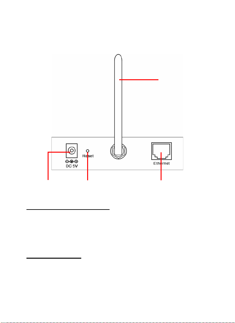
Rear Panel
4 Antenna
1 DC Power Connector 3 Network Cable Connector
1. DC Power Connector
The DC power input connector is located on the camera’s rear
panel, and is labeled DC5V 2.5A with a single jack socket to
supply power to the camera. Power will be generated when the
power supply is connected to a wall outlet.
2 Reset Button
2. Reset Button
Factory Reset will be initiated when the reset button is pressed
continuously for three seconds; meanwhile, the Link LED lights
up or blinks. Release the reset button and the Link LED will turn
off, indicating that the camera restores the factory default settings.
10
Page 21

When factory reset is completed, the configuration of camera will
return to the defaults as:
- IP address: 192.168.1.2
- Administrator’s login name: admin
- Password: admin
- Wireless status (for wireless model): disabled
3. Network Cable Connector
The camera’s rear panel features an RJ-45 connector for
connections to 10Base-T Ethernet cabling or 100Base-TX Fast
Ethernet cabling (which should be Category 5 twisted-pair cable).
The port supports the N-Way protocol and “AutoMDIX” function,
allowing the camera to automatically detect or negotiate the
transmission speed of the network.
4. Antenna (for wireless model)
The rotatable external antenna allows you to adjust its position to
obtain the maximum signal.
11
Page 22
2
HARDWARE
INSTALLATION
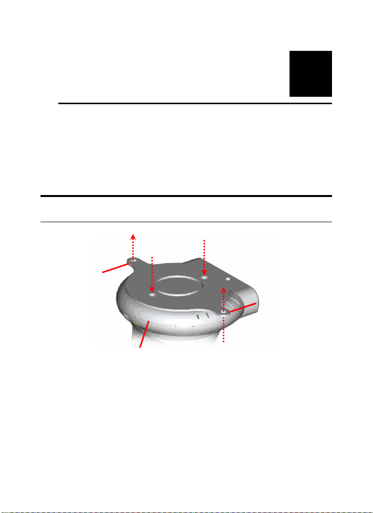
Attaching the Metal Clip
Wall screw
Ear
To attach the metal clip, remove the two rubber pads under the
base of the camera firstly. Place the metal clip onto the camera
base, and align the two holes of metal clip with two screw holes
on the camera base. Then, secure the metal clip with two screws
(provided in the package). There are two ears on each side of the
metal clip, allowing the camera to be mounted on the ceiling or
wall using two wall screws (provided in the package).
Base of the camera
Screw
Screw
12
Wall screw
Ear
Page 23
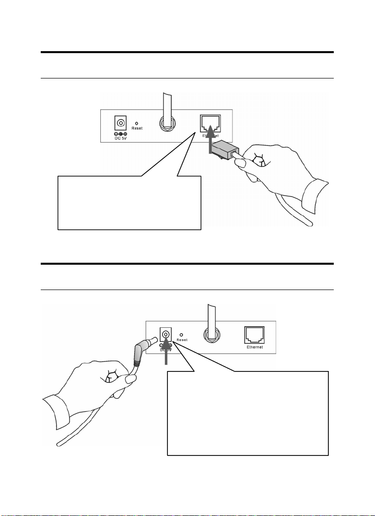
Connecting the Ethernet cable
Connect an Ethernet cable to the
network cable connector located
on the camera’s rear panel, and
then attach it to the network.
Attaching the Power Supply
Attach the external power supply to
the DC power input connector located
on camera’s rear panel, and then
connect it to your local power supply.
TIP: You can confirm power source is
supplied from the Power LED on the
camera is illuminated.
13
Page 24

3
SECURITY
To ensure the highest security and prevent unauthorized usage of
the camera the Administrator has the exclusive privilege to access
the System Administration for settings and control requirements
to allow users the level of entry and authorize the privileges for
all users. The camera supports multi-level password protection
and access to the camera is strictly restricted to defined the user
who has a “User Name” and “User Password” that is assigned by
the Administrator.
The administrator can release a public user name and password so
when remote users access the camera they will have the right to
view the image transmitted by the camera.
NOTE: The default settings of Administrator’s login name/password
are admin/admin, which are easily to be known by unauthorized
users. Therefore, it is strongly recommended to change the login
name and password when you are the first time to use the camera.
14
Page 25

4
APPLICATION OF
THE CAMERA
The camera can be applied in wide variety of applications. With
the built-in CPU, it can work as a standalone system that provides
a web-based solution transmitting high quality video images and
sounds for monitoring purposes. It can be managed remotely,
accessed and controlled from any PC desktop over the Intranet or
Internet via a web browser. With the easy installation procedure,
real-time live images will be available.
The following section will provide the typical applications for the
camera, and also includes some basic knowledge to assist in the
installation and configuration of the camera.
Applications:
Monitoring of local and remote places and objects such as
construction sites, hospitals, amusement parks, schools and
day-care centers through the use of a web browser.
View image f rom IPView Pro.
Configure the camera to save image or send-mail messages
with a short video clip.
15
Page 26
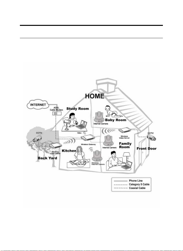
Application Diagrams of the Camera
Home Applications
16
Page 27
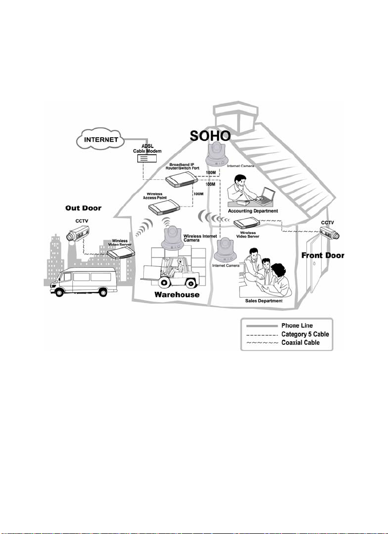
SOHO Applications
17
Page 28
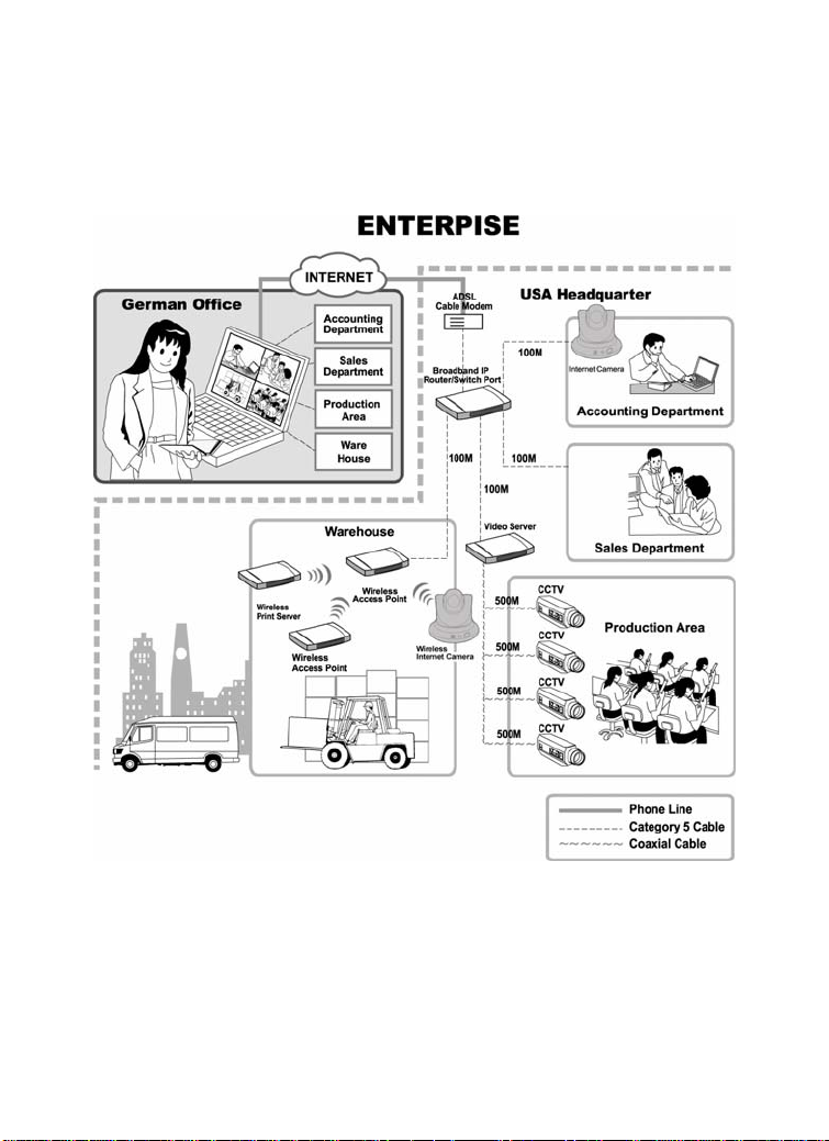
Enterprise Applications
18
Page 29

5
USING THE CAMERA
You can access and manage the camera through your web
browser. This chapter describes the Web Configuration Utility,
and provides the instructions on using the camera with a web
browser.
Web Configuration Utility
The camera must be configured through its built-in Web-based
Configuration. Whenever you want to configure the camera,
open your web browser (e.g. Internet Explorer in this manual),
and type the default IP address http://192.168.1.2 in the Address
bar and press [Enter]. When the login page appears, type
in the Name and Password box, and then click
Login.
admin
NOTE:
1. Extensive knowledge of LAN will be helpful in setting up the
camera.
2. The computer’s IP address must correspond with the camera’s IP
address in the same segment for the two devices to
communicate.
19
Page 30
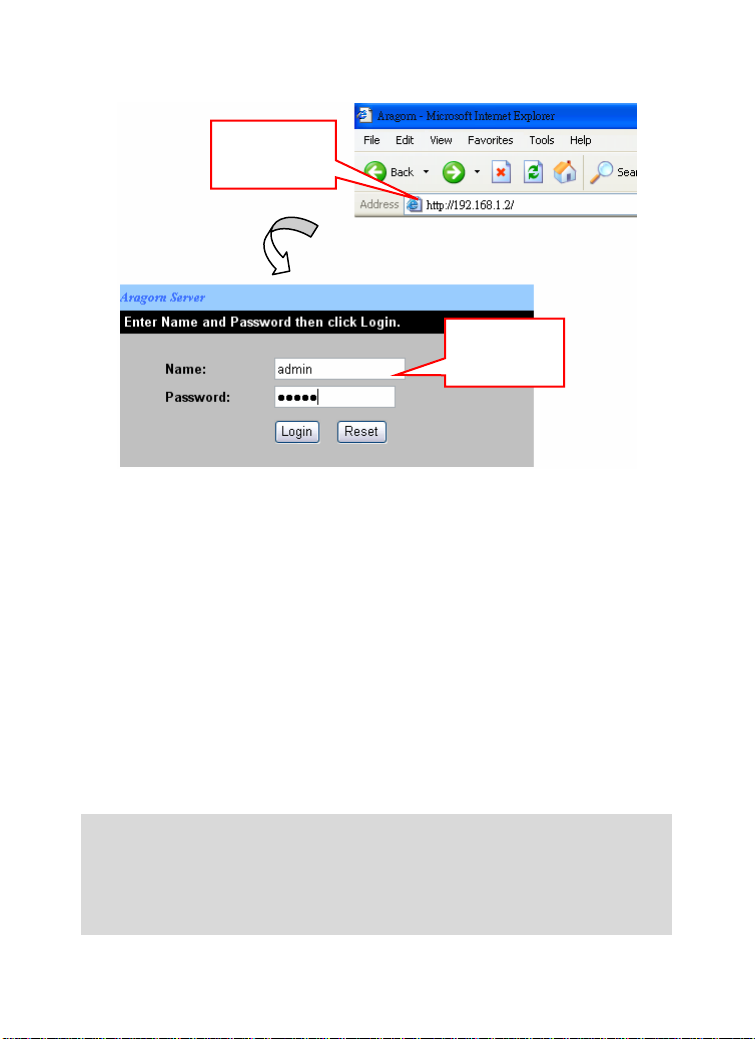
Enter the default
IP Address in the
Address bar.
Enter the default
username and
password.
Login Screen of Web Configuration Utility
“admin” is the default username and password of the camera, and
can be changed in the Web Configuration Utility.
After login, the Home window of the Configuration Utility will
appear as below, which includes three areas: Menu Bar, Video
Show Area, and Control Buttons.
NOTE: If you are denied to enter the Web Configuration Utility, the
following warning message will appear on the scr een. Please try to
enter the correct username and password again, or contact your
network administrator.
20
Page 31

Menu Bar
Video Show Area Control Buttons
Home Window
z Menu Bar – in the top of the window, containing six items
that allow you to setup the camera.
z Video Show Area – allows you to view the image from the
camera. You can adjust the viewing angle by using the
Slider bars.
z Control Buttons – contains some buttons that allow you to
control the camera’s viewing angle, position, audio, etc.
21
Page 32

Controlling and Viewing Video
In the Home window, you can control the camera through the
control buttons on the right side of the window. The real-time
image from the camera will be displayed in the Video Show Area.
Zoom On / Zoom Off
When you select ON, move your mouse to the Video Show Area,
and the cursor will change to the
in/out the image by clicking the left/right button on your mouse.
When the camera is in zoom out mode, click on any position of
the Video Show Area, then the position will be moved and
displayed in the center of the screen.
Adjust the Viewing Angle
To adjust the camera’s viewing angle, simply click the Slider bar
at the right-top corner of Video Show Area. Then, you can easily
move the camera’s lens to focus on the object that you want.
Clicking the Calibration button allows you return to the original
position saved in the camera.
The Pan Degree and Tilt Degree options allow you to increase/
decrease the changing range (5~90) when you click the buttons.
When you have saved position(s) in the camera, select the
position from the Go To pull-down list. The camera’s lens will
move to the position immediately.
icon. Then, you can zoom
22
Page 33

Adjust the Image Brightness
You can adjust the image brightness level through the Brightness
option. The range is from +5 t0 -5.
Audio Function
Click the Audio On button to enable the camera’s audio function;
click again to disable.
Capture Video and Still Images
Click the Start button to start record a video clip, and you can
specify the destiny folder to save the file by clicking the browse
button of the File path option.
Click the Snapshot button to capture a still image of the active
camera, and save it into your computer.
NightShot
The camera is equipped with a high-resolution CCD lens to
provide crystal clear images in real time, even at night. At dark
or low light situation, select the NightShot option to switch the
camera to deliver black & white images.
23
Page 34

Basic Setup
The Basic menu contains three steps that will guide you through
the basic configuration for the camera. Click Basic in the top
menu bar to start the step-by-step configuration.
Basic J Network
The first step is to configure networking settings of the
camera. According to your ISP’s service, select one from
the three connection types: LAN, PPPoE, and DDNS.
24
Page 35

If your network access uses a fixed IP address
or DHCP service, select this option and fill in the
LAN
PPPoE
DDNS
required data provided by your network
administrator in the fields of IP Address, IP
Subnet Mask, Gateway IP Address, and DNS
(Domain Name Server).
If your network access uses PPPoE (Point-toPoint Protocol over Ethernet), select this option.
Fill in the required data in the User Name and
Password fields, which are supplied by your
ISP. The IP Address is usually allocated
automatically.
The camera supports Dynamic DNS (DDNS)
feature, which allows you to assign a fixed host
and domain name to a dynamic Internet IP
address. Select Yes to enable this function, and
then fill in the required data in the User Name,
Password and Domain Name fields. Please
note that you have to sign up for DDNS service
with service providers before using this function.
When completed, click Next to continue.
25
Page 36

Basic J Camera Name
The second step is to setup a descriptive name for the camera.
When completed, click Next to continue.
26
Page 37

Basic J Time Zone
This step displays the current time setting of the camera. For
system management purpose, a correct time setting is critical to
have accurate time stamps on the system logs.
The Method pull-down menu allows you to setup the correct time
by getting time from the computer or time server (need an
Internet connection). In the Time Zone pull-down menu, select a
time zone according to your location.
When completed, click Apply.
NOTE: If you setup th ese st eps us ing incor rect networki ng settin gs, it
will pop up a warning message on the screen. Click OK to modify
these settings or Cancel to reserve the currently settings.
27
Page 38

Basic J Report
The last step provides some tips when you have Internet access
problems.
Click Start to complete your basic network configuration. When
completed, you are brought to the Home window.
NOTE: During the confi guration, you can return to Home window by
clicking the HOME button that is available in every page of the utility,
or exit the utility by clicking the LOGOUT button whenever you want.
28
Page 39

Advanced Setup
The camera will function fine after the Basic configuration,
however, you may wish to explore more advanced options. This
section explains each parameter and setting procedures for
advanced configuration of the camera. Move your mouse onto
the Advanced button, and it will automatically pop up a submenu
bar as below.
The submenu bar provides six submenu buttons: Video, Network,
Wireless (for wireless model), Tools, Account, and Timezone.
Each submenu button allows you to access advanced feature
settings, and is explained details in the following sections.
Advanced J Video
The Video submenu contains three options: Image Setting,
Location Setting and Motion Detection.
Image Setting
Click the Image Setting item of the Video submenu to bring up
the following page, which allows you to setup the image settings
of the camera.
29
Page 40

- Default Level: Select this option to use the default
image settings of the camera.
• Quality: You can setup the image quality from this
pull-down list. The default setting is High.
• Capture Resolution: You can setup the image
resolution when you capture a still image. The default
setting is VGA(640*480).
- Custom Level: Select this option when you want to
customize the image configuration.
• Capture Resolution: You can setup the image
resolution when you capture a still image. The default
setting is VGA(640*480).
• Frame Rate (fps): Select the optimal setting
depending on your network status. The higher setting
can obtain better quality; however, it will use more
resource within your network.
• Bit Rate: You can setup bit rate of the image by
selecting Kbps or Mbps. The setting range is
30
Page 41

4Kbps~3Mbps. The higher setting can obtain better
quality; however, it will use more resource within your
network.
• Camera Name: You can change the name of the
camera.
- Light Frequency: Adjust the light frequency to suit
your area of operation from the options either 50 Hz or
60 Hz (default).
Location Setting
Click the Location Setting item of the Video submenu to bring
up the following page, which allows you to setup the video
control settings of the camera.
31
Page 42

- Upside Down: Display the image in a vertical mirror
mode.
- Mirrored: Display the image in a horizontal mirror
mode.
- Location: When you have saved the position in the
camera, select the location from the pull-down list, and
then click Apply. The camera’s lens will move to the
location immediately.
Motion Detection
Click the Motion Detection item of the Video submenu to bring
up the following page, which allows you to setup the motion
detection settings of the camera.
32
Page 43

- Motion: Check this option to enable motion detection
function of your camera. Once enabled, you can setup
the detecting region by giving a name for respective
Zone# (#: 1/2/3). Then, build the Zone window(s) using
your mouse to setup the detecting area(s). In addition,
move the slide bars to adjust the Sensitivity level and
Percentage level for detecting motion to record video or
to send e-mail.
- Open MSD: Click this button to bring up a dialog
window that displays the detected motion event(s) of
Zone # (#: 1/2/3).
33
Page 44

Advanced J Network
The Network submenu contains three options: LAN, PPPoE and
DDNS. The settings in these three options are the same as in the
Network under Basic configuration. (The settings here are the
same as the configuration made in Basic menu.)
LAN
Click the LAN item of the Network submenu to bring up the
following page.
If your network access uses a fixed IP address or DHCP service,
select this option and fill in the required data provided by your
network administrator in the fields of IP Address, IP Subnet
Mask, Gateway IP Address, and DNS (Domain Name Server).
34
Page 45

PPPoE
Click the PPPoE item of the Network submenu to bring up the
following page.
If your network access uses PPPoE (Point-to-Point Protocol over
Ethernet), select this option by checking the Yes item. Fill in the
required data in the User Name and Password fields, which are
supplied by your ISP. The IP Address is usually allocated
automatically.
35
Page 46

DDNS
Click the DDNS item of the Network submenu to bring up the
following page.
The camera supports Dynamic DNS (DDNS) feature, which
allows you to assign a fixed host and domain name to a dynamic
Internet IP address. Select Yes to enable this function, and then
fill in the required data in the User Name, Password and
Domain Name fields. Please note that you have to sign up for
DDNS service with service providers before using this function.
36
Page 47

Advanced J Wireless (for wireless model)
If you use a wireless camera, you can configure the respective
settings in the Wireless submenu, which contains two options:
Setting and Site Survey.
Setting
Click the Setting item of the Wireless submenu to bring up the
following page.
- Wireless: The default setting is Disable. Select
Enable/Disable to start/stop the wireless function of the
camera.
- Connection Mode: Use this option to determine the
type of wireless communication for the camera. There
37
Page 48

are two choices: Infrastructure mode and Ad-Hoc
mode.
- SSID: SSID (Service Set Identity ) is the name assigned
to the wireless network. It will auto-detect and display
the SSID of wireless network connected in this box.
This default setting will let the camera connect to ANY
access point under the infrastructure network mode.
- Channel: This pull-down menu provides the wireless
channel for communication. A “channel” is a range of
frequencies to be used in communication between the
camera and access point in Infrastructure mode, or the
camera and PC/Notebook in Ad-Hoc mode. Select the
appropriate channel from the list provided depending on
the regulatory region where the unit is sold.
- Security Mode: Wireless network communications can
be intercepted easily. This option will help you protect
your wireless network.
- Authentication: Open communicates the key across the
network. Shared allows communication only with other
devices with identical WEP settings.
- Encryption Mode: This option allows you to configure
the setting of data encryption. The WEP key must be set
before the data encryption is enforced.
- Key Format: To enable WEP Encryption, you should
decide the encryption format first by selecting the
ASCII or HEX option, and then input the WEP key (in
the following Key 1~4 box).
- Pre-Shared Key: This is used to identify each other in
the network. Enter the name in the Pre-Shared Key box,
and this name must match the Pre-Shared Key value in
the remote device.
38
Page 49

Site Survey
Click the Site Survey item of the Wireless submenu to bring up
the following page.
This field displays the available networks. To connect one
wireless network, scroll up and down in the list and highlight the
desired network, and click the Connect button.
You can click Refresh to re-search the available networks.
39
Page 50

Advanced J Tools
The Tools submenu contains three options: Recording, Port and
Mail.
Recording
Click the Recording item of the Tools submenu to bring up the
following page, which allows you to setup the record function of
the camera.
40
Page 51

- Upload image to Network share folder: Enable this
function by checking the item, and then configure the
following settings in this field.
• Login Method: If the network share folder allows you
to login using Anonymous, you will be able to upload
the images without enter the User Name and Password.
If not, you have to use the correct settings to enter the
folder.
• Login User: Enter the user name in this field.
• Password: Enter the user password in this field.
• Path: Enter an existing folder name in this field, and
the images will be uploaded to the given folder.
Example: \\192.168.5.2\SHARE (the shared PC’s IP
is 192.168.5.2; the shared folder named is SHARE).
Then, you can select the upload mode and recording method from
the following two fields: Shared Folder Mode and Recording
Method.
• Shared Folder Mode: You can set up this option by
selecting None, Recording File Number, or Shared
Folder Size.
• Recording Method:
Always: The recorded images will be always uploaded
to the network share folder.
Schedule: You can manage the uploading task by
configuring the Day and Time options
Smart Recording: Allows you to upload the recorded
image only, and skip the empty files. To select this
mode, you have to enable and configure the Motion
Detection option first.
41
Page 52

Port
Click the Port item of the Tools submenu to bring up the
following page, which allows you to setup the ports used to
transmit the camera’s data.
- Enable UPnP Control Point: Setup the Web port to
transmit the camera’s image data. The default setting is
port 80.
- Non UPnP: When you select this option, you can set up
the following items manually.
• Web Port: Setup the Web port to transmit the
camera’s image data. The default setting is port 80.
• AV Control Port: Setup the transmission of streaming
data within the network. The default setting is port
5000.
• AV Streaming Port: The default setting is port 5001.
• IP View Lite Port: The default setting is port 5100.
42
Page 53

Mail
Click the Mail item of the Tools submenu to bring up the
following page, which allows you to setup e-mail function of the
camera.
When you select By E-mail, the system will enable the alert
function that notifies you the events of IP Change or Motion
Detection by sending an e-mail. If you select None, the system
will do nothing.
- By E-mail: Configure the following settings. This field
contains the six basic settings for your e-mail server.
• SMTP Login Name: Enter the user name in this field
to login receiver’s e-mail server.
• SMTP Password: Enter the user password in this
field to login receiver’s e-mail server.
43
Page 54

• SMTP (mail) Server: SMTP (Simple Mail Transfer
Protocol) is a protocol for sending e-mail messages
between servers you need to input the mail server
address in this field.
• Return Email Address: Enter the e-mail address of
the user who will send the e-mail.
• Recipient Email Address: Enter the e-mail address of
the user who will receive the e-mail.
• SMPT Port: Enter the e-mail port used in your
computer. The default setting is port 25.
- Motion Detection Set Skip Time: You can setup the
duration of motion detecting.
NOTE: You can click t he Test button to test the e-mail account you
provided. To test, you have to enable and configure the Motion
Detection option first.
44
Page 55

Advanced J Account
The Account submenu contains the options that allow you to
add/delete users. Also, you can manage the users of the camera.
- User Name: Enter the user name in this field.
- Password: Enter the user password in this field.
- Retype Password: Enter the user password again to
confirm the password.
When completed, click Apply to activate the user’s account.
The following User List displays the existing users of the camera.
You can modify and delete a user by click the respective icon.
45
Page 56

Advanced J Timezone
The Timezone submenu displays the current time setting of the
camera. For system management purpose, a correct time setting
is critical to have accurate time stamps on the system logs.
- Method: Allow you to setup the correct time by getting
time from the computer or time server (need an Internet
connection).
- Time Zone: Select a time zone according to your
location.
46
Page 57

Maintenance
The Maintenance menu contains two submenus: Configuration
and Firmware Upload. Move your mouse onto the
Maintenance button, and it will automatically pop up a submenu
bar as below.
Maintenance J Configuration
The Configuration submenu contains four options: Idle Time,
Reset Default, Reboot and Status.
Idle Time
Click the Idle Time item of the Configuration submenu to bring
up the following page, which allows you to setup the idle time of
the camera.
47
Page 58

- Administrator Inactivity Timer: location. If the user
does nothing within the specified time in this option, the
system would automatically logout. The idle time must
be larger than 0.
Reset Default
Click the Reset Default item of the Configuration submenu to
bring up the following page, which allows you to load the default
settings of the camera.
Clicking Reset allows you to resume the factory default settings
of the camera. This function is the same as pressing the Reset
button on the camera.
48
Page 59

Reboot
Click the Reboot item of the Configuration submenu to bring up
the following page, which allows you to restart the camera.
Click Reboot to restart the camera.
After reboot, both the Power LED and Link LED on the front
panel will light on, and then you can enter your Name and
Password to login.
49
Page 60

Status
Click the Status item of the Configuration submenu to bring up
the following page, which displays the current configuration of
the camera.
The Status option contains information of the camera, including
its basic status and the networking status.
50
Page 61

Maintenance J Firmware Upload
The Firmware Upload submenu allows you to update the
firmware of the camera once you obtained a latest version of
firmware.
Click Browse to point to the firmware file saved in your computer,
and then click Upload. The system start to upgrade the firmware,
and it will ask you to restart the camera. Click Restart when
prompted.
NOTE: It will take a few minutes to update firmware. Please w ait to
complete the procedure; you can then reboot the camera.
51
Page 62

Logout
Click the LOGOUT button to exit the Web Configuration Utility,
and it will return to the login screen of the utility.
52
Page 63

Help
Click the HELP button to bring up a window, providing you with
the general help information to control the camera.
53
Page 64

6
FFDSHOW & AVISAVIOR
This chapter describes FFdshow and AVISavior, which are
provided in the Installation CD. FFdshow allows you to play the
recorded video files on your computer. AVISavior allows you to
fix the damaged recorded video files.
Installing FFdshow
Step 1
Insert the CD-ROM into the CD-ROM drive to initiate the autorun program. The menu screen will appear as below:
54
Page 65

Step 2
Click the FFdshow Install item, and select the desired language
in the pop-up dialog window.
Then, the InstallShield Wizard will appear, click Next in the
welcome screen.
55
Page 66

Step 3
Read and accept the License Agreement; then, click I Agree.
Step 4
Choose the components to be installed. If no specific requirement,
leave the default setting and click Next.
56
Page 67

Step 5
Choose the destination location. If no specific requirement, leave
the default setting and click Install.
Step 6
The InstallShield Wizard starts to install the software, and the
progress bar indicates the installation is proceeding. When
completed, click Next. Then, click Finish.
57
Page 68

Configuration of FFdshow
Before playing the recorded video file, you have to change the
following settings in FFdshow:
- Enable the Subtitles function.
- Set the Error resilience option to none.
1. Click Start > Programs > ffdshow > Configuration to open
the ffdshow properties window.
2. Select to check the Subtitles item.
3. Select the Miscellaneous item, and then set the Error
resilience option to none.
Check this item.
Set this option to none.
58
Page 69

Playing the Video
Since you have recorded video files from the camera, you can
play the video files simply using Windows Media Player in your
computer.
1. Find the video file saved in the computer.
2. Double-click the file, and it will open Windows Media Player
(as default in Microsoft Windows) to play the video file.
NOTE: By default, the destination folder to save the recorded video
files is :\Program\IPView Pro\, and the file will be named as
xxxxxxxx_yyyyyy.avi (where x is date and y is time). Also, it will
automatically create a subtitle file named as xxxxxxxx_yyyyyy.sub
(the same date/time settings with the corresponded .avi file). The
destination folder can be changed in the Rec ording Configure option
of IPView Pro.
59
Page 70

Fixing the Video File
If, unfortunately, the recorded video restored in your computer is
damaged, you can try to fix it using AVISavior. To launch the
utility, insert the CD-ROM into the CD-ROM drive to initiate the
auto-run program. The menu screen will appear as below:
Click the AVISavior item, and the following window will appear
on the screen.
60
Page 71

First, set up the File Fixing Options by checking the “Create a
new AVI file for fixing” or “Fix with raw AVI file” item.
Selecting the former one will create a new AVI file in the
computer when fixed; selecting the latter one will overwrite the
original file when fixed.
Then, select the AVI file that you want to fix. Click the Select
your AVI File button to bring up a dialog window, which allows
you to assign the AVI file to be fixed. When selected, the path of
the AVI file will appear in the box, as shown below.
Click the Start to Fix button to start fixing.
61
Page 72

7
IPVIEW PRO
This chapter describes IPView Pro, which is a powerful software
application designed with a user-friendly interface for ease of
control and navigation requirements.
Installation
Step 1
Insert the CD-ROM into the CD-ROM drive to initiate the autorun program. The menu screen will appear as below:
62
Page 73

Step 2
Click the IPView Pro item to activate the InstallShield Wizard.
Click Next in the welcome screen.
Step 3
Read and accept the License Agreement; then, click Yes.
63
Page 74

Step 4
Choose the destination location. If no specific requirement, leave
the default setting and click Next.
Step 5
The InstallShield Wizard starts to install the software, and the
progress bar indicates the installation is proceeding.
64
Page 75

Step 6
When the Digital Signature warning screen appears, click
Continue Anyway.
Step 7
Click Finish to complete the installation.
65
Page 76

Getting Started
This section describes the User Interface of IPView Pro, with
detailed procedures for using the application.
To launch IPView Pro, click Start > Programs > IPView Pro >
IPView Pro. The main screen will appear as below:
NOTE: IPView Pro requires the system’s resolution setting up to
1024x768. Please configure the resolution to 1024x768 or higher;
otherwise, it may shows incomplete screen when launching the
program.
66
Page 77

Item Feature
NO.
Item Description
Date/Time Show current date/time.
Status Mode
Window
Show the camera’s status in this window.
Click the Change Status Mode button (
the right lower corner of the window to chan ge th e
display mode:
Camera list mode Camera information mode
) on
View
Window
View Mode
Buttons
Show the camera’s view in this window.
Select the view mode from these buttons.
Show one camera in View Window.
Show four cameras in View Window.
Show six cameras in View Window with
the first one as the major view.
Show eight cameras in View Window with
the first one as the major view.
Show nine cameras in View Window.
Show ten cameras in View Window with
the first two as the major views.
Show thirteen cameras in View Window
with the first one as the major view.
67
Page 78

Key Lock
Button
Power Button Click to ex it or minimize IPView Pro.
Pan/Tilt
Control Panel
Record
Button
Play Button Play the recorded video file in the computer.
Click to lock/unlock the camera. When locked,
the user cannot operate any camera.
When the camera is added, the Pan/Tilt control
buttons will appear on the panel, as shown below:
buttons to adjust the camera’s viewing angle to Up/
Down/Left/Right/Left-Up/Left-Down/RightUp/Right-Down.
in the camera, click the Swing button to control
the camera swinging from one position to another
position.
the default position.
Record video clip of the selected camera and save
it in the computer. The storage position can be
configured in System Configuration. When you
click the button, you can select Manual Record,
Schedule Record, or Motion Record.
Show sixteen cameras in View Window.
Show the selected camera in full screen
view.
Enable displaying the video views in
circles.
/ / / / / / / : Click these
: Once you have saved two (or more) positions
: Click the Home button to return the camera to
Configuration
Click to enter the System Configuration.
Button
68
Page 79

Using IPView Pro
Adding a Camera
To add a camera:
1. Click the Configuration button
Configuration.
If you are not sure of the camera’s IP address, you can click
Search to search the available camera(s) within the network.
to enter the System
69
Page 80
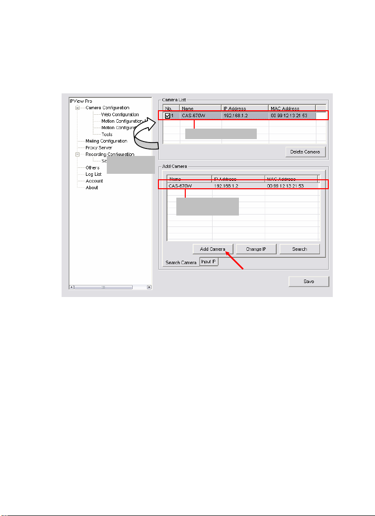
2. Select the camera you want by highlighting it, and then click
Add Camera. Enter the User Name and Password when
prompted.
The camera is added.
Click the Add
Camera button.
The camera found
within the network.
3. Click Save, and then click the Configuration button to return
to View Window. The selected camera’s video will be
displayed now.
70
Page 81

Alternately, you can add a camera by entering its IP address:
4. Select the Input IP tab.
The camera is added.
Click the Add
Camera button.
Enter the camera’s
IP address and Port.
5. Enter the camera’s IP address (default: 192.168.1.2) and Port
(default: 80), and then click Add Camera.
6. Click Save, and then click the Configure button to return to
View Window. The selected camera’s video will be
displayed now.
71
Page 82

Removing a Camera
To remove the camera from the list:
1. Select the camera you want to remove.
2. Click Delete Camera.
Viewing a Camera
From the View Modes of the panel, you can select one-camera
mode or other modes to display your video. IPView Pro
allows a maximum of 16 cameras for viewing.
For example, if you use only one camera, select one-camera
mode (
figure 1.
If there are four cameras, select four-camera mode (
and the View Window will display the view as figure 2.
), and the View Window will display the view as
),
Figure 1. Figure 2.
72
Page 83

Recording Video
play
IPView Pro allows you to record the video clip and save it in your
computer through the following methods: Manual Record,
Schedule Record, and Motion Record.
When you click the Record button and select Manual Record, it
will start recording. Click the button again to stop. If you select
Schedule Record or Motion Record, the system will record the
video clip according to the settings in System Configuration.
Playing Recorded Video
The recorded video clips are saved in your computer, and can be
played using Windows Media Player. To start playback, simply
click the Play button on the panel, and the following dialog screen
will appear, allowing you to select the file to playback.
Select one file
back.
to
The folder that stores
the recorded file.
Select the recorded file in the computer, and then click OK.
73
Page 84

Configuring the System
Clicking the Configuration button on the panel allows you to
configure the system settings, and the System Configuration
Screen will appear in the View Window as shown below. Once
configured, click Save to save the settings, and then click the
Configuration button again to exit configuration.
System Configuration Screen
74
Page 85

Camera Configuration
In this field, you can add/delete the camera (as described in the
previous section). Also, you can configure the following settings:
Web Configuration
In the left column, selecting the Web Configuration item will
launch the Web Configuration Utility in View Window.
You can configure these settings according to the description in
Chapter 5, Using the Camera. Click Back to exit the Web
Configuration Utility.
75
Page 86

Motion Configuration-1
The Motion Configuration-1 item provides the commands for
motion detection control. Before configuring, you should select
one camera from the pull-down menu.
Select one camera.
- Detect Region: When you select the Full picture option, the
camera will monitor the whole area.
Sensitivity Level: Move the slide bar to adjust the
-
sensitivity level for detecting motion to record video.
76
Page 87

Motion Configuration-2
The Motion Configuration-2 item allows you to configure to the
alarm and e-mail setting.
Invoke Alarm: Select this option to enable alarm when
-
some motion detected by the system.
-
Send e-mail: When this option is checked, click the Mailing
Configuration in the left column to enter the required
information (see the following section).
- Play music: Selecting this option allows the system to play
music. You can select a music file by clicking the Browse
music file button, and set up the interval time in the following
pull-down menu (1 to 20 seconds).
77
Page 88

Tools
The Tools item allows you to configure to the alarm and e-mail
setting.
Reset: Restore the original setting of your camera. Do you
-
really want to reset this device? Click Yes in the pop-up
dialog box to confirm.
-
Factory Reset: Restore the factory default settings of the
camera. Do you really want to factory reset this device?
Click Yes in the pop-up dialog box to confirm.
Update Firmware: When new firmware is available, you
-
can upgrade it using this option. Click Browse to find the
firmware file, and then click Update.
78
Page 89

Mailing Configuration
When Motion Detection function is enabled and the Send e-mail
option is checked, you should enter the required information in
the respective fields.
Mail Server: Enter the mail server address that is used to
-
send your e-mail.
Mail From/To: Enter the sender’s/receiver’s e-mail address.
-
Subject: Enter the title of the e-mail.
-
-
User Name/Password: Enter the user name/password to
login the mail server.
Interval Time: Enter a number in this box to setup the time
-
(in second) to send E-mail regularly.
79
Page 90

Proxy Server
Check the Proxy Server option and enter the required settings in
the Address and Port boxes to enable and use the Proxy Server
function.
80
Page 91

Recording Configuration
In this field, you can configure the storage settings.
Log Storage:
-
• Reserved HDD Space For MS-Windows OS – You can
reserve 500 MB to 1000 MB hard disk space for the
program.
• Each Recording File Size – If the recorded video files
reach the file size limit, video images will be recorded
into another file automatically. The available settings are
from 10 MB to 50 MB.
81
Page 92

• Storage List – The destination folder to save the
recorded video file can be specified here. Click Modify to
change the current path setting; click Add to add a new
destination folder; click Delete to remove a selected path
setting. Please note that you are not allowed to delete a
path setting if there is only one setting in the list.
-
Recycle: You can check this option to clear the files when
the unreserved space of your hard disk is filled. The available
settings are from 200 MB to 50000 MB.
Schedule-Recording Configuration
This recording function will work after you have enabled
respective settings in the Schedule mode. The recording schedule
can be defined by Date Mode or Week Mode.
-
Date Mode: First, select the camera desired from the pull-
down menu. Then, setup the time in the Start/Stop fields.
Click Add to add the recording schedule to the list. Click
Save to save the settings.
82
Page 93

- Week Mode: First, select the camera desired from the pull-
down menu. Then, setup the time in the Start/Stop fields,
and select the weekday from the buttons. Click Add to add
the recording schedule to the list. Click Save to save the
settings.
Weekday buttons.
83
Page 94

Others
When multiple cameras connected, this option allows the system
to display these views as the main view in circles according to
your time settings. The range of Time interval of scan is from 1
to 20 seconds.
84
Page 95

Log List
This filed displays the user(s) information, which includes the
Date, MAC address, and the brief description of events.
85
Page 96

Account
This filed allows the system administrator to manage the account
information. Selecting Login Password check to enable the
system to check the password when login.
86
Page 97

About
This filed provides information of the software application.
87
Page 98

8
APPENDIX
A. Frequently Asked Questions
Internet Camera Features
Q: What is an Internet Camera?
A: Internet camera is a standalone system connecting directly to
an Ethernet or Fast Ethernet network and supported by the
wireless transmission based on the IEEE 802.11g standard. It is
different from the conventional PC camera, Internet camera is an
all-in-one system with built-in CPU and web-based solutions
providing a low cost solution that can transmit high quality video
images for monitoring. The camera can be managed remotely,
accessed and controlled from any PC/Notebook over the Intranet
or Internet via a web browser.
Q: How many users are allowed to access this Internet camera
simultaneously?
A: Maximum number of users that can log onto the camera at the
same time is 10. Please keep in mind the overall performance of
88
Page 99

the transmission speed will slow down when many users are
logged on, it is because that all the users share the same resources.
Q: What algorithm is used to compress the digital image?
A: The camera utilizes the MPEG-4 image compression
technology providing high quality images for users. MPEG-4 is
adopted since it is a standard for image compression and can be
applied to various web browsers and software applications.
Q: Can I change the wireless antenna attached to the camera?
A: The wireless antenna can be changed for a variety of reasons
such as extending the wireless transmission range, however,
please consult authorized distributors before attempting as the
connectors must be SMA connector type.
Q: What is the wireless transmission range for the camera?
A:
Generally the wireless distance can go up to 100 meters
indoors and up to 300 meters outdoors. The range is limited
by the number of walls, ceilings, or other objects that the
wireless signals must pass through. Typical ranges vary
depends on the types of materials and background Radio
Frequency (RF) noise in your home or business and the
configuration setting of your network environment.
Internet Camera Installation
Q: Can the Internet Camera be used out-doors?
A: The camera is not weatherproof. It needs to be equipped with
a weatherproof case to be used outdoors and it is not
recommended.
89
Page 100

Q: What network cabling is required for the camera?
A: The camera uses Category 5 UTP cable with RJ-45 connector,
which allows 10 Base-T and 100 Base networking.
Q: Can the camera be setup as a PC-cam on the computer?
A: No, the camera is an Internet Camera used only on Ethernet
and Fast Ethernet network and supported by wireless transmission.
Q: Can the camera be connected on the network if it consists of
only private IP addresses?
A: The camera can be connected to LAN with private IP
addresses.
Q: Can the camera be installed and work if a firewall exists on
the network?
A: If a firewall exists on the network, port 80 is open for ordinary
data communication. However, since the camera transmits image
data, the default ports 5000, 5001 and 5100 are also required.
Therefore, it is necessary to open ports 5000, 5001 and 5100 of
the network for remote users to access the camera.
90
 Loading...