

SMC Networks SMCWBR14S-N5,SMCWBR14-N5 User Manual

USER GUIDE
BARRICADE™ N
150/300Mbps 4-Port Wireless Broadband Router
SMCWBR14S-N5, SMCWBR14-N5

Wireless Broadband Router
User Guide
No. 1, Creation Road III,
Hsinchu Science Park,
30077, Taiwan, R.O.C.
TEL: +886 3 5770270
Fax: +886 3 5780764
August 2011
Pub. # 149100000009W
SMC-UG-0811-02

Information furnished by SMC Networks, Inc. (SMC) is believed to be accurate and reliable.
However, no responsibility is assumed by SMC for its use, nor for any infringements of patents or
other rights of third parties which may result from its use. No license is granted by implication or
otherwise under any patent or patent rights of SMC. SMC reserves the right to change specifications
at any time without notice.
Copyright © 2011 by
SMC Networks, Inc.
No. 1 Creation Road III,
Hsinchu Science Park,
30077, Taiwan, R.O.C.
All rights reserved
Trademarks:
SMC is a registered trademark; and Barricade, EZ Switch, TigerStack, TigerSwitch, and TigerAccess
are trademarks of SMC Networks, Inc. Other product and company names are trademarks or
registered trademarks of their respective holders.

WARRANTY AND PRODUCT REGISTRATION
To register SMC products and to review the detailed warranty statement,
please refer to the Support Section of the SMC Website at http://
www.smc.com.
– 4 –

COMPLIANCES
FEDERAL COMMUNICATION COMMISSION INTERFERENCE STATEMENT
This equipment has been tested and found to comply with the limits for a
Class B digital device, pursuant to part 15 of the FCC Rules. These limits
are designed to provide reasonable protection against harmful interference
in a residential installation. This equipment generates, uses and can
radiate radio frequency energy and, if not installed and used in accordance
with the instructions, may cause harmful interference to radio
communications. However, there is no guarantee that interference will not
occur in a particular installation. If this equipment does cause harmful
interference to radio or television reception, which can be determined by
turning the equipment off and on, the user is encouraged to try to correct
the interference by one or more of the following measures:
◆ Reorient or relocate the receiving antenna
◆ Increase the separation between the equipment and receiver
◆ Connect the equipment into an outlet on a circuit different from that to
which the receiver is connected
◆ Consult the dealer or an experienced radio/TV technician for help
This device complies with Part 15 of the FCC Rules. Operation is subject to
the following two conditions: (1) This device may not cause harmful
interference, and (2) this device must accept any interference received,
including interference that may cause undesired operation.
FCC Caution: Any changes or modifications not expressly approved by the
party responsible for compliance could void the user's authority to operate
this equipment.
N
OTE
:
The manufacturer is not responsible for any radio or TV interference
caused by unauthorized modifications to this equipment. Such
modifications could void the user’s authority to operate the equipment.
– 5 –

C
OMPLIANCES
IMPORTANT NOTE:
FCC RADIATION EXPOSURE STATEMENT
This equipment complies with FCC RF radiation exposure limits set forth for
an uncontrolled environment. This device and its antenna must not be colocated or operating in conjunction with any other antenna or transmitter.
“To comply with FCC RF exposure compliance requirements, this grant is
applicable to only Mobile Configurations. The antennas used for this
transmitter must be installed to provide a separation distance of at least 20
cm from all persons and must not be co-located or operating in conjunction
with any other antenna or transmitter.”
CE MARK WARNING
SMC contact for these products in Europe is:
SMC Networks Europe,
C/Fructuós Gelabert 6-8, 2
Edificio Conata II,
08970 - Sant Joan Despí, Barcelona, Spain.
o
, 2a,
This is a class B product. In a domestic environment, this product may
cause radio interference, in which case the user may be required to take
adequate measures.
NATIONAL RESTRICTIONS
This device is intended for home and office use in all EU countries (and
other countries following the EU directive 1999/5/EC) without any
limitation except for the countries mentioned below:
Country Restriction Reason/Remark
Bulgaria None General authorization required for outdoor use and
France Outdoor use
italy None If used outside of own premises, general
Luxembourg None General authorization required for network and
Norway Implemented This subsection does not apply for the geographical
limited to 10 mW
e.i.r.p. within the
band 2454-2483.5
MHz
public service
Military Radiolocation use. Refarming of the 2.4 GHz
band has been ongoing in recent years to allow
current relaxed regulation. Full implementation
planned 2012
authorization is required
service supply(not for spectrum)
area within a radius of 20 km from the centre of NyÅlesund
Russian
Federation
N
OTE
None Only for indoor applications
:
Do not use the product outdoors in France.
– 6 –

C
OMPLIANCES
EUROPE - EU DECLARATION OF CONFORMITY
This device complies with the essential requirements of the R&TTE
Directive 1999/5/EC. The following test methods have been applied in
order to prove presumption of conformity with the essential requirements
of the R&TTE Directive 1999/5/EC:
◆ EN 60950-1:2006 + A11: 2009
Safety of Information Technology Equipment.
◆ EN 300 328 V1.7.1: 2006-10
Electromagnetic compatibility and Radio spectrum Matters (ERM);
Wideband transmission systems; Data transmission equipment
operating in the 2,4 GHz ISM band and using wide band modulation
techniques; Harmonized EN covering essential requirements under
article 3.2 of the R&TTE Directive.
◆ EN 301 489-17 V1.8.1/ 2008-04
EN 301 489-17 V2.1.1/ 2009-05
Electromagnetic compatibility and Radio spectrum Matters (ERM);
Electromagnetic Compatibility (EMC) standard for radio equipment and
services; Part 17: Specific conditions for 2.4 GHz wideband
transmission systems and 5 GHz high performance RLAN equipment.
◆ EN 55022: 2006 + A1: 2007
Limits and methods of measurement of radio disturbance
characteristics of information technology equipment.
◆ EN 55024: 1998 + A1: 2001 + A2: 2003
Information technology equipment immunity characteristics limits and
methods of measurement.
◆ EN 62311: 2008
Assessment of electronic and electrical equipment related to human
exposure restrictions for electromagnetic fields (0 Hz - 300 GHz).
This device is a 2.4 GHz wideband transmission system (transceiver),
intended for use in all EU member states and EFTA countries, except in
France and Italy where restrictive use applies.
In Italy the end-user should apply for a license at the national spectrum
authorities in order to obtain authorization to use the device for setting up
outdoor radio links and/or for supplying public access to
telecommunications and/or network services.
This device may not be used for setting up outdoor radio links in France
and in some areas the RF output power may be limited to 10 mW EIRP in
the frequency range of 2454 - 2483.5 MHz. For detailed information the
end-user should contact the national spectrum authority in France.
– 7 –
C
OMPLIANCES
This equipment may be operated in:
The official CE certificate of conformity can be downloaded by selecting the
relevant model/ part number from www.smc.com -> support -> download.
Bulgarian
Български
Czech
Česky
Danish
Dansk
Dutch
Nederlands
English Hereby, Manufacturer, declares that this Radio LAN device is in compliance with the
Estonian
Eesti
Finnish
Suomi
French
Français
German
Deutsch
Greek
Ελληνική
Hungarian
Magyar
Italian
Italiano
Latvian
Latviski
Lithuanian
Lietuvių
С настоящето, SMC Networks декларира, че това безжично устройство е в
съответствие със съществените изисквания и другите приложими разпоредби на
Директива 1999/5/EC.
Manufacturer tímto prohlašuje, že tento Radio LAN device je ve shodě se základními
požadavky a dalšími příslušnými ustanoveními směrnice 1999/5/ES.
Undertegnede Manufacturer erklærer herved, at følgende udstyr Radio LAN device
overholder de væsentlige krav og øvrige relevante krav i direktiv 1999/5/EF
Hierbij verklaart Manufacturer dat het toestel Radio LAN device in overeenstemming is
met de essentiële eisen en de andere relevante bepalingen van richtlijn 1999/5/EG
Bij deze Manufacturer dat deze Radio LAN device voldoet aan de essentiële eisen en aan
de overige relevante bepalingen van Richtlijn 1999/5/EC.
essential requirements and other relevant provisions of Directive 1999/5/EC.
Käesolevaga kinnitab Manufacturer seadme Radio LAN device vastavust direktiivi 1999/
5/EÜ põhinõuetele ja nimetatud direktiivist tulenevatele teistele asjakohastele sätetele.
Valmistaja Manufacturer vakuuttaa täten että Radio LAN device tyyppinen laite on
direktiivin 1999/5/EY oleellisten vaatimusten ja sitä koskevien direktiivin muiden ehtojen
mukainen.
Par la présente Manufacturer déclare que l'appareil Radio LAN device est conforme aux
exigences essentielles et aux autres dispositions pertinentes de la directive 1999/5/CE
Hiermit erklärt Manufacturer, dass sich dieser/diese/dieses Radio LAN device in
Übereinstimmung mit den grundlegenden Anforderungen und den anderen relevanten
Vorschriften der Richtlinie 1999/5/EG befindet". (BMWi)
Hiermit erklärt Manufacturer die Übereinstimmung des Gerätes Radio LAN device mit den
grundlegenden Anforderungen und den anderen relevanten Festlegungen der Richtlinie
1999/5/EG. (Wien)
την παρουσα Manufacturer δηλωνει οτι radio LAN device συμμορφωνεται προσ τισ
με
ουσιωδεισ απαιτησεισ και τισ λοιπεσ σχετικεσ διαταξεισ τησ οδηγιασ 1999/5/εκ.
Alulírott, Manufacturer nyilatkozom, hogy a Radio LAN device megfelel a vonatkozó
alapvetõ követelményeknek és az 1999/5/EC irányelv egyéb elõírásainak.
Con la presente Manufacturer dichiara che questo Radio LAN device è conforme ai
requisiti essenziali ed alle altre disposizioni pertinenti stabilite dalla direttiva 1999/5/CE.
Ar šo Manufacturer deklarē, ka Radio LAN device atbilst Direktīvas 1999/5/EK būtiskajām
prasībām un citiem ar to saistītajiem noteikumiem.
Šiuo Manufacturer deklaruoja, kad šis Radio LAN device atitinka esminius reikalavimus ir
kitas 1999/5/EB Direktyvos nuostatas.
– 8 –

C
OMPLIANCES
Maltese
Malti
Polish
Polski
Portuguese
Português
Romanian
Romană
Slovak
Slovensky
Slovenian
Slovensko
Spanish
Español
Swedish
Svenska
Turkish
Turk
Hawnhekk, Manufacturer, jiddikjara li dan Radio LAN device jikkonforma mal-ħtiġijiet
essenzjali u ma provvedimenti oħrajn relevanti li hemm fid-Dirrettiva 1999/5/EC.
Niniejszym Manufacturer oświadcza, że Radio LAN device jest zgodny z zasadniczymi
wymogami oraz pozostałymi stosownymi postanowieniami Dyrektywy 1999/5/EC.
Manufacturer declara que este Radio LAN device está conforme com os requisitos
essenciais e outras disposições da Directiva 1999/5/CE.
SMC Networks declară că acest dispozitiv fără fir respectă cerinţele esenţiale precum şi
alte dispoziţii relevante ale Directivei 1999/5/EC.
Manufacturer týmto vyhlasuje, že Radio LAN device spĺňa základné požiadavky a všetky
príslušné ustanovenia Smernice 1999/5/ES.
Manufacturer izjavlja, da je ta radio LAN device v skladu z bistvenimi zahtevami in ostalimi
relevantnimi določili direktive 1999/5/ES.
Por medio de la presente Manufacturer declara que el Radio LAN device cumple con los
requisitos esenciales y cualesquiera otras disposiciones aplicables o exigibles de la
Directiva 1999/5/CE
Härmed intygar Manufacturer att denna Radio LAN device står I överensstämmelse med
de väsentliga egenskapskrav och övriga relevanta bestämmelser som framgår av direktiv
1999/5/EG.
SMC Networks bu kablosuz cihazın temel gereksinimleri ve 1999/5/EC yonergesindeki
ilgili koşulları karşıladığını beyan eder.
SAFETY PRECAUTIONS
Read the following information carefully before operating the device. Please
follow the following precaution items to protect the device from risks and
damage caused by fire and electric power:
◆ Use the power adapter that is included with the device package.
◆ Pay attention to the power load of the outlet or prolonged lines. An
overburdened power outlet or damaged cords and plugs may cause
electric shock or fire. Check the power cords regularly, if you find any
damage, replace it at once.
◆ Proper space for heat dissipation is necessary to avoid any damage
caused by device overheating. The ventilation holes on the device are
designed for heat dissipation to ensure that the device works normally.
Do not cover these ventilation holes.
◆ Do not put this device close to a place where a heat source exits or high
temperature occurs. Avoid placing the device in direct sunshine.
◆ Do not put this device close to a place which is damp or wet. Do not
spill any fluid on this device.
◆ Please follow the instructions in the user manual/quick install guide
carefully to connect the device to your PC or other electronic product.
Any invalid connection may cause a power or fire risk.
◆ Do not place this device on an unstable surface or support.
– 9 –

C
OMPLIANCES
PRÉCAUTIONS DE SÉCURITÉ
Lisez attentivement les informations suivantes avant d’utiliser votre
appareil. Respectez toutes les précautions afin de protéger l’appareil des
risques et dégâts provoqués par un incendie et l’alimentation électrique :
◆ Utilisez exclusivement l’adaptateur d’alimentation fourni avec cet
appareil.
◆ Faites attention à la puissance de charge de la prise de courant ou des
rallonges électriques. Une prise surchargée ou des cordons et des
fiches endommagés peuvent provoquer une électrocution ou un
incendie. Vérifiez régulièrement votre câble électrique. Si vous
constatiez le moindre défaut, remplacez-le immédiatement.
◆ Il est primordial de laisser suffisamment d’espace autour de l’appareil
pour permettre la dissipation de la chaleur et éviter les dégâts
provoqués par une surchauffe de l’appareil. Les orifices de ventilation
de l’appareil sont conçus pour permettre la dissipation thermique et
garantir le bon fonctionnement de l’appareil. Ne couvrez jamais ces
orifices.
◆ Ne placez pas cet appareil à proximité d’une source de chaleur ou dans
un endroit exposé à des températures élevées. Evitez également de
l’exposer à la lumière directe du soleil.
◆ Ne placez pas cet appareil à proximité d’un lieu humide ou mouillé.
Prenez garde à ne renverser aucun liquide sur cet appareil.
◆ Merci de suivre les instructions du manuel d'utilisateur / guide
d’installation rapide attentivement pour connecter l'appareil à votre PC
ou à tout autre produit électronique. Toute connexion non valide peut
provoquer un problème électrique ou un risque d'incendie.
◆ Ne placez pas cet appareil sur une surface ou un support instable.
SICHERHEITSMAßNAHMEN
Lesen Sie vor der Inbetriebnahme des Gerätes aufmerksam die
nachstehenden Informationen. Bitte befolgen Sie die nachstehenden
Sicherheitsmaßnahmen, damit das Gerät nicht beschädigt wird oder
Gefahren durch Brand oder elektrische Energie entstehen:
◆ Verwenden Sie nur das beim Gerät mitgelieferte Netzteil.
◆ Achten Sie auf die Last der Steckdose oder des Verlängerungskabels.
Eine überlastete Steckdose oder beschädigte Kabel und Stecker können
Stromschläge und Brand verursachen. Prüfen Sie die Netzkabel
regelmäßig. Ersetzen Sie sie umgehend, falls sie beschädigt sind.
◆ Achten Sie zur Vermeidung von Geräteschäden aufgrund von
Überhitzung darauf, dass genügend Freiraum zur Wärmeabfuhr
vorhanden ist. Die Belüftungsöffnungen am Gerät dienen der
Wärmeabfuhr und damit der Gewährleistung eines normalen
Gerätebetriebs. Decken Sie diese Belüftungsöffnungen nicht ab.
– 10 –

C
OMPLIANCES
◆ Stellen Sie dieses Gerät nicht in der Nähe von Wärmequellen oder an
Orten mit hohen Temperaturen auf. Platzieren Sie das Gerät nicht im
direkten Sonnenlicht.
◆ Stellen Sie dieses Gerät nicht an feuchten oder nassen Orten auf.
Achten Sie darauf, keine Flüssigkeiten über dem Gerät zu verschütten.
◆ Befolgen Sie die Hinweise im Benutzerhandbuch (bzw. in der
Kurzanleitung) zum Anschluß des Gerätes an einen PC oder ein anderes
Elektrogerät. Jegliche unzulässige Verbindung birgt die Gefahr von
Stromschlägen und Brandgefahr.
◆ Platzieren Sie dieses Gerät nicht auf einer instabilen Oberfläche oder
Halterung.
PRECAUCIONES DE SEGURIDAD
Lea la siguiente información detenidamente antes de utilizar el dispositivo.
Siga las indicaciones de precaución que se mencionan a continuación para
proteger el dispositivo contra riesgos y daños causados por el fuego y la
energía eléctrica:
◆ Utilice el adaptador de alimentación incluido en el paquete del
dispositivo.
◆ Preste atención a la carga de potencia de la toma de corriente o de los
alargadores. Una toma de corriente sobrecargada o líneas y enchufes
dañados pueden provocar descargas eléctricas o un incendio.
Compruebe los cables de alimentación con cierta frecuencia. Si detecta
algún daño, reemplácelos inmediatamente.
◆ Deje un espacio adecuado para que se disipe el calor y evitar así
cualquier daño en el dispositivo causado por sobrecalentamiento. Los
orificios de ventilación del dispositivo están diseñados para disipar el
calor y garantizar que dicho dispositivo funciona con normalidad. No
tape estos orificios de ventilación.
◆ No coloque este dispositivo cerca de un lugar donde haya una fuente de
calor o temperaturas elevadas. Evite exponer el dispositivo a la luz
solar directa.
◆ No coloque este dispositivo junto a un lugar húmedo o mojado. No
derrame ningún fluido sobre el dispositivo.
◆ Por favor, siga cuidadosamente las instrucciones que figuran en el
manual/guía de instalación rápida para conectar el dispositivo a su PC o
a cualquier otro producto electrónico. Cualquier conexión no válida
podría causar riesgo de descarga o de incendio.
◆ No coloque este dispositivo en una superficie o soporte inestable.
– 11 –

C
OMPLIANCES
PRECAUÇÕES DE SEGURANÇA
Leia atentamente as seguintes informações antes de utilizar o dispositivo.
Respeite as seguintes indicações de segurança para proteger o dispositivo
contra riscos e danos causados por fogo e energia eléctrica:
◆ Utilize o transformador incluído na embalagem do dispositivo.
◆ Respeite a potência da tomada eléctrica e das extensões. Uma tomada
eléctrica sobrecarregada ou cabos e fichas danificadas podem causar
choques eléctricos ou fogo. Verifique regularmente os cabos de
alimentação. Caso algum se encontre danificado, substitua-o
imediatamente.
◆ É necessário deixar algum espaço livre em volta do dispositivo para
dissipação de calor, de forma a evitar danos causados pelo
sobreaquecimento do dispositivo. Os orifícios de ventilação do
dispositivo foram concebidos para dissipar o calor e assegurar que o
mesmo funciona normalmente. Não bloqueie esses orifícios de
ventilação.
◆ Não coloque este dispositivo junto a fontes de calor ou em locais com
temperaturas elevadas. Evite colocar o dispositivo sob luz solar directa.
◆ Não coloque este dispositivo junto a locais molhados ou com humidade.
Não derrame líquidos sobre o dispositivo.
◆ Por favor siga atentamente as instruções do manual / guia de
instalação rápida para conectar o dispositivo ao seu PC ou a qualquer
outro dispositivo electrónico. Atenção que qualquer tipo de ligação
inválida pode originar risco de choque eléctrico ou de incêndio.
◆ Não coloque este dispositivo numa superfície ou suporte instáveis.
– 12 –
ABOUT THIS GUIDE
PURPOSE This guide details the hardware features of the wireless router, including its
physical and performance-related characteristics, and how to install the
device and use its configuration software.
AUDIENCE This guide is for PC users with a working knowledge of computers. You
should be familiar with Windows operating system concepts.
CONVENTIONS The following conventions are used throughout this guide to show
information:
N
OTE
:
Emphasizes important information or calls your attention to related
features or instructions.
C
AUTION
damage the system or equipment.
W
ARNING
:
Alerts you to a potential hazard that could cause loss of data, or
:
Alerts you to a potential hazard that could cause personal injury.
RELATED PUBLICATIONS The following publication gives basic information on how to install and use
the wireless router.
Quick Installation Guide
Also, as part of the wireless router’s software, there is online help that
describes all configuration related features.
REVISION HISTORY This section summarizes the changes in each revision of this guide.
AUGUST 2011 REVISION
This is the second revision of this guide. It includes the following change:
◆ Updated the Compliances section.
JULY 2011 REVISION
This is the first revision of this guide.
– 13 –

A
BOUT THIS GUIDE
– 14 –

CONTENTS
WARRANTY AND PRODUCT REGISTRATION 4
C
OMPLIANCES 5
A
BOUT THIS GUIDE 13
C
ONTENTS 15
F
IGURES 18
T
ABLES 22
1I
NTRODUCTION 23
Overview of the Routers 23
Conventions 24
Main Features 24
Key Hardware Features 25
Package Contents 25
Front Panel 26
LED Indicators 26
WPS Button 26
Rear Panel 27
Wireless Antennas 27
Power 27
Ethernet WAN Port 27
Ethernet LAN Ports 27
2CONNECTING THE ROUTER 28
System Requirements 28
Installation Environment Requirements 28
Connecting the Router 28
3QUICK INSTALLATION GUIDE 30
TCP/IP Configuration 30
Quick Installation Guide 32
– 15 –

C
ONTENTS
4CONFIGURING THE ROUTER 38
Login 38
Status 39
Quick Setup 40
Network 40
LAN 40
WAN 41
MAC Clone 50
DDNS 50
Binding Setting 52
Wireless 54
Wireless Settings 54
Wireless Security 57
Wireless MAC Filtering 60
Wireless Advanced 63
Wireless Statistics 64
WPS 65
DHCP 73
DHCP Settings 73
DHCP Clients List 74
Address Reservation 75
Special Application 76
Virtual Servers 76
Port Triggering 78
DMZ 81
UPnP 81
Access Control 83
Rule 83
Host 86
Target 87
Schedule 90
Parental Control 92
Security 95
Basic Security 95
Advanced Security 97
Advanced Routing 98
– 16 –

C
ONTENTS
QoS 99
QoS Settings 99
Rules List 100
System Tools 101
Time Settings 102
Diagnostic 103
Settings Management 104
Password 107
System Log 108
Statistics 110
Local Management 111
Remote Management 112
ACONFIGURING THE PC 114
Install TCP/IP Components 114
B FAQ 118
How do I configure the Router for Internet access by ADSL users? 118
How do I configure the Router for Internet access by Ethernet users? 119
I want to use Netmeeting, what do I need to do? 120
I want to build a WEB Server on the LAN, what should I do? 122
Wireless stations cannot connect to the Router 124
CSPECIFICATIONS 125
G
LOSSARY 127
I
NDEX 129
– 17 –

FIGURES
Figure 1: Front Panel 26
Figure 2: Rear Panel 27
Figure 3: Hardware Installation 29
Figure 4: Success Result of a Ping Command 31
Figure 5: Failure of a Ping Command 31
Figure 6: Log in to the Router 32
Figure 7: Windows Login 32
Figure 8: Quick Setup 33
Figure 9: Choose the WAN Connection Type 33
Figure 10: Quick Setup – PPPoE 34
Figure 11: Quick Setup - Static IP 34
Figure 12: Quick Setup – Wireless 35
Figure 13: Quick Setup – Finish 36
Figure 14: Quick Setup - Finish 37
Figure 15: The Main Menu 38
Figure 16: Status 39
Figure 17: The Network Menu 40
Figure 18: LAN 40
Figure 19: WAN-Dynamic IP 41
Figure 20: WAN-Static IP 42
Figure 21: WAN-PPPoE 43
Figure 22: WAN-PPPoE Advanced Settings 44
Figure 23: WAN-BigPond Cable 45
Figure 24: WAN-L2TP 47
Figure 25: WAN-PPTP 48
Figure 26: MAC Address Clone 50
Figure 27: Dyndns.org DDNS Settings 51
Figure 28: No-ip.com DDNS Settings 52
Figure 29: Binding Setting 52
Figure 30: IP & MAC Binding Setting (Add & Modify) 53
Figure 31: Find IP & MAC Binding Entry 54
– 18 –

C
ONTENTS
Figure 32: Wireless Menu 54
Figure 33: Wireless Settings 55
Figure 34: Note Dialog 55
Figure 35: Enable WDS 57
Figure 36: Wireless Security 57
Figure 37: WEP 58
Figure 38: WPA/WPA2 59
Figure 39: WPA-PSK 60
Figure 40: Wireless MAC Address Filtering 60
Figure 41: Add or Modify Wireless MAC Address Filtering Entry 61
Figure 42: Filtering Rules 62
Figure 43: Wireless Advanced 63
Figure 44: Wireless Statistics 64
Figure 45: WPS (Wi-Fi Protected Setup) 65
Figure 46: Front Panel 66
Figure 47: WPS Button 66
Figure 48: The WPS Configuration Screen of Wireless Adapter 66
Figure 49: Front Panel 67
Figure 50: The WPS Configuration Screen of Wireless Adapter 67
Figure 51: The WPS Configuration Screen of Wireless Adapter 68
Figure 52: Add A New Device 68
Figure 53: The WPS Configuration Screen of Wireless Adapter 69
Figure 54: The WPS Configuration Screen of Wireless Adapter 69
Figure 55: Add Device 70
Figure 56: The WPS Configuration Screen of Wireless Adapter 71
Figure 57: The WPS Configuration Screen of Wireless Adapter 72
Figure 58: Add a New Device 72
Figure 59: The DHCP Menu 73
Figure 60: DHCP Settings 73
Figure 61: DHCP Clients List 74
Figure 62: Address Reservation 75
Figure 63: Add or Modify an Address Reservation Entry 76
Figure 64: The Special Application Menu 76
Figure 65: Virtual Servers 77
Figure 66: Add or Modify a Virtual Server Entry 78
Figure 67: Port Triggering 79
– 19 –

C
ONTENTS
Figure 68: Add or Modify a Triggering Entry 80
Figure 69: DMZ 81
Figure 70: UPnP 82
Figure 71: Access Control 83
Figure 72: Access Control Rule Management 83
Figure 73: Add or Modity Internet Access Control Entry 85
Figure 74: Host Settings 86
Figure 75: Add or Modify an IP Host Entry 87
Figure 76: Add or Modify a MAC Host Entry 87
Figure 77: Target Settings 88
Figure 78: Add or Modify an IP Access Target Entry 89
Figure 79: Add or Modify a Domain Name Access Target Entry 89
Figure 80: Target Setting 90
Figure 81: Schedule Settings 90
Figure 82: Advanced Schedule Settings 91
Figure 83: Parental Control Settings 92
Figure 84: Add or Modify Parental Control Entry 93
Figure 85: Parental Control Settings 94
Figure 86: The Security menu 95
Figure 87: Basic Security 95
Figure 88: Advanced Security 97
Figure 89: Static Routing 98
Figure 90: Add or Modify a Static Route Entry 99
Figure 91: QoS Settings 100
Figure 92: QoS Rule List 101
Figure 93: Qos Rule Settings 101
Figure 94: The System Tools Menu 101
Figure 95: Time Settings 102
Figure 96: Diagnostic Tools 103
Figure 97: Diagnostic Results 104
Figure 98: Firmware Upgrade 104
Figure 99: Restore Factory Default 105
Figure 100: Backup & Restore Configuration 106
Figure 101: Reboot 107
Figure 102: Password 107
Figure 103: System Log 108
– 20 –

C
ONTENTS
Figure 104: Mail Account Settings 109
Figure 105: Statistics 110
Figure 106: Local Management 111
Figure 107: Remote Management 112
Figure 108: TCP/IP 114
Figure 109: Internet Protocol 115
Figure 110: Internet Protocol Properties 116
Figure 111: Setting the IP Address Manually 117
Figure 112: PPPoE Connection Type 118
Figure 113: PPPoE Connection Mode 118
Figure 114: MAC Clone 119
Figure 115: Virtual Servers 120
Figure 116: Add or Modify a Virtual Server Entry 120
Figure 117: DMZ 121
Figure 118: Basic Security 122
Figure 119: Remote Management 122
Figure 120: Virtual Servers 123
Figure 121: Add or Modify a Virtual Server Entry 123
– 21 –

TABLES
Table 1: Key Hardware Features 25
Table 2: LED Behavior 26
– 22 –

1 INTRODUCTION
OVERVIEW OF THE ROUTERS
The Barricade™ SMCWBR14S-N5 150Mbps 4-Port Wireless Broadband
Router and SMCWBR14-N5 300Mbps 4-Port Wireless Broadband Router
deliver exceptional range and speed, which can fully meet the needs of
Small Office/Home Office (SOHO) networks and users demanding higher
network performance. The routers integrate a 4-port switch, firewall, NAT
router, and wireless access point (AP).
INCREDIBLE SPEED
The SMCWBR14S-N5 provides up to 150 Mbps wireless connections with
other 802.11n wireless clients, and the SMCWBR14-N5 provides up to
300 Mbps connections. The speed makes the routers ideal for handling
multiple data streams at the same time, which ensures your network
remains stable and smooth. The routers are compatible with all IEEE
802.11g and IEEE 802.11b products.
MULTIPLE SECURITY PROTECTIONS
With multiple protection measures, including SSID broadcast control, 64/
128/152-bit WEP encryption, Wi-Fi protected Access (WPA2-PSK, WPAPSK), as well as advanced firewall protection, the routers provide complete
data privacy.
FLEXIBLE ACCESS CONTROL
The routers provide flexible access control, so that parents or network
administrators can establish restricted access policies for children or staff.
It also supports Virtual Server and DMZ host for Port Triggering, and then
the network administrators can manage and monitor the network in real
time with the remote management function.
SIMPLE INSTALLATION
Since the routers are compatible with all major operating systems, it is
easy to manage. A Quick Setup Wizard is supported and detailed step-bystep instructions are provided in this User Guide. Before installing the
router, read through this guide to understand all the router’s features.
– 23 –

CONVENTIONS
C
HAPTER
1
| Introduction
Conventions
The Router, SMCWBR14S-N5, or SMCWBR14-N5 mentioned in this guide
stands for the SMCWBR14S-N5 150Mbps 4-Port Wireless Broadband Router
or the SMCWBR14-N5 300Mbps 4-Port Wireless Broadband Router without
any explanation.
N
OTE
:
The SMCWBR14S-N5 and SMCWBR14-N5 are both documented in
this User Guide. For simplicity, the SMCWBR14S-N5 is used for examples
throughout this guide.
The differences between the two routers are:
◆ SMCWBR14S-N5: 150 Mbps router with one fixed antenna.
◆ SMCWBR14-N5: 300 Mbps router with two detachable antennas.
MAIN FEATURES
◆ IEEE 802.11n wireless technology provides a wireless data rate of up to
150 Mbps (SMCWBR14S-N5) or 300 Mbps (SMCWBR14-N5).
◆ One 10/100 Mbps Auto-Negotiation RJ-45 WAN port, four 10/100 Mbps
Auto-Negotiation RJ-45 LAN ports, supporting Auto MDI/MDIX.
◆ Provides WPA/WPA2, WPA-PSK/WPA2-PSK authentication, TKIP/AES
encryption security.
◆ Shares data and Internet access for users, supporting dynamic IP/static
IP/PPPoE Internet access.
◆ Supports Virtual Server, Special Application, and DMZ host.
◆ Supports UPnP, DDNS, Static Routing.
◆ Provides automatic and scheduled connection to the Internet.
◆ Connects to the Internet on demand, and disconnects from the Internet
when idle for PPPoE.
◆ Built-in NAT and DHCP server supporting static IP address assignment.
◆ Supports Stateful Packet Inspection.
◆ Supports VPN Passthrough.
◆ Supports Parental Control and Access Control.
– 24 –

◆ Provides 64/128/152-bit WEP encryption security and wireless LAN ACL
(Access Control List).
◆ Supports Flow Statistics.
◆ Supports firmware upgrade and Web management.
KEY HARDWARE FEATURES
The following table describes the main hardware features of the Router.
Table 1: Key Hardware Features
Feature Description
WAN Port One 100BASE-TX RJ-45 port for connecting to the Internet.
LAN Port Four 100BASE-TX RJ-45 ports for local network connections.
WPS Button For WPS security and resetting the unit.
LEDs Provides LED indicators for Power, WAN port, LAN port, and WLAN
status.
C
HAPTER
1
| Introduction
Key Hardware Features
PACKAGE CONTENTS
The following items should be found in your package:
◆ SMCWBR14S-N5 150Mbps 4-Port Wireless Broadband Router,
or SMCWBR14-N5 300Mbps 4-Port Wireless Broadband Router
◆ AC Power Adapter
◆ Quick Installation Guide
◆ Resource CD, including:
◆ This Guide
◆ Other Helpful Information
N
OTE
:
Make sure that the package contains the above items. If any of the
listed items are damaged or missing, please contact with your distributor.
– 25 –
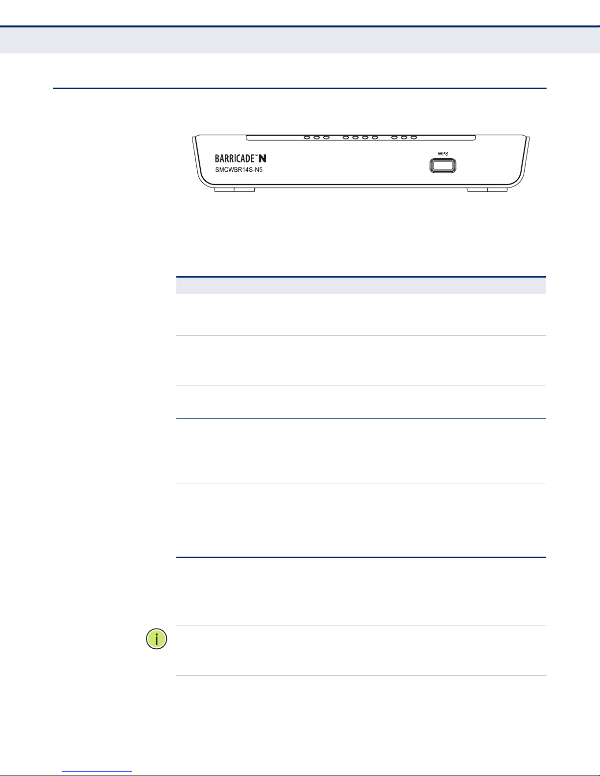
FRONT PANEL
Figure 1: Front Panel
C
HAPTER
1
| Introduction
Front Panel
LED INDICATORS The
table.
Table 2: LED Behavior
LED Status Description
Power On The unit is receiving power and is operating normally.
System On The Router is initializing or may have a system error.
WLAN On/Blinking The Wireless function is enabled.
WAN
LAN (1-4)
WPS On A wireless device has been successfully added to the
Router
includes ten status LED indicators, as described in the following
Off There is no power currently being supplied to the
Blinking The Router is working properly.
Off The Router has a system error.
Off The Wireless function is disabled.
On There is a device linked to the corresponding port, but
Blinking There is an active device linked to the corresponding
Off There is no device linked to the corresponding port.
unit.
there is no activity.
port.
network by WPS. The LED will remain on for about 5
minutes.
WPS BUTTON Push this button to start WPS authentication of a wireless device. Push and
hold down this button for more than 5 seconds to reset the unit.
N
OTE
LED will remain on for about 5 minutes and then turn off. When press and
hold the WPS Button for more than 5 seconds, you will reset the router.
Slow Blinking A wireless device is connecting to the network by
Off WPS is not in progress.
:
After a device is successfully added to the network by WPS, the WPS
– 26 –
WPS. This process lasts for about 2 minutes.
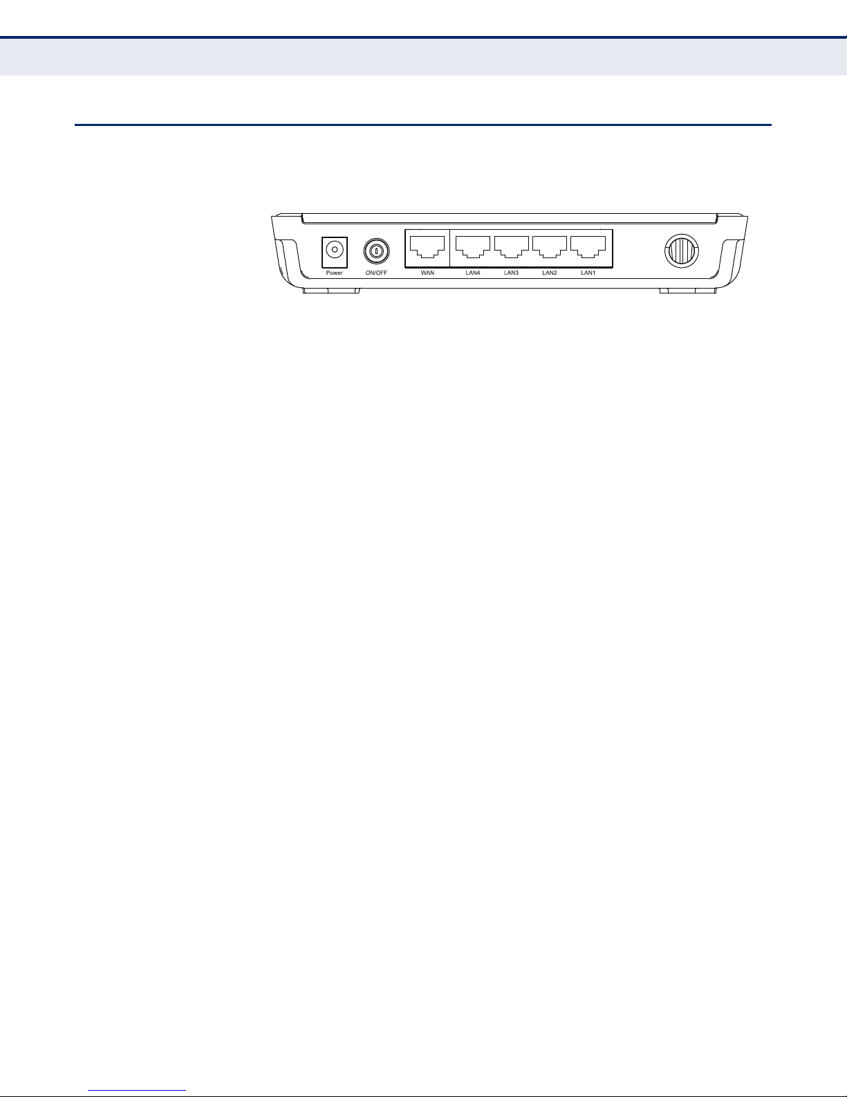
REAR PANEL
Figure 2: Rear Panel
The following items are located on the rear panel (from left to right).
WIRELESS ANTENNAS Receives and transmits wireless data.
C
HAPTER
1
| Introduction
Rear Panel
POWER The Power socket is where you connect the power adapter. Use the power
adapter provided with the Router.
ETHERNET WAN PORT This WAN port is where you connect the DSL/cable Modem.
ETHERNET LAN
LAN1,2,3,4: These ports (1, 2, 3, 4) connect the Router to local PCs.
PORTS
– 27 –

2 CONNECTING THE ROUTER
SYSTEM REQUIREMENTS
You must meet the following minimum requirements:
◆ Broadband Internet Access Service (DSL/Cable/Ethernet)
◆ One DSL/Cable Modem that has an RJ-45 connector.
◆ PCs with working Ethernet adapters and Ethernet cables with RJ-45
connectors.
◆ TCP/IP protocol on each PC.
◆ Web browser, such as Microsoft Internet Explorer, Mozilla Firefox, or
Apple Safari.
INSTALLATION ENVIRONMENT REQUIREMENTS
◆ Place the Router in a well ventilated place far from any heater or
heating vent
◆ Avoid direct exposure to any strong light (such as sunlight)
◆ Keep at least 2 inches (5 cm) of clear space around the Router
◆ Operating Temperature: 0 °C ~ 40 °C (32 °F ~ 104 °F)
◆ Operating Humidity: 10% ~ 90% RH, Non-condensing
CONNECTING THE ROUTER
Before installing the Router, make sure your PC is successfullyconnected to
the Internet through the broadband service. If there are any problems,
first contact your ISP. After that, install the Router according to the
following steps.
1. Power off your PC, Cable/DSL Modem, and the Router.
2. Locate an optimum location for the Router. The best place is usually at
the center of your network. The place must meet the Installation
Environment Requirements.
– 28 –
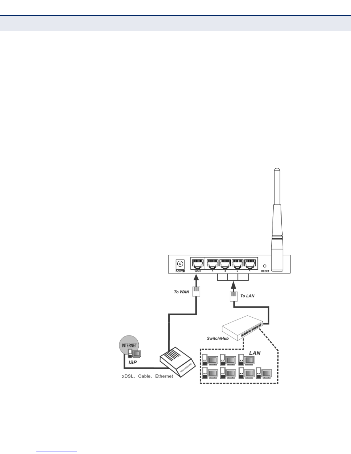
C
HAPTER
2
| Connecting the Router
Connecting the Router
3. Adjust the direction of the antennas. Normally, upright is the best
direction.
4. Connect PCs and any switch in your LAN to the LAN Ports on the Router,
as shown in Figure 3.
5. Connect the DSL/Cable Modem to the WAN port on the Router, as
shown in Figure 3.
6. Connect the AC power adapter to the power socket on the Router, and
the other end into an electrical outlet. The Router will start to work
automatically.
7. Power on your PC and Cable/DSL Modem.
Figure 3: Hardware Installation
– 29 –

3 QUICK INSTALLATION GUIDE
This chapter shows you how to quickly configure the basic functions of your
Router using the Quick Setup Wizard.
TCP/IP CONFIGURATION
The default IP address of the Router is 192.168.2.1. And the default
Subnet Mask is 255.255.255.0. These values can be changed as you
desire. In this guide, all the default values are used for descriptions.
Connect local PCs to the LAN ports of the Router. And then you can
configure the IP address for your PC in the following two ways.
CONFIGURE THE IP ADDRESS MANUALLY
1. Set up the TCP/IP Protocol for your PC. If you need instructions on how
to do this, refer to Appendix B: “Configuring the PC” on page 114.
2. Configure the network parameters. The IP address is 192.168.2.xxx
(“xxx” is any number from 2 to 254), Subnet Mask is 255.255.255.0,
and Gateway is 192.168.2.1 (the Router's default IP address).
OBTAIN AN IP ADDRESS AUTOMATICALLY
1. Set the TCP/IP Protocol to “Obtain an IP address automatically” mode
on your PC. If you need instructions as to how to do this, refer to
Appendix B: “Configuring the PC” on page 114.
2. Then the built-in DHCP server will assign IP address for the PC.
Now you can run the Ping command at the command prompt to verify the
network connection between your PC and the Router. The following
example is for Windows 2000.
Open a command prompt and type “ping 192.168.2.1”, and then press
Enter.
If the result displayed is similar to the Figure 4 on page 31, it means a
connection between your PC and the Router has been established.
– 30 –
 Loading...