


Barricade Plus
VPN IPSEC & PPTP
Configuration Guide
The Information in this guide applies to the:
● Barricade™ Plus Cable/DSL Broadband Router (SMC7004FW)
● Barricade™ Plus Wireless Cable/DSL Broadband Router (SMC7004WFW)
NEXT – Table of Contents

BACK - Introduction
NEXT – Installing VPN Protocols
This document will guide you through configuring and implementing secure, remote
connections to your LAN using the VPN functionality of your Barricade Plus Cable/DSL
Broadband Router.
This document is divided into the following sections:
1. Installing Virtual Private Network Protocols
❍ Windows 95/98/98SE
❍ Windows Me
❍ Windows NT
❍ Windows 2000/XP
2. Configuring your MS PPTP Client to Connect to the Barricade Plus
3. Configuring your Barricade Plus as a PPTP Client
4. Configuring your Barricade Plus as a PPTP Server
5. Barricade Plus IPSec Tunnel Configuration
6. Glossary

BACK - Table of Contents
NEXT – Windows 95/98/98SE
SECTION 1: Installing VPN Protocols
This section outlines the process for installing the necessary VPN protocols on the
following operating systems:
§
Windows 95/98/98SE
§
Windows Me
§
Windows NT
§
Windows 2000/XP
Before you begin this configuration process please verify that you have the following:
§
Original (Licensed) Windows CD
BACK - Installing VPN Protocols
NEXT – Windows Me
Windows 95/98/98SE
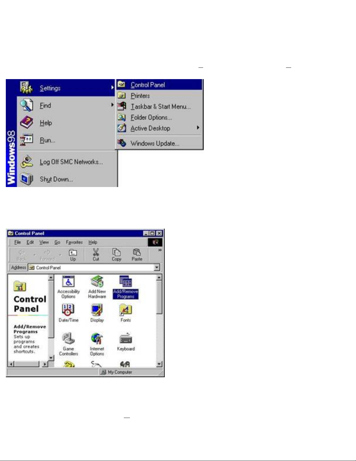
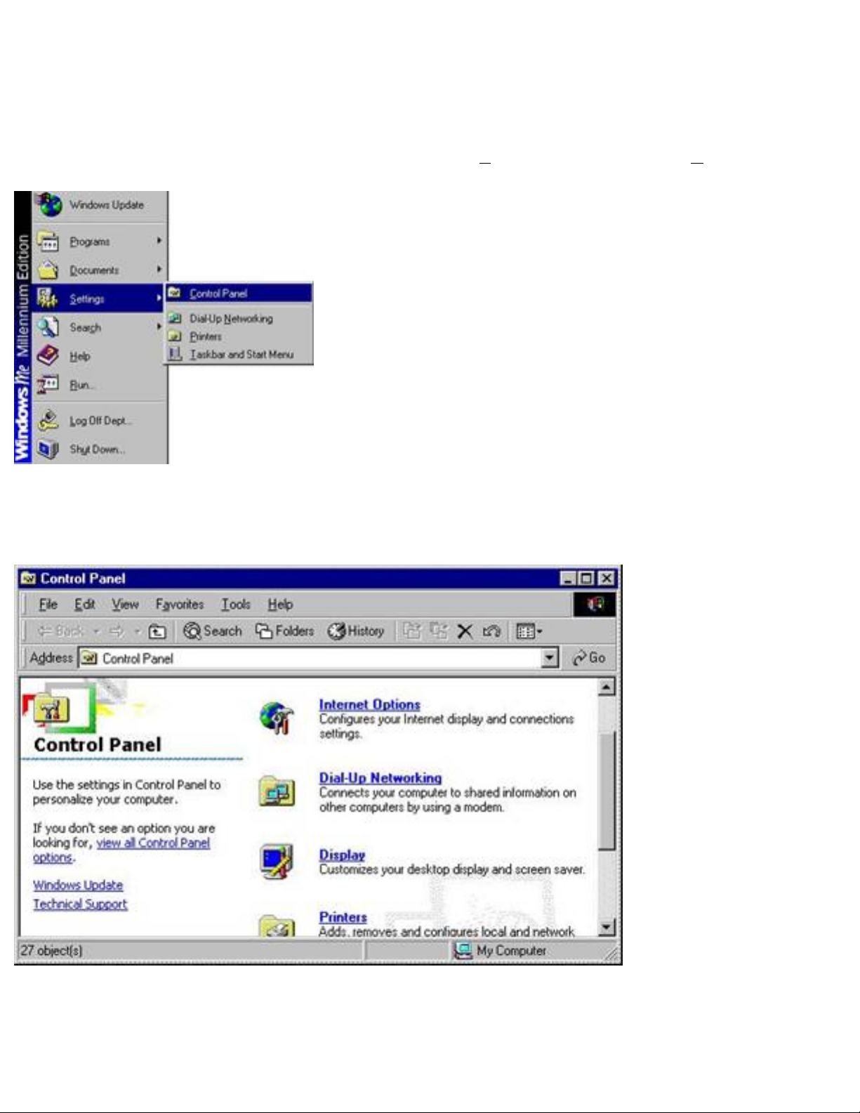
Step 1: Click on the [Start] button, then choose [Settings], then select [Control Panel].
Figure 1.0
Step 2: Locate and double-click the [Add/Remove Programs] icon.
Figure 1.1
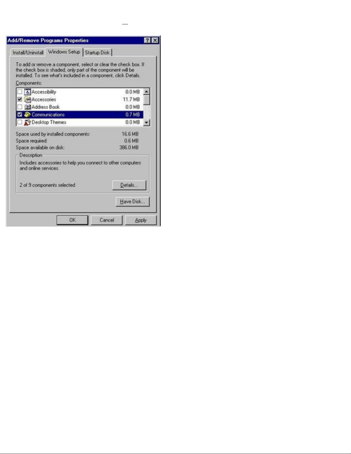
Step 3: Click on the [Windows Setup] tab and highlight the [Communication]
component, then click on the [Details…] button.
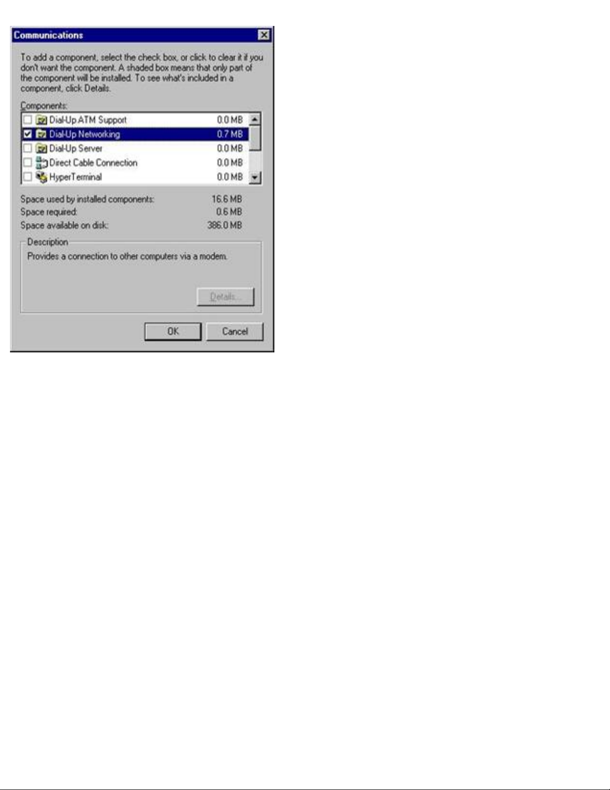
Figure 1.2
Step 4: In the [Communication] dialog box, verify that the following 2 options are
selected:
§
[Dial-Up Networking]
§ [Virtual Private Networking]
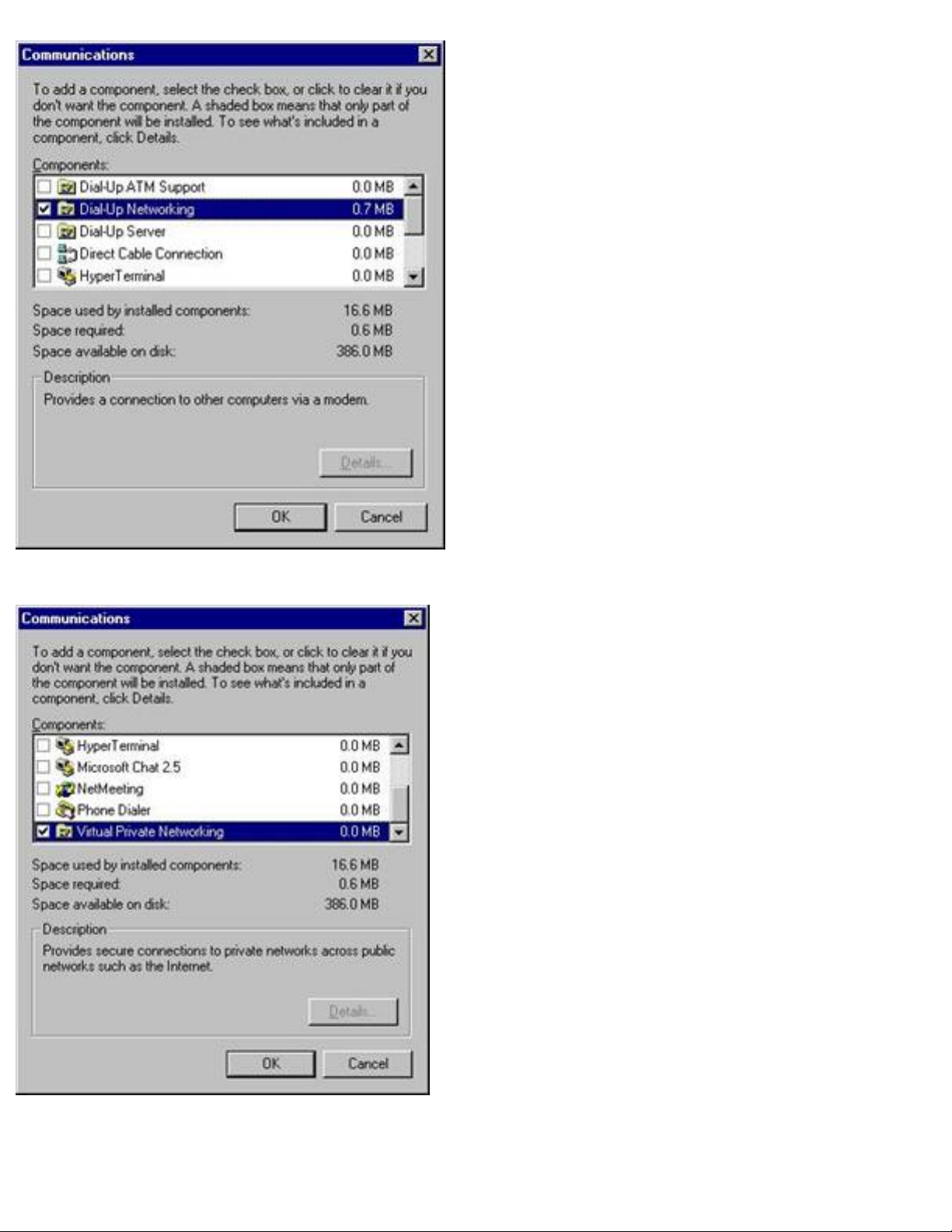
Figure 1.3
Figure 1.4
When you have verified or selected these 2 options, click the [OK] button to save the

settings and close the [Communications] dialog box.
If you already had these options selected, click the [Cancel] button to close the
[Communications] dialog box, then click the [Cancel] button again to close the [Add /
Remove Programs] dialog box. Skip to Section 2!
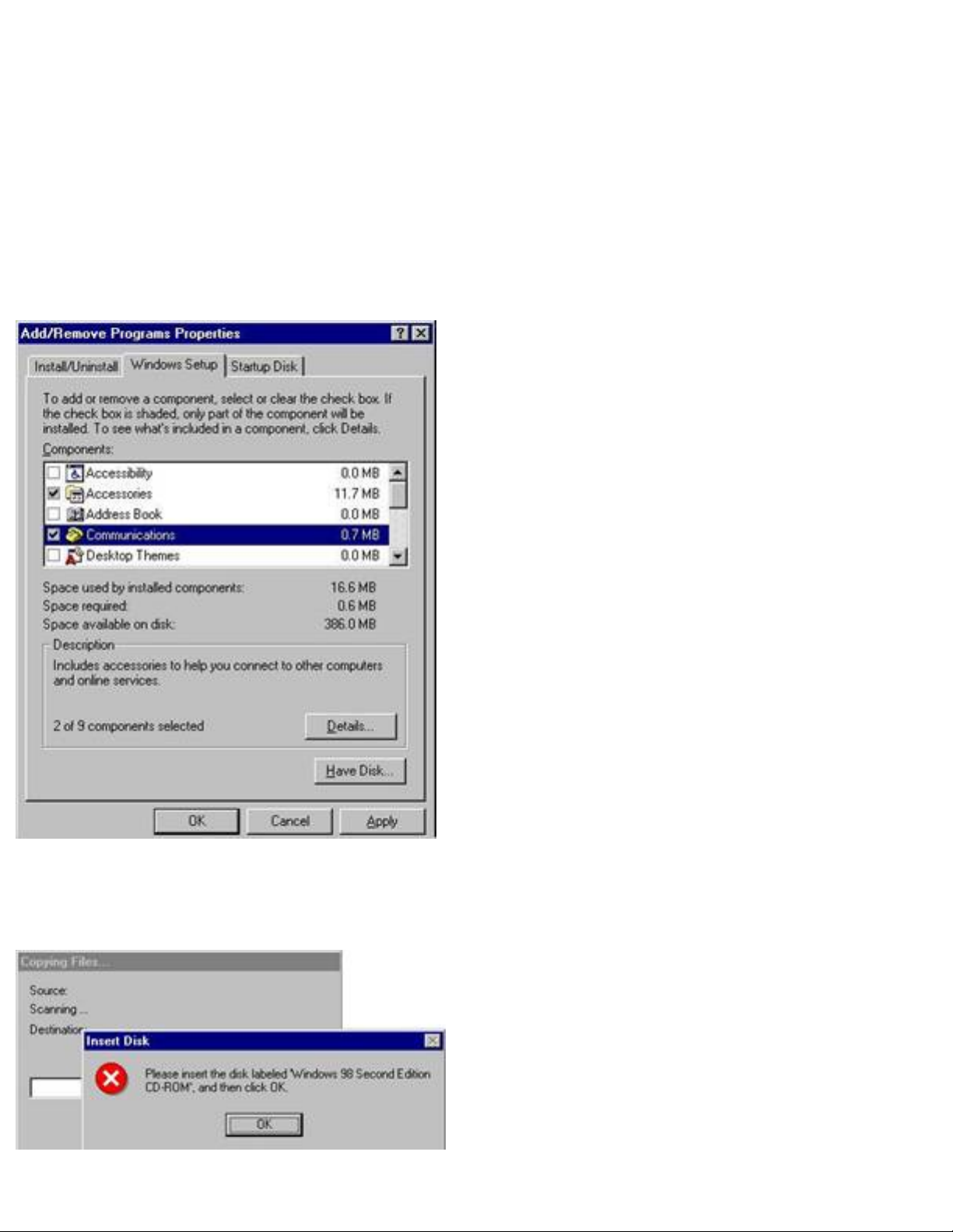
Step 5: The [Communications] option should now be checked. Click the [OK] button to
save this change and close the [Add/Remove Programs] dialog box.
Figure 1.5
Step 6: If prompted, please insert your [Windows CD] to copy the required system files.
Figure 1.6
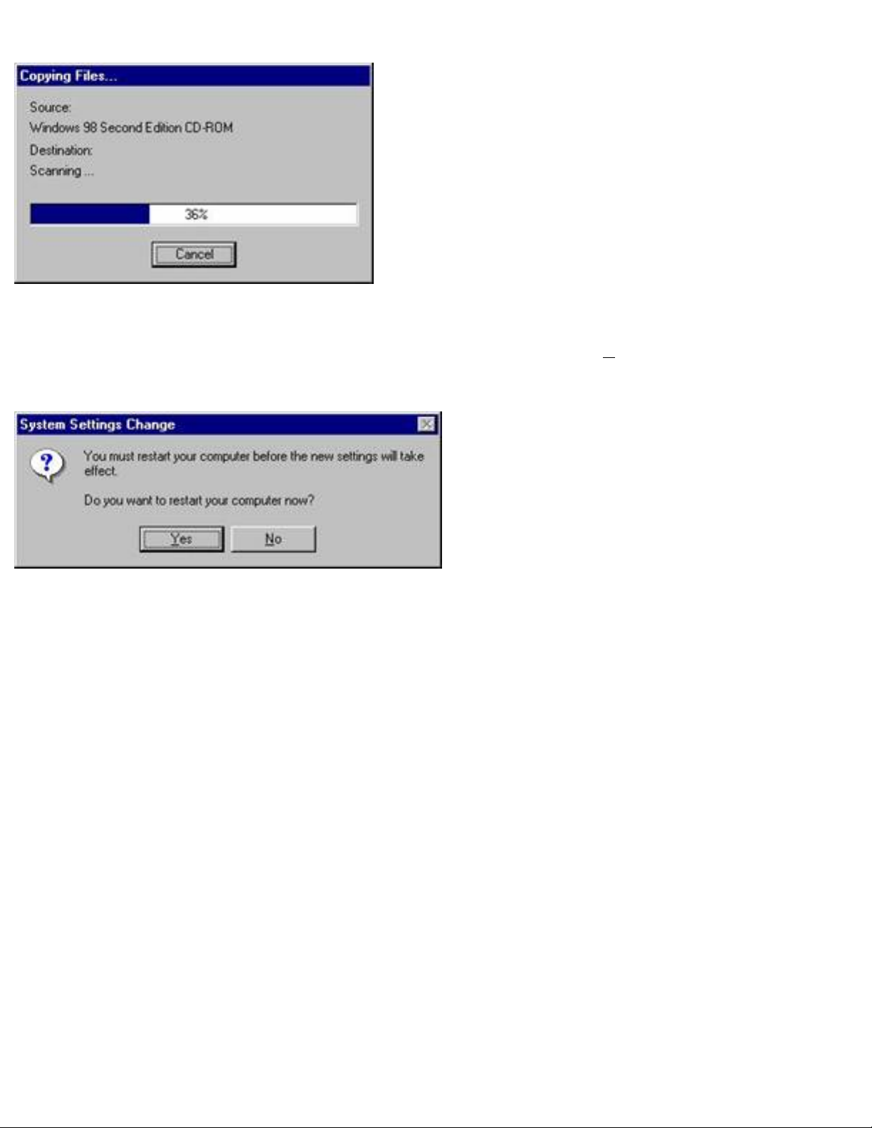
Figure 1.7
Step 7: When prompted with the dialog box below, click the [Yes] button to reboot your
computer and complete the installation process.
Figure 1.8
BACK – Windows 95/98/98SE
NEXT – Windows NT
Windows Me
Step 1: Click on the [Start] button, then choose [Settings], then select [Control Panel]
Figure 1.0
Step 2: Locate and double-click the [Dial-Up Networking] icon.
Figure 1.1
Step 3: Click on the [Windows Setup] tab and highlight the [Communication]
component, then click on the [Details…] button.
Figure 1.2
Step 4: In the [Communication] dialog box, verify that the following 2 options are
selected:
§ [Dial-Up Networking]
[Virtual Private Networking]
§
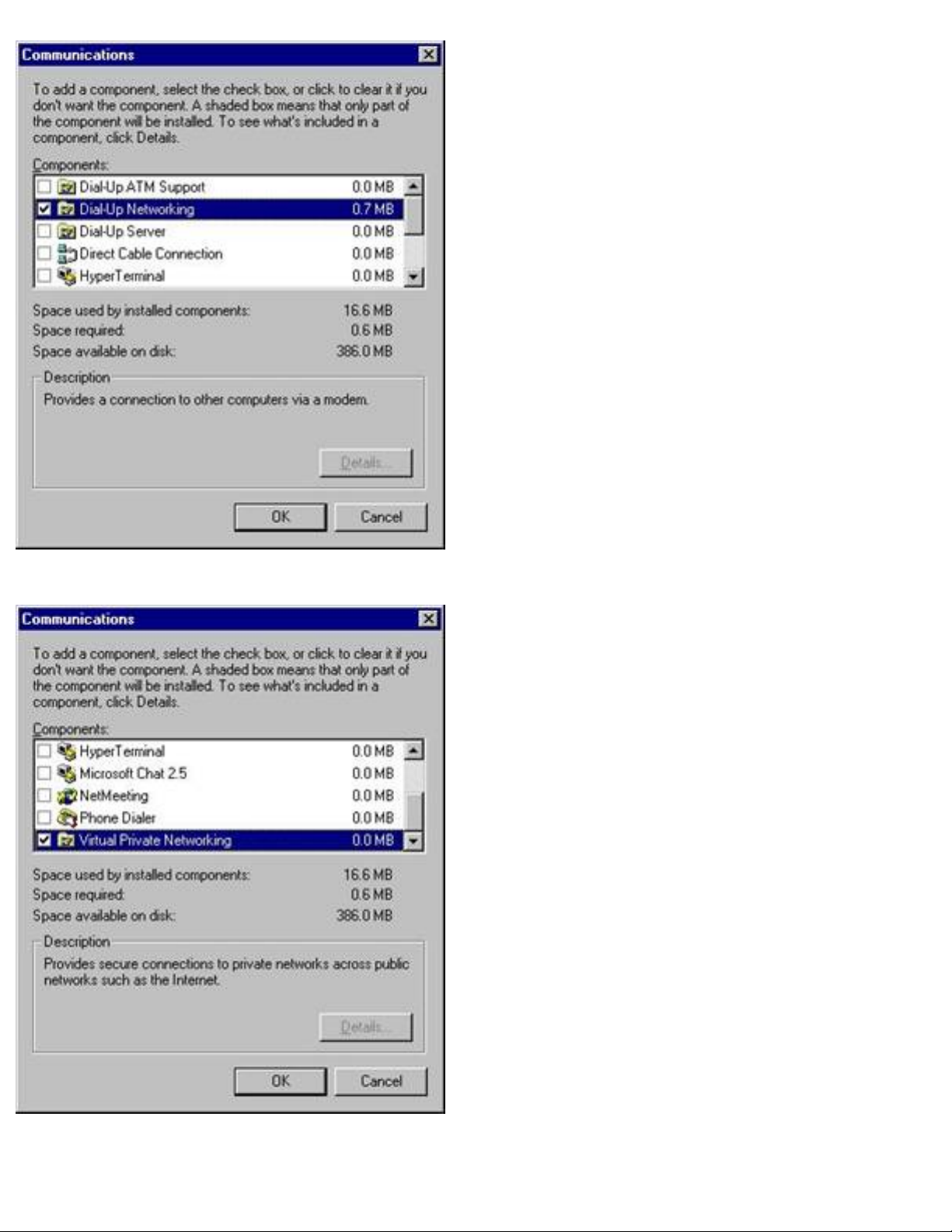
Figure 1.3
Figure 1.4
When you have verified or selected these 2 options, click the [OK] button to save the
settings and close the [Communications] dialog box.
If you already had these options selected, click the [Cancel] button to close the
[Communications] dialog box, then click the [Cancel] button again to close the [Add /
Remove Programs] dialog box. Skip to Section 2!
Step 5: The [Communications] option should now be checked. Click the [OK] button to
save this change and close the [Add/Remove Programs] dialog box.
Figure 1.5
Step 6: If prompted, please insert your [Windows CD] to copy the required system files.
Figure 1.6
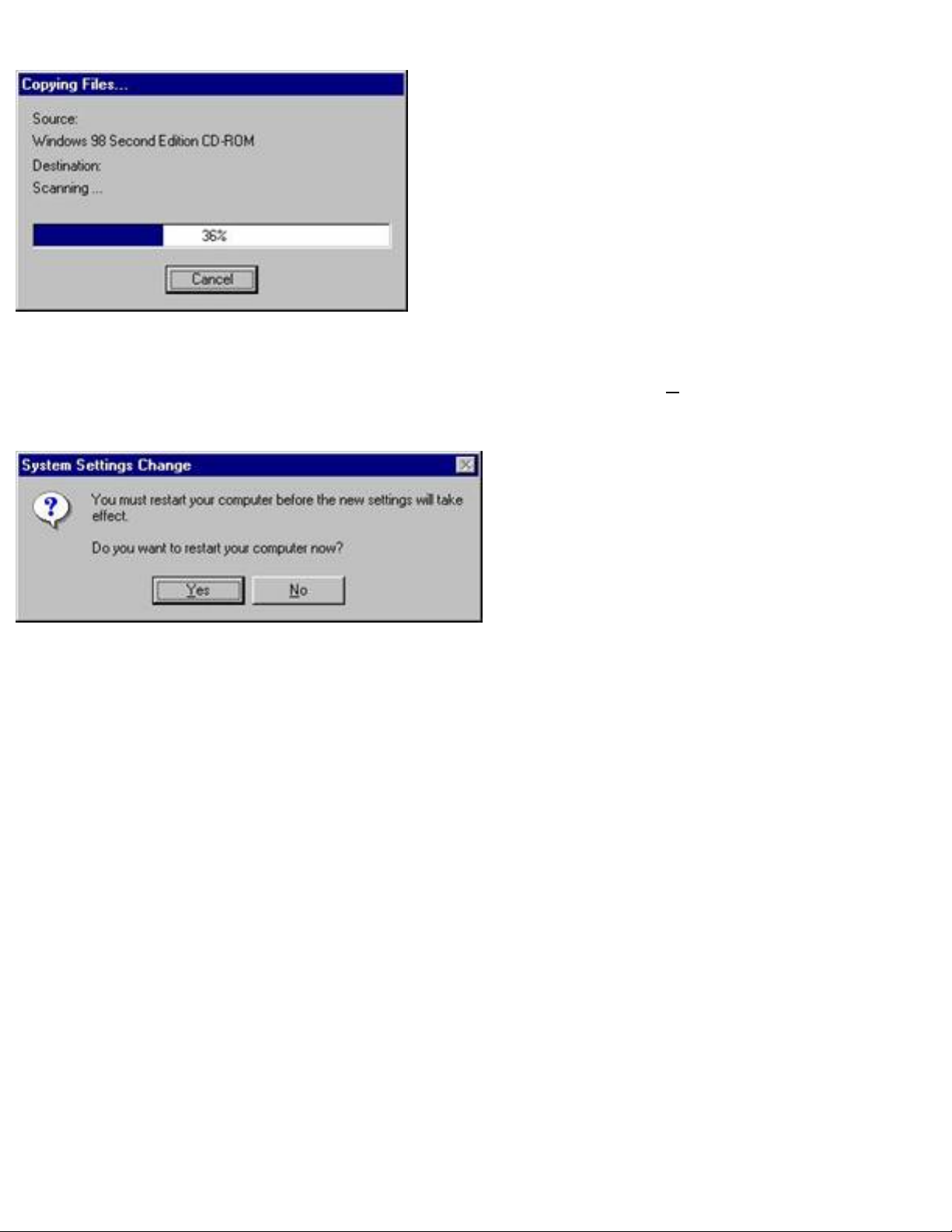
Figure 1.7
Step 7: When prompted with the dialog box below, click the [Yes] button to reboot
your computer and complete the installation process.
Figure 1.8
BACK – Windows Me
NEXT – Windows 2000/XP
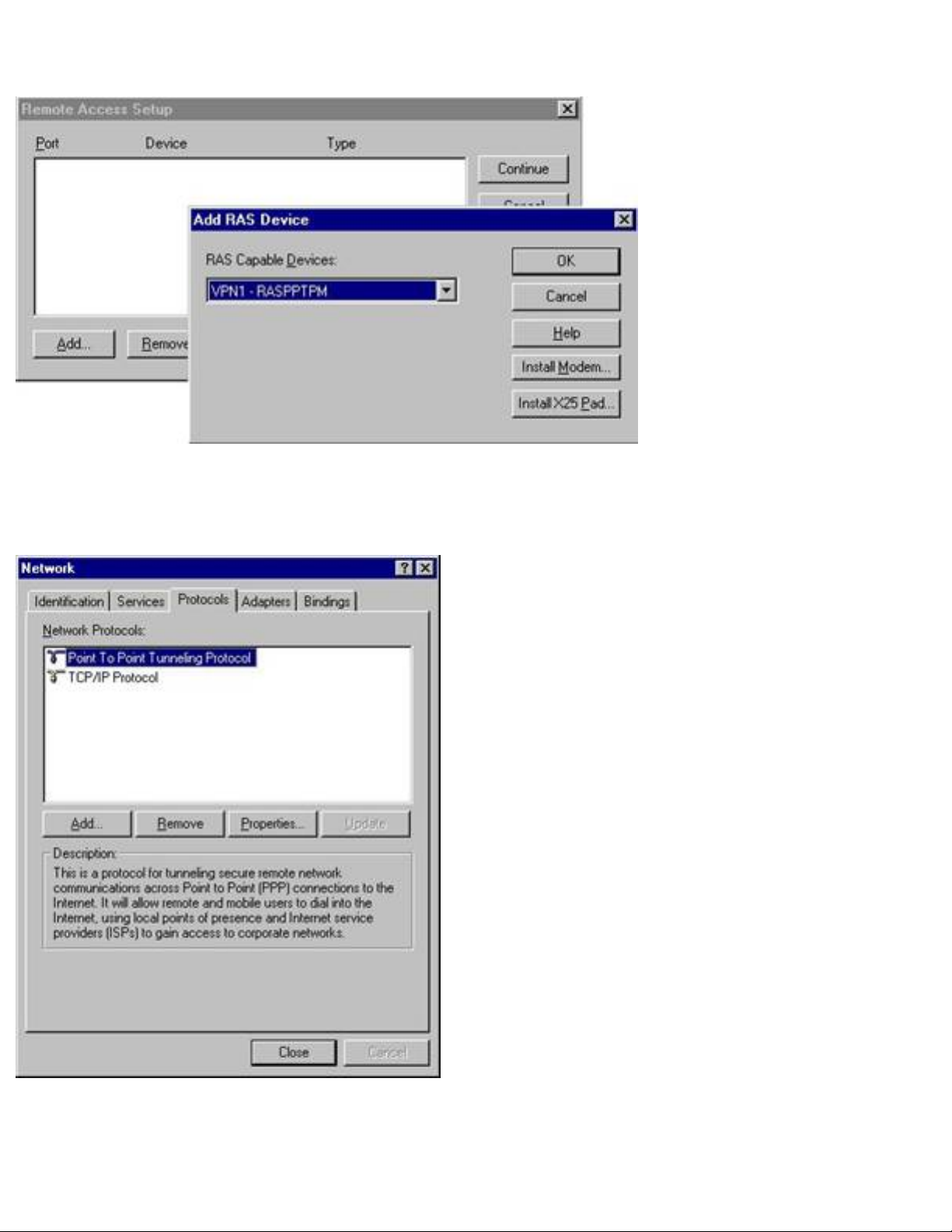
Windows NT
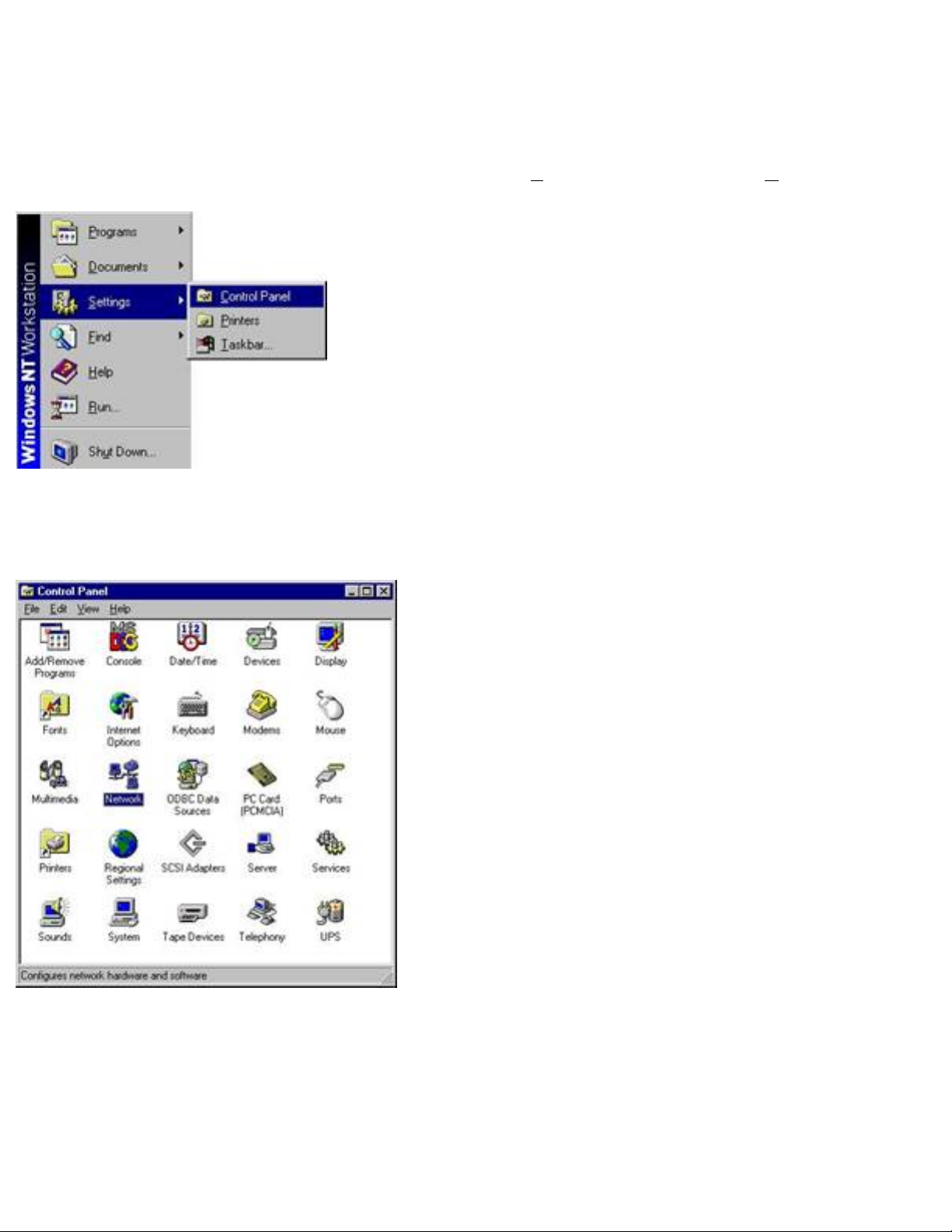
Step 1: Click on the [Start] button, then choose [Settings], then select [Control Panel]
Figure 1.0
Step 2: Double-click [Network].
Figure 1.1
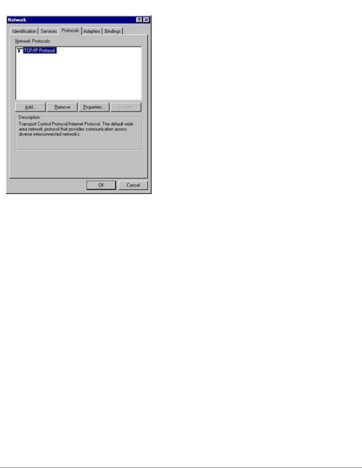
Figure 1.2
Step 3: On the [Protocols] tab, click [Add] and select [Point-to-Point Tunneling
Protocol]. Then press [OK].
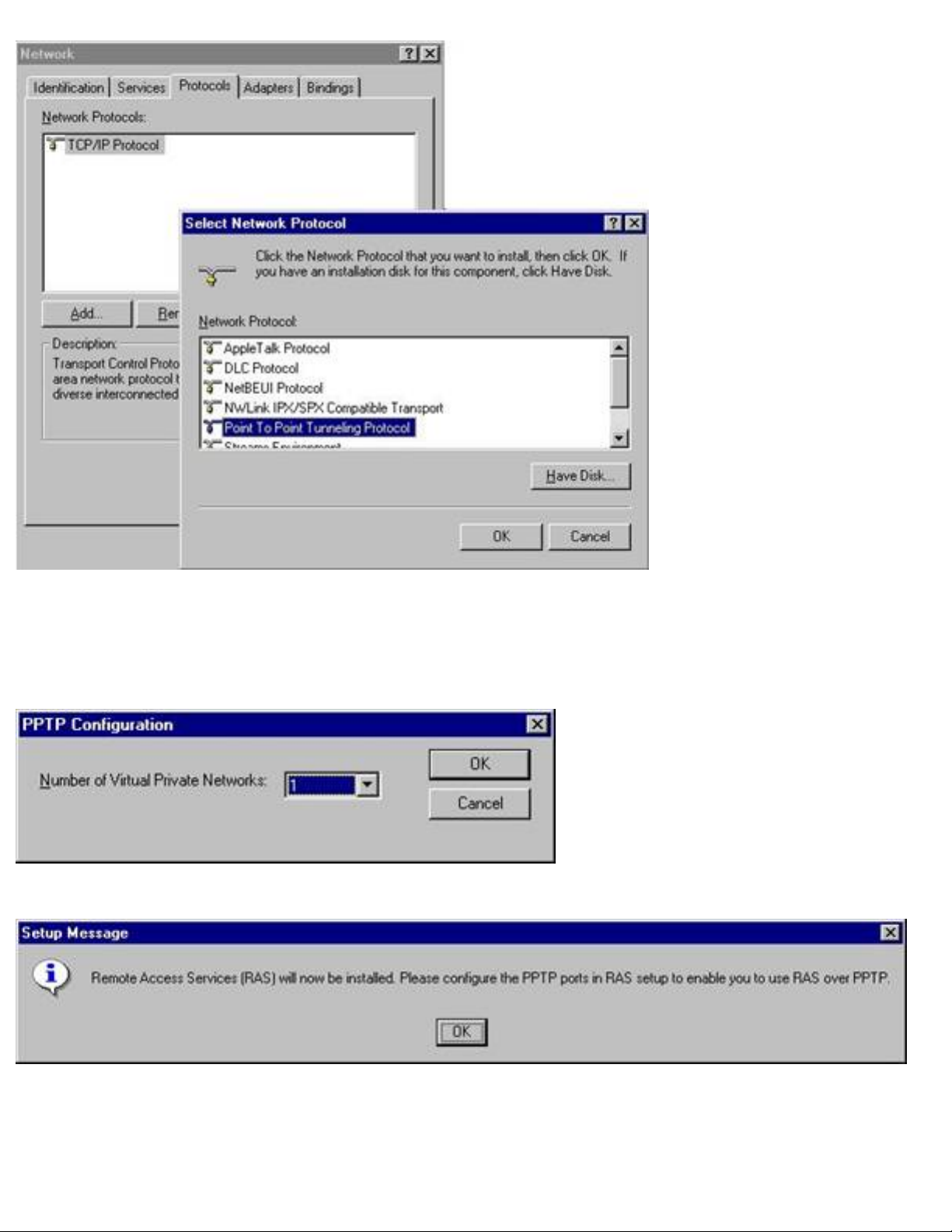
Figure 1.3
Step 4: After the protocol is installed, Remote Access Service (RAS) will initialize. You
must add at least one VPN port as a port in the RAS setup interface.
Figure 1.4
Figure 1.5
Step 5: At this time, specify which protocols you want to run for that VPN port. You can
install up to 256 VPN ports. Each VPN can be connected to a network. Make sure that at
least one VPN is configured for dial-out.
Figure 1.6
Step 6: Press [Close] and restart the machine when requested to do so.
Figure 1.7

BACK - Windows NT
NEXT – Configuring the PPTP Client
Windows 2000/XP
Windows 2000 and Windows XP already have the required VPN communication
components installed. Please verify that you can connect to the Internet either through a
dial-up connection or through a LAN.
If you can connect to the Internet, please go to the Section 2.

BACK - Windows 2000/XP NEXT – Windows 95/98/98SE
SECTION 2: Configuring your MS PPTP Client
This section outlines the process for configuring a PPTP client on the following operating
systems:
§
Windows 95/98/98SE
§
Windows Me
§
Windows NT
§
Windows 2000
§
Windows XP
Before you begin this configuration process please verify that you have the following:
§
IP Address of the Barricade Plus Router you are connecting to

BACK - Configuring the PPTP Client
NEXT – Windows Me
Windows 95/98/98SE
Step 1: Double-click the [My Computer] icon on your Desktop.
Step 2: In the [My Computer] window, locate and double-click the [Dial-Up Networking]
icon to launch the [Welcome to Dial-Up Networking] wizard
Figure 1.0
NOTE: If the network wizard does not prompt you, locate and click on the [Make a New
Connection] icon to launch it.
Step 3: Click [Next >] to start the Wizard

Figure 1.1
Step 4: In the dialog box show below:
§
Enter a name for this VPN connection and
§ Verify that you have the [Microsoft VPN Adapter] selected under the [Select a
device:] drop down menu
Then click the [Next >] button to continue.
Figure 1.2
Step 5: In the [Host name or IP Address:] text box, enter the WAN IP address of the

Barricade Plus that you are connecting to and then click the [Next] button to continue.
Figure 1.3
Step 6: Once you have completed the [Make New Connection] wizard, click the [Finish]
button to save this configuration.
Step 7: Double-click the [My Computer] icon on your Desktop.
Step 8: Locate and double-click the [Dial-Up Networking] icon.
Figure 1.4
Step 9: In the [Dial-Up Networking] window you will see the new VPN connection that

you created. To access this connection, double-click the connection icon.
Figure 1.5
Step 10: When prompted with the [Connect To] dialog box shown below, please
provide and verify the following information:
§
Username
§ Password
§ The [VPN server:] text box has WAN IP address of the Barricade Plus you are
connecting to
To connect to the Barricade Plus VPN server, click the [Connect] button to initialize the
VPN connection.

Figure 1.6
Step 11: To verify your VPN connection, locate and double-click the connection icon
that is displayed in the system tray.
Once you are connected you should see two new monitor icons in the system tray, and
you will be able to access the computers on the remote network as if they were on your
local LAN. You can double-click on the two linked monitors to view properties of the VPN
tunnel.
Figure 1.7

BACK - Windows 95/98/98SE
NEXT – Windows NT
Windows Me
Step 1: Double-click the [My Computer] icon on your desktop and then click the [Dial-
Up Networking] link on the bottom left hand corner of the window.
Figure 1.0
Step 2: A Welcome window should appear. Click [Next >] to continue.
Figure 1.1
Step 3: If this is your first time configuring a VPN session, you will be asked to enter
your area code. Please do so and press [Close] to continue.

Figure 1.2
Step 4: Enter a name for the VPN connection you wish to establish and click [Next >].
(i.e. – Barricade VPN)
Figure 1.3
Step 5: Enter the WAN IP address of the Barricade Plus you wish to connect to and click
[Next >].

Figure 1.4
Step 6: You have completed the VPN client setup. Click [Finish] to exit.
Step 7: Go back into [My Computer] and click on the [Dial-Up Networking] link again.
You should now see the new VPN connection that you just configured. Go ahead and
double-click on the name of the connection.
Figure 1.5
Step 8: Enter the username and password that the Administrator of the remote network
has given you. Verify that the VPN Server field has the correct WAN IP address. Then
press the [Connect] button. (Note: Be sure to enter this correctly as you will NOT be
able to connect without the correct login data)
Once you are connected you should see two new monitor icons in the system tray, and
you will be able to access the computers on the remote network as if they were on your
local LAN. You can double-click on the two linked monitors to view properties of the VPN

tunnel.
Figure 1.6
Figure 1.7

BACK - Windows Me
NEXT – Windows 2000
Windows NT
Step 1: Double-click on the [My Computer] icon on your Desktop. Then double-click the
[Dial-up Networking] icon.
Figure 1.0
Step 2: If this is your first time configuring a VPN session, you will be asked to enter
your area code. Please do so and press [Close] to continue.
Figure 1.1

Step 3: You will also be asked to make an entry in the Phonebook. Press [OK] to
continue.
Figure 1.2
Step 4: Enter a name for this entry and click the [Next >] button. (i.e. – Barricade VPN)
Figure 1.3
Step 5: Enter the WAN IP Address of the Barricade Plus that you are connecting to and
click [Next >]

Figure 1.4
Step 6: Press [Finish] to exit the wizard.
Figure 1.5
Step 7: Now you can review the settings you configured and choose to [Dial] the PPTP
Server. The [Phone number preview:] section should show the WAN IP address of the
Barricade Plus you are connecting to. Press [Dial] to continue and connect.

Figure 1.6
Step 8: Enter the username and password that the Administrator of the remote network
has given you. Verify that the VPN Server field has the correct WAN IP address. Then
press the [OK] button. (Note: Be sure to enter this correctly as you will NOT be able to
connect without the correct login data)
Figure 1.7
Once you are connected you should see two new monitor icons in the system tray, and
you will be able to access the computers on the remote network as if they were on your
local LAN. You can double-click on the two linked monitors to view properties of the VPN
tunnel.

Figure 1.8

BACK - Windows NT
NEXT – Windows XP
Windows 2000
Step 1: Right-click the [My Network Places] icon on your desktop and click [Properties].
Figure 1.0
Step 2: Double-click [Make New Connection].
Figure 1.1
Step 3: If this is your first time configuring a VPN session, you may be asked to enter

your area code. Please do so and press [OK] to continue.
Figure 1.2
Step 4: A wizard will appear. Please click [Next >] to continue.
Figure 1.3

Step 5: Select the [Connect to a private network through the Internet] option and click
[Next >].
Figure 1.4
Step 6: Enter the WAN IP address of the Barricade Plus that you wish to establish a
connection with. Then click [Next >].
Figure 1.5

Step 7: If you would like to give other users access to this VPN, select [For all users].
Otherwise, select [Only for myself] and click [Next >] to continue.
Figure 1.6
Step 8: You have completed the VPN client setup. Click [Finish] to exit.
Step 9: Enter the username and password that the Administrator of the remote network
has given you. Verify that the VPN Server field has the correct WAN IP address. Then
press the [Connect] button. (Note: Be sure to enter this correctly as you will NOT be
able to connect without the correct login data)

Figure 1.7
Once you are connected you should see two new monitor icons in the system tray, and
you will be able to access the computers on the remote network as if they were on your
local LAN. You can double-click on the two linked monitors to view properties of the VPN
tunnel.
Figure 1.8

Figure 1.9

BACK - Windows 2000
Windows XP
Step 1: Go into the Control Panel.
NEXT – Barricade Plus PPTP Client
Figure 1.0
Step 2: Click the [Network and Internet Connections] link.
Figure 1.1
Step 3: Click the [Create a connection to the network at your workplace] link.

Figure 1.2
Step 4: Select the [Virtual Private Network connection] option and click [Next >] to
continue.
Figure 1.3
Step 5: Enter a name for the VPN connection you wish to establish and click [Next >].
(i.e. – Barricade VPN)

Figure 1.4
Step 6: Enter the WAN IP address of the Barricade Plus that you wish to establish a
connection with. Then click [Next >].

Figure 1.5
Step 7: You have completed the VPN client setup. Click [Finish] to exit.
Step 8: Go back into the [Network and Internet Connections] (see Step 2) window and
click the [Network Connections] link.
Figure 1.6
Step 9: You should now see the new VPN connection that you just created. Double-click
on this connection.
Figure 1.7
Step 10: Enter the username and password that the Administrator of the remote
network has given you. Verify that the VPN Server field has the correct WAN IP address.
Then press the [Connect] button. (Note: Be sure to enter this correctly as you will NOT
be able to connect without the correct login data)
Once you are connected you should see two new monitor icons in the system tray, and

you will be able to access the computers on the remote network as if they were on your
local LAN. You can double-click on the two linked monitors to view properties of the VPN
tunnel.
Figure 1.8
Figure 1.9

BACK - Windows XP
NEXT – Barricade Plus PPTP Server
SECTION 3: Configuring the Barricade Plus as a PPTP Client
IMPORTANT NOTE: When setting up a VPN connection, your local LAN and the remote
network must be on different subnets (i.e. – If the remote gateway/router has a LAN IP
of 192.168.1.1, your Barricade Plus should be set to 192.168.x.1 where X is equal to a
number between 2 and 254)
Step 1: Open up your web browser and type in the IP Address of your Barricade Plus.
Step 2: Enter your password to log into the router and then go into the Advanced
Setup.
Step 3: Click on the link for VPN on the left. Then click PPTP.
Step 4: The router allows you to configure up to 20 different PPTP VPN accounts. Click
the [Edit] link for the first account and then you will be able to configure the appropriate
IP Addresses.
Figure 1.0
Step 5: Enter the necessary data. This information is used to establish a Point-to-Point

Tunnel from the Barricade Plus to another Barricade Plus or a Windows-based PPTP
Server.
Figure 1.1
User name: Used by the server to identify the PPTP Client
Password: Used by the server to authorize the PPTP Client’s request for a Tunnel
Idle Time Out: When there is no activity for this amount of Idle Time, the Tunnel will be
broken
IP: Enter the LAN subnet of the remote network you are connecting to. (i.e. – If the IP’s
of clients on the remote network are 192.168.123.xxx, type in 192.168.123.0. The last
octet must always be zero because the PPTP Client is connecting to the entire LAN
subnet.)
Subnet Mask: Enter the subnet mask used on the remote network (i.e. – 255.255.255.0)
Gateway IP: Enter the WAN IP of the remote network (i.e. – 24.106.10.54). The last
octet should not be zero in this case. Enter the full WAN IP address.
Client Setting –
PPTP Client: Check this box to enable the Barricade’s PPTP Client
Host: Check this box only if you are connecting to a Windows-based PPTP server (Figure
1.1 shows Host as checked. Leave this unchecked if you are simply connecting to
another Barricade Plus or another VPN gateway)
Auto Reconnect: Check this box if you would like the PPTP Tunnel to be automatically reestablished if the connection is broken

Step 6: Once all the required fields have been filled in, press the [OK] button to
continue. Then check the [Accept to Connect] box.
Step 7: Scroll down to the section labeled [IP Address Pool]. Change the IP scheme to
match that of the PPTP server's internal network. (i.e. – If the PPTP server's LAN is using
an IP scheme of 192.168.2.xxx, change the IP Pool to be 192.168.2.xxx –
192.168.2.xxx) Also make sure that this range does not conflict with the ranges of other
DHCP servers in the network.
Figure 1.2
Then press the [Apply] button and your settings will be saved.
Figure 1.3
Step 8: Now click the [Status] link on the left navigation bar and you should see a
[Connect] and [Disconnect] button pertaining to the PPTP Client under the GATEWAY
column.

Figure 1.4
Step 9: Press [Connect] and the router will begin to establish a connection using the
settings previously configured in the VPN | PPTP section. Once the connection is
established, the information will be displayed on the STATUS page and in the SECURITY
LOG as well.
Figure 1.5
Once you are connected you will be able to access the computers on the remote network
as if they were on your local LAN.

BACK - Barricade Plus PPTP Client
NEXT – Barricade Plus IPSec Tunnels
SECTION 4: Configuring the Barricade Plus as a PPTP Server
IMPORTANT NOTE: When setting up a VPN connection, your local LAN and the remote
network must be on different subnets (i.e. – If the remote gateway/router has a LAN IP
of 192.168.1.1, your Barricade Plus should be set to 192.168.x.1 where X is equal to a
number between 2 and 254)
Step 1: Open up your web browser and type in the IP Address of your Barricade Plus.
Step 2: Enter your password to log into the router and then go into the Advanced
Setup.
Step 3: Click on the link for VPN on the left. Then click PPTP.
Step 4: The router allows you to configure up to 20 different PPTP VPN accounts. Click
the [Edit] link for the first account and then you will be able to configure the appropriate
IP Addresses.
Figure 1.0
Step 5: Enter the necessary data. This information is used to establish a Point-to-Point

Tunnel from the Barricade Plus to another Barricade Plus or a Windows-based PPTP
Client.
Figure 1.1
User name: The name you want to use to identify a particular PPTP Client
Password: The password you wish to use to authorize a particular PPTP Client
Idle Time Out: When there is no activity for this amount of Idle Time, the Tunnel will be
broken
IP: Enter the LAN subnet of the remote network that will connect to this router. (i.e. – If
the IP’s of clients on the remote network are 192.168.123.xxx, type in 192.168.123.0.
The last octet must always be zero because the PPTP Client is connecting to the entire
LAN subnet.)
Subnet Mask: Enter the subnet mask used on the remote network (i.e. – 255.255.255.0)
Gateway IP: This value must be 0.0.0.0 when configuring the Barricade Plus as a PPTP
Server
Client Setting –
PPTP Client: Leave this box unchecked when configuring a PPTP Server
Host: Check this box only if you will be using a Windows-based PPTP client to connect to
the Barricade Plus PPTP Server (Figure 1.1 shows Host as unchecked. Leave this
unchecked if you plan to have Barricade Plus PPTP Clients connect to this server)
Auto Reconnect: Check this box if you would like the PPTP Tunnel to be automatically reestablished if the connection is broken

Step 6: Once all the required fields have been filled in, press the [OK] button to
continue. Then check the [Accept to Connect] box.
Step 7: Scroll down to the section labeled [IP Address Pool]. Change the IP scheme to
match that of the PPTP server's internal network. (i.e. – If the PPTP server's LAN is using
an IP scheme of 192.168.5.xxx, change the IP Pool to be 192.168.5.xxx –
192.168.5.xxx) Also make sure that this range does not conflict with the ranges of other
DHCP servers in the network.
Figure 1.2
Then press the [Apply] button and your settings will be saved.
Figure 1.3
Step 8: Now click the [Status] link on the left navigation bar and you should see
[Disconnect] button pertaining to the PPTP Server under the GATEWAY column.

Figure 1.4
Step 9: Press [Disconnect] and the Server will begin to terminate the PPTP VPN session.
Once the connection has been broken, the information will be displayed on the STATUS
page and in the SECURITY LOG as well. The PPTP Server should show that the Line is
[Disconnected].

BACK - Barricade Plus PPTP Server
NEXT – Glossary
SECTION 5: Barricade Plus IPSec Tunnel Configuration
IMPORTANT NOTE: When setting up a VPN connection, your local LAN and the remote
network must be on different subnets (i.e. – If the remote gateway/router has a LAN IP
of 192.168.1.1, your Barricade Plus should be set to 192.168.x.1 where X is equal to a
number between 2 and 254)
Step 1: Open up your web browser and type in the IP Address of your Barricade Plus.
Step 2: Enter your password to log into the router and then go into the Advanced
Setup.
Step 3: Click on the link for VPN on the left. Then click IPSec.
Step 4: The Barricade Plus supports a maximum of 3 IPSec tunnels. These tunnels can
be established to different gateways/routers simultaneously.
(For example: Four companies in different physical locations could connect their
networks using IPSec with four Barricade Plus routers at the front of each network. Each
individual router would simply have their 3 tunnels configured to connect to the other
three routers.)

Figure 1.0: Tunnel 1
SPI: Security Parameter Index – This value must be the same for the Local Tunnel and
the Remote Tunnel (i.e. – The Barricade Plus on the remote end must have the same
value for SPI)
Local IP Address: Enter the subnet of the local LAN. (i.e. – If your router’s LAN IP is
192.168.2.1, type in 192.168.2.0)
Subnet Mask: This will always be a Class C subnet mask. (255.255.255.0)
Remote IP Address: Enter the subnet of the remote LAN. (i.e. – If the LAN IP of the
remote router/gateway is 192.168.3.1, type in 192.168.3.0)
Subnet Mask: Enter the subnet mask of the remote LAN
Security Gateway: Enter the exact WAN IP of the remote network. (This must be a public
IP address such as 64.58.123.12)
Hash Algorithm –
MD5: Message-Digest 5 – A one-way hash algorithm that essentially verifies data
integrity
SHA1: Secure Hash Algorithm 1 – A cryptographic message digest algorithm used to
create digital signatures. It is slower than MD5, but more secure.
Encrypt Algorithm –
3DES: Triple Data Encryption Standard – Uses a cipher method which breaks data into
blocks before encrypting them. It is slower than DES, but more secure.
DES: Uses a 16-character key to encrypt data over the VPN.

Figure 1.1: Tunnel 2
Figure 1.2: Tunnel 3

Figure 1.3
The above image shows that the Barricade Plus has a LAN IP of 192.168.2.1 and it has
been configured to connect to three other Barricade Plus units. Note that each of the
remote Barricade Plus units have DIFFERENT LAN IP addresses. This is essential to the
successful establishment of the IPSec VPN.

BACK - Barricade Plus IPSec Tunnels
SECTION 6: Glossary
3DES
This is a cryptographic algorithm for repeated DES operations that have the effect of
increasing the security of the encrypted message.
AH
The Authentication Header is a traditional IP packet consists of an IP header and a
payload, which can consist of a TCP or UDP header and data. If the AH is used, it
immediately follows the IP header. At the end of the AH is the authentication data, which
is a digital signature for the packet. To authenticate users, AH can use MD5 or SHA1
DES
(Data Encryption Standard) This is a cryptographic encryption algorithm that is part of
many standards.
DHCP
(Dynamic Host Configuration Protocol) This protocol automatically configures the TCP/IP
settings of every computer on your home network.
DNS
DNS stands for Domain Name System, which allows Internet host computers to have a
domain name (such as www.smc.com) and one or more IP addresses (such as
192.34.45.8). A DNS server keeps a database of host computers and their respective
domain names and IP addresses, so that when a domain name is requested (as in typing
" www.smc.com" into your Internet browser), the user is sent to the proper IP address.
The DNS server address used by the computers on your home network is the location of
the DNS server your ISP has assigned.
ESP
Encapsulating Security Payload is the protocol that handles encryption of IP data at the
packet level. It uses symmetric or secret key, cryptographic algorithms like Data
Encryption Standard (DES), and triples DES to encrypt the payload.
IP Address
IP stands for Internet Protocol. An IP address consists of a series of four numbers
separated by periods, that identifies an single, unique Internet computer host. Example:
192.34.45.8.

IPSecurity
IPSec provides IP network-layer encryption. IPSec can support large encryption networks
(such as the Internet) by using digital certificates for device authentication. It works at
the Layer 3 and secures everything on the network.
LAN
This is a communications network that serves users within a confined geographical area.
It is made up of servers, workstations, a network operating system and a
communications link. Servers are high-speed machines that hold programs and data
shared by network users. The workstations (clients) are the users' personal computers,
which perform stand-alone processing and access the network servers as required.
Diskless and floppy-only workstations are sometimes used, which retrieve all software
and data from the server. Increasingly, "thin client" network computers (NCs) and
Windows terminals are also used. A printer can be attached locally to a workstation or to
a server and be shared by network users. Small LANs can allow certain workstations to
function as a server, allowing users access to data on another user's machine. These
peer-to-peer networks are often simpler to install and manage, but dedicated servers
provide better performance and can handle higher transaction volume. Multiple servers
are used in large networks.
The message transfer is managed by a transport protocol such as TCP/IP and NetBEUI.
The physical transmission of data is performed by the access method (Ethernet, Token
Ring, etc.), which is implemented in the network adapters that are plugged into the
machines. The actual communications path is the cable (twisted pair, coax, optical fiber)
that interconnects each network adapter.
L2TP
L2TP stands for Layer 2 Tunneling Protocol. It is an extension of the Point-to-Point
Tunneling Protocol and is also used to establish virtual private networks. It is sometimes
used in conjunction with IPSec to provide authentication.
NAT
(Network Address Translation) This process allows all of the computers on your home
network to use one IP address. The NAT capability of the Barricade, allows you to access
the Internet from any computer on your home network without having to purchase more
IP addresses from your ISP.
Network Address Translation can be used to give multiple users access to the Internet
with a single user account, or to map the local address for an IP server (such as Web or

FTP) to a public address. This secures your network from direct attack by hackers, and
provides more flexible management by allowing you to change internal IP addresses
without affecting outside access to your network. NAT must be enabled to provide multiuser access to the Internet or to use the Virtual Server function.
PPPoE
(Point-to-Point Protocol over Ethernet) Point-to-Point Protocol is a method of secure data
transmission originally created for dial-up connections. PPPoE is for Ethernet
connections.
PPTP
(Point-to-Point Tunneling Protocol) It provides a means for tunneling IP traffic in Layer 2.
For instance, it allows you to establish a connection to a corporate network and share
files or other data as if your machine were actually on that local network.
Router
In communications, a device that examines the destination address of a message and
selects the most effective route. A router receives physical layer signals from a network,
performs data link and network layer protocol processing, then sends the signals via an
appropriate data link and physical layer protocols to another network.
SHA1
The Secure Hash Algorithm is a cryptographic message digest algorithm used to create
digital signatures. It is slower than MD5, but more secure.
SNMP
Format used for network management data. Data is passed between SNMP agents
(processes that monitor activity in hubs, switches, etc.) and the workstation used to
oversee the network. SNMP uses Management Information Bases (MIBs), which are
databases that define what information is obtainable from a networked device and what
can be controlled (turned off, on, etc.).
SPI
Stateful Packet Inspection ensures that the data coming into your network was
requested by an end node computer on your LAN. The Barricade Plus examines the
incoming data and compares it to a database of trusted information. As traffic leaves the
network it is defined by certain characteristics. Incoming information is then compared to
these sets of characteristics. If the incoming data matches the predefined set of
characteristics the incoming traffic is allowed. If no match is found the incoming traffic is
discarded.

SPI
Security Parameter Index is a 32-bit value which, together with an IP address and
security protocol, uniquely identifies a particular security association. It is a number that
tells the packet recipient which security protocols the sender is using. This information
includes which algorithms and keys are being applied by the sending device. When using
IKE to establish the security associations, the SPI for each security association is a
pseudo-randomly derived number. Without IKE, the SPI is manually specified for each
security association.
Subnet Mask
A subnet mask, which may be a part of the TCP/IP information provided by your ISP, is a
set of four numbers configured like an IP address. It is used to create IP address
numbers used only within a particular network (as opposed to valid IP address numbers
recognized by the Internet.
TCP/IP
(Transmission Control Protocol/Internet Protocol) This is the standard protocol for data
transmission over the Internet.
TCP
(Transmission Control Protocol) TCP and UDP (User Datagram Protocol) are the two
transport protocols in TCP/IP. TCP ensures that a message is sent accurately and in its
entirety. However, for real-time voice and video, there is really no time or reason to
correct errors, and UDP is used instead.
UDP
(User Datagram Protocol) This is a protocol within the TCP/IP protocol suite that is used
in place of TCP when a reliable delivery is not required. For example, UDP is used for
real-time audio and video traffic where lost packets are simply ignored, because there is
no time to retransmit. If UDP is used and a reliable delivery is required, packet sequence
checking and error notification must be written into the applications.
VPN
(Virtual Private Network) A VPN actually exists within a public network. This consists of a
point-to-point tunnel through which users can send and receive data. The data packets
are encrypted to provide for a true private connection to the endpoint (i.e. - corporate
network). These packets cannot be decrypted without the correct encryption keys. Once
the VPN tunnel is established, the client machine is authenticated and registered on the
network. Given the proper privileges, it can then communicate directly with other

machines as if it were actually on that local network.
 Loading...