

Page 1

ADSL Bridge/Router
SMC7003ADSL
Read Me First
User’s Manual
Page 2

The product names found in this manual are used for identification
purposes only and may be trademarks and/or registered trademarks of
their respective companies.
Copyright 2001
All Rights Reserved. No part of this document may be reproduced by
any means without the express permission of the company.
The information contained in this document is believed to be accurate
in every respect. We, however, cannot assume responsibility for any
consequences resulting from the use thereof. Information contained
within this document is subject to change. Revision to this document,
or new additions to it, may be issued to incorporate such changes.
Revision Status:
Model number Rev. Date Change
SMC7003ADSL 1.0 February 2001 Preliminary
SMC7003ADSL (version 1.0)
Page 3

Introduction
Introduction
The SMC7003ADSL provides unrivaled asymmetric high-speed data transport over a
single copper pair. Its very rich feature set includes an easy to use Setup Wizard, DHCP
support, a firewall for network protection and VPN capabilities for reduced cost of remote
access communications.
PACKING LIST
1. SMC7003ADSL Bridge/Router
2. DSL Cable (RJ-11, green cable)
3. Ethernet Cable (RJ-45, yellow cable)
4. USB Cable (grey cable)
5. Power Cord
6. AC Power Adapter
7. CD with the GUI software and USB Drivers
8. User’s Manual
SMC7003ADSL (version 1.0) i
Page 4

Table of Contents
Table of contents
Introduction
Chapter 1 Product Description 1
1.1 Minimum PC Requirements 1
1.2 Physical Descriptions 1
1.3 Front Status Indicators 2
1.4 Rear Panel 3
1.5 Parameters From Service Provider 4
1.6 Default Settings 6
Chapter 2 Installation 7
2.1 Hardware Installation Procedures 7
2.1.1 Ethernet Connection 8
2.1.2 USB Connection 9
2.2 Connecting the PC to the SMC7003ADSL 10
2.2.1 Ethernet Connection 10
2.2.2 USB Installation 15
2.2.2.1 How to install the USB Driver 15
2.2.2.2 Configuring the PC for the USB 16
Chapter 3 Configuration 17
3.1 GUI Installation 17
3.2 Easy Setup Flow Chart 18
3.3 Login Screen 19
3.4 Bridge Mode Configuration 20
3.5 Router Mode Configuration 22
Chapter 4 Warranty and Shipping Information 25
4.1 Customer Service and Technical Support 25
4.2 SMC’s Limited Warranty 26
Appendix A FCC Notice 29
Appendix B Installation of TCP/IP Protocol 31
Appendix C Interface Pin Assignments 33
SMC7003ADSL (version 1.0) ii
Page 5

Chapter 1 - Product Description
CHAPTER 1 - PRODUCT
DESCRIPTION
1.1 Minimum PC Requirements
a A PC with an installed 10BaseT Ethernet card or USB interface.
a TCP/IP network protocol installed on the PC.
a Windows 95 (USB port may have some compatibility issues), Windows 98,
Windows 2000, Windows NT 4.0 (no support for USB) or Windows Me.
a For Ethernet connectivity to our system, you can use any Operating System
with the TCP/IP protocol such as Linux, Mac, OS2 etc.
1.2 Physical Descriptions
The SMC7003ADSL is a compact, light-weight communications device with the
following dimensions:
4 Height : 1.5"
4 Width : 8"
4 Depth : 6"
4 Weight : 1.5 lbs
4 Color : Off White
SMC7003ADSL (version 1.0) 1
Page 6
Chapter 1 - Product Description
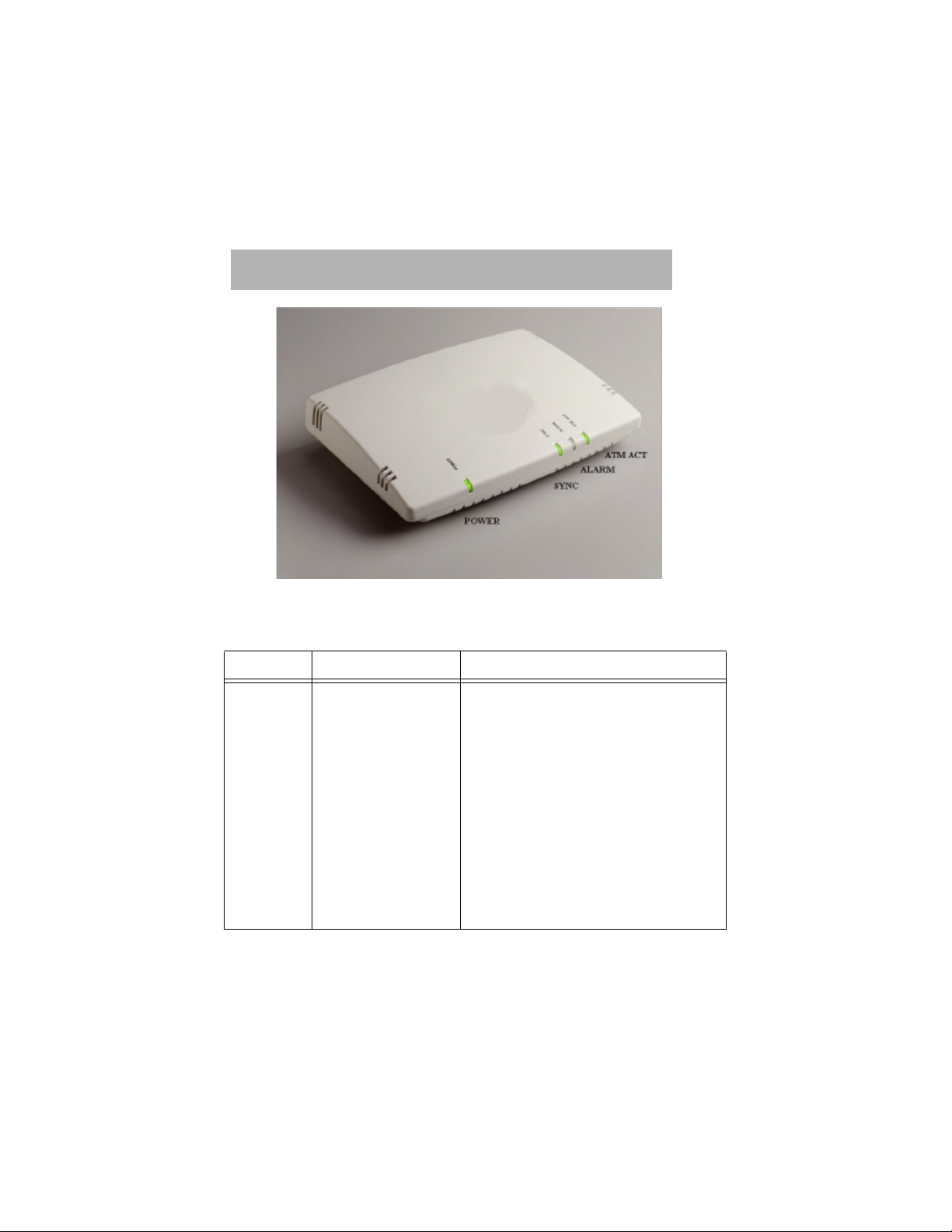
1.3 Front Status Indicators
The Front panel includes four status indicators as shown in the table below:
LEDs COLOR EXPLANATION
POWER Green (solid) It will illuminate as soon as the device is
powered ON and will remain on till the
device is turned OFF.
SYNC Green (solid) It illuminates to indicate successful
connection to the Network.
ALARM Red (solid) It indicates the device encountering an error.
ATM ACT Green (solid/blinking) The ATM Activity LED shows data traffic.
During normal operation, it should be
blinking.
2 SMC7003ADSL (version 1.0)
Page 7
Chapter 1 - Product Description
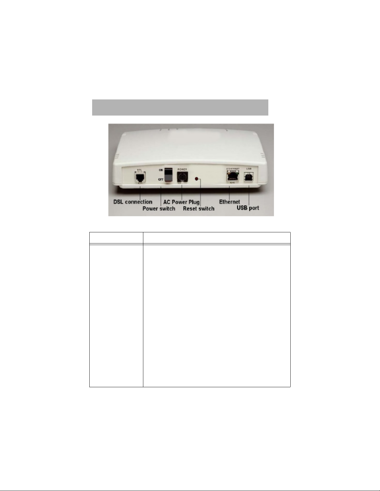
1.4 Rear Panel
EXPLANATION
DSL RJ-11 port for DSL connection (cable provided).
POWER SWITCH Permits the device to be turned ON/OFF.
POWER OUTLET A receptacle for the AC Power Adapter.
RESET SWITCH To return the device to factory settings.
ETHERNET Allows the SMC7003ADSL to establish a connection either to
a hub or directly to a PC and requires a RJ-45 cable
(provided). It has 2 LEDs. The Link LED (green) remains
solid when connected to an active Ethernet port. The Activity
LED (yellow) will blink when there is traffic.
USB Allows a direct connection to a PC for greater flexibility and
simultaneous sharing of local resources and the ADSL line
(cable provided).
SMC7003ADSL (version 1.0) 3
Page 8

Chapter 1 - Product Description
1.5 Parameters From Service Provider
Depending on Service Providers, automatic configuration or the following parameters
may be provided by the Service Provider (ISP) for configuring the PC or Router.
Example shown below:
4 IP Address 10 . 10 . 12 . 102
4 Subnet Mask Address 255 . 255 . 255 . 0
4 Gateway Address 10 . 10 . 12 . 1
4 DNS Server Address 202 . 23 . 3 . 75
4 Domain Address 10 . 10 . 12 . 40
4 vci value (default: vci=35) 35
4 vpi value (default: vpi=0) 0
4 SMC7003ADSL (version 1.0)
Page 9

Chapter 1 - Product Description
WORKSHEET
PLEASE HAVE THIS INFORMATION BEFORE YOU PROCEED:
4 IP Address ___ . ___ . ___ . ___
4 Subnet Mask Address ___ . ___ . ___ . ___
4 Gateway Address ___ . ___ . ___ . ___
4 DNS Server Address ___ . ___ . ___ . ___
4 Domain Address ___ . ___ . ___ . ___
4 vci value (default: vci=35) ___
4 vpi value (default: vpi=0) ___
NOTE:
a If vci/vpi values are the same as the default, you do not need to make any
changes in the Bridge Mode.
a Extra copy of this page is provided on the last page of this manual.
SMC7003ADSL (version 1.0) 5
Page 10

Chapter 1 - Product Description
1.6 Default Settings
SYSTEM MODULE
4 ip-address : 10.0.0.1
4 subnet-mask : 255.255.255.0
4 user name : admin
4 password : password (minimum 4 alphabetic characters)
4 language : english
ATM MODULE
4 vc-no : 0
4 vpi : 0
4 vci : 35
4 vc-type : ATM_PVC
4 encap type : LLC_MUX
4 encap protocol : RFC1483 (BRIDGED)
6 SMC7003ADSL (version 1.0)
Page 11
Chapter 2 - Installation
Chapter 2 - Installation
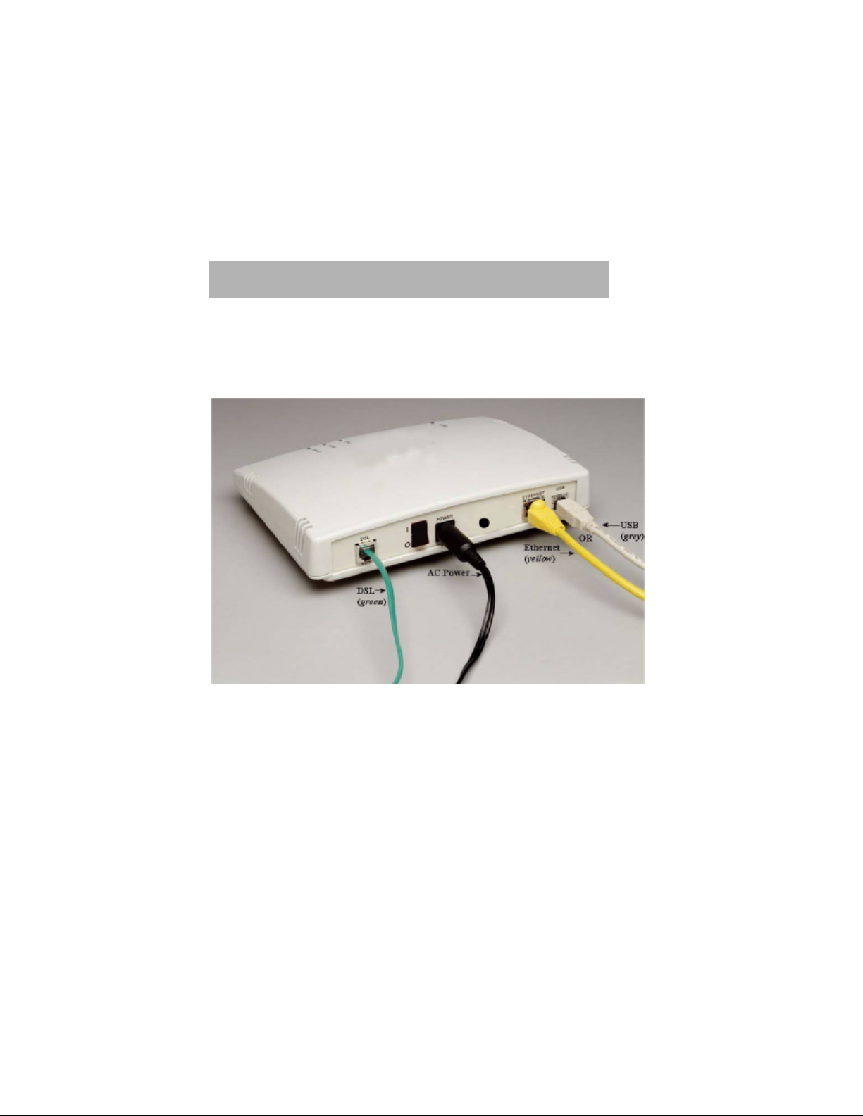
2.1 Hardware Installation Procedures
The following steps are recommended to complete the SMC7003ADSL installation and
setup procedures.
Cable connections to the Rear Panel of the SMC7003ADSL.
SMC7003ADSL (version 1.0) 7
Page 12

Chapter 2 - Installation
2.1.1 ETHERNET CONNECTION
1. Check if the Ethernet card and the TCP/IP are installed on the PC before beginning
installation. (If the TCP/IP protocol is not installed, go to Appendix B for the
installation procedures).
2. Connect the Ethernet cable (yellow) from the SMC7003ADSL’s Ethernet port to the
Ethernet port of the PC.
3. Connect the DSL cable (green) in to the DSL wall jack and the other end in to
receptacle marked “DSL RJ-11” on the back of the device.
4. Connect the AC Power Adapter to the AC wall output and connect the round cable
end to the “Power” receptacle on the back of the device.
5. Connect the AC Power Adapter to the AC wall output and connect the round cable
end to the “Power” receptacle on the back of the SMC7003ADSL.
6. Turn ON the unit by using the ON/OFF switch in the back of the device to the ON
position. You must have a steady (green) Power LED. The Sync LED will be a
blinking (green) LED initially and will become steady (green) once the connection is
established.
8 SMC7003ADSL (version 1.0)
Page 13

Chapter 2 - Installation
2.1.2 USB CONNECTION
1. Connect the DSL cable (green) in to the DSL wall jack and the other end in to
receptacle marked “DSL RJ-11” on the back of the SMC7003ADSL.
2. Connect the Power cord to the AC Power Adapter.
3. Connect the AC Power Adapter to the AC wall output and connect the round cable
end to the “Power” receptacle on the back of the device.
4. Turn ON the SMC7003ADSL by using the ON/OFF switch in the back of the device
to the ON position. You must have a steady (green) Power LED. The Sync LED will
be a blinking (green) LED initially and will become steady (green) once the
connection is established.
5. Locate the USB port of the PC. It is marked with the typical USB symbol.
6. Plug the square side of the USB cable’s one end (grey cable) in to the
SMC7003ADSL device’s USB port and the other flat long end to the USB port of the
PC. (If the PC is running, it will automatically detect the USB port Driver).
NOTE: aWindows NT 4.0 does not support USB.
aUSB port may have some compatibility issues with Windows 95.
7. Follow instructions on how to load the USB driver for the SMC7003ADSL (USB
Installation - Section I. How to install the USB Driver).
SMC7003ADSL (version 1.0) 9
Page 14

Chapter 2 - Installation
2.2 Connecting the PC to the SMC7003ADSL
2.2.1 ETHERNET CONNECTION (Windows 95/98 & Windows Me
style dialog box shown as an example)
A. Configuration of the PC for the GUI:
1. Follow Steps 1 through 5 as shown on the next page and restart the PC.
2. In Step 5, the IP address needs to be of the same class as the SMC7003ADSL. For
example: The IP address should be 10.0.0.2 if the default IP address of the unit is
10.0.0.1.
3. The Subnet Mask should be 255.255.255.0.
B. If the SMC7003ADSL is configured as a Bridge:
1. Follow Steps 1 through 14 as shown on the next page using the ISP parameters
from the worksheet.
C. If the SMC7003ADSL is configured as a Router:
1. Follow Steps 1 through 4 as shown on the next page.
2. In Step 5, select Obtain an IP Address Automatically.
3. Continue to Step 6.
4. In Step 7, the Gateway Address is the LAN IP Address of the unit. By default, it
is 10.0.0.1.
10 SMC7003ADSL (version 1.0)
Page 15

Chapter 2 - Installation
1. Click Start on the Task Bar of the PC, select Settings and select Control Panel.
2. Double-click the Network icon.
3. In the Configuration window, select the TCP/IP Protocol associated with the
installed Ethernet card.
SMC7003ADSL (version 1.0) 11
Page 16

Chapter 2 - Installation
4. Click the Properties button and select IP Address tab.
5. Select Specify an IP Address and fill in the fields with the IP Address and
Subnet Mask from the work sheet.
6. Continue the settings by clicking the Gateway tab.
12 SMC7003ADSL (version 1.0)
Page 17

Chapter 2 - Installation
7. Enter the Gateway IP Address from the work sheet.
8. Click Add.
9. Click the DNS Configuration tab to continue with the settings.
SMC7003ADSL (version 1.0) 13
Page 18

Chapter 2 - Installation
10. Click Enable DNS.
11. Enter Host name and Domain name from the work sheet.
12. Under the DNS Server Search Order, enter the DNS Server IP Address as
entered in the work sheet.
13. Click Add.
14. Click OK and follow instructions to restart the PC.
14 SMC7003ADSL (version 1.0)
Page 19

Chapter 2 - Installation
2.2.2 USB INSTALLATION (Windows 95/98 and Windows Me style
dialog box shown as an example)
NOTE: aUSB port may have some compatibility issues with Windows95.
2.2.2.1 How To Install The USB Driver
1. If the PC is running, the Wizard will begin a search for USB drivers. If the
Wizard is unable to find the driver, it will ask the user to decide the location. (If
the PC finds the driver, go directly to Configuring the PC for the USB.
2. If the PC cannot find the USB driver hardware, go to Start, select Settings and
Control Panel and double-click on Add New Hardware. Click Next.
3. Under ‘Is the device that you want to install listed below?’ choose No, the
device isn’t in the list. Click Next.
4. In ‘Do you want Windows to search for new hardware?’ choose Yes
(Recommended). Click Next.
5. Select the option Search for best driver for your device (Recommended) and
click Next.
6. Select CD Drives and click Next. The PC will begin loading the first USB
driver which is vvususb.sys. A window shows the USB driver loading.
7. Click Finish and the Wizard window will show that it has detected another
driver SMC7003ADSL vv PC-attached gateway. Click Next.
8. Select the CD Drives and click Next. The PC will begin loading the second
USB driver which is vvbeth.sys. A window shows the USB driver loading.
9. Click Finish and restart the PC to bring the new configurations into effect.
10. On Windows 2000, all the steps are the same till step 8. The PC does not
require to be restarted.
SMC7003ADSL (version 1.0) 15
Page 20

Chapter 2 - Installation
2.2.2.2 Configuring The PC For The USB
1. Click Start on the Task Bar of the PC, select Settings and Control Panel.
2. Double-click the Network icon.
3. From the Configuration window, select the TCP/IP protocol which shows TCP/IP
[ SMC7003ADSL VVB PC-attached gateway.
4. Follow Step 4 through Step 14 from the Ethernet Connection to complete the
setup.
16 SMC7003ADSL (version 1.0)
Page 21

Chapter 3 - Configuration
Chapter 3 - Configuration
3.1 GUI Installation
The following procedures are recommended to configure the SMC7003ADSL through the
GUI.
Before you begin, you need to install the GUI software from the 3 1/2" Floppy Diskette
provided in the package.
1. Insert the Floppy Diskette with the GUI in to the PC 3 1/2" Floppy drive.
2. Double-click the file “GUI_Setup”.
3. Click “Unzip”. The program will automatically extract all the GUI files to a new
directory called ‘ADSLRouter’ on the C drive.
4. After the files are unzipped, click “Ok” and select “Close” to terminate the Winzip
Application.
5. Open the directory “ADSLRouter” in the C Drive.
6. Double-click on the executable file “ADSLRouter” to begin accessing the GUI.
SMC7003ADSL (version 1.0) 17
Page 22
Chapter 3 - Configuration
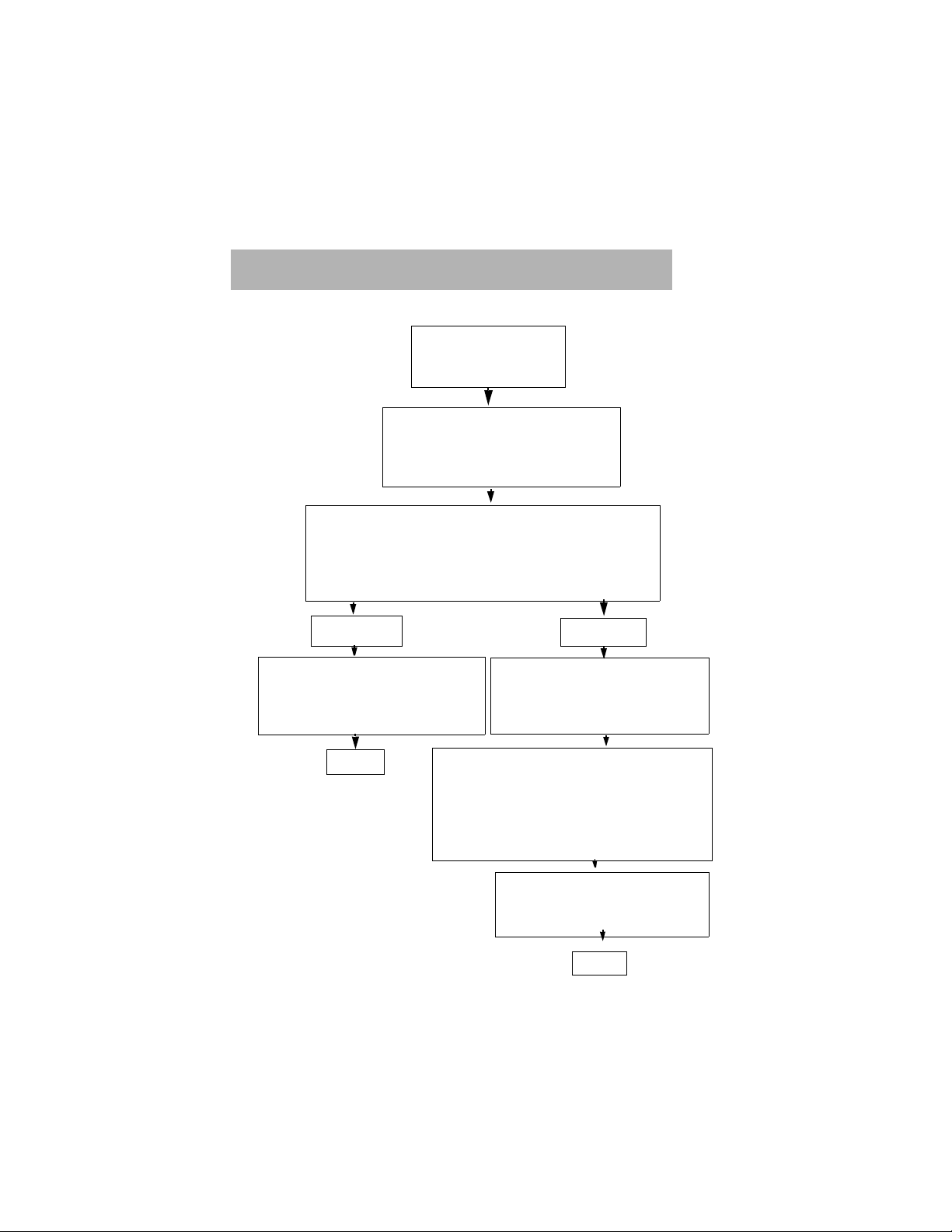
3.2 Easy Setup Flow Chart
Advanced Setup (for Administrator)
Log in to the System
Username: admin
Password : password
SMC7003ADSL Setup
Easy Setup (default)
SELECT: Option to configure the mode of operation
Note :
BRIDGING
ENTER: DSL Parameters
Note : DSL Parameters provided
by Service Provider
Bridge/ Router
The mode of operation (Bridge or Router) of the
DSL line is provisioned by the Service Provider
SELECT: Ethernet and/or USB
Note : Each port will have its
EXIT
CONFIGURE: Parameters for Ethernet and/
or USB ports
Note : Ethernet-the unit can distribute
ENTER: DSL Parameters
Note : DSL Parameters provided
ROUTING
own IP address
IP address to more than 1 PC
on the network
by Service Provider
EXIT
18 SMC7003ADSL (version 1.0)
Page 23

Chapter 3 - Configuration
3.3 Login Screen
• The Device Type is Ethernet.
• Choose admin under the User
Name and enter the password as
password.
• Click Login.
• The default choice is Easy
Setup.
• Click OK.
SMC7003ADSL (version 1.0) 19
Page 24

Chapter 3 - Configuration
3.4 Bridge Mode Configuration
• Click on Cancel to exit the
GUI.
• Select Yes in ‘Do you want to
update the Bridge Mode?’.
• Click Next to change current
Bridge configuration.
• Enter the LAN IP address
(shown is the default LAN IP
address of the SMC7003ADSL).
• Enter the DSL Parameters in
the WAN Parameters boxes
entered from the work sheet.
• Click on Finish to end the
configuration.
20 SMC7003ADSL (version 1.0)
Page 25

Chapter 3 - Configuration
• The SMC7003ADSL Status Window will appear as shown above.
• Select DSL or IP to view the current statistics.
• Or select Advanced to make further changes in the configuration.
• Select Save and Exit to exit the GUI.
• The Current Configuration Window will appear as shown above.
• Select Save to save the current details in a configuration file.
• Or select OK to save and exit the GUI without saving the current
configuration details in a file for viewing later.
SMC7003ADSL (version 1.0) 21
Page 26

Chapter 3 - Configuration
3.5 Router Mode Configuration
• The default settings of the
device is RFC1483 Bridged.
• If you do not want to make any
further changes, select Cancel.
• If you want to make changes,
in ‘Do you want to change to
Routed Mode?’, choose Yes.
• Click Next.
• Choose the Device Type i.e:
Ethernet or Ethernet and
USB.
• Click Next.
22 SMC7003ADSL (version 1.0)
Page 27

Chapter 3 - Configuration
• Enter the LAN IP address of
the SMC7003ADSL.
• Enter the Number of PCs
connected to that port.
• Click Next.
• Enter the WAN IP Address as
entered in the work sheet.
• Enter the Gateway Address.
• Enter The vpi/vci values. (The
default vpi/vci values are 0 and
35).
• Enable or Disable NAT as
required.
• Click Finish.
SMC7003ADSL (version 1.0) 23
Page 28

Chapter 3 - Configuration
• The SMC7003ADSL Status Window will appear as shown above.
• Select DSL or IP to view current statistics.
• Or select Advanced to make further changes in the configuration.
• Select Save and Exit to exit the GUI.
• The Current Configuration Window will appear as shown above.
• Select Save to save the current details in a configuration file.
• Or select OK to save and exit the GUI without saving the current
configuration details in a file for viewing later.
24 SMC7003ADSL (version 1.0)
Page 29

Chapter 4 - Warranty and Shipping Information
Chapter 4 - Warranty & Shipping
Information
4.1 Customer Service and Technical Support
From USA and Canada (8.30 AM - 8.00 PM Pacific Time)
Toll Free : 1 - 800 - SMC 4 YOU
Tel : (949) 707 2400
Fax : (949) 707 2460
From Europe (8.00 AM - 5.30 PM UK Greenwich Mean Time)
Tel : 44 - 0 - 11 - 89 74 8740
Fax : 44 - 0 - 11 - 89 74 8741
INTERNET
E-Mail Addresses:
techsupport@smc.com
european.techsupport@smc-europe.com
Driver Updates:
http://www.smc.com/smc/pages_html/support.html
World Wide Web:
http://www.smc.com
FTP Site:
ftp://ftp.smc.com
SMC7003ADSL (version 1.0) 25
Page 30

Chapter 4 - Warranty and Shipping Information
4.2 SMC’s Limited Warranty
Limited Warranty Statement:
SMC Networks, Inc. (“SMC”) warrants its products to be free from defects
in workmanship and materials, under normal use and service, for the
applicable warranty term. All SMC products carry a standard 90-day
limited warranty from the date of purchase from SMC or its Authorized
Reseller. SMC may, at its own discretion, repair or replace any product not
operating as warranted with a similar or functionally equivalent product,
during the applicable warranty term. SMC will endeavor to repair or
replace any product returned under warranty within 30 days of receipt of
the product.
The standard limited warranty can be upgraded to a Limited Lifetime*
warranty by registering new products within 30 days of purchase from
SMC or its Authorized Reseller. Registration can be accomplished online
via the SMC web site. Failure to register will not affect the standard limited
warranty. The Limited Lifetime warranty covers a product during the Life
of that Product, which is defined as the period of time during which the
product is an ‘Active’ SMC product. A product is considered to be ‘Active’
while it is listed on the current SMC price list. As new technologies
emerge, older technologies become obsolete and SMC will, at its discretion, replace an older product in its product line with one that incorporates
these newer technologies. At that point, the obsolete product is discontinued and is no longer an ‘Active’ SMC product. A list of discontinued products with their respective dates of discontinuance can be found at:
http://www.smc.com/smc/pages_html/support.html.
All products that are replaced become the property of SMC. Replacement
products may be either new or reconditioned. Any replaced or repaired
product carries either a 30-day limited warranty or the remainder of the
initial warranty, whichever is longer. SMC is not responsible for any
custom software or firmware, configuration information, or memory data
of Customer contained in, stored on, or integrated with any products
returned to SMC pursuant to any warranty. Products returned to SMC
should have any customer-installed accessory or add-on components, such
as expansion modules, removed prior to returning the product for
replacement. SMC is not responsible for these items if they are returned
with the product.
26 SMC7003ADSL (version 1.0)
Page 31

Chapter 4 - Warranty and Shipping Information
Customers must contact SMC for a Return Material Authorization number
prior to returning any product to SMC. Proof of purchase may be required.
Any product returned to SMC without a valid Return Material
Authorization (RMA) number clearly marked on the outside of the package
will be returned to customer at customer’s expense. For warranty claims
within North America, please call our toll-free customer support number at
(800) 762-4968. Customers are responsible for all shipping charges from
their facility to SMC. SMC is responsible for return shipping charges from
SMC to customer.
WARRANTIES EXCLUSIVE:
IF AN SMC PRODUCT DOES NOT OPERATE AS WARRANTED
ABOVE, CUSTOMER’S SOLE REMEDY SHALL BE REPAIR OR
REPLACEMENT OF THE PRODUCT IN QUESTION, AT SMC’S
OPTION. THE FOREGOING WARRANTIES AND REMEDIES ARE
EXCLUSIVE AND ARE IN LIEU OF ALL WARRRANTIES OR
CONDITIONS, EXPRESS OR IMPLIED, EITHER IN FACT OR BY
OPERATION OF LAW STATUORY OR OTHERWISE, INCLUDING
WARRANTIES OR CONDITIONS OF MERCHANTABILITY AND
FITNESS FOR A PARTICULAR PURPOSE. SMC NEITHER ASSUMES
NOR AUTHORIZES ANY OTHER PERSON TO ASSUME FOR IT
ANY OTHER LIABILITY IN CONNECTION WITH THE SALE.
INSTALLATION, MAINTENANCE OR USE OF ITS PORDUCTS. SMC
SHALL NOT BE LIABLE UNDER THIS WARRANTY IF ITS
TESTING AND EXAMINATION DISCLOSE THE ALLEGED DEFECT
IN THE PRODUCT DOES NOT EXIST OR WAS CAUSED BY
CUSTOMER’S OR ANY THIRD PERSON’S MISUSE, NEGLECT,
IMPROPER INSTALLATION OR TESTING, UNAUTHORIZED
ATTEMPTS TO REPAIR, OR ANY OTHER CAUSE BEYOND THE
RANGE OF THE INTENDED USE, OR BY ACCIDENT, FIRE,
LIGHTNING, OR OTHER HAZARD.
SMC7003ADSL (version 1.0) 27
Page 32

Chapter 4 - Warranty and Shipping Information
LIMITATION OF LIABILITY:
IN NO EVENT, WHETHER BASED IN CONTRACT OR TORT
(INCLUDING NEGLIGENCE), SHALL SMC BE LIABLE FOR
INCIDENTAL, CONSEQUENTIAL, INDIRECT, SPECIAL, OR
PUNITIVE DAMAGES OF ANY KIND, OR FOR LOSS OF REVENUE,
LOSS OF BUSINESS, OR OTHER FINANCIAL LOSS ARISING OUT
OF OR IN CONNECTION WITH THE SALE, INSTALLATION,
MAINTENANCE, USE, PERFORMANCE, FAILURE OR
INTERRUPTION OF ITS PRODUCTS, EVEN IF SMC OR ITS
AUTHORIZED RESELLER HAS BEEN ADVISED OF THE
POSSIBILITY OF SUCH DAMAGES.
SOME STATES DO NOT ALLOW THE EXCLUSION OF IMPLIED
WARRANTIES OR THE LIMITATION OF INCIDENTAL OR
CONSEQUENTIAL DAMAGES FOR CONSUMER PRODUCTS, SO
THE ABOVE LIMITATIONS AND EXCLUSIONS MAY NOT APPLY
TO YOU. THIS WARRANTY GIVES YOU SPECIFIC LEGAL RIGHTS,
WHICH MAY VARY FROM STATE TO STATE. NOTHING IN THIS
WARRANTY SHALL BE TAKEN TO AFFECT YOUR STATUTORY
RIGHTS.
* SMC will provide warranty service for one year following
discontinuance from the active SMC price list. Under the limited lifetime
warranty, internal and external power supplies, fans, and cables are
covered by a standard one-year warranty from date of purchase.
28 SMC7003ADSL (version 1.0)
Page 33

Appendix A - FCC Notice
Appendix A - Fcc Notice
According to Federal Communications Commission (FCC) Rules regarding radio
frequency emissions, the SMC7003ADSL complies with FCC Part 15 for Class B
computing devices. The following paragraph is required by the FCC.
This equipment generates, uses and can radiate radio frequency energy and if not
installed and used in accordance with this document, may cause interference to
radio communications. It has been tested and found to comply with the limits for a
Class B computing device pursuant to Part 15 of FCC Rules. These limits are
designed to provide reasonable protection against such interference when the
equipment is operated in a commercial environment. Operation of this equipment
in a residential area is likely to cause interference, in which case, the user, at his
own expense, is required to take whatever measures may be necessary to correct
the interference.
If this equipment does cause harmful interference to radio or television reception,
the user is encouraged to try to correct the interference by one or more of the
following measures:
• Turn the equipment “OFF” and “ON”.
• Reorient or relocate the receiving antenna.
• Increase distance between equipment and receiver.
• Connect the equipment to an outlet on a circuit different
from which the receiver is connected.
NOTE
Any changes or modifications not expressly
approved by the grantee of this device could
void the user’s authority to operate the
equipment.
SMC7003ADSL (version 1.0) 29
Page 34

Appendix A - FCC Notice
Meets Canadian D.O.C.
This product conforms with Canadian Class B Emissions Regulations.
Meets Approvals
Safety : FCC Part 68, EN60950, UL 1950, C/UL to CSA 22.2 No.950,
TUV, IC CS03
Emissions : FCC Part 15 Class B, EN55022 / CISPR2 Class B
Immunity : EN55024
30 SMC7003ADSL (version 1.0)
Page 35

Appendix B - Installation of TCP/IP Protocol
Appendix B - Installation of TCP/
IP Protocol
Before you begin the TCP/IP protocol installation, check if the Ethernet card has
been installed inside the PC.
These instructions are based on Windows 95, 98 and Windows Me. For the TCP/IP
setup under Windows NT and Windows 2000, please refer to the Windows manual.
1. Click Start on the Task Bar of the PC and select Settings and Control Panel.
2. Double-click the Network icon.
3. Select the Configuration tab.
4. Click on Add.
5. Select Network Component Type i.e: Protocol and Click Add.
SMC7003ADSL (version 1.0) 31
Page 36

Appendix B - Installation of TCP/IP Protocol
6. Select the Manufacturer’s Name of your Network Card and double-click TCP/IP
in the list.
7. The PC will return to the main Network window. Check if the TCP/IP Protocol
appears in the list.
8. Click OK. Windows may ask for the Windows95/98 CD or the original installation
files (i.e.: D:/win95, D:/win98 or c:\windows\options\cabs).
9. Click OK and follow instructions to restart the PC.
32 SMC7003ADSL (version 1.0)
Page 37

Appendix C - Interface Pin Assignments
Appendix C - Interface Pin
Digital Subscriber Line (RJ-11)
a Signal Name Pin
Tip 3
Ring 4
Ethernet (RJ-45)
a Signal Name Pin
RD + 1
RD - 2
TD + 3
TD - 6
Assignments
SMC7003ADSL (version 1.0) 33
Page 38

PARAMETERS FROM SERVICE PROVIDER
Depending on Service Providers, automatic configuration or the following parameters
may be provided by the Service Provider (ISP) for configuring the PC or Router.
Example shown below:
4 IP Address 10 . 10 . 12 . 102
4 Subnet Mask Address 255 . 255 . 255 . 0
4 Gateway Address 10 . 10 . 12 . 1
4 DNS Server Address 202 . 23 . 3 . 75
4 Domain Address 10 . 10 . 12 . 40
4 vci value (default: vci=35) 35
4 vpi value (default: vpi=0) 0
----------------------------------------------------------------------------------------------
WORKSHEET
PLEASE HAVE THIS INFORMATION BEFORE YOU PROCEED:
4 IP Address ___ . ___ . ___ . ___
4 Subnet Mask Address ___ . ___ . ___ . ___
4 Gateway Address ___ . ___ . ___ . ___
4 DNS Server Address ___ . ___ . ___ . ___
4 Domain Address ___ . ___ . ___ . ___
4 vci value (default: vci=35) ___
4 vpi value (default: vpi=0) ___
NOTE: aIf vci/vpi values are the same as the default, you do not need to make
any changes in the Bridge Mode.
SMC7003ADSL (version 1.0) 34
 Loading...