

Page 1

TigerSwitch 100
User Guide
From SMC’s Tiger line of feature-rich workgroup LAN solutions
March 1998
900.168 Rev. B
Page 2

TigerSwitch 100
8-port Fast Ethernet Switches
◆ Two models featuring either:
◆ Eight fixed Auto-Negotiating 100BASE-TX ports
◆ Two 4-port replaceable modules with 100BASE-TX
and/or 100BASE-FX ports
◆ 1.6 Gbps internal bandwidth
◆ In-band and out-of-band management
User Guide
SMC6608T SMC6608M
Page 3

Information furnished by SMC Networks, Inc. (SMC) is believed
to be accurate and reliable. However, no responsibility is
assumed by SMC for its use, nor for any infringements of
patents or other rights of third parties which may result from its
use. No license is granted by implication or otherwise under
any patent or patent rights of SMC. SMC reserves the right to
change specifications at any time without notice.
Copyright © 1997 by
SMC Networks, Inc.
Hauppauge, New York.
All rights reserved. Printed in U.S.A.
Trademarks:
SMC is a registered trademark; and TigerSwitch, TigerStack, EZ Hub, EZ Switch and
EliteFax are trademarks of SMC Networks, Inc. Other product and company names are
trademarks or registered trademarks of their respective holders.
Page 4

Limited Warranty
HARDWARE: SMC Networks, Inc. (“SMC”) warrants these TigerSwitch 100 units
to be free from defects in workmanship and materials, under normal use and
service, for the following length of time from the date of purchase from SMC or
its Authorized Reseller:
TigerSwitch 100 . . . . . . . . . . . . . . . . . . . . . . . . . . . . . . . . . . . .Three Years
If a product does not operate as warranted during the applicable warranty
period, SMC shall, at its option and expense, repair the defective product or
part, deliver to Customer an equivalent product or part to replace the defective
item, or refund to customer the purchase price paid for the defective product.
All products that are replaced will become the property of SMC. Replacement
products may be new or reconditioned. Any replaced or repaired product or
part has a ninety (90) day warranty or the remainder of the initial warranty
period, whichever is longer.
SMC shall not be responsible for any custom software or firmware, configuration information, or memory data of Customer contained in, stored on, or
integrated with any products returned to SMC pursuant to any warranty.
SOFTWARE: SMC warrants that the software programs licensed from it will
perform in substantial conformance to the program specifications for a period
of ninety (90) days from the date of purchase from SMC or its Authorized
Reseller. SMC warrants the magnetic media containing software against failure
during the warranty period. No updates are provided. SMC’s sole obligation
hereunder shall be (at SMC’s discretion) to refund the purchase price paid by
Customer for any defective software products or to replace any defective media
with software which substantially conforms to SMC’s applicable published specifications. Customer assumes responsibility for the selection of the appropriate
applications program and associated reference materials. SMC makes no warranty that its software products will work in combination with any hardware or
applications software products provided by third parties, that the operation of
the software products will be uninterrupted or error free, or that all defects in
the software products will be corrected. For any third party products listed in
the SMC software product documentation or specifications as being compatible,
SMC will make reasonable efforts to prove compatibility, except where the
non-compatibility is caused by a “bug” or defect in the third party’s product.
STANDARD WARRANTY SERVICE: Standard warranty service for hardware
products may be obtained by delivering the defective product, accompanied
by a copy of the dated proof of purchase, to SMC’s Service Center or to an
Authorized SMC Service Center during the applicable warranty period. Standard
warranty service for software products may be obtained by telephoning SMC’s
Service Center or an Authorized SMC Service Center, within the warranty
period. Products returned to SMC’s Service Center must be pre-authorized by
Page 5

LIMITED WARRANTY
SMC with a Return Material Authorization (RMA) number marked on the outside of the package, and sent prepaid, insured, and packaged appropriately for
safe shipment. The repaired or replaced item will be shipped to Customer, at
SMC’s expense, not later than thirty (30) days after receipt by SMC.
WARRANTIES EXCLUSIVE: IF AN SMC PRODUCT DOES NOT OPERATE AS
WARRANTED ABOVE, CUSTOMER’S SOLE REMEDY SHALL BE REPAIR,
REPLACEMENT OR REFUND OF THE PURCHASE PRICE PAID, AT SMC’S
OPTION. THE FOREGOING WARRANTIES AND REMEDIES ARE EXCLUSIVE
AND ARE IN LIEU OF ALL OTHER WARRANTIES OR CONDITIONS, EXPRESS
OR IMPLIED, EITHER IN FACT OR BY OPERATION OF LAW, STATUTORY OR
OTHERWISE, INCLUDING WARRANTIES OR CONDITIONS OF MERCHANTABILITY AND FITNESS FOR A PARTICULAR PURPOSE. SMC NEITHER
ASSUMES NOR AUTHORIZES ANY OTHER PERSON TO ASSUME FOR IT ANY
OTHER LIABILITY IN CONNECTION WITH THE SALE, INSTALLATION, MAINTENANCE OR USE OF ITS PRODUCTS.
SMC SHALL NOT BE LIABLE UNDER THIS WARRANTY IF ITS TESTING AND
EXAMINATION DISCLOSE THE ALLEGED DEFECT IN THE PRODUCT DOES
NOT EXIST OR WAS CAUSED BY CUSTOMER’S OR ANY THIRD PERSON’S
MISUSE, NEGLECT, IMPROPER INSTALLATION OR TESTING, UNAUTHORIZED
ATTEMPTS TO REPAIR, OR ANY OTHER CAUSE BEYOND THE RANGE OF
THE INTENDED USE, OR BY ACCIDENT, FIRE, LIGHTNING, OR OTHER
HAZARD.
LIMITATION OF LIABILITY: IN NO EVENT, WHETHER BASED IN CONTRACT
OR TORT (INCLUDING NEGLIGENCE) SHALL SMC BE LIABLE FOR INCIDENTAL, CONSEQUENTIAL, INDIRECT, SPECIAL, OR PUNITIVE DAMAGES OF
ANY KIND, OR FOR LOSS OF REVENUE, LOSS OF BUSINESS, OR OTHER
FINANCIAL LOSS ARISING OUT OF OR IN CONNECTION WITH THE SALE,
INSTALLATION, MAINTENANCE, USE, PERFORMANCE, FAILURE, OR INTERRUPTION OF ITS PRODUCTS, EVEN IF SMC OR ITS AUTHORIZED RESELLER
HAS BEEN ADVISED OF THE POSSIBILITY OF SUCH DAMAGES. NOTHING
HEREIN SHALL HAVE THE EFFECT OF LIMITING OR EXCLUDING SMC’S
LIABILITY FOR DEATH OR PERSONAL INJURY CAUSED BY NEGLIGENCE.
Some states do not allow the exclusion of implied warranties or the limitation
of incidental or consequential damages for consumer products, so the above
limitations and exclusions may not apply to you. This warranty gives you specific legal rights which may vary from state to state. Nothing in this warranty
shall be taken to affect your statutory rights.
SMC
350 Kennedy Drive
Hauppauge, NY 11788
516-435-6000
Page 6

TABLE OF CONTENTS
Compliances.......................................................... v
1 About The TigerSwitch 100........................... 1-1
TigerSwitch 100 Overview ................................................. 1-3
Switch Architecture............................................................. 1-10
Management Options ......................................................... 1-12
Key Features and Benefits.................................................. 1-13
2 Planning......................................................... 2-1
Introduction to Switching................................................... 2-2
Sample Applications ........................................................... 2-3
3 Installation..................................................... 3-1
Selecting a Site.................................................................... 3-2
Equipment Checklist........................................................... 3-3
Mounting ............................................................................. 3-4
Powering Up....................................................................... 3-7
Making Network Connections............................................ 3-9
4 Configuration and Management.................. 4-1
Configuration Options........................................................ 4-3
Basic Port Settings............................................................... 4-4
Advanced System Configuration........................................ 4-5
System Monitoring .............................................................. 4-19
Advanced System Monitoring............................................. 4-21
Downloading System Software .......................................... 4-28
Resetting the Switch............................................................ 4-30
5 Management via SNMP.................................. 5-1
SNMP Protocol .................................................................... 5-2
MIB Objects......................................................................... 5-3
SNMP Parameter Configuration.......................................... 5-4
i
Page 7

TABLE OF CONTENTS
Appendices
A Troubleshooting............................................ A-1
Switch Indicators................................................................. A-2
Diagnostic Tests.................................................................. A-3
System Diagnostics ............................................................. A-4
B Pin Assignments............................................ B-1
RJ-45 Pin Assignments........................................................ B-2
Console Port Pin Assignments ........................................... B-4
C Specifications ................................................ C-1
All Models ........................................................................... C-2
SMC6608T............................................................................ C-4
SMC6608M........................................................................... C-4
D Glossary ......................................................... D-1
ii
Page 8

TABLE OF CONTENTS
List of Figures
1-1. TigerSwitch 100T with 8 10BASE-T/100BASE-TX Ports
(Model SMC6608T)..................................................... 1-4
1-2. TigerSwitch 100M Base Unit...................................... 1-4
1-3. 4-Port Fast Ethernet Modules .................................... 1-4
1-4. 10BASE-T/100BASE-TX Ports .................................... 1-6
1-5. 100BASE-FX Ports ...................................................... 1-6
1-6. Front Panel LEDs........................................................ 1-7
1-7. Front Panel LED Arrays.............................................. 1-7
1-8. Console Port............................................................... 1-8
1-9. Configure Button........................................................ 1-8
1-10. Power Supply Receptacles......................................... 1-9
2-1. Collapsed Backbone.................................................. 2-3
2-2. Multiport Bridging Connections................................ 2-4
2-3. Server Farm Connectivity and Expansion................. 2-5
2-4. Cascading to a Fast Ethernet Switch......................... 2-6
2-5. Collapsed Backbone Using Fiber Cable ................... 2-7
2-6. High-Speed Fiber Backbone ..................................... 2-8
3-1. Attaching the Brackets............................................... 3-5
3-2. Installing the Switch in a Rack.................................. 3-5
3-3. Attaching the Adhesive Feet...................................... 3-6
3-4. Switch-Selectable Daisy-Chain Port ......................... 3-12
3-5. Fiber Cable Connectors ............................................. 3-13
4-1. System Configuration Program Login Screen........... 4-7
4-2. System Configuration Program Main Menu.............. 4-8
4-3. Password Configuration Screen................................. 4-10
4-4. Console Configuration Screen................................... 4-11
4-5. System Configuration Screen..................................... 4-12
4-6. Port Configuration Screen.......................................... 4-14
4-7. Spanning Tree Configuration Screen........................ 4-16
iii
Page 9

TABLE OF CONTENTS
4-8. Virtual LAN Configuration Screen............................. 4-18
4-9. System Information Screen........................................ 4-21
4-10. Port Status Screen....................................................... 4-22
4-11. Statistics Screen .......................................................... 4-23
4-12. Address Table Screen................................................. 4-25
4-13. Spanning Tree Information Screen ........................... 4-26
4-14. TFTP Download Screen............................................. 4-28
4-15. Reset Screen ............................................................... 4-30
5-1. SNMP Configuration Screen ...................................... 5-4
5-2. Community Strings Screen......................................... 5-5
5-3. Trap Receivers Screen................................................ 5-6
B-1. RJ-45 Connector Pin Numbers................................... B-2
B-2. DB-9 Console Port Pin Numbers............................... B-4
iv
Page 10

COMPLIANCES
FCC - Class A
This equipment generates, uses, and can radiate radio frequency energy and, if
not installed and used in accordance with the instruction manual, may cause
interference to radio communications. It has been tested and found to comply
with the limits for a Class A computing device pursuant to Subpart B of Part 15
of FCC Rules, which are designed to provide reasonable protection against such
interference when operated in a commercial environment. Operation of this
equipment in a residential area is likely to cause interference, in which case the
user, at his own expense, will be required to take whatever measures may be
required to correct the interference. You are cautioned that changes or modifications not expressly approved by the party responsible for compliance could
void your authority to operate the equipment.
You may use unshielded twisted-pair (UTP) cable for RJ-45 connections—
Category 3 or greater for 10 Mbps connections and Category 5 for 100 Mbps
connections. Use 50/125 or 62.5/125 multimode fiber optic cable for SC or STtype connections.
Warnings 1. Wear an anti-static wrist strap or take other suitable measures to
EC Conformance Declaration
SMC contact for these products in Europe is:
SMC (Europe) Limited
1st Floor, Pyramid House, Easthampstead Road
Bracknell, Berkshire RG12 1NS, United Kingdom
This information technology equipment complies with the requirements of the
Low Voltage Directive 73/23/EEC and the EMC Directive 89/336/EEC. It
conforms to the following specifications:
EMC: EN55022 (1988)/CISPR-22 (1995) Class A
An EC Declaration of Conformity in accordance with ISO/IEC Guide 22 and
EN45014 was issued for this product.
prevent electrostatic discharge when handling this equipment.
2. When connecting this hub to a power outlet, connect the field
ground lead on the tri-pole power plug to a valid earth ground
line to prevent electrical hazards.
IEC 1000-4-2 4 kV CD, 8 kV AD
IEC 1000-4-3 (1995) 3 V/m
IEC 1000-4-4 (1995) 1.0 kV - (power line)
0.5 kV - (signal line)
IEC 1000-4-6 (1995) 3 Vrms
Industry Canada - Class A
This digital apparatus does not exceed the Class A limits for radio noise
emissions from digital apparatus as set out in the interference-causing
equipment standard entitled "Digital Apparatus", ICES-003 of Industry Canada.
v
Page 11

COMPLIANCES
Cet appareil numérique respecte les limites de bruits radioélectriques applicables aux appareils numériques de Classe A prescrites dans la norme sur le
matériel brouilleur : "Appareils Numériques", NMB-003 édictée par l’Industrie.
Japan VCCI Class A
Australia AS/NZS 3548 (1995) - Class A
SMC contact for products in Australia is:
SMC Communications Pty. Ltd.
LVL 10, 201 Miller Street, North Sydney, NSW 2060
Phone: 61-2-9929-9150
Fax: 61-2-9929-9140
Safety Compliance
Underwriters Laboratories Compliance Statement
Important! Before making connections, make sure you have the correct Cord
set. Check it (read the label on the cable) against the following:
Operating Voltage Cord Set Specifications
20 Volts UL Listed/CSA Certified Cord Set
1
Minimum 18 AWG
Type SVT or SJT three conductor cord
Maximum Length of 15 feet
Parallel blade, grounding type attachmentplug rate 15 A, 125 V
240 Volts Cord Set with H05VV-F cord having three
(Europe Only) conductors with minimum diameter of 0.75 mm
IEC-320 receptacle
Male plug rated 6 A, 250 V
2
The unit automatically matches the connected input voltage. Therefore, no
additional adjustments are necessary when connecting it to any input voltage
within the range marked on the rear panel.
vi
Page 12

Wichtige Sicherheitshinweise
1. Bitte lesen Sie diese Hinweise sorgfältig durch.
2. Heben Sie diese Anleitung für den späteren Gebrauch auf.
3. Vor jedem Reinigen ist das Gerät vom Stromnetz zu trennen.
Verwenden Sie keine Flüssigoder Aerosolreiniger. Am
besten eignet sich ein angefeuchtetes Tuch zur Reinigung.
4. Die Netzanschluß steckdose soll nahe dem Gerät angebracht
und leicht zugänglich sein.
5. Das Gerät ist vor Feuchtigkeit zu schützen.
6. Bei der Aufstellung des Gerätes ist auf sicheren Stand zu
achten. Ein Kippen oder Fallen könnte Beschädigungen
hervorrufen.
7. Die Belüftungsöffnungen dienen der Luftzirkulation, die das
Gerät vor Überhitzung schützt. Sorgen Sie dafür, daß diese
Öffnungen nicht abgedeckt werden.
8. Beachten Sie beim Anschluß an das Stromnetz die
Anschlußwerte.
COMPLIANCES
9. Verlegen Sie die Netzanschlußleitung so, daß niemand
darüber fallen kann. Es sollte auch nichts auf der Leitung
abgestellt werden.
10. Alle Hinweise und Warnungen, die sich am Gerät befinden,
sind zu beachten.
11. Wird das Gerät über einen längeren Zeitraum nicht benutzt,
sollten Sie es vom Stromnetz trennen. Somit wird im Falle
einer Überspannung eine Beschädigung vermieden.
12. Durch die Lüftungsöffnungen dürfen niemals Gegenstände
oder Flüssigkeiten in das Gerät gelangen. Dies könnte einen
Brand bzw. elektrischen Schlag auslösen.
vii
Page 13

COMPLIANCES
13. Öffnen sie niemals das Gerät. Das Gerät darf aus Gründen
der elektrischen Sicherheit nur von authorisiertem
Servicepersonal geöffnet werden.
14. Wenn folgende Situationen auftreten ist das Gerät vom
Stromnetz zu trennen und von einer qualifizierten
Servicestelle zu überprüfen:
a. Netzkabel oder Netzstecker sind beschädigt.
b. Flüssigkeit ist in das Gerät eingedrungen.
c. Das Gerät war Feuchtigkeit ausgesetzt.
d. Wenn das Gerät nicht der Bedienungsanleitung
entsprechend funktioniert oder Sie mit Hilfe dieser
Anleitung keine Verbesserung erzielen.
e. Das Gerät ist gefallen und/oder das Gehäuse ist
beschädigt.
f. Wenn das Gerät deutliche Anzeichen eines Defektes
aufweist.
Der arbeitsplatzbezogene Schalldruckpegel nach DIN 45 635
Teil 1000 beträgt 70dB(A) oder weniger.
viii
Page 14

CHAPTER 1
ABOUT THE
TIGERSWITCH 100
TigerSwitch 100 Overview . . . . . . . . . . . . . . . 1-3
Fast Ethernet Modules for Model
SMC6608M . . . . . . . . . . . . . . . . . . . . . . . . 1-5
Switch Ports . . . . . . . . . . . . . . . . . . . . . . . 1-6
10BASE-T/100BASE-TX Ports . . . . . . . . . 1-6
100BASE-FX Ports . . . . . . . . . . . . . . . . . 1-6
Status LEDs . . . . . . . . . . . . . . . . . . . . . . . . 1-7
Console Port . . . . . . . . . . . . . . . . . . . . . . . 1-8
Configure Button . . . . . . . . . . . . . . . . . . . . 1-8
Optional Redundant Power Unit . . . . . . . . 1-9
Power Supply Receptacles . . . . . . . . . . . . . 1-9
Switch Architecture . . . . . . . . . . . . . . . . . . . . 1-10
Switching Methods . . . . . . . . . . . . . . . . . . 1-10
Adaptive Cut-through . . . . . . . . . . . . . . 1-10
Cut-through . . . . . . . . . . . . . . . . . . . . . 1-10
Fragment-free . . . . . . . . . . . . . . . . . . . . 1-10
Store-and-forward . . . . . . . . . . . . . . . . . 1-10
Spanning Tree Protocol . . . . . . . . . . . . . . . 1-11
1-1
Page 15

ABOUT THE TIGERSWITCH 100
Management Options . . . . . . . . . . . . . . . . . . . 1-12
Serial Console Port . . . . . . . . . . . . . . . . . . 1-12
Telnet . . . . . . . . . . . . . . . . . . . . . . . . . . . . 1-12
SNMP . . . . . . . . . . . . . . . . . . . . . . . . . . . . 1-12
Key Features and Benefits . . . . . . . . . . . . . . . 1-13
Connectivity . . . . . . . . . . . . . . . . . . . . . . . 1-13
Performance . . . . . . . . . . . . . . . . . . . . . . . 1-13
Practical Management . . . . . . . . . . . . . . . . 1-14
Easy Installation . . . . . . . . . . . . . . . . . . . . 1-14
1-2
Page 16

ABOUT THE TIGERSWITCH 100
TigerSwitch 100 Overview
SMC’s TigerSwitch™ 100 units are intelligent Fast Ethernet
switches. There are two TigerSwitch 100 models available. The
first, the TigerSwitch 100T (SMC6608T), features 8 fixed
10BASE-T/100BASE-TX ports. The predominance of dualspeed, Auto-Negotiating ports on the SMC6608T make this unit
ideally suited for Fast Ethernet migration.
The ports on the other TigerSwitch 100 model, the TigerSwitch
100M (SMC6608M), are distributed among two slide-in,
removable modules. The modules are sold separately from the
base unit and feature various combinations of 10BASE-T/
100BASE-TX and 100BASE-FX ports. This modular design
allows for numerous variations in port configuration, making
this switch highly versatile and adaptable to any number of
different network applications.
The TigerSwitch 100 models employ a high-speed, nonblocking switching fabric. This design allows for simultaneous
wire-speed transport of multiple packets at low latency on all
ports. They also feature full-duplex capability on all ports,
which effectively doubles the bandwidth of each connection.
These switches also provide for effective system management.
In addition to “at a glance” LEDs, the TigerSwitch 100 models
are equipped with system configuration software that can be
accessed out-of-band via an RS-232 console port or in-band via
Telnet. Also included is an on-board SNMP agent, which can
be used to manage the switch with SMC’s EliteView™ or any
other SNMP-based management application.
The TigerSwitch 100 units support an optional Redundant
Power Unit to minimize downtime in the event of an AC power
failure.
1-3
Page 17
ABOUT THE TIGERSWITCH 100
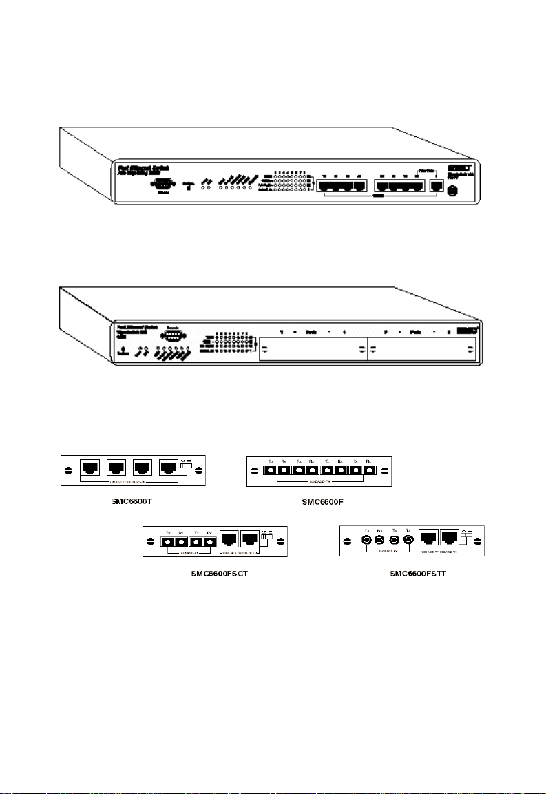
Figure 1-1. TigerSwitch 100T with 8 10BASE-T/100BASE-TX
Ports (Model SMC6608T)
Figure 1-2. TigerSwitch 100M Base Unit
(Model SMC6608M)
Figure 1-3. 4-port Fast Ethernet Modules
1-4
Page 18

ABOUT THE TIGERSWITCH 100
4-Port Fast Ethernet Modules for Model SMC6608M
The avalable slide-in modules are listed below:
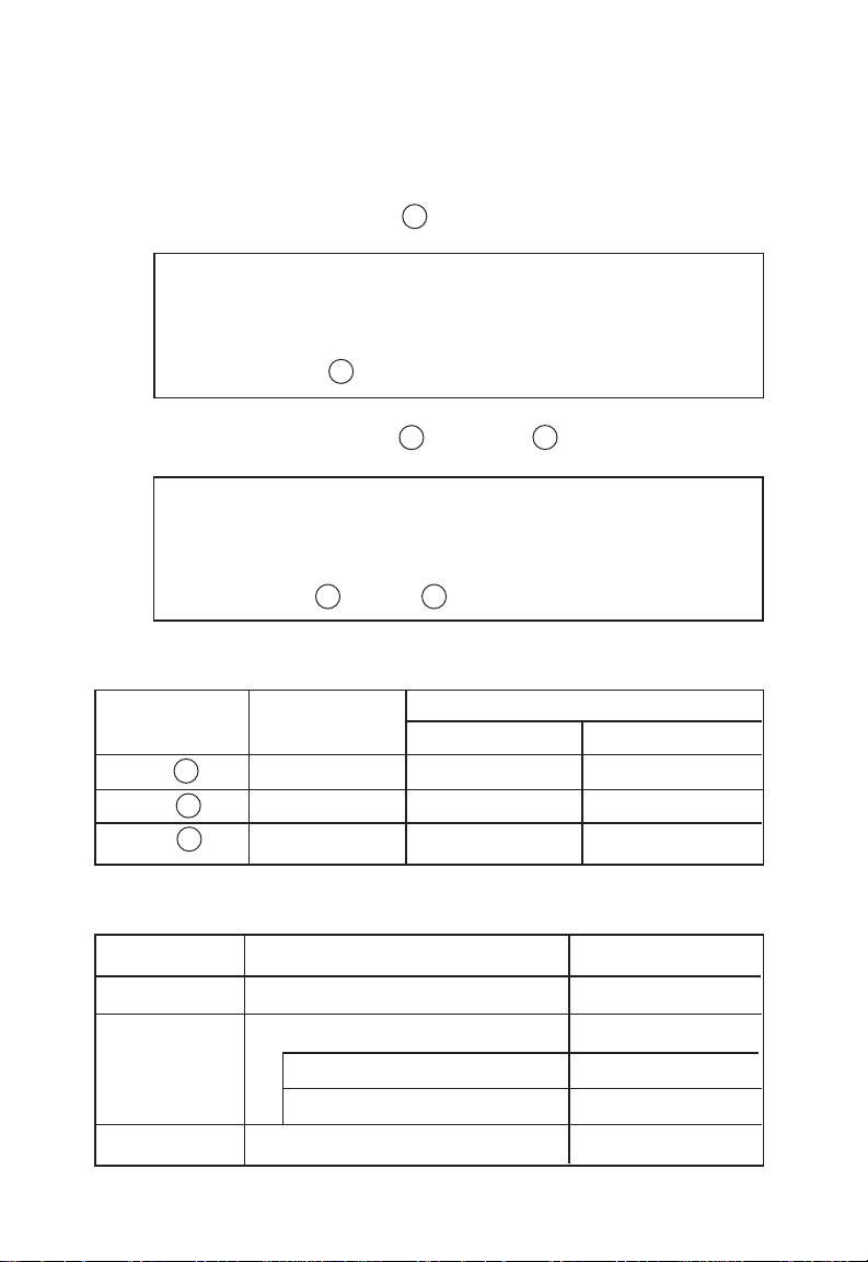
Module Ports Connectors Description
SMC6600T 1-3 RJ-45 100BASE-TX, fixed
crossover
4 RJ-45 100BASE-TX, switch-
selectable crossover
SMC6600F 1-4 SC 100BASE-FX, fiber
SMC6600FSCT 1-2 SC 100BASE-FX, fiber
3 RJ-45 100BASE-TX, fixed
crossover
4 RJ-45 100BASE-TX, switch-
selectable crossover
SMC6600FSTT 1-2 ST 100BASE-FX fiber
3 RJ-45 100BASE-TX, fixed
crossover
4 RJ-45 100BASE-TX, switch-
selectable crossover
1-5
Page 19
ABOUT THE TIGERSWITCH 100
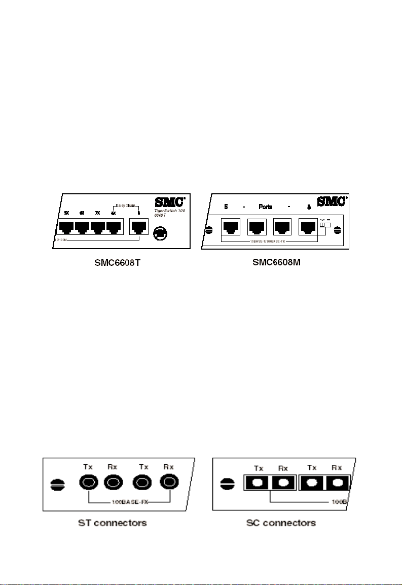
Switch Ports
10BASE-T/100BASE-TX Ports
These ports are dual-speed RJ-45 ports with built-in wiring
crossovers. Each TigerSwitch 100 equipped with 10BASE-T/
100BASE-TX ports will contain at least one straight-through
(daisy-chain) port. This port is used for straight-through cable
connections to other devices (i.e., hubs or switches) which have
ports with built-in crossovers.
Figure 1-4. 10BASE-T/100BASE-TX Ports
Each 10BASE-T/100BASE-TX port supports Auto-Negotiation, so
the optimum transmission mode (half or full duplex) and data
rate (10 Mbps or 100 Mbps) are selected automatically. If a
device connected to one of these ports does not support AutoNegotiation, the communication mode of that port can be
configured manually.
100BASE-FX Ports (SMC6608M only)
The 100BASE-FX ports are fitted with SC or ST connectors
(depending on the module) and operate exclusively at 100
Mbps. However, the transmission mode for these ports is
adjustable to full- or half-duplex and must be set manually.
Figure 1-5. 100BASE-FX Ports
1-6
Page 20
ABOUT THE TIGERSWITCH 100
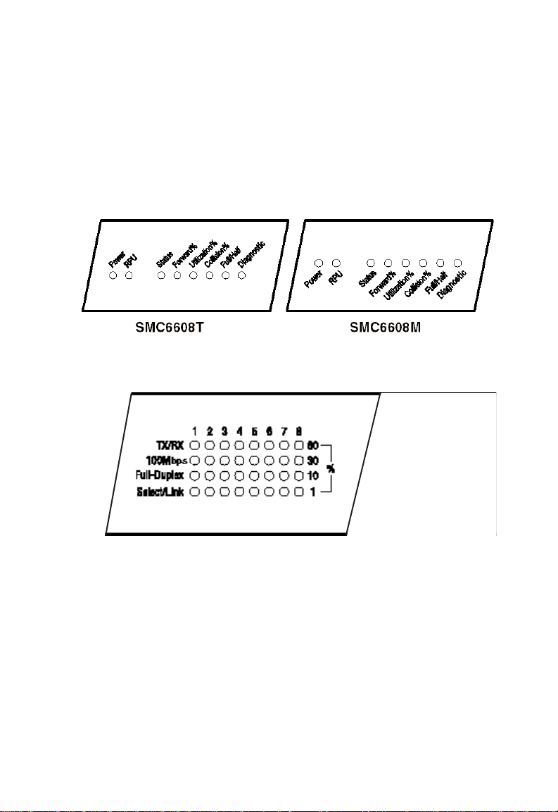
Status LEDs
The LEDs on the TigerSwitch 100 models are located on the
front panel for easy viewing. For a more complete discussion
of the front-panel LEDs, see Chapter 4, “Configuration and
Management.”
Figure 1-6. Front Panel LEDs
Figure 1-7. Front Panel LED Array
1-7
Page 21
ABOUT THE TIGERSWITCH 100
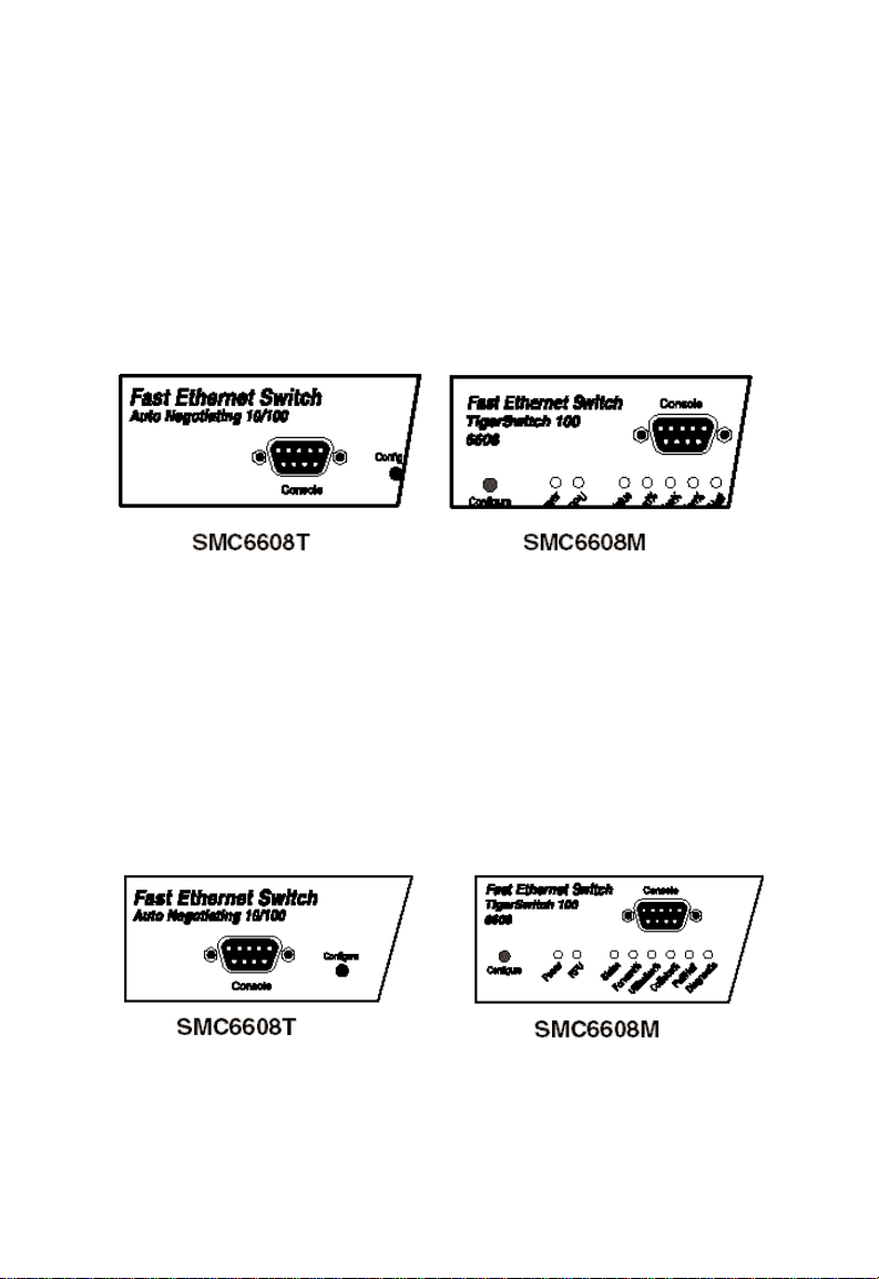
Console Port
Both TigerSwitch 100 units contain a Console port on the front
panel. This is an RS-232 serial port with a DB-9 connector. A
PC may be connected to this port for configuration and
monitoring purposes out-of band via a full-handshaking null
modem cable. (See Appendix B)
Figure 1-8. Console Port
Configure Button
The Configure button is located on the left-front panel of the
TigerSwitch 100 and is used in conjunction with the LEDs to
display a wide range of performance and status data for every
port. The Configure button can also be used to manually set
port communication modes and initiate diagnostic tests.
Figure 1-9. Configure Button
1-8
Page 22
ABOUT THE TIGERSWITCH 100
Optional Redundant Power Unit
SMC’s Redundant Power Units (RPUs) are separate devices and
each has its own power cord. These devices can supply power
to the unit in the event of a failure of the internal power supply.
The available RPUs are listed in the table below. Contact your
reseller for advice regarding the appropriate RPU for your
specific application.
Redundant Power Units (RPUs)
Order Number Description
SMC-RPUX1 Supports one SMC device
SMC-RPUX5 Supports up to 5 SMC devices
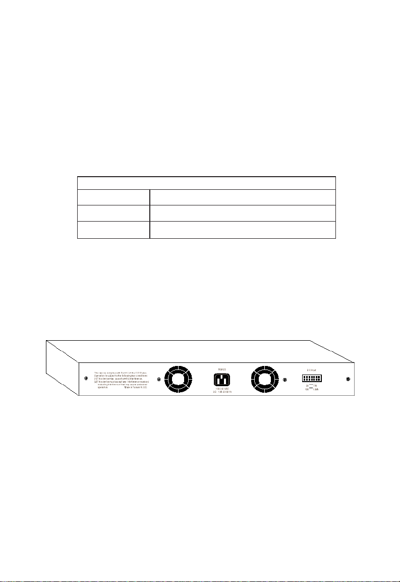
Power Supply Receptacles
There are two power receptacles on the rear-panel of each
TigerSwitch 100. The standard receptacle labeled “Power” is for
the AC power cord. The 14-pin receptacle labeled “DC Input” is
for the optional Redundant Power Unit (RPU).
Figure 1-10. Power Supply Receptacles
1-9
Page 23

ABOUT THE TIGERSWITCH 100
Switch Architecture
Switching Methods
Adaptive Cut-Through
SMC’s TigerSwitch 100 models employ a dynamic forwarding
architecture that enables them to support adaptive cut-through
frame forwarding mode. This approach allows the switch to
automatically alternate between three different switching
methods to provide the best possible performance in response
to current network conditions.
Cut-Through
Also known as “on-the-fly” switching, the cut-through switching
technique involves forwarding each data packet as soon as the
6 byte destination address in the header has been read. It does
not wait until the entire packet has been received. This
method, which takes up the least processing time, reduces the
latency of each packet to twenty microseconds (20 µsec) or less.
Cut-through switching mode is the default setting of each port
on the TigerSwitch 100.
Fragment-Free
This switching method is similar to cut-through, but it requires
that the first 64 bytes of the data packet be received before it is
forwarded. This enables the switch to discard runt packets smaller than legal size packets which are collision byproducts and effectively clean up the data stream. This method provides
the greatest benefit when the collision rate is high (e.g., when
the switch is used to interconnect several shared segments, each
having a large number of end stations.)
Store-and-Forward
In store-and-forward switching mode, the entire packet must be
received into a buffer and checked for validity before being
forwarded. This prevents errors from being propagated
throughout the network.
1-10
Page 24

ABOUT THE TIGERSWITCH 100
Spanning Tree Protocol
The TigerSwitch 100 switches support the ANSI/IEEE 802.1d
Spanning Tree Protocol. This protocol adds a level of fault
tolerance by allowing two or more redundant connections to be
created between a pair of LAN segments. When there are
multiple physical paths between segments, the protocol will
choose a single path and disable all others to ensure that only
one route exists between any two stations on the network. This
prevents the creation of network loops. However, if the chosen
path should fail for any reason, an alternate path will be
activated to maintain the connection.
The default setting for Spanning Tree Protocol is “enabled”. This
protocol may be configured (enabled or disabled) out-of-band
via the serial console port or in-band via the SNMP agent or
Telnet.
1-11
Page 25

ABOUT THE TIGERSWITCH 100
Management Options
The TigerSwitch 100 units may be managed using any one of
the following three methods:
♦ Out-of-band via the RS-232 console port
♦ In-band via Telnet
♦ In-band via any SNMP-based network management program
that includes a compiler
Serial Console Port
The switches may be managed out-of-band using a PC
connected to the console port with an RS-232 full-handshaking
null modem cable. The console port operates at 9600 baud
(default value) or 19,200 baud and can be password-protected.
A terminal application for use on the PC, such as Windows
Terminal, is also required. See Chapter 4, “Configuration and
Management,” for further information regarding out-of-band
management.
Telnet
The switches can also be managed in-band via a Telnet connection using TCP/IP protocol. The Telnet user interface is menudriven and the switch’s operating parameters can be passwordprotected. See Chapter 4, “Configuration and Management,” for
further information regarding in-band management.
SNMP
Another method by which these switches may be managed is
in-band from a workstation via an SNMP-based manager (i.e.,
SMC’s EliteView). Simple Network Management Protocol
(SNMP) is the most popular management protocol in use today.
It defines the structure of information maintained on a device
being managed and the operations used to access that
information. See Chapter 5, “SNMP Management,” for further
information regarding in-band SNMP.
1-12
Page 26

ABOUT THE TIGERSWITCH 100
Key Features and Benefits
Connectivity
• Slide-in, replaceable 4-port modules for added flexibility
(Model SMC6608M only)
• 100BASE-FX ports with SC or ST connectors (Model
SMC6608M only)
• Auto-Negotiation on 10BASE-T/100BASE-TX ports
automatically selects optimum communication mode (half or
full duplex and 10 Mbps or 100 Mbps) if this feature is
supported by the attached device; otherwise port can be
configured manually
• IEEE 802.3 Ethernet and 802.3u Fast Ethernet compliance
ensures compatibility with standards-based hubs, cards and
switches from any vendor
• Independent RJ-45 10BASE-T/100BASE-TX ports with built-in
wiring crossovers for straight-through cable connections
• 10BASE-T/100BASE-TX daisy-chain port(s) for network
device connections with straight-through cable
• Half- or full-duplex operation on each port
• Unshielded (UTP) cable supported on all RJ-45 ports:
Category 3, 4 or 5 for 10 Mbps connections and Category 5
for 100 Mbps connections
• One RS-232 serial console port for local or remote outof-band management
Performance
• Aggregate bandwidth of 1.6 Gbps
• Minimum latency of packet transmission less than 20
microseconds (cut-through switching mode)
• Transparent bridging function supported
1-13
Page 27

ABOUT THE TIGERSWITCH 100
• Operates at maximum packet filtering and forwarding rate
• Supports cut-through, store-and-forward, fragment-free and
adaptive cut-through packet transport techniques
• Routing table with over 4 K MAC address entries for attached
network nodes
• Automatically learns MAC addresses to build the routing
information database
• Fast hashing scheme quickly retrieves information from
routing table
• Filters and forwards packets at line-rate speed on all ports
• Non-blocking cross-bar switching matrix allows concurrent
operation of up to 8 LAN segments
• Back pressure Flow Control eliminates frame loss
• Automatically filters local traffic
• Transparent to all higher level protocols
Practical Management
• “At-a-Glance” LEDs for monitoring all segments
• Configure button simplifies basic configuration and
monitoring
• Console Interface for more advanced configuration and port
control
Easy Installation
• Desktop and rack-mountable (standard 19-inch rack)
• Self-diagnostics
• Automatic polarity detection and correction
1-14
Page 28

CHAPTER 2
PLANNING
Introduction to Switching . . . . . . . . . . . . . . . . 2-2
Sample Applications . . . . . . . . . . . . . . . . . . . 2-3
Collapsed Backbone . . . . . . . . . . . . . . . . . 2-3
Multiport Bridging . . . . . . . . . . . . . . . . . . . 2-4
High-Speed Switch Links . . . . . . . . . . . . . . 2-5
Collapsed Backbone with Fiber Cable . . . . 2-6
High-Speed Fiber Backbone . . . . . . . . . . . 2-7
Departmental Segment Network and
Server Farm Aggregation . . . . . . . . . . . . . . 2-8
Application Notes . . . . . . . . . . . . . . . . . . . 2-9
2-1
Page 29

PLANNING
Introduction to Switching
An Ethernet or Fast Ethernet switch allows simultaneous
transmission of multiple packets via high-bandwidth shared
memory. This means that it can partition a network more
efficiently than bridges or routers. The switch is, therefore, fast
being recognized as one of the most important building blocks
for today’s networking technology.
When performance bottlenecks are caused by congestion at the
network access point (such as the network card for a highvolume file server), the device (server, power user or switch)
can be attached directly to a switched port. And, by using fullduplex mode, the bandwidth of the dedicated segment can be
doubled to maximize throughput.*
When networks are based on repeater (hub) technology, the
maximum distance between end stations is limited. For
Ethernet, there may be up to four hubs between any pair of
stations; for Fast Ethernet, the maximum is two. This is known
as the hop count. However, a switch turns the hop count back
to zero, so subdividing the network into smaller and more
manageable segments, and linking them to the larger network
by means of a switch, removes this limitation.
A switch can be easily configured in any Ethernet or Fast
Ethernet network to significantly boost bandwidth while using
conventional cabling and network cards.
*Note: When connected to a shared collision domain (such as a hub with
multiple workstations), each switched port may operate only in halfduplex mode.
2-2
Page 30
Sample Applications
The TigerSwitch 100 is not only designed to segment your
network, but also to provide a wide range of options in setting
up network connections. Some typical applications for the
TigerSwitch 100 are described below.
Collapsed Backbone
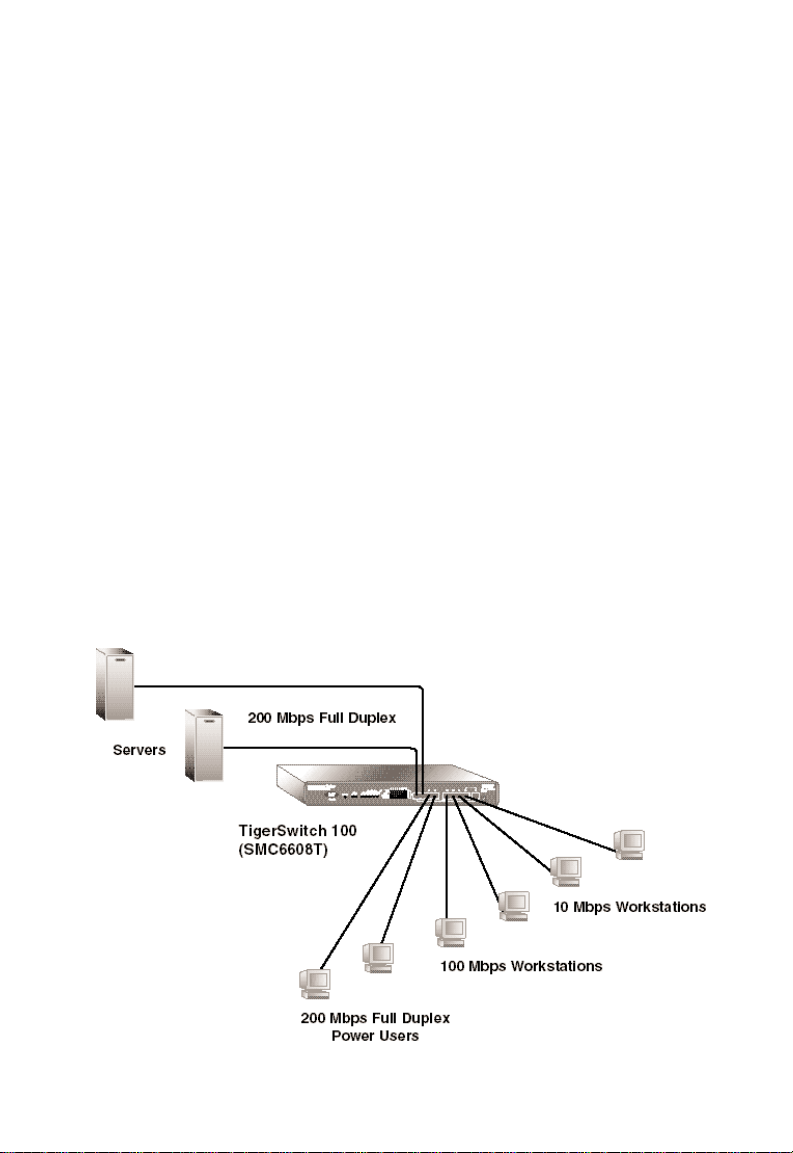
The TigerSwitch 100 is an excellent choice for Ethernet installations where significant growth is expected in the near future.
You can easily build on this basic configuration, adding direct
full-duplex connections to workstations or servers. When the
time comes for further expansion, just cascade the TigerSwitch
100 to an Ethernet or Fast Ethernet hub or switch.
In the figure below, the TigerSwitch 100T (Model SMC6608T) is
operating as a collapsed backbone for a small LAN. It provides
dedicated 10 Mbps and 100 Mbps half-duplex connections to
workstations and 200 Mbps full-duplex connections to power
users and servers.
PLANNING
Figure 2-1. Collapsed Backbone
2-3
Page 31

PLANNING
Multiport Bridging
With 8 parallel bridging ports (i.e., 8 distinct collision domains),
the TigerSwitch 100 can collapse a complex network down into
a single efficient bridged node, increasing overall bandwidth
and throughput.
In the figure below, the 10BASE-T/100BASE-TX ports on the
TigerSwitch 100T (Model SMC6608T) are providing 100 Mbps
connectivity for up to 16 segments through SMC’s TigerStack™
100 hubs. In addition, the switch is also connecting servers at
200 Mbps.
Figure 2-2. Multiple Port Bridging Connections
2-4
Page 32

Server Farm Aggregation
The advantages of mixed-media can also be easily exploited
with the TigerSwitch 100M because of the various port configurations available among its 4-port modules.
In the following example, a TigerSwitch 100M, equipped with
modules featuring 10BASE-T/100BASE-TX and 100BASE-FX
ports, is providing localized Fast Ethernet connectivity between
an expanding server farm and associated LANs.
PLANNING
Figure 2-3. Server Farm Connectivity and Expansion
2-5
Page 33
PLANNING
High-Speed Switch Links
Most common LAN implementations use a combination of
hubs, bridges and routers. The bridges and routers quickly
become bottlenecks, reducing overall network throughput.
Using switches instead of bridges and routers allows you to tie
together LAN segments and retain a cohesive LAN structure in
which any node can freely communicate with any other node in
the network.
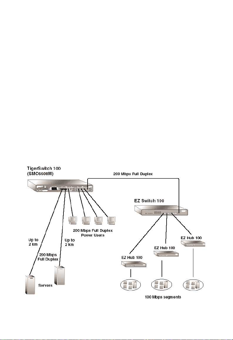
In the following figure, the TigerSwitch 100M (Model
SMC6608M) is cascaded via the 10BASE-T/100BASE-TX daisychain port to an 8-port Fast Ethernet switch, SMC’s EZ Switch™
100, forming a high-speed 200 Mbps, full-duplex backbone.
The other 10BASE-T/100BASE-TX ports are connected to power
users, and the 100BASE-FX ports are connected to servers.
Figure 2-4. Cascading to a Fast Ethernet Switch
2-6
Page 34

Collapsed Backbone with Fiber Cable
Fiber optic technology allows for a longer cable run distance
(up to 2 km in full-duplex) than any other media type. The
TigerSwitch 100M, used as a collapsed backbone to interconnect
multiple Fast Ethernet segments with fiber cable, is a convenient
way to provide direct connectivity for a wide-spread LAN.
The figure below illustrates a TigerSwitch 100M connecting
multiple segments with up to 2 km of fiber cable.
PLANNING
Figure 2-5. Collapsed Backbone Using Fiber Cable
2-7
Page 35

PLANNING
High-Speed Fiber Backbone
When maximum network reach is required, the TigerSwitch
100M (Model SMC6608M) can be used to help create a highspeed fiber backbone.
In the figure below, a TigerSwitch 100M employed as a
collapsed backbone is also part of a full-duplex, 200 Mbps fiber
backbone.
Figure 2-6. High-Speed Fiber Backbone
2-8
Page 36

Application Notes
1. Full-duplex operation only applies to point-to-point access
(e.g., when the switch is attached to a workstation, server or
another switch). When the switch is connected to a hub,
both devices must operate in half-duplex mode.
2. For network applications that actually require routers (e.g.,
interconnecting dissimilar network types), attaching switches
directly to a router can significantly improve overall network
performance.
PLANNING
2-9
Page 37

Page 38

CHAPTER 3
INSTALLATION
Selecting a Site . . . . . . . . . . . . . . . . . . . . . . . 3-2
Equipment Checklist . . . . . . . . . . . . . . . . . . . 3-3
Package Contents . . . . . . . . . . . . . . . . . . . 3-3
Required Rack-Mounting Equipment . . . . . 3-3
Mounting . . . . . . . . . . . . . . . . . . . . . . . . . . . 3-4
Mounting the Switch in a Rack . . . . . . . . . . 3-4
Mounting and Stacking the Switch on
a Flat Surface . . . . . . . . . . . . . . . . . . . . . . 3-6
Powering Up . . . . . . . . . . . . . . . . . . . . . . . . . 3-7
Connecting to a Power Source . . . . . . . . . . 3-7
Diagnostics . . . . . . . . . . . . . . . . . . . . . . . . 3-8
Making Network Connections . . . . . . . . . . . . 3-9
Connectivity Rules . . . . . . . . . . . . . . . . . . . 3-9
Twisted-Pair Cabling Guidelines . . . . . . . . . 3-11
Connecting 10BASE-T/100BASE-TX Ports . . 3-12
Fixed Crossover Ports . . . . . . . . . . . . . . 3-12
Daisy-Chain Port . . . . . . . . . . . . . . . . . . 3-12
Connecting 100BASE-FX Ports . . . . . . . . . . 3-13
3-1
Page 39

INSTALLATION
Selecting a Site
Before you start actual hardware installation, make sure you can
provide the right operating environment, including power
requirements, sufficient physical space and proximity to other
network devices. Verify the following installation requirements:
◆ The site should:
• be located in a cool, dry place, with at least 4 in. (10 cm)
of space at the front and back for ventilation
• be located out of direct sunlight and away from heat
sources or areas with a high amount of electromagnetic
interference
• allow the status LEDs to be clearly visible
◆ Make sure twisted-pair cable is always routed away from
power lines, fluorescent lighting fixtures and other sources
of electrical interference (i.e., radios, transmitters, etc.).
◆ Make sure that a separate grounded power outlet that
provides 100 to 240 VAC, 50 to 60 Hz, is within 8 feet
(2.44 m) of the unit. The switch’s power supply
automatically detects the input voltage level. And, as with
any electronic equipment, using a filter or surge suppressor
is recommended.
3-2
Page 40

Equipment Checklist
Package Contents
In addition to this user guide, the package should contain:
◆ one (1) TigerSwitch 100 switch
• Model SMC6608T (8 10BASE-T/100BASE-TX ports)
or
• Model SMC6608M (2 4-port module slots with protective
covering plates)*
◆ two (2) brackets with screws for rack mounting the unit
◆ four (4) rubber foot pads
◆ appropriate power cord(s)
◆ SMC Warranty Registration Card — be sure to complete and
return this card within 90 days
Required Rack-Mounting Equipment
Be sure to have the following equipment available when
mounting your switch in a rack:
INSTALLATION
◆ Four rack-mounting screws
◆ A screwdriver (Phillips-head or flathead, depending on the
type of screws used)
*Note: Be sure to install the module(s) you are planning to use in this unit
before you proceed with mounting the switch and applying power.
Please refer to the installation guide included with each module for
specific installation instructions.
3-3
Page 41

INSTALLATION
Mounting
The TigerSwitch 100 is suitable for desktop or rack-mount
installation. A good location is at the center of all the devices
you want to link and near a power outlet.
This switch can also be stacked with other switches on a flat
surface or in a rack. Refer to the following sections: “Mounting
the Switch in a Rack” and “Mounting and Stacking the Switch on
a Flat Surface” for a description of these methods.
Mounting the Switch in a Rack
Before rack mounting the switch, pay particular attention to the
following factors:
◆ Temperature: Since the temperature within a rack
assembly may be higher than the ambient room temperature,
check that the rack-environment temperature is within the
specified operating temperature range. (See Appendix C)
◆ Mechanical Loading: Do not place any equipment on top
of a rack-mounted unit.
◆ Circuit Overloading: Be sure that the supply circuit to the
rack assembly is not overloaded.
◆ Grounding: Rack-mounted equipment should be properly
grounded. Particular attention should be given to supply
connections other than direct connections to AC power
mains.
3-4
Page 42
INSTALLATION
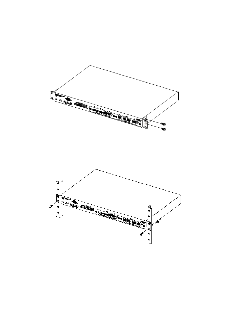
To rack mount the switch:
1. Attach the brackets to the device using the screws provided.
Figure 3-1. Attaching the Brackets
2. Mount the device in the rack, using four rack-mounting
screws.
Figure 3-2. Installing the Switch in a Rack
3-5
Page 43

INSTALLATION
Mounting and Stacking the Switch on a Flat Surface
1. Attach the four adhesive feet to the hollow spaces on the
bottom of the switch.
Figure 3-3. Attaching the Adhesive Feet
2. Set the switch on a flat surface near an AC power source,
making sure there are at least 4 inches (10 cm) of space in
the front and back for proper air flow.
3. To stack switches, repeat Step 1 for every subsequent switch
and then gently place each new switch on top of the
previous switch.
3-6
Page 44

Powering Up
Connecting to a Power Source
1. Power on the switch by plugging one end of the power cord
into the power socket on the rear panel, and the other end
into a power outlet. (See Chapter 2 for a description of the
rear-panel power receptacles)
North America: Each switch is shipped with one standard
AC line cord for North America (UL and CSA approved).
International: The international version of each switch is
shipped with AC line cords for Continental Europe and the
UK. If you need to change the line cord, you must use a
line cord set that has been approved for the receptacle type
in your country. Any cord used must be HAR certified, and
must have “HAR” stamped on the outside of the cord jacket
to comply with the CENELEC Harmonized Document HD-21.
the female receptacle must meet CEE-22 requirements and
IEC 320-030 specifications.
INSTALLATION
The switch automatically selects the setting that matches the
connected input voltage. Therefore, no additional adjustments are necessary when connecting it to any input voltage
within the range marked on the rear panel of the unit.
Caution: The 4-port modules for the TigerSwitch 100M are not
hot-swappable. If you plan to replace one of the
modules, you must disconnect the power to
prevent damaging the switch and/or the module.
2. If you have purchased a Redundant Power Unit (RPU), plug
the 14-pin connector from the RPU into the mating connector on the rear panel of the switch (See the guide supplied
with the RPU).
3-7
Page 45

INSTALLATION
3. Check to insure that the front-panel Power LED is lit. If not,
check that the power cable is correctly plugged in. (Refer to
Chapters 1 and 4 for detailed explanations of the LEDs.)
Diagnostics
Upon power up, the system performs an internal self-diagnostic
test of major switch components. If any component fails
during the test, the switch will try to complete the diagnostic
procedure. Otherwise, the system will hang.* The components
tested include:
◆ System ROM
◆ System EEPROM
◆ Ports
* Note: If the system should hang, take note of the LED indicators
and contact SMC Technical Support.
3-8
Page 46

Making Network Connections
Switches are designed to interconnect multiple segments, or
collision domains. Each segment may contain a single server or
workstation, or multiple workstations that are connected to a
hub.
Connectivity Rules
An overview of the rules for both Ethernet and Fast Ethernet
collision domains is provided below.
10 Mbps Ethernet Collision Domain
SMC 5 - 4 - 3 Rule
Between any two PCs or other stations in the same 10 Mbps
collision domain, there may be:
• up to 5 cable segments in series,
• up to 4 repeaters (hubs),
• up to 3 populated cable segments, that is, segments
attached to two or more PCs (coax networks only).*
* The remaining two segments are unpopulated; these are
known as inter-repeater links or IRLs. This distinction between
populated and unpopulated segments is significant for coax
networks only.
INSTALLATION
Maximum Cable Length
Cable Type Maximum Length
Twisted Pair, Categories 3, 4, 5 100 m (328 ft.)
3-9
Page 47
INSTALLATION
100 Mbps Fast Ethernet Collision Domain
SMC 3 - 2 Rule for Class IIRepeaters
Between any two PCs or other stations in the same 100BASE-T
collision domain, there may be:
• up to 3 link segments and
• up to 2 Class II repeaters (hubs)
SMC 2 - 1 Rule for Class I and Class II Repeaters
Between any two PCs or other stations in the same 100BASE-T
collision domain, there may be:
• up to 2 link segments and
• only 1 Class I or Class II repeater (hub)
Maximum 100BASE-T Network Diameter
Repeater Type Twisted Pair Twisted Pair/Fiber
and Number 100BASE-TX/T4 100BASE-T4/FX 100BASE-TX/FX
1 Class I 200 m (656 ft.) 231 m (757.7 ft.) 260.8 m (855.4ft.)
1 Class II 200 m (656 ft.) 304 m (997.1 ft.) 308.8 m (1012.9 ft.)
2 Class II 205 m (672.4 ft.) 236.3 m (775.1 ft.) 216.2 m (709.1 ft
.)
Maximum 100BASE-T Cable Distance
Cable Type Connecting Max. Distance
Twisted Pair Any two devices 100 m (328 ft.)
Fiber Switch to Switch, Server or PC
Half duplex 412 m (1,351.4 ft.)
Full duplex 2 km (1.24 mi.)
MII Any two devices 0.5 m (1.6 ft.)
3-10
Page 48

INSTALLATION
T wisted-Pair Cabling Guidelines
Each 10BASE-T or 100BASE-TX connection requires an
unshielded twisted-pair (UTP) cable with RJ-45 connectors at
both ends. For 10BASE-T connections, two pairs of 100 Ohm
Category 3, 4 or 5 cable are required. 100BASE-TX connections
require two pairs of certified Category 5 cable.
Every twisted-pair connection must have a wiring crossover to
transmit and receive data. For convenience, this crossover is
built into the 10BASE-T/100BASE-TX ports on the TigerSwitch
100 units*. Network cards do not have a built-in crossover, so
PCs can be connected to crossover ports with straight-through
cable. Hubs (and other switches) may have either crossover or
straight-through ports. For this reason, the type of cable used to
connect these devices to the TigerSwitch 100 is determined by
the port on the other device, as shown in the table below.
Crossover/Straight-Through Wiring Requirements
If the TigerSwitch 100 And the port on Then use...cable
port is... the other device is
Crossover (x) Straight-through Straight-through
Crossover (x) Crossover (x) Crossover
Straight-through Straight-through Crossover
Straight-through Crossover (x) Straight-through
Warning: Do not plug a phone jack connector into an
RJ-45 port. This will damage the switch. Use only
twisted-pair cables with RJ-45 connectors that conform to
FCC standards.
* Note: Each TigerSwitch 100 unit equipped with 10BASE-T/100BASE-TX ports
will also have at least one daisy-chain port that does not have a built-in
wiring crossover.
3-11
Page 49

INSTALLATION
Connecting 10BASE-T/100BASE-TX Ports
Fixed Crossover Ports
Insert the RJ-45 connector on one end of a twisted-pair cable
into an unused 10BASE-T/100BASE-TX port on the TigerSwitch
100, and the RJ-45 connector on the other end into a port on
the other device.
1. Always use straight-through cable when connecting a server
or workstation to the switch.
2. When connecting a hub, switch or other network device, the
type of cable to be used (i.e., crossover or straight-through)
depends upon the port on the device. (See “Twisted-Pair
Cabling Guidelines” in this chapter.)
3. Make sure each twisted pair cable does not exceed 100
meters (328 ft.) in length. (See “Connectivity Rules” in this
chapter.)
4. As each connection is made, the green Select/Link LED (in
the LED array) corresponding to each port will light to
indicate that the connection is valid.
Daisy-Chain Port
All TigerSwitch 100T units come with one daisy-chain (straightthrough) port. It is an alternate for port 8. Every 4-port module
for the TigerSwitch 100M with 10BASE-T/100BASE-TX ports
contains a switch-selectable daisy-chain port (See Figure 3-4).
Items 2, 3 and 4 listed in the above section also apply to the
daisy-chain port.
Figure 3-4. SwitchSelectable Daisy-Chain
Port
3-12
Page 50

Connecting 100BASE-FX Ports
TigerSwitch 100M fiber modules are equipped with either SC or
ST connectors. Connect one end of a fiber optic cable to the
appropriate fiber connector on the front panel of the
TigerSwitch 100M, and the other end to the connector on the
other device.
1. The100BASE-FX ports require 50/125 or 62.5/125 µ core
multimode fiber optic cable with an SC or ST connector at
each end.
2. Maximum fiber distance depends upon the transmission
mode. In full-duplex mode, the maximum length of a fiber
cable segment is 2 km (1.24 mi.); in half-duplex mode, it is
412 meters (0.25 mi). (See the “Maximum 100BASE-T Cable
Distance” chart on page 3-10.)
3. The TigerSwitch 100 features Flow Control to prevent frame
loss due to port saturation. If Flow Control is enabled for a
100BASE-FX port operating in half-duplex mode, the cabling
distance from that port is limited to 180 m. (See “Port
Configuration” in Chapter 4 for further information
regarding Flow Control.)
INSTALLATION
Figure 3-5. Fiber Cable Connectors
3-13
Page 51

Page 52

CHAPTER 4
CONFIGURATION AND
MANAGEMENT
Configuration Options . . . . . . . . . . . . . . . . . . 4-3
Basic Port Settings . . . . . . . . . . . . . . . . . . . . . 4-4
Advanced System Configuration . . . . . . . . . . . 4-5
Required Connections and Switch Access . . 4-5
Console Port (Out-of-Band) Connections 4-5
Remote Management via the Console Port 4-5
In-Band Connections . . . . . . . . . . . . . . . 4-6
The System Configuration Program . . . . . . 4-7
Login . . . . . . . . . . . . . . . . . . . . . . . . . . 4-7
Main Menu . . . . . . . . . . . . . . . . . . . . . . 4-8
Setting Passwords . . . . . . . . . . . . . . . . . 4-10
Console Port Configuration . . . . . . . . . . 4-11
System Parameter Configuration . . . . . . 4-12
Port Configuration . . . . . . . . . . . . . . . . . 4-14
Spanning Tree Configuration . . . . . . . . . 4-16
Virtual LAN Configuration . . . . . . . . . . . 4-18
4-1
Page 53

CONFIGURATION AND MANAGEMENT
System Monitoring . . . . . . . . . . . . . . . . . . . . . 4-19
Monitoring via the Configure Button
and LEDs . . . . . . . . . . . . . . . . . . . . . . . . . 4-19
Advanced System Monitoring . . . . . . . . . . . 4-21
System Information . . . . . . . . . . . . . . . . 4-21
Port Status . . . . . . . . . . . . . . . . . . . . . . . 4-22
Statistics . . . . . . . . . . . . . . . . . . . . . . . . 4-23
Address Table . . . . . . . . . . . . . . . . . . . . 4-25
Spanning Tree Information . . . . . . . . . . 4-26
Downloading System Software . . . . . . . . . . . . 4-28
Downloading via TFTP Protocol . . . . . . 4-28
Downloading via the Console Port . . . . . 4-29
Resetting the Switch . . . . . . . . . . . . . . . . . . . . 4-30
4-2
Page 54

CONFIGURATION AND MANAGEMENT
Configuration Options
Basic port communication modes can be configured manually
through the use of the front-panel Configure button. For more
advanced management capability, the TigerSwitch 100 provides
a menu-driven System Configuration Program which can be
accessed through the Console Interface (out-of-band) or by a
Telnet connection (in-band) over the network.
The TigerSwitch 100 also comes with an on-board management
software module based on SNMP (Simple Network Management
Protocol). This SNMP agent permits the switch to be managed
from any PC in the network using optional in-band management
software (i.e., SMC’s EliteView).
The System Configuration Program and the SNMP agent support
management functions such as:
• Enabling/Disabling of any port
• Communication Mode Configuration (Full-, Half-duplex or
Auto-Negotiation)
• Switching Mode Configuration (adaptive cut-through, cut-
through, fragment-free or store-and-forward)
• SNMP Parameter Configuration
• Virtual LAN (VLAN) Port Grouping Configuration
• Enabling/Disabling and Configuration of the Spanning Tree
Algorithm
• System Restart
4-3
Page 55

CONFIGURATION AND MANAGEMENT
Basic Port Settings
When using the Configure button to set port communication
modes:
1. Use a long press (>2 seconds) to begin function selection.
The Status LED will start to flash to indicate that functions
may be selected. Use short presses (<2 seconds) to cycle
through the status LEDs until the Full/Half LED lights. Use a
long press to initiate port communication mode selection.
After the button is released, the Full-Duplex LED for Port 1
will begin to flash.
2. Use long presses to cycle through to the chosen port. The
selection of the targeted port will be indicated by the lighting
of the Tx/Rx LED for that port.
3. Use a short press to change the communication mode for the
targeted port. The chosen mode will be indicated by the
Full-Duplex LED for the port (Lit = Full*, Unlit = Half).
4. Use a long press to enable the selection.
5. Repeat Steps 2 through 4 for each chosen port.
The default communication mode setting for all ports is AutoNegotiation, which dynamically selects either half- or full-duplex
mode and 10 or 100 Mbps operating speed in response to the
operating mode of the attached device. Auto-Negotiation can
be re-established after a manual port configuration by removing
the RJ-45 connector from the corresponding port on the switch
and then reinserting it.
*Note: Full-duplex mode can be used only for a dedicated link. When
connecting to a shared collision domain (e.g., a hub), be sure the
transmission mode is set for half-duplex mode.
4-4
Page 56

CONFIGURATION AND MANAGEMENT
Advanced System Configuration
Required Connections and Switch Access
Console Port (Out-of-Band) Connections
1. Plug the female end of a standard RS-232 null-modem cable
into the switch connector labeled “Console”. Plug the other
end of the cable into the serial connector on either a PC
(typically COM1 or COM2) running a terminal emulation
program or a VT100-compatible Terminal. See Appendix B
for Console connector pin assignments.
2. If using a PC, power up the switch and set the terminal
emulation type to VT100 and specify the PC port used (i.e.,
COM1, etc.). Then, set the communications to 8 data bits,
1 stop bit, no parity and 9600 or 19200 bps. The default
baud rate is 9600 bps. Then, open the connection to the
switch.
Remote Management via the Console Port
The Console port can also be used for switch management via a
remote PC connected through a modem:
The TigerSwitch 100 Site
Connect the Console port to the modem’s serial port using
standard cabling (e.g., not a null modem cable). Most modems
have a 25-pin port. Therefore, you will have to provide an RS232 cable with a 9-pin connector on one end (for the switch’s
Console port) and a 25-pin connector on the other. The modem
at the switch site does not have to be set because the switch
will automatically configure it to auto-answer mode. (See
Appendix B for 25-pin and 9-pin connector pinouts.)
The Remote PC site
At the remote PC site, connect the PC’s COM port (COM1, etc.)
to the modem’s serial port. Make sure the modem’s baud rate is
4-5
Page 57

CONFIGURATION AND MANAGEMENT
9600 and the AT command set is supported. Set the terminal
emulation type on the PC to VT100 and specify which PC COM
port is being used. Then, set communications to 8 data bits, 1
stop bit, no parity and the baud rate to 9600 or 19200 bps. The
default rate is 9600 bps. Then, dial into the switch. Use a
terminal emulation package to connect over the modem.
In-Band Connections
Telnet
Telnet is a common terminal emulation application used in
TCP/IP networks for remote terminal access to computer
devices. Prior to accessing the switch in-band via Telnet or
optional in-band management software, it must first be
configured with a valid IP address, subnet mask and default
gateway. This must be done via an out-of-band connection.
Once the switch’s IP parameters are configured, the menudriven System Configuration Program may be accessed from
anywhere in the network. Telnet into the switch using its
assigned IP address.
SNMP Network Connection
You can access the TigerSwitch 100’s on-board SNMP agent
from any PC in the network that is running an SNMP-based
manager (i.e., SMC’s EliteView). However, prior to accessing
the switch this way, it must first be configured with a valid IP
address, subnet mask, default gateway and community string
using an out-of-band connection.
4-6
Page 58

CONFIGURATION AND MANAGEMENT
The System Configuration Program
Login
The System Configuration Program software types and versions
appear on this screen. The default passwords for the System
Configuration Program are “admin” and “guest”. The admin
password provides administrator rights (i.e., Read/W rite access
to configuration parameters and statistical information). The
guest password provides only observer rights (i.e., Read-only
access to statistical information and no access to Configuration
or Software Download menus). Type “admin” and press
<ENTER> to open the Main Menu.
The default passwords should be changed to prevent unauthorized access. (See “Setting Passwords” later in this chapter.)
SSSSSSSS MMM MMM CCCCCCC
SS SS MMMM MMMM CC CC
SSS SSS MMM M M MMM CC CCC
SS MMM M M MMM CCC
SSSSSSSS MMM M M MMM CCC
SSS SSS MMM M M MMM CC CCC
SS SS MMM M MMM CC CC
SSSSSSSS MMMMM MMMMM CCCCCCC
SS MMM M M MMM CCC
TigerSwitch 100
(c) Copyright SMC, 1997-All rights reserved.
Hardware Main Board Version W.WW
Firmware Main Board Version X.XX
Hardware Agent Module Version Y.YY
Firmware Agent Module Version Z.ZZ
Password :
Type Password, then press <Enter>
Figure 4-1. System Configuration Program Login Screen
4-7
Page 59

CONFIGURATION AND MANAGEMENT
Main Menu
The Main Menu provides access to all the sub-menus necessary
to configure and monitor the switch.
Main Menu
Information & Statistics :
System Information... Port Status...
Statistics... Address Table...
Spanning Tree Information...
Configuration :
System Configuration... Port Configuration...
Spanning Tree Configuration
Console Configuration...
Virtual LAN Configuration...
Download & Reset :
TFTP Download... Serial Download...
Reset...
LOGOFF
SNMP Configuration...
Use cursor keys to choose item. Press <ENTER> to confirm choice.
Press <CTRL><N> to exit console.
Figure 4-2. System Configuration Program Main Menu
Main Menu Items
Information and Statistics:
System Information: Provides detailed system description.
Statistics: Shows statistics for overall switch or each port.
Spanning Tree Information: Displays Spanning Tree Protocol
parameter listing.
Port Status: Shows the operational state of each port.
Address Table: Shows the current addresses associated with
each port.
4-8
Page 60

CONFIGURATION AND MANAGEMENT
Configuration:
System Configuration: Shows basic IP setup and identifies
system by name, location and contact.
SNMP Configuration: Configures communities and trap
managers.
Password Configuration: Sets Administrator and User
passwords.
Virtual LAN Configuration: Assigns switch ports to form up to
8 independent LAN groups.
Port Configuration: Disables/enables any port; sets communication mode for any port; sets aging time for address table
entries; sets switching mode: enables/disables flow control.
Spanning Tree Configuration: Enables/disables Spanning Tree
Algorithm. Also sets Spanning Tree parameters, port
priority and path cost.
Console Configuration: Sets communication parameters for
console port.
Download & Reset:
TFTP Download: In-band download of updated firmware.
Serial Download: On-board download of updated firmware.
Reset: Resets hardware or configuration parameters, clears
MAC address table.
LOGOFF: Exits program and discontinues communications.
4-9
Page 61

CONFIGURATION AND MANAGEMENT
Setting Passwords
1. Highlight “Password Configuration” in the Main Menu and
press <ENTER>. This will access the Password Configuration
Screen (See below).
Password Configuration
Set Administrator Password
Set Normal User Password
Return to Previous Menu
Use cursor keys to choose item. Press <ENTER> to confirm choice.
Press <CTRL><N> to return to Main Menu.
Figure 4-3. Password Configuration Screen
2. Highlight “Set Administrator Password” and press
<ENTER> to password protect administrator rights
(Read/W rite privileges). Enter the default administrator password (“admin”) in the space provided. The system will then
request a new password and verification.
3. Choose set “Normal User Password” and press <ENTER>
to assign a password for Read privileges only. The system
will ask only for the new password.
After assigning passwords, you must exit the System
Configuration program (LOGOFF on the Main Menu) for the
changes to take effect. If the user does not exit the program after
setting new passwords, the interface will not be password
protected.
It is recommended that you assign an administrator password as
soon as possible to prevent unauthorized switch re-configuration. If a password is set and then forgotten, contact SMC Tech
support to regain system access.
4-10
Page 62

CONFIGURATION AND MANAGEMENT
Console Port Configuration
The communications parameters for the RS-232 port can be set
using the System Configuration Program. Figure 4-3 (below)
illustrates the factory default settings.
Console Configuration
9600
Console Time-Out (In Minutes) 5
Return to Previous Menu
Use cursor keys to choose item. Press <ENTER> to confirm choice.
Press <CTRL><N> to return to Main Menu
Figure 4-4. Console Configuration Screen
1. Highlight “Console Configuration” in the Main Menu and
press <ENTER>. This will access the Console Configuration
Screen.
2. Highlight “Console Baud Rate” to set the rate at which data
is sent between the terminal or PC and the switch. Press
<ENTER> and use the arrow keys to cycle through baud
rates of 2400, 4800, 9600 and 19200. Choose either 9600 or
19200. Press <ENTER> again to confirm the chosen rate.
3. Highlight “Console Time-Out (In Minutes)” to set the time-
out interval of the connection. Once this interval is
exceeded, the connection “times-out” and returns the user to
the Login screen. Press <ENTER> to input a value between
0* and 60 seconds. Press <ENTER> again to confirm the
chosen interval.
*Note: An entry of 0 in this field will disable the console time-out function.
4-11
Page 63

CONFIGURATION AND MANAGEMENT
System Parameter Configuration
1. Highlight “System Configuration” in the Main Menu and
press <ENTER>. This will access the System Configuration
Screen (See below).
System Configuration
System Name SMC TigerSwitch 100
System Location MIS
System Contact SMC Technical Support Dept.
Default Gateway 192.72.24.202
Subnet Mask 255.255.255.0
IP State BootP When Needed
Send Ping
Return to Previous Menu
Use cursor keys to choose item. Press <ENTER> to confirm choice.
Press <CTRL><N> to return to Main Menu
192.72.24.31
Figure 4-5. System Configuration Screen
2. Highlight “System Name” and press <ENTER> to assign a
name to identify the switch if the default entry (see above) is
not suitable. Press <ENTER> again to confirm entry.
3. Highlight “System Location” and press <ENTER> to input
the physical location of the switch. Press <ENTER> again to
confirm entry.
4. Highlight “System Contact” and press <ENTER> to specify
the party to contact in the event of a switch malfunction.
Press <ENTER> again to confirm entry.
5. Highlight “IP Address” and press <ENTER> to assign an IP
address to the switch. Press <ENTER> again to confirm
entry.
4-12
Page 64

CONFIGURATION AND MANAGEMENT
6. Highlight “Default Gateway” and press <ENTER> to set the
default gateway IP address to which the unit will send IP
packets destined for a different subnet. Press <ENTER>
again to confirm entry.
7. Highlight “Subnet Mask” and press <ENTER> to set the sub-
net mask corresponding to the assigned IP address. Press
<ENTER> again to confirm entry.
8. Highlight “IP State” and press <ENTER> to specify whether
the switch’s IP address is set by the Boot Protocol (BOOTP).
The options are:
♦ IP Disabled: Prevents the switch from processing any IP
information it receives.
♦ BOOTP When Needed: This is the default option. Will
only try to set the IP address if the address stored in the
EEPROM is 0.0.0.0
♦ BOOTP Always: Will clear any non-zero IP address from
the EEPROM to zero when the switch is booted.
9. Highlight “Send Ping” and press <ENTER> to issue an ICMP
echo request to a specified IP address. Press <ENTER> again
to send the echo request to the IP address specified. Used
to verify validity of address (i.e., that a device can be
reached).
4-13
Page 65

CONFIGURATION AND MANAGEMENT
Port Configuration
1. Highlight “Port Configuration” in the Main Menu and press
<ENTER>. This will access the Port Configuration Screen
illustrated below.
Port Configuration
Port Enabled Duplex AgingTime SwitchingMode FlowControl
1 Yes Auto 300 CT Yes
2 Yes Auto 300 CT Yes
3 Yes Auto 300 CT Yes
4 Yes Auto 300 CT Yes
5 Yes Half 300 CT Yes
6 Yes 300 CT Yes
7 Yes Auto 300 CT Yes
8 Yes Auto 300 CT Yes
Return to Previous Menu
Selecting Half or Full Duplex?
Use cursor keys to choose item. Press <ENTER> to confirm choice.
Press <CTRL><N> to return to the Main Menu
Figure 4-6. Port Configuration Screen
2. Highlight the setting under the “Enabled” column for the
chosen port and press <ENTER> to use the arrow keys to
toggle between enabling and disabling the port. Press
<ENTER> again to confirm the choice.
3. Highlight the setting under the “Duplex” column to adjust
the communication mode for the chosen port. Press
<ENTER> to use the arrow keys to cycle through Fullduplex, Half-duplex or Auto-Negotiation modes.* Press
<ENTER> again to confirm the choice.
4. Highlight the setting under the “AgingTime” column to
adjust Address Aging for the chosen port. Address Aging is
the amount of time addresses will remain in the address
table before being deleted. Press <ENTER> to input a value
between 0 and 43200 seconds. Press <ENTER> again to
confirm the chosen value.
4-14
Page 66

CONFIGURATION AND MANAGEMENT
5. Highlight the setting under the “SwitchingMode” column to
adjust the switching method for the chosen port. Press
<ENTER> to use the arrow keys to cycle through
Cut-through (CT), Store-and-forward (S&F), Adaptive cutthrough (A-CT) or Fragment-free (FgFree) modes. Press
<ENTER> again to confirm the choice.
6. Highlight the setting under the “FlowControl” column for
the chosen port and press <ENTER> to use the arrow keys to
toggle between enabling and disabling Flow Control for the
port. Flow Control allows a port that is receiving data to
signal the sender when its buffer is full, thereby ending the
transmission.** Press <ENTER> again to confirm the choice.
*Note: Auto-Negotiation will appear as a choice under the “Duplex” column
only for 10BASE-T/100BASE-TX ports. If a 10BASE-T/100BASE-TX port
is not being used, its default duplex setting will appear as Half. When
a connection is made, the port will default to Auto.
**Note: The type of flow control employed by the TigerSwitch 100 uses packet
collisions as the method by which the receiving port signals the sender.
Therefore, because collisions do not occur in full-duplex mode, Flow
Control does not operate in ports configured in full-duplex.
In addition, when Flow Control is enabled for the 100BASE-FX ports,
the allowable cable run distance is decreased from 412 m to 180 m in
half-duplex mode. (See “Connecting 100BASE-FX ports” in Chapter 3).
4-15
Page 67

CONFIGURATION AND MANAGEMENT
Spanning Tree Configuration
The Spanning Tree Protocol (STP) is used to detect and disable
network loops and to provide link back-up. It requires certain
parameter settings. The factory default settings (See Figure 4-6)
should be acceptable in most networks. To change the default
settings, proceed as follows:
Spanning Tree Configuration
Priority 32768 Maximum Message Age 20
Hello Time 2 Forward Delay 15
Port Priority Path Cost
1 128 10
2 128 10
3 128 10
4 128 10
5 128 10
6 128 10
7 128 10
8 128 10
Return to Previous Menu Take Effect Immediately
Yes
Use cursor keys to choose item. Press <ENTER> to confirm choice.
Press <CTRL><N> to return to the Main Menu
Figure 4-7. Spanning Tree Configuration Screen
1. Highlight “Spanning Tree Configuration” in the Main
Menu and press <ENTER>. This will access the configuration screen illustrated above.
2. Highlight “Spanning Tree Algorithm” and press <ENTER>
to use the arrow keys to toggle between enabling and
disabling STP. Press <ENTER> again to confirm the choice.
3. Highlight “Priority” and press <ENTER> to input a priority
value (0 to 65535) for the switch. Press <ENTER> again to
confirm the chosen value.
4-16
Page 68

CONFIGURATION AND MANAGEMENT
4. Highlight “Hello Time” and press <ENTER> to input a value
(1 to 10 seconds) for the rate at which hello frames are to be
generated. Press <ENTER> again to confirm the chosen
value.
5. Highlight “Maximum Message Age” and press <ENTER> to
input a value (6 to 40 seconds) for the amount of time any
port within the Spanning Tree network will wait before
timing out its protocol information. Press <ENTER> again to
confirm the chosen value.
6. Highlight “Forward Delay” and press <ENTER> to input a
value (4 to 30 seconds) for the amount of time any port
spends in the listening and learning states. Press <ENTER>
again to confirm the chosen value.
7. Highlight the setting under the “Path Cost” column for the
chosen port and press <ENTER> to input a value (0 to
65535) for the path cost of that port. This parameter is used
by the STP algorithm to determine the best path between
devices.* Lower values should be assigned to ports attached
to faster media. Press <ENTER> again to confirm the chosen
value.
8. Highlight the setting under the “Priority” column for the
chosen port and press <ENTER> to input a value (0 to 255)
for the priority of that port’s use in the Spanning Tree
network. If the Path Costs for all ports on a switch are the
same, the port with the highest priority (i.e., lowest value)
will be configured as an active link in the spanning tree.
Press <ENTER> again to confirm the chosen value.
9. Highlight “Take Effect Immediately” and press <ENTER> to
immediately enable the parameter changes. Press <ENTER>
again to confirm the choice.
*Note: Path Cost takes precedence over Port Priority
4-17
Page 69

CONFIGURATION AND MANAGEMENT
Virtual LAN Configuration
Switches do not inherently support broadcast domains. Use the
Virtual LAN Configuration screen (Figure 4-7) to assign any port
on the switch to up to 8 broadcast domain groups*. All ports
on the switch are assigned to a single group by default.
Port Grouping Configuration
Port Group1 Group2 Group3 Group4 Group5 Group6 Group7 Group8
1 Yes No No No No No No
2 Yes No No No No No No No
3 Yes No No No No No No No
4 Yes No No No No No No No
5 Yes No No No No No No No
6 Yes No No No No No No No
7 Yes No No No No No No No
8 Yes No No No No No No No
Return to Previous Menu
Use cursor keys to choose item. Press <ENTER> to confirm choice.
Press <CTRL><N> to return to the Main Menu
Figure 4-8. Virtual LAN Configuration Screen
1. Highlight “Virtual LAN Configuration” in the Main Menu
and press <ENTER> to access the configuration screen
illustrated above.
2. Highlight the setting under the appropriate group column for
the chosen port. Press <ENTER> to use the arrow keys to
toggle between joining the port to, or disjoining the port
from, the selected group. Press <ENTER> again to confirm
the choice.
3. Repeat Step 2 for each port, as needed.
*Note: The Spanning Tree Algorithm will be automatically disabled if two or
more groups are configured.
4-18
Page 70

CONFIGURATION AND MANAGEMENT
System Monitoring
The TigerSwitch 100 units can be monitored using either the
front-panel Configure Button and LEDs, SNMP and Telnet or the
Console Interface.
Monitoring via the Configure Button and LEDs
The Configure button may be used with the front-panel LEDs to
display various system operations characteristics. To set the
display mode using the Configure button:
1. Use a long press (>2 sec) to initiate display functions. The
“Status” LED will begin blinking upon release of the button.
(See Chapter 1, “About the TigerSwitch 100,” for an
illustration of the front-panel LEDs)
2. Once the “status” LED is blinking, use short presses (<2 sec)
of the Configure button to cycle through the various
monitoring options.
3. The function chosen will be displayed on the LED array for
each port.
The chart on the following page details the functions indicated
by the LEDs while in a lit (green) condition.
4-19
Page 71

CONFIGURATION AND MANAGEMENT
Status LEDs
LEDs Functions
Power Indicates that the switch is receiving power.
RPU Indicates that the optional Redundant Power
Unit is supplying power to the switch.
Status Indicates that the LED array is displaying status
information for each port (This is the default
display mode).
Tx/Rx (60%) Indicates that the port is
LED 100Mbps (30%) Indicates that the port is set
Array to operate at 100 Mbps.
Full-Duplex (10%) Indicates that the port is set
Select/Link (1%) Indicates a valid network
Forward % Indicates that the LED array is displaying the
percentage of all packets forwarded by each
port to another port.
Utilization % Indicates that the LED array is displaying the
percentage of LAN bandwidth being utilized
by each port.
Collision % Indicates that the LED array is displaying the
percentage of packets in collision relative to the
total number packets transmitted by each port.
Full/Half Indicates that the transmission mode for each
port may be manually set to full- or half-duplex.
Diagnostic Indicates that the unit is running internal
diagnostic tests.
transmitting or receiving
data. (Blinking)
(Unlit = 10 Mbps)
to operate in full-duplex
mode. (Unlit = half-duplex)
connection.
4-20
Page 72

CONFIGURATION AND MANAGEMENT
Advanced System Monitoring
These following display screens can be accessed through the
System Configuration Program Main Menu under the
Information and Statistics section. The following section
headings reflect the items available in this area of the Main
Menu.
System Information
This screen displays descriptive information about the switch.
System Information
System Description SMC TigerSwitch 100
Interface Description Ethernet 802.3/802.3u
System Name SMC TigerSwitch 100
System Location MIS
System Contact SMC Technical Support Dept.
System Up Time 19Day, 2HR, 41Min, 5Sec
No of Reset Since Power On 2
Return to Previous Menu
Use cursor keys to choose item. Press <ENTER> to confirm choice.
Press <CTRL><N> to return to the Main Menu
Figure 4-9. System Information Screen
System Information Screen Items
Parameter Description
System Description System’s model and name
Interface Description ANSI/IEEE standards compliance
System Name Name assigned to the switch
System Location Specifies the location where switch resides
System Contact Contact person responsible for the system
System Up Time Length of time the switch management
agent has been running
No of Reset Since Number of times the switch has been reset
Power On or the address table cleared
4-21
Page 73

CONFIGURATION AND MANAGEMENT
Port Status
This screen displays the current status of each port on the
switch.
Port Status
Port MediaType Enabled Link Speed Duplex AgTime SwhMode
FlowCntl
1 TX Yes Up 10M Half 300 A-CT Yes
2 TX Yes Down --- --- --- --- --3 TX Yes Up 10M Full 300 CT No
4 TX Yes Up 100M Half 300 A-CT Yes
5 FX Yes Up 100M Half 300 A-CT Yes
6 FX Yes Up 100M Full 300 CT No
7 TX Yes Up 100M Half 300 FgFree Yes
8 TX Yes Up 10M
Half300 S&F Yes
Figure 4-10. Port Status Screen
Port Status Screen Items
Parameter Description
Media Type Displays Port type (100BASE-FX, etc.)
Enabled Shows whether the port is enabled
Link Indicates whether a device is attached to the port
and is transmitting a link pulse signal
Speed Indicates at what speed port is operating
Duplex Indicates whether the port is running in full- or
half-duplex mode
AgTime Time (in sec.) after which unused addresses will
be discarded from address table
SwhMode Shows the method chosen for data packet
forwarding (i.e., cut-through, fragment-free, etc.)
FlowCntl Shows whether Flow Control is enabled
4-22
Page 74

CONFIGURATION AND MANAGEMENT
Statistics
This screen displays statistical information for any port or the
entire switch, depending on the display mode chosen. (See
Item 1 below)
Statistics
Time Since Last Reset Switch Statistics : 0Day, 2Hr, 5Min, 2Sec
No of Reset Switch Statistics Since Power On: 0
Local Frame Received 0 CRC Errors 0
Forwarded Frames 0 Input Queue Frame Lost 0
Learning Broadcast Frames 0 Output Queue Frame Lost 10
Long Frames 21 No of Frames in Input Queue 0
Short Frames 20 No of Frames in Output Queue 14
Collisions 0 Currently Active Stations 8
Return Refresh Screen Reset Statistics
Selecting one of ports or the switch :
Displaying all statistics counters for selected port or whole switch
Press <CTRL><X> to cancel. Use cursor keys to do selection.
Press <ENTER> to confirm choice.
Switch
Figure 4-11. Statistics Screen
This screen provides the following options:
1. Highlight “Display” and press <ENTER> to select statistical
display. Use arrow keys to cycle through display selections
(Ports 1-8 or the whole switch). Press <ENTER> to confirm
the choice.
2. Highlight “Refresh Screen” and press <ENTER> to update
all statistics counters.
3. Highlight “Reset Statistics” and press <ENTER> to clear all
statistics counters.
See the chart on the following page for a description of the
statistics displayed on this screen.
4-23
Page 75

CONFIGURATION AND MANAGEMENT
Statistics Screen Items
Item Description
Time Since Last Number of times this port (or whole switch) or
Reset of Statistics address table has been reset since power on
Local Frames Number of frames confined to this segment and
Received not forwarded
Forwarded Number of frames forwarded to another
Frames segment
Learning Broadcast Number of learning broadcast frames received
Frames on this port
Long Frames Number of times frame length has exceed
maximum allowable size (i.e., 1,518 bytes)
Short Frames Number of frames less than 64 bytes long
Collisions Number of simultaneous node transmissions
detected
CRC Errors Number of Cyclic Redundancy Check errors
Input Queue Number of frames lost because input queue is
Frame Lost full
Output Queue Number of frames lost because output queue is
Frame Lost full
No of Frames in Number of frames currently in input queue
Input Queue
No of Frames in Number of frames currently in output queue
Output Queue
Currently Active Number of entries in the address table,
Stations regardless of segment
4-24
Page 76

CONFIGURATION AND MANAGEMENT
Address Table
Address Table
Time Since Last Clear Switch Address Table: 0Day, 2Hr, 5Min, 2Sec
No of Clear Switch Address Table Since Power On: 0
Address Port Address Port
00 00 E8 C0 00 01 1 00 00 E8 C1 23 56 1
00 00 E8 C0 10 51 1 00 00 E8 00 43 22 1
00 00 E8 C5 23 47 1 00 00 E8 C0 60 01 1
Return More Search
Selecting one of ports or the switch :
Use cursor keys to choose item. Press <ENTER> to confirm choice.
Press <CTRL><N> to return to the Main Menu
Figure 4-12. Address Table Screen
This screen provides the following options:
1. Highlight “Display” and press <ENTER> to select address
table display. Use arrow keys to cycle through display
selections (Ports 1-8 or the whole switch). Press <ENTER>
to confirm the choice.
2. Highlight “More” and press <ENTER> to view more pages of
address table entries.
3. Highlight “Search” and press <ENTER> to input a particular
MAC address to search for in the address table of a selected
port or the whole switch. Press <ENTER> to start search.
4-25
Page 77

CONFIGURATION AND MANAGEMENT
Spanning Tree Information
The screen illustrated in Figure 4-12 shows a summary of the
Spanning Tree configuration. This screen is only accessible if
the Spanning Tree Protocol is enabled (See the section entitled,
“Spanning Tree Configuration” in this chapter).
Current Spanning Tree Information
Hello Time : 2 Max Message Age : 20
Forward Delay : 15 Root : 32768.00800F000001
Root Port : No_Port Root Cost : 0
Topology Change Count : 0
Time Since Last Topology Change : 0Day, 2Hr, 19Min, 41Sec
Port State DesignatedCost DesignatedBridgeID DesignatedPort
1 Disabled 128 32769.0000E8C02004 128.1
2 Blocking 128 32770.0000E8C02008 128.1
3 Listening 128 32771.0000E8C02010 128.1
4 Learning 128 32772.0000E8C02018 128.1
5 Forwarding 128 32773.0000E8C02020 128.1
6 Learning 128 32774.0000E8C02028 128.1
7 Blocking 128 32775.0000E8C02038 128.1
8 Disabled 128 32776.0000E8C02040 128.1
Return to Previous Menu
Use cursor keys to choose item. Press <ENTER> to confirm choice.
Press <CTRL><N> to return to the Main Menu
Figure 4-13. Spanning Tree Information Screen
4-26
Page 78

CONFIGURATION AND MANAGEMENT
Spanning Tree Information Screen Items
Parameter Description
Hello Time Displays the rate (in seconds) at which hello frames are
generated.
Forward Delay The amount of time (in seconds) any port in the Spanning
Tree will wait before changing states (i.e., listening to
learning, etc.).
Root Port The port on the switch that communicates with the root
device of the Spanning Tree. If the switch is the root device,
then “No_Port” will appear in this field.
Topology Change The number of times a port has entered the forwarding state
Count plus the number of times a port has changed from
forwarding to blocking.
Time Since Last The time since a port has entered the forwarding state or
Topolgy Change changed from forwarding to blocking.
Max Message Age The maximum time (in seconds) a device in the Spanning
Tree can wait for a message before reconfiguring.
Root MAC address of the root device in the Spanning Tree.
Root Cost The path cost from the switch’s root port to the root device.
State The current state of the port within the Spanning Tree:
Disabled - Port has been disabled or failed diagnostics.
Blocked - Port receives STP configuration messages,
but does not forward packets.
Listening - Port leaves Blocking state, transmits configur-
ation messages, but does not yet forward packets.
Learning - Port has transmitted configuration messages,
address table cleared, port begins learning addresses.
Forwarding - Port forwards packets and learns addresses.
Designated Cost The cost for a packet to go from this port to the root. The
slower the media, the higher the cost.
Designated Bridge The priority and MAC address of the device through which
ID this port must communicate to reach the root.
Designated Port The port on the designated bridge through which the
switch
must communicate to reach the root.
4-27
Page 79

CONFIGURATION AND MANAGEMENT
Downloading System Software
System software updates can be downloaded either in-band via
TFTP Protocol or out-of-band through the console port.
Downloading software via TFTP is substantially faster than serial
downloading through the console port. After either type of file
transfer, the switch will automatically restart.
Downloading via TFTP Protocol
In order to use this method, there must be an available TFTP
server which is IP accessible from the switch.
TFTP Download
TFTP Server Address 210.68.150.232
Download Filename XXXXXXXX.bin
Execute Network Download
Return to Previous Menu
Use cursor keys to choose item. Press <ENTER> to confirm choice.
Press <CTRL><N> to return to the Main Menu.
Figure 4-14. TFTP Download Screen
1. Highlight “TFTP Download” in the Main Menu and press
<ENTER>. This will access the TFTP Download Screen.
2. Highlight “TFTP Server Address” and press <ENTER> to
input an IP address for the TFTP server. Press <ENTER> to
confirm entry.
3. Highlight “Download Filename” and press <ENTER> to
input the file to be downloaded, if required. The file should
be a *.bin file from SMC. Press <ENTER> to confirm entry.
4-28
Page 80

CONFIGURATION AND MANAGEMENT
4. Highlight “Execute Network Download” and press
<ENTER>. The system will ask for confirmation. Press
<ENTER> to initiate download after confirmation.
Downloading via the Console Port
Software update files can be downloaded through the Console
port using any terminal emulation program that can transmit
binary files using Xmodem communications protocol. The
ASCII transfer parameters should be set for maximum
throughput.
1. Highlight “Serial Download” in the Main Menu and press
<ENTER>. This command specifies a direct upload from an
attached device via the Console port.
2. Specify Xmodem protocol and the download filename using
the terminal emulation program.
3. Initiate the download from the terminal emulation program.
4-29
Page 81

CONFIGURATION AND MANAGEMENT
Resetting the Switch
Reset
Display Diagnostics While Power-On
Reset Unit with Diagnostics
Reset Unit without Diagnostics
Clear Address Table
Reset EEprom to Factory Default Value
Use cursor keys to choose item. Press <ENTER> to confirm choice.
Press <CTRL><N> to return to the Main Menu.
Figure 4-15. Reset Screen
This screen provides the following options:
1. Highlight “Reset” in the Main Menu and press <ENTER> to
access the reset screen (Figure 4-14).
2. Highlight “Display Diagnostics While Power-On” and
press <ENTER> to enable/disable diagnostic indicators
during a reset.
3. Highlight “Reset Unit with Diagnostics” or “Reset Unit
without Diagnostics” and press <ENTER> to enable or
disable diagnostic tests, respectively, during a reset.
4. Highlight “Clear Address Table” and press <ENTER> to
clear the address table of a single port or the whole switch.
Use arrow keys to cycle through selections (Ports 1-8 or the
whole switch). Press <ENTER> to confirm the choice.
5. Highlight “Reset EEprom to Factory Default Value” and
press <ENTER> to clear all counters and restore factory
default settings for all configuration parameters. The system
will ask for confirmation. Press <ENTER> to confirm and
initiate.
4-30
Page 82

CHAPTER 5
MANAGEMENT VIA SNMP
SNMP Protocol . . . . . . . . . . . . . . . . . . . . . . . 5-2
MIB Objects . . . . . . . . . . . . . . . . . . . . . . . . . . 5-3
SNMP Parameter Configuration . . . . . . . . . . . 5-4
Assigning SNMP Agent Access Rights . . . . . 5-4
5-1
Page 83

MANAGEMENT VIA SNMP
SNMP Protocol
SNMP (Simple Network Management Protocol) is a communication protocol designed specifically for the purpose of managing
devices or other elements on a network. Network equipment
commonly managed with SNMP includes hubs, switches,
bridges, routers and host computers. SNMP is typically used to
configure these devices for proper operation in a network
environment, as well as monitor them to evaluate performance
and detect potential problems.
Managed entities supporting SNMP typically contain software
which runs locally on the device and is referred to as an agent.
The agent monitors and allows control of the functionality of
the device. A defined set of variables, referred to as objects, is
maintained by the agent and used to manage the device. These
objects are defined in a Management Information Base (MIB)
which allows for a standard presentation of information
controlled by the agent over the network.
The software used to access the information maintained by the
SNMP agent is referred to as the manager. This software
typically runs on a network-attached station and can manage a
number of agents at once. The management software uses an
MIB specification, equivalent to that which the agent maintains,
to read and write objects controlled by the agent for purposes
of configuring and monitoring the device. SNMP defines the
format of the MIB specifications and the protocol used to access
this information.
There are three main operations defined in SNMP. Operations
which read information from the managed device, such as may
be used to obtain status or statistical data, are called
GET operations. Operations that change a functional parameter on the device, such as may be used to configure security
access to the device or to initiate a self test, are referred to as
SET operations. GET and SET operations are initiated only by
5-2
Page 84

MANAGEMENT VIA SNMP
the manager software, and result in a response by the agent.
The third operation type, the TRAP, allows the agent to send an
unsolicited message to the manager. This operation is typically
used as an alert to a potential problem, or a change in device
status.
MIB Objects
A number of different MIB specifications have been defined for
managing network equipment; some are standard, others are
proprietary. SNMP-compliant devices typically support one or
more standard MIBs defined by the IETF, in the form of Request
for Comments (RFC) documents. These allow for a common
method of managing devices, such as bridges and hubs, and
network interfaces, such as Ethernet and Token Ring.
The main standard MIB, referred to as MIB II, provides an overall view of the managed agent and is supported, at least in part,
by all SNMP agents. In addition, proprietary MIB extensions are
defined by commercial vendors for managing device-specific
functions of their products.
The standards supported by the TigerSwitch 100 units include:
• RFC 1493 - Definitions of Managed Objects for Bridges
• RFC 1213 - Simple Network Management Protocol
5-3
Page 85

MANAGEMENT VIA SNMP
SNMP Parameter Configuration
In order to access the SNMP agent resident in the TigerSwitch
100 units, the switch must be configured with a valid IP address,
default gateway and subnet mask. This is accomplished
through the System Configuration Program, which can be
accessed in-band or out-of-band (See Chapter 4, “Configuration
and Management”). Additional SNMP operating parameters
may also be configured through this program.
Assigning SNMP Agent Access Rights
1. Highlight “SNMP Configuration” in the System
Configuration Program Main Menu (See Chapter 4) and press
<ENTER>. This will access the SNMP Configuration screen
(See below).
SNMP Configuration
Send Authentication Traps Yes
Community Strings....
Trap Receivers....
Use cursor keys to choose item. Press <ENTER> to confirm choice.
Press <CTRL><N> to return to the Main Menu.
Figure 5-1. SNMP Configuration Screen
2. Highlight “Send Authentication Traps” and press <ENTER>
to enable the SNMP agent to issue a trap message to
specified stations (Trap Receivers) in the event that it
receives a request containing an invalid community string.
To define valid community strings, proceed with Step 3.
Otherwise, skip to Step 5.
5-4
Page 86

MANAGEMENT VIA SNMP
3. Highlight “Community Strings” and press <ENTER>. This
will access the Community Strings screen (Figure 5-2).
Community Strings
Index Community Names Mode
1 SMC Read/Write
2 public Read
Return
Use cursor keys to choose item. Press <ENTER> to confirm choice.
Add Entry Delete Entry Change Entry Clear Entry
Press <CTRL><N> to return to the Main Menu.
Figure 5-2. Community Strings Screen
4. Highlight “Add Entry” and press <ENTER> to input a
community name and its access mode.* The community
name is the community string required for trap management
access. The access mode determines the rights available to
trap receiver stations assigned with that community string.
*Note: The community name must match the SNMP package, as well as the
switch.
5-5
Page 87

MANAGEMENT VIA SNMP
5. Highlight “Trap Receivers” in the SNMP Configuration
screen (Figure 5-1) and press <ENTER> to access the Trap
Receivers screen (Figure 5-3).
Trap Receivers
Index IP Address Community Names
1 10.148.72.66 SMC
Add Entry Delete Entry Change Entry Clear Entry
Use cursor keys to choose item. Press <ENTER> to confirm choice.
Press <CTRL><N> to return to the Main Menu.
Figure 5-3. Trap Receivers Screen
6. Highlight “Add Entry” and press <ENTER> to input an
IP Address for a receiver station and assign a community
name and index for that station. Repeat this step for each
receiver station required (up to 8).
5-6
Page 88

APPENDIX A
TROUBLESHOOTING
Switch Indicators . . . . . . . . . . . . . . . . . . . . . . A-2
Diagnostic Tests . . . . . . . . . . . . . . . . . . . . . . . A-3
System Diagnostic Tests . . . . . . . . . . . . . . . A-3
Port Diagnostic Tests . . . . . . . . . . . . . . . . . A-4
System Diagnostics . . . . . . . . . . . . . . . . . . . . A-4
Power and Cooling Problems . . . . . . . . . . . A-4
Installation . . . . . . . . . . . . . . . . . . . . . . . . A-4
Communication Mode . . . . . . . . . . . . . . . . A-5
Cabling . . . . . . . . . . . . . . . . . . . . . . . . . . . A-5
Network Cards . . . . . . . . . . . . . . . . . . . . . A-5
Physical Configuration . . . . . . . . . . . . . . . . A-5
Management Interface . . . . . . . . . . . . . . . . A-6
Terminal Emulation . . . . . . . . . . . . . . . . A-6
Telnet . . . . . . . . . . . . . . . . . . . . . . . . . . A-6
System Integrity . . . . . . . . . . . . . . . . . . . . . A-7
A-1
Page 89

TROUBLESHOOTING
Switch Indicators
The LED indicators on TigerSwitch 100 can be of assistance in
identifying problems. Some common problems and possible
solutions are described below.
Symptom: Link LED does not light up (green) after making a
connection.
Cause: Network interface (e.g., network card on the
attached device), network cable or switch port may
be defective, 4-port module (Model SMC6608M) is
not properly seated.
Solution: Verify that the switch and attached device are
powered on. Be sure the cable is plugged into
both the switch and corresponding device. Verify
that the proper cable type is used and its length
does not exceed specified limits (100 m or 328 ft.).
Check the network card and cable connections for
possible defects. Replace the defective card or
cable, if necessary. If applicable, verify that the
4-port module is properly seated. Re-install the
module, if necessary.
Symptom: Power LED does not light up (green) after power
on.
Cause: Defective power outlet, power cord or internal
power supply.
Solution: Check the power outlet by plugging in another
device that is functioning properly. Check the
power cord with another device. If these
measures fail to resolve the problem, contact
SMC Technical Support for assistance.
A-2
Page 90

TROUBLESHOOTING
Diagnostic Tests
Upon power-up, the TigerSwitch 100 units perform selfdiagnostic tests (See Chapter 3). Diagnostic tests similar to
those performed on power-up can be run using the Configure
button:
1. Use a long press (>2 seconds) to begin function selection.
The Status LED will start to flash to indicate that functions
may be selected. Use short presses (<2 seconds) to cycle
through the status LEDs until the Diagnostic LED lights. Use
a long press to initiate diagnostic tests.
System Diagnostic Tests
The diagnostic test sequence is performed in two stages. The
first stage is the system diagnostic test. The following table
details system level failures, which are indicated in the
Select/Link row of the LED array:
System Failures
Component Failure LED Array Indicator Column
System ROM 1
System RAM 2
System EEPROM 3
A-3
Page 91

TROUBLESHOOTING
Port Diagnostic Tests
Port Diagnostic Tests, the second diagnostic test phase, check
each port. The following table details port failures, which are
indicated in the column of the LED array corresponding to the
malfunctioning port:
Port Failures
Test Failure LED Array Row
Output Queue RAM Test Tx/Rx
Input Queue RAM Test 100Mbps
Routing Table Test Full-Duplex
Port IC Test Select/Link
System Diagnostics
Power and Cooling Problems
If the Power LED does not turn on when the power cord is
plugged in, you may have a problem with the power outlet,
power cord or internal power supply as explained in the
previous section. However, if the unit powers off after running
for a while, check for loose power connections, power losses or
surges at the power outlet, and verify that the fan on back of
the unit is unobstructed and running prior to shutdown. If you
still cannot isolate the problem, then the internal power supply
may be defective. In this case, contact SMC Technical Support
for assistance.
Installation
Verify that all system components have been properly installed.
If one or more components appear to be malfunctioning (e.g.,
the power cord or network cabling), test them in an alternate
environment where you are sure that all the other components
are functioning properly.
A-4
Page 92

TROUBLESHOOTING
Communication Mode
The communication mode of each port (half or full duplex and
10 Mbps or 100 Mbps) must be identical to the mode of the
attached device. Verify that each port is set to the same
communication modes used by the attached device. Each
100BASE-FX port must be configured for half- or full-duplex
operation. For each 10BASE-T/100BASE-TX port, the
communication mode is configured automatically via AutoNegotiation. However, if the attached device does not support
Auto-Negotiation, then you must configure the port manually.
(See Chapter 4, “Configuration and Management”, for port
configuration instructions.)
Cabling
Verify that the cabling type is correct. Be sure all cable
connectors are securely seated in the required ports. Also
check to be sure you are using the proper cable type: straightthrough or crossover. Use Category 5 twisted-pair cable for
100BASE-TX connections and Category 3, 4 or 5 cable for
10BASE-T connections. Use 62.5/125 micron core multimode
fiber cable for 100BASE-FX connections.
Make sure all devices are connected to the network. Equipment
may have been disconnected unintentionally.
Network Cards
Make sure the network interface hardware and software drivers
for the attached devices are functioning properly. Check the
network cards and associated drivers used in any attached
workstation or server.
Physical Configuration
If problems occur after altering the network configuration,
restore the original connections, and try to track the problems
A-5
Page 93

TROUBLESHOOTING
down by implementing the new changes, one step at a time.
Ensure that cable distances and other physical aspects of the
installation comply with recommendations. (See “Making
Network Connections” in Chapter 3.)
Management Interface
Terminal Emulation
If the terminal attached to the console port is not operating
properly, check that:
1. the attached terminal or terminal emulator is set to VT100
2. you are using the correct cable type (See Chapter 4,
“Configuration and Management”) and that it is properly
connected.
3. the console is configured properly (8 data bits, 1 stop bit, no
parity and 9600 or 19200 bps).
4. if you are using terminal emulation, there are no IRQ
conflicts.(i.e., Make sure device drivers are not using the
same IRQ required to run the COM port).
Telnet
If you have trouble establishing a link to the System
Configuration Program using Telnet:
1. Check to make sure the network connection is valid.
2. Verify that the correct IP address for the switch has been
entered at the Telnet location.
3. Make sure the port on the switch through which you are
trying to establish a Telnet connection is enabled. (See
Chapter 4, “Configuration and Management”)
4. Check the cabling between the Telnet site and the switch.
A-6
Page 94

TROUBLESHOOTING
System Integrity
As a last resort, verify the integrity of the switch with a poweron reset (See Chapter 4, “Configuration and Management”). If
the problem still persists and you have completed all the
preceding diagnoses, contact SMC Technical Support for
further assistance. Be sure to check the Login Screen
(Figure 4-1.) for the version of the System Configuration
Program (Chapter 4) installed on your TigerSwitch 100. Keep
this information close at hand when you contact SMC Technical
Support.
A-7
Page 95

Page 96

APPENDIX B
PIN ASSIGNMENTS
RJ-45 Pin Assignments . . . . . . . . . . . . . . . . . . B-2
Straight-through Wiring . . . . . . . . . . . . . . . B-3
Crossover Wiring . . . . . . . . . . . . . . . . . . . . B-3
Console Port Pin Assignments . . . . . . . . . . . . B-4
B-1
Page 97
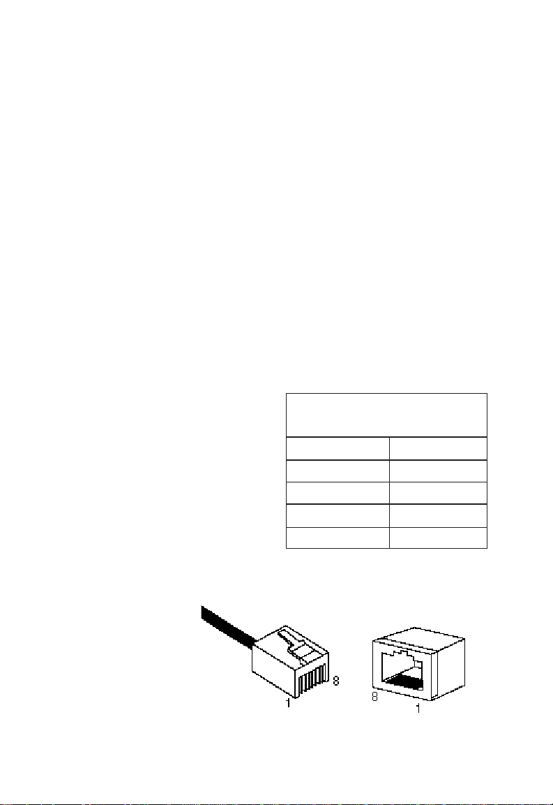
PIN ASSIGNMENTS
RJ-45 Pin Assignments
Caution: Regulations regarding the connection of equipment
to telephone networks vary from country to country.
Check with your local telephone network supplier
before using existing telephone wiring.
An Ethernet twisted-pair link segment requires two pairs of
wires—Category 3, 4 or 5 for 10 Mbps connections and
Category 5 for 100 Mbps connections. Each wire pair is identified by two different colors. For example, one wire might be
brown and the other, brown with white stripes.
Caution: Each wire pair must be attached to the RJ-45 connec-
tors in a specific orientation. (See “Twisted-Pair
Cabling Guidelines” in Chapter 3 for an explanation.)
Each twisted-pair link
segment must have an RJ-45
connector attached to both
ends. According to the IEEE
specifications, pins 1 and 2
are used for transmitting
data, and pins 3 and 6 for
receiving data.
*The “+” and “-” signs are used to
represent the polarity of the wires that make up each wire pair.
RJ-45 Pin Assignments
Pin Number Assignment*
1 Tx+
2 Tx3 Rx+
6 Rx-
Note how the
pins are numbered. Be sure
to hold the connectors in the
same orientation
when attaching
the wires to the
pins.
B-2
Figure B-1. RJ-45 Connector Pin Numbers
Page 98

PIN ASSIGNMENTS
Straight-Through Wiring
If the twisted-pair link segment is to join two ports and only
one of the ports has an internal crossover, the two pairs of
wires must be straight-through.
Straight-Through RJ-45 Pin Assignments
End 1 End 2
1 (Tx+) 1 (Tx+)
2 (Tx-) 2 (Tx-)
3 (Rx+) 3 (Rx+)
6 (Rx-) 6 (Rx-)
Crossover Wiring
If the twisted-pair link segment is to join two ports and either
both ports are labeled with an “x” or neither port is labeled
with an “x,” a crossover must be implemented in the wiring.
Crossover RJ-45 Pin Assignments
End 1 End 2
1 (Tx+) 3 (Rx+)
2 (Tx-) 6 (Rx-)
3 (Rx+) 1 (Tx+)
6 (Rx-) 2 (Tx-)
B-3
Page 99
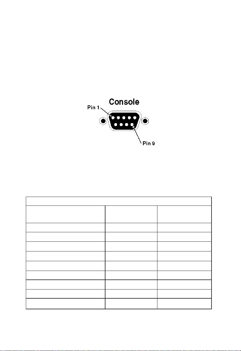
PIN ASSIGNMENTS
Console Port Pin Assignments
The DB-9 serial console port on the front-panel is used to
connect the switch to a console device, either directly or
remotely. The pin assignments for connection to another DB-9
port or a DB-25 port are provided below and on the following
pages.
Figure B-2. DB-9 Console Port Pin Numbers
Note: Any cable connected to the Console port must be
shielded to comply with FCC emissions regulations and
with requirements of other regulatory agencies in
various parts of the world.
DB-9 Pin Assignments
Signal DB-9* Pin No. DB-25 Pin No.
DTE DCE
DCD (Data Carrier Detected) 1 8
RxD (Received Data) 2 3
TxD (Transmitted Data) 3 2
DTR (Data Terminal Ready) 4 20
SG (Signal Ground) 5 7
DSR (Data Set Ready) 6 6
RTS (Request to Send) 7 4
CTS (Clear to Send) 8 5
RI (Ring Indicator) 9 22
B-4
* DB-9 port on PC or TigerSwitch 100.
Page 100

PIN ASSIGNMENTS
Console Port to 9-Pin COM Port on PC
Switch Port PC Port
DB-9 Pin No. Signal DB-9 Pin No.
1 (DCD) DCD 1
2 (RXD) TXD 3
3 (TXD) RXD 2
4 (DTR) DSR 6
5 (SGND) SGND 5
6 (DSR) DTR 4
7 (RTS) CTS 8
8 (CTS) RTS 7
9 (RI) RI 9
Console Port to 25-Pin DCE Port on Modem
Switch Port 25-Pin Modem Port
DB-9 Pin No. Signal DCE Pin No.
1 DCD 8
2 RXD 3
3 TXD 2
4 DTR 20
5 SGND 7
6 DSR 6
7 RTS 4
8 CTS 5
9RI22
B-5
 Loading...