

Page 1

USER GUIDE
SMC2890W-AG /
SMC2891W-AG
Elite Connect™
802.11a/g Outdoor Enterprise Access Point
Page 2

EliteConnect™ SMC2890W-AG and
SMC2891W-AG Universal 2.4GHz/
5GHz Wireless Dual-Band Outdoor
Access Point
The easy way to make all your network connections
20 Mason,
Irvine, CA 92618
Phone: (949) 679-8000
February 2007
Revision Number: R01
F1.0.0.1
Page 3

Copyright
Information furnished by SMC Networks, Inc. (SMC) is believed to be accurate and reliable.
However, no responsibility is assumed by SMC for its use, nor for any infringements of patents
or other rights of third parties which may result from its use. No license is granted by
implication or otherwise under any patent or patent rights of SMC. SMC reserves the right to
change specifications at any time without notice.
Copyright © 2005 by
SMC Networks, Inc.
20 Mason
Irvine, CA 92618
All rights reserved.
Trademarks:
SMC is a registered trademark; and EliteConnect is a trademark of SMC Networks, Inc. Other
product and company names are trademarks or registered trademarks of their respective
holders.
Page 4

Compliances
Federal Communication Commission Interference Statement
This equipment has been tested and found to comply with the limits for a Class B digital
device, pursuant to Part 15 of the FCC Rules. These limits are designed to provide
reasonable protection against harmful interference in a residential installation. This
equipment generates, uses and can radiate radio frequency energy and, if not installed
and used in accordance with the instructions, may cause harmful interference to radio
communications. However, there is no guarantee that interference will not occur in a
particular installation. If this equipment does cause harmful interference to radio or
television reception, which can be determined by turning the equipment off and on, the
user is encouraged to try to correct the interference by one of the following measures:
• Reorient or relocate the receiving antenna
• Increase the separation between the equipment and receiver
• Connect the equipment into an outlet on a circuit different from that to which the receiver
is connected
• Consult the dealer or an experienced radio/TV technician for help
FCC Caution: Any changes or modifications not expressly approved by the party
responsible for compliance could void the user’s authority to operate this equipment. This
device complies with Part 15 of the FCC Rules. Operation is subject to the following two
conditions: (1) This device may not cause harmful interference, and (2) this device must
accept any interference received, including interference that may cause undesired
operation.
IMPORTANT NOTE: FCC Radiation Exposure Statement
This equipment complies with FCC radiation exposure limits set forth for an uncontrolled
environment. This equipment should be installed and operated with a minimum distance
of 20 centimeters (8 inches) between the radiator and your body. This transmitter must
not be co-located or operating in conjunction with any other antenna or transmitter.
Wireless 5 GHz Band Statement:
As the access point can operate in the 5150-5250 MHz frequency band it is limited by the
FCC, Industry Canada and some other countries to indoor use only so as to reduce the
potential for harmful interference to co-channel Mobile Satellite systems.
High power radars are allocated as primary users (meaning they have priority) of the
5250-5350 MHz and 5650-5850 MHz bands. These radars could cause interference and/
or damage to the access point.
i
Page 5

VCCI Notice
This is a class A product based on the standard of the Voluntary Control Council for
Interference by Information Technology Equipment (VCCI). If this equipment is used in a
domestic environment, radio disturbance may arise. When such trouble occurs, the user
may be required to take corrective actions.
EC Conformance Declaration
Marking by the above symbol indicates compliance with the Essential Requirements of
the R&TTE Directive of the European Union (1999/5/EC). This equipment meets the
following conformance standards:
• EN 60950 (IEC 60950) - Product Safety
• EN 301 893 - Technical requirements for 5 GHz radio equipment
• EN 300 328 - Technical requirements for 2.4 GHz radio equipment
• EN 301 489-1 / EN 301 489-17 - EMC requirements for radio equipment
Countries of Operation & Conditions of Use in the European
Community
This device is intended to be operated in all countries of the European Community.
Requirements for indoor vs. outdoor operation, license requirements and allowed
channels of operation apply in some countries as described below:
Note:
The user must use the configuration utility provided with this product to ensure the
channels of operation are in conformance with the spectrum usage rules for
European Community countries as described below.
• This device requires that the user or installer properly enter the current country of
operation in the command line interface as described in the user guide, before operating
this device.
• This device will automatically limit the allowable channels determined by the current
country of operation. Incorrectly entering the country of operation may result in illegal
operation and may cause harmful interference to other system. The user is obligated to
ensure the device is operating according to the channel limitations, indoor/outdoor
restrictions and license requirements for each European Community country as
described in this document.
ii
Page 6

• This device employs a radar detection feature required for European Community
operation in the 5 GHz band. This feature is automatically enabled when the country of
operation is correctly configured for any European Community country. The presence of
nearby radar operation may result in temporary interruption of operation of this device.
The radar detection feature will automatically restart operation on a channel free of
radar.
• The 5 GHz Turbo Mode feature is not allowed for operation in any European Community
country. The current setting for this feature is found in the 5 GHz 802.11a Radio Settings
Window as described in the user guide.
• The 5 GHz radio's Auto Channel Select setting described in the user guide must always
remain enabled to ensure that automatic 5 GHz channel selection complies with
European requirements. The current setting for this feature is found in the 5 GHz
802.11a Radio Settings Window as described in the user guide.
• This device may be operated indoors or outdoors in all countries of the European
Community using the 2.4 GHz band: Channels 1 - 13, except where noted below.
- In Italy the end-user must apply for a license from the national spectrum authority to
operate this device outdoors.
- In Belgium outdoor operation is only permitted using the 2.46 - 2.4835 GHz band:
Channel 13.
- In France outdoor operation is only permitted using the 2.4 - 2.454 GHz band:
Channels 1 - 7
Operation Using 5 GHz Channels in the European Community
The user/installer must use the provided configuration utility to check the current channel
of operation and make necessary configuration changes to ensure operation occurs in
conformance with European National spectrum usage laws as described below and
elsewhere in this document.
Allowed 5GHz Channels in Each European Community Country
Allowed Frequency Bands Allowed Channel Numbers Countries
5.15 - 5.25 GHz* 36, 40, 44, 48 Austria, Belgium
5.15 - 5.35 GHz* 36, 40, 44, 48, 52, 56, 60, 64 France, Switzerland,
Liechtenstein
5.15 - 5.35* & 5.470 - 5.725
GHz
36, 40, 44, 48, 52, 56, 60, 64,
100, 104, 108, 112, 116, 120,
124, 128, 132, 136, 140
Denmark, Finland,
Germany, Iceland,
Ireland, Italy,
Luxembourg,
Netherlands, Norway,
Portugal, Spain,
Sweden, U.K.
iii
Page 7

Allowed 5GHz Channels in Each European Community Country
Allowed Frequency Bands Allowed Channel Numbers Countries
5 GHz Operation Not Allowed None Greece
* Outdoor operation is not allowed using 5.15-5.35 GHz bands (Channels 36 - 64).
Channels 36 - 64 are currently not available for use.
Safety Compliance
Power Cord Safety
Please read the following safety information carefully before installing the device:
Warning:
• The unit must be connected to an earthed (grounded) outlet to comply with international
• Do not connect the unit to an A.C. outlet (power supply) without an earth (ground)
• The appliance coupler (the connector to the unit and not the wall plug) must have a
• The socket outlet must be near to the unit and easily accessible. You can only remove
• This unit operates under SELV (Safety Extra Low Voltage) conditions according to IEC
France and Peru only
This unit cannot be powered from IT
must be powered by 230 V (2P+T) via an isolation transformer ratio 1:1, with the
secondary connection point labelled Neutral, connected directly to earth (ground).
†
Impédance à la terre
Important! Before making connections, make sure you have the correct cord set. Check
it (read the label on the cable) against the following:
Installation and removal of the unit must be carried out by qualified personnel
only.
safety standards.
connection.
configuration for mating with an EN 60320/IEC 320 appliance inlet.
power from the unit by disconnecting the power cord from the outlet.
60950. The conditions are only maintained if the equipment to which it is connected also
operates under SELV conditions.
†
supplies. If your supplies are of IT type, this unit
iv
Page 8

Power Cord Set
U.S.A. and
Canada
Denmark The supply plug must comply with Section 107-2-D1, Standard
Switzerland The supply plug must comply with SEV/ASE 1011.
U.K. The supply plug must comply with BS1363 (3-pin 13 A) and be
Europe The supply plug must comply with CEE7/7 (“SCHUKO”).
Veuillez lire à fond l'information de la sécurité suivante avant d'installer l’appareil:
AVERTISSEMENT: L’installation et la dépose de ce groupe doivent être confiés à un
personnel qualifié.
• Ne branchez pas votre appareil sur une prise secteur (alimentation électrique) lorsqu'il
n'y a pas de connexion de mise à la terre (mise à la masse).
• Vous devez raccorder ce groupe à une sortie mise à la terre (mise à la masse) afin de
respecter les normes internationales de sécurité.
• Le coupleur d’appareil (le connecteur du groupe et non pas la prise murale) doit
respecter une configuration qui permet un branchement sur une entrée d’appareil EN
60320/IEC 320.
• La prise secteur doit se trouver à proximité de l’appareil et son accès doit être facile.
Vous ne pouvez mettre l’appareil hors circuit qu’en débranchant son cordon électrique
au niveau de cette prise.
The cord set must be UL-approved and CSA certified.
The minimum specifications for the flexible cord are:
- No. 18 AWG - not longer than 2 meters, or 16 AWG.
- Type SV or SJ
- 3-conductor
The cord set must have a rated current capacity of at least 10 A
The attachment plug must be an earth-grounding type with
NEMA 5-15P (15 A, 125 V) or NEMA 6-15P (15 A, 250 V)
configuration.
DK2-1a or DK2-5a.
fitted with a 5 A fuse which complies with BS1362.
The mains cord must be <HAR> or <BASEC> marked and be of
type HO3VVF3GO.75 (minimum).
The mains cord must be <HAR> or <BASEC> marked and be of
type HO3VVF3GO.75 (minimum).
IEC-320 receptacle.
v
Page 9

• L’appareil fonctionne à une tension extrêmement basse de sécurité qui est conforme à
la norme IEC 60950. Ces conditions ne sont maintenues que si l’équipement auquel il
est raccordé fonctionne dans les mêmes conditions.
France et Pérou uniquement:
Ce groupe ne peut pas être alimenté par un dispositif à impédance à la terre. Si vos
alimentations sont du type impédance à la terre, ce groupe doit être alimenté par une
tension de 230 V (2 P+T) par le biais d’un transformateur d’isolement à rapport 1:1, avec
un point secondaire de connexion portant l’appellation Neutre et avec raccordement
direct à la terre (masse).
Cordon électrique - Il doit être agréé dans le pays d’utilisation
Etats-Unis et
Canada:
Danemark: La prise mâle d’alimentation doit respecter la section 107-2 D1
Suisse: La prise mâle d’alimentation doit respecter la norme SEV/ASE
Europe La prise secteur doit être conforme aux normes CEE 7/7
Le cordon doit avoir reçu l’homologation des UL et un certificat
de la CSA.
Les spécifications minimales pour un cable flexible sont AWG
No. 18, ouAWG No. 16 pour un cable de longueur inférieure à 2
mètres.
- type SV ou SJ
- 3 conducteurs
Le cordon doit être en mesure d’acheminer un courant nominal
d’au moins 10 A.
La prise femelle de branchement doit être du type à mise à la
terre (mise à la masse) et respecter la configuration NEMA
5-15P (15 A, 125 V) ou NEMA 6-15P (15 A, 250 V).
de la norme DK2 1a ou DK2 5a.
1011.
(“SCHUKO”)
LE cordon secteur doit porter la mention <HAR> ou <BASEC> et
doit être de type HO3VVF3GO.75 (minimum).
vi
Page 10

Bitte unbedingt vor dem Einbauen des Geräts di e folgenden
Sicherheitsanweisungen durchlesen
WARNUNG: Die Installation und der Ausbau des Geräts darf nur durch Fachpersonal
erfolgen.
• Das Gerät sollte nicht an eine ungeerdete Wechselstromsteckdose angeschlossen
werden.
• Das Gerät muß an eine geerdete Steckdose angeschlossen werden, welche die
internationalen Sicherheitsnormen erfüllt.
• Der Gerätestecker (der Anschluß an das Gerät, nicht der Wandsteckdosenstecker) muß
einen gemäß EN 60320/IEC 320 konfigurierten Geräteeingang haben.
• Die Netzsteckdose muß in der Nähe des Geräts und leicht zugänglich sein. Die
Stromversorgung des Geräts kann nur durch Herausziehen des Gerätenetzkabels aus
der Netzsteckdose unterbrochen werden.
• Der Betrieb dieses Geräts erfolgt unter den SELV-Bedingungen
(Sicherheitskleinstspannung) gemäß IEC 60950. Diese Bedingungen sind nur gegeben,
wenn auch die an das Gerät angeschlossenen Geräte unter SELV-Bedingungen
betrieben werden.
(Germany):
vii
Page 11

Stromkabel. Dies muss von dem Land, in dem es benutzt wird geprüft werden:
U.S.A und Canada Der Cord muß das UL gepruft und war das CSA beglaubigt.
Das Minimum spezifikation fur der Cord sind:
- Nu. 18 AWG - nicht mehr als 2 meter, oder 16 AWG.
- Der typ SV oder SJ
- 3-Leiter
Der Cord muß haben eine strombelastbarkeit aus wenigstens
10 A
Dieser Stromstecker muß hat einer erdschluss mit der typ
NEMA 5-15P (15A, 125V) oder NEMA 6-15P (15A, 250V)
konfiguration.
Danemark Dieser Stromstecker muß die ebene 107-2-D1, der standard
Schweiz Dieser Stromstecker muß die SEV/ASE 1011Bestimmungen
Europe Das Netzkabel muß vom Typ HO3VVF3GO.75
DK2-1a oder DK2-5a Bestimmungen einhalten.
einhalten.
(Mindestanforderung) sein und die Aufschrift <HAR> oder
<BASEC> tragen.
Der Netzstecker muß die Norm CEE 7/7 erfüllen (”SCHUKO”).
viii
Page 12

Table of Contents
Chapter 1: Introduction 1-1
Radio Charac teristics 1-1
Package Checklist 1-2
Hardware Description 1-2
LED Indicat ors 1-3
Integrated High-Gain Antenna 1-5
External Antenna Options 1-5
Ethernet Port 1-6
Power Injector Module 1-6
Grounding Po int 1-7
Water Tight Test Point 1-7
Wall- and Pole-Mounting Bracket Kit 1-7
System Configuration 1-8
Features and Benefits 1-8
Chapter 2: Network Configuration 2-1
Access Point Topologi es 2-1
Infrastructure Wireless LAN 2-2
Infrastructure Wireless LAN for Roaming Wireless PCs 2-3
Bridge Link Topologies 2-4
Point-to-Point Configuration 2-4
Point-to-Multipoint Configuration 2-5
Chapter 3: Bridge Link Planning 3-1
Data Rates 3-1
Radio Path Planning 3-1
Antenna Height 3-2
Antenna Position and Orientation 3-4
Radio Interference 3-5
Weather Conditions 3-5
Ethernet C abling 3-5
Grounding 3-6
Chapter 4: Hardware Installati on 4-1
Testing Basic Link Operation 4-1
Mount the Unit 4-1
ix
Page 13

Contents
Mounting to a Wall 4-4
Connect External Antennas 4-5
Connect Cables to the Unit 4-6
Connect the Power Injector 4-7
Align Antennas 4-8
Chapter 5: Initial Configuration 5-1
Initial Setup through the CLI 5-1
Required Connections 5-1
Initial Configuration Steps 5-2
Logging In 5-3
Chapter 6: System Configuration 6-1
Advanced Configuratio n 6-2
System Identification 6-3
TCP / IP Settings 6-5
RADIUS 6-7
SSH Settings 6-11
Authentication 6-12
Filter Control 6-17
VLAN 6-19
WDS Settings 6-21
AP Management 6-27
Administration 6-28
System Log 6-33
RSSI 6-37
SNMP 6-40
Configuring SNMP and Trap Message Parameters 6-41
Configuring SNMPv3 Users 6-46
Configuring SNMPv3 Trap Filters 6-48
Configuring SNMPv3 Targets 6-50
Radio Interface 6-51
Radio Settings A (802.11a) 6-53
Radio Settings G (802.11g) 6-68
Security 6-70
Status Information 6-88
Access Point Status 6-88
Station Status 6-91
Event Logs 6-93
STP Status 6-95
x
Page 14

Contents
Chapter 7: Command Line Interface 7-1
Using the Command Line Interface 7-1
Accessing the CLI 7-1
Console Connection 7-1
Telnet Connection 7-1
Entering Commands 7-2
Keywords and Arguments 7-2
Minimum Abbreviation 7-2
Command Completion 7-3
Getting Help on Commands 7-3
Partial Keyword Lookup 7-4
Negating the Effect of Commands 7-4
Using Command History 7-4
Understanding Command Modes 7-4
Exec Commands 7-5
Configuration Commands 7-5
Command Line Processing 7-6
Command Groups 7-6
General Commands 7-7
configure 7-8
end 7-8
exit 7-8
ping 7-9
reset 7-10
show history 7-10
show line 7-11
System Management Commands 7-11
country 7-12
prompt 7-14
system name 7-14
username 7-15
password 7-15
ip ssh-server enable 7-16
ip ssh-server port 7-16
ip telnet-server enable 7-17
ip http port 7-17
ip http server 7-18
ip http session-timeout 7-18
ip https port 7-19
ip https server 7-19
web-redirect 7-20
APmgmtIP 7-21
APmgmtUI 7-22
show apmanagement 7-22
xi
Page 15

Contents
show system 7-24
show version 7-25
show config 7-25
show hardware 7-29
System Logging Commands 7-29
logging on 7-30
logging host 7-30
logging console 7-31
logging level 7-31
logging facility-type 7-32
logging clear 7-33
show logging 7-33
show event-log 7-34
System Clock Commands 7-34
sntp-server ip 7-35
sntp-server enable 7-35
sntp-server date-time 7-36
sntp-server daylight-saving 7-37
sntp-server timezone 7-37
show sntp 7-38
DHCP Relay Commands 7-39
dhcp-relay enable 7-39
dhcp-relay 7-40
show dhcp-relay 7-40
SNMP Commands 7-41
snmp-server community 7-42
snmp-server contact 7-42
snmp-server location 7-43
snmp-server enable server 7-43
snmp-server host 7-44
snmp-server trap 7-45
snmp-server engine-id 7-46
snmp-server user 7-47
snmp-server targets 7-49
snmp-server filter 7-50
snmp-server filter-assignments 7-51
show snmp groups 7-51
show snmp users 7-52
show snmp group-assignments 7-52
show snmp target 7-53
show snmp filter 7-53
show snmp filter-assignments 7-54
show snmp 7-55
Flash/File Commands 7-56
bootfile 7-56
xii
Page 16

Contents
copy 7-57
delete 7-58
dir 7-59
show bootfile 7-59
RADIUS Client 7-60
radius-server address 7-60
radius-server port 7-61
radius-server key 7-61
radius-server retransmit 7-62
radius-server timeout 7-62
radius-server port-accounting 7-63
radius-server timeout-interim 7-63
radius-server radius-mac-format 7-64
radius-server vlan-format 7-64
show radius 7-65
802.1X Authentication 7-66
802.1x 7-66
802.1x broadcast-key-refresh-rate 7-67
802.1x session-key-refresh-rate 7-68
802.1x session-timeout 7-68
802.1x-supplicant enable 7-69
802.1x-supplicant user 7-69
show authentication 7-70
MAC Address Authentication 7-71
address filter default 7-71
address filter entry 7-72
address filter delete 7-72
mac-authentication server 7-73
mac-authentication session-timeout 7-73
Filtering Commands 7-74
filter local-bridge 7-75
filter ap-manage 7-75
filter uplink enable 7-76
filter uplink 7-76
filter ethernet-type enable 7-76
filter ethernet-type protocol 7-77
show filters 7-78
WDS Bridge Commands 7-78
bridge mode 7-79
bridge role (WDS) 7-79
bridge channel-auto-sync 7-80
bridge-link parent 7-80
bridge-link child 7-81
bridge dynamic-entry age-time 7-82
show bridge aging-time 7-82
xiii
Page 17

Contents
show bridge filter-entry 7-83
show bridge link 7-83
Spanning Tree Commands 7-85
bridge stp enable 7-85
bridge stp forwarding-delay 7-86
bridge stp hello-time 7-86
bridge stp max-age 7-87
bridge stp priority 7-87
bridge-link path-cost 7-88
bridge-link port-priority 7-88
show bridge stp 7-89
Ethernet Interface Commands 7-90
interface ethernet 7-90
dns server 7-91
ip address 7-91
ip dhcp 7-92
speed-duplex 7-93
shutdown 7-94
show interface ethernet 7-94
Wireless Interface Command s 7-95
interface wireless 7-97
vap 7-97
speed 7-98
turbo 7-98
multicast-data-rate 7-99
channel 7-100
transmit-power 7-100
radio-mode 7-101
preamble 7-102
antenna control 7-103
antenna id 7-103
antenna location 7-104
beacon-interval 7-105
dtim-period 7-105
fragmentation-length 7-106
rts-threshold 7-107
super-a 7-108
super-g 7-108
description 7-109
ssid 7-109
closed-system 7-110
max-association 7-110
assoc-timeout-interval 7-111
auth-timeout-value 7-111
shutdown 7-111
xiv
Page 18

Contents
show interface wireless 7-113
show station 7-115
Rogue AP Detection Commands 7-116
rogue-ap enable 7-116
rogue-ap authenticate 7-117
rogue-ap duration 7-118
rogue-ap interval 7-118
rogue-ap scan 7-119
show rogue-ap 7-120
Wireless Security Command s 7-120
auth 7-121
encryption 7-123
key 7-124
transmit-key 7-125
cipher-suite 7-126
mic_mode 7-127
wpa-pre-shared-key 7-128
pmksa-lifetime 7-128
pre-authentication 7-129
Link Integrity Commands 7-130
link-integrity ping-detect 7-131
link-integrity ping-host 7-131
link-integrity ping-interval 7-132
link-integrity ping-fail-retry 7-132
link-integrity ethernet-detect 7-132
show link-integrity 7-133
IAPP Commands 7-134
iapp 7-134
VLAN Commands 7-135
vlan 7-135
management-vlanid 7-136
vlan-id 7-136
WMM Commands 7-137
wmm 7-138
wmm-acknowledge-policy 7-138
wmmparam 7-139
Appendix A: Troubleshooting A-1
Appendix B: Cables and Pinouts B-1
Twisted-Pair Cable Assignments B-1
10/100BASE-TX Pin Assignments B-1
Straight-Through Wiring B-2
xv
Page 19

Contents
Crossover Wiring B-3
8-Pin DIN Connector Pinout B-3
8-Pin DIN to RJ-45 Cable Wiring B-4
Appendix C: Specifications C-1
General Specifications C-1
Sensitivity C-4
Transmit Power C-5
Appendix D: Montieren der Bridge D-1
Verwenden der Halterung für Mastmontage D-1
Verwenden der Halterung für Wandmontage D-3
Anschließen der externen Antennen D-5
Anschließen der Kabel an das Gerät D-6
Anschließen des PoE Injectors D-7
Glossary
Index
xvi
Page 20

Chapter 1: Introduction
The Dual-band Outdoor Acc ess P oint / Bri dge system consists of two mode ls th at
provide point-to-point or poi nt - to -m u lti poi n t br idge links between remo te Eth er net
LANs, and wireless access point services for clients in t he l oc al LAN ar ea:
• SMC2891W-AG – Includes an integrated high-gain antenna for the 802.11a radio
and is designed to operate as a “bridge node” in point-to-multipoint configurations,
or provide a high-speed point-to-point wireless link between two sites that can be
up to 15.4 km (9.6 miles) apart. The 802.11b/g radio requires an external antenna
option.
• SMC2890W-AG – Provides only external ant enna options and is design ed t o
operate as the “root bridge” in poi nt - to -multipoint configurations, supporting
wireless bridge connections to as many as six units.
Note: Both models can be set to operate in either “root bridge” or “bridge node” mode.
Each model is housed in a we at her pr oof enclosure for mounti ng outdoors and
includes its own brackets for attaching to a wall, pole, radio mast, or tower structure.
The unit is powered through its Ethe rn et cab le connection from a power inje ctor
module that is installed indoors.
The wireless bridge system offers a fast, reliable, and cost-effective solution for
connectivity between re mote Ethernet wired LAN s or to provide Internet access to
an isolated site. The syste m is a ls o eas y t o in stall and operate, ideal for situations
where a wired link may be difficult or expensive to deploy. The wireless bridge
connection provides data rat es of up to 108 Mbps.
In addition, both wireless bridge models offer full network managem ent capabilities
through an easy-to-us e w eb interface, a command-l ine i nt er fa ce, and support for
Simple Net w ork Managemen t Protocol ( SN M P) tools.
Radio Characteristics
The IEEE 802.11a and 802.11g standards use a radio modulation techniq ue known
as Orthogonal Freque ncy Division Multiplexin g (OFDM), and a shared col lision
domain (CSMA/CA). Th e 802.11a standard operates in the 5 GHz Unlicensed
National Information Infr ast r uct ure (UNII) band, and the 802.11g standard in the
2.4 GHz band.
IEEE 802.11g includes backward compatibility with the IEEE 802.11b standard.
IEEE 802.11b also operates at 2.4 GHz, but uses Direct Se quence Spread
Spectrum (DSSS) and Complementary Code Keying (CCK) modulat ion t echnology
to achieve a communication rate of up to 11 Mbps.
The wireless bridge provides a 54 Mbps half-duplex con nection for each active
channel (up to 108 Mbps in turb o m ode on the 802.11a interface).
1-1
Page 21
Introduction
1
Package Checklist
The Dual-band Outdoor Acc ess P oint / Bri dge package includes:
• One Wireless Dual-band Acc ess Poi nt (S M C 2890W-AG or SMC289 1W - A G )
• One Category 5e network PoE ca ble, len gt h 98 ft (3 0 m )
• One power injector module and power cord 5.9 ft (1.8 m)
• One RS232 console cable 5.9ft (1.8 m)
• Outdoor pole- and wall-moun ting bracket kit
• User Guide CD
Inform your dealer if there are a ny inc or re ct , missing or damaged parts. If possibl e,
retain the carton, including the original packing materials. Use them again to repack
the product in case there is a need to return it.
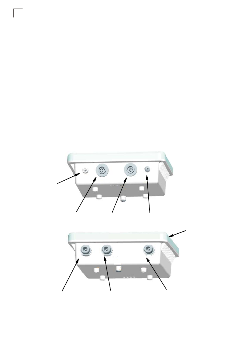
Hardware Description
Bottom View
(both models)
Console Port
CoverAttachment
Top View
(SMC2891W-AG)
N-Type External
Antenna Connector
(2.4 GHz)
1-2
Console Port
Ethernet/PoE
Connector
N-Type External
Antenna Connector
(5 GHz)
Water-Tight Test Point
(DO NOT REMOVE)
Integrated Antenna
N-Type External
Antenna Connector
(2.4 GHz)
Page 22
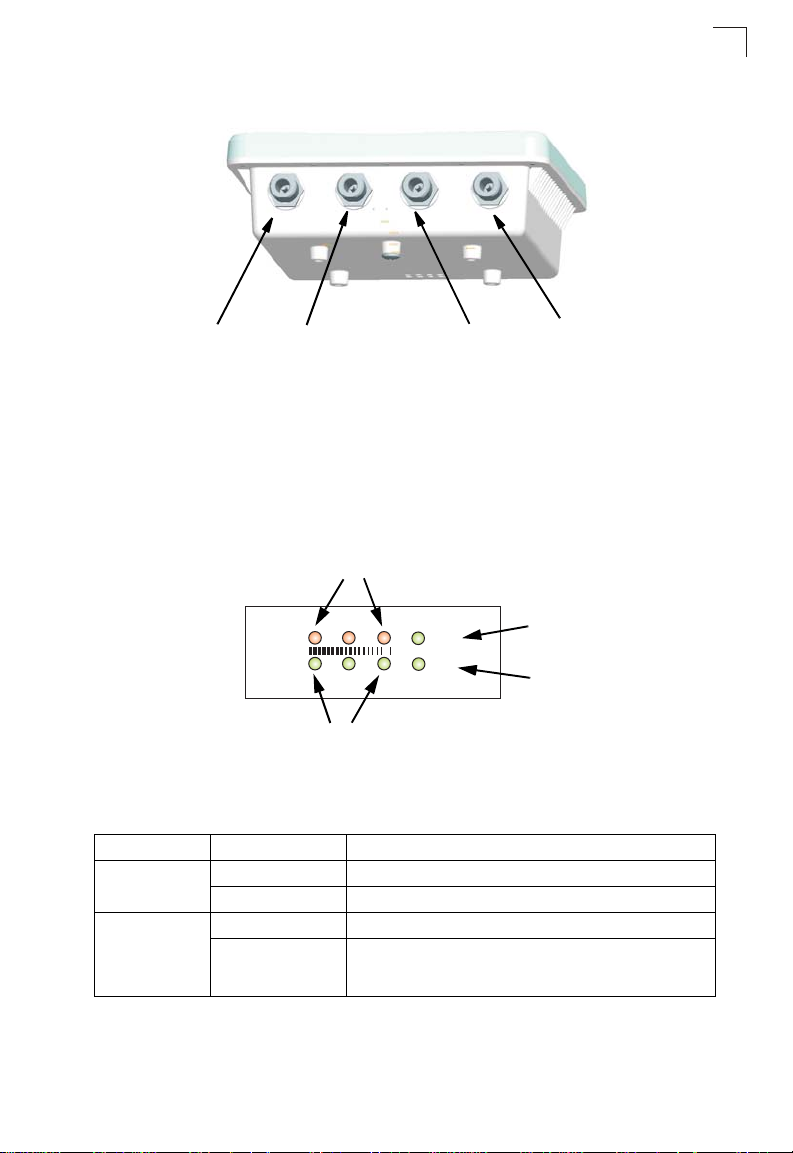
Top View
(SMC2890W-AG)
LED Indicators
1
N-Type External
Antenna Connector
(2.4 GHz)
Right Antenna
N-Type External
Antenna Connector
(5 GHz)
Right Antenna
N-Type External
Antenna Connector
(5 GHz)
Left Antenna
N-Type External
Antenna Connector
(2.4 GHz)
Left Antenna
LED Indicators
The access point includ es eig ht status LED indicators, as indicated in the following
figure.
802.11b/g Wireless
Link/Activity
11b/g
11a
802.11a Wireless
Link/Activity
Power
Link
The following table describe s th e system status LEDs.
LED Status Description
Power On Green Indicates that the system is working normally.
On Amber Indicates a system reset.
Link On Green Indicates a valid 10/100 Mbps Ethernet cable link.
Flashing Green Indicates that the access point is transmitting or receiving data
on a 10/100 Mbps Ethernet LAN. Flashing rate is proportional
to network activity.
Power
Ethernet
Link/Activity
1-3
Page 23

Introduction
1
The 11a and 11b/g LEDs operate in two display mo des, which are configurab le
through the management i nt er face. The RSSI mode is for aligning ant en nas in a
bridge link. The AP mode is for indicating data traffic rates.
The following table describes th e w ire le ss status LEDs in AP mode.
LED Status Description
11a
(three LEDs)
11b/g
(three LEDs)
Off No signal detected or the 802.11a radio is disabled.
Slow Flashing Green The 802.11a radio is enabled with a low level of network
activity.
Fast Flashing Green Indicates a medium level of network activity.
On Green Indicates a high level of network activity.
Off No signal detected or the 802.11b/g radio is disabled.
Slow Flashing Green The 802.11b/g radio is enabled with a low level of network
activity.
Fast Flashing Green Indicates a medium level of network activity.
On Green Indicates a high level of network activity.
The following table describes th e w ire le ss status LEDs in RSSI mode.
LED Status Description
11a
(three LEDs)
11b/g
(three LEDs)
Off No signal detected or the 802.11a radio is disabled.
Slow Flashing Green The 802.11a radio is enabled with a low level signal.
Fast Flashing Green Indicates a medium level signal.
On Green Indicates a high level signal.
Off No signal detected or the 802.11b/g radio is disabled.
Slow Flashing Green The 802.11b/g radio is enabled with a low level signal.
Fast Flashing Green Indicates a medium level signal.
On Green Indicates a high level signal.
1-4
Page 24
Introduction
1
Ethernet Port
The wireless bridge has one 10BASE-T/100 BASE-TX 8-pin DIN port that connects
to the power injector module using the included Etherne t cabl e. The Eth er net port
connection provides pow er to the wireless bridge as we l l as a data lin k t o th e local
network.
The wireless bridge appear s as an Ethernet node and per f orms a bridging function
by moving packets from the wired LAN to the remote end of th e w irel ess bridge link.
Note: The power injector module does not support Power over Ethernet (PoE) based on
the IEEE 802.3af standard. The wireless bridge unit must always be powered on
by being connected to the power injector module.
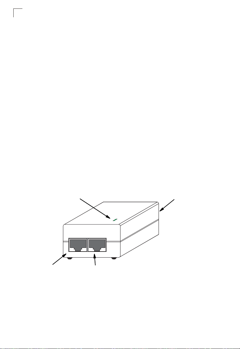
Power Injector Module
The wirele ss bridge rece i ves power through its network cable co nnection us i ng
power-over-Ethernet technology. A power injector module is included in the wireless
bridge package and provides two RJ-45 Ethernet ports, one for connecting to the
wireless bridge (Output ) , and th e ot her for connecting to a local LAN s w itch (Input).
The Input port uses an MDI (i.e., internal straight-through) pin configuration. You can
therefore use straight-through twisted-pair cable to connect this port to most network
interconnection devi ces such as a switch or router tha t pr ov i de M D I -X ports.
However, when connecting the acce ss point to a workstation or other device that
does not have MDI-X po rts, you mu st use crossover twisted -pair ca bl e.
LED Indicator
Input Output
Ethernet from
Local Network
The wireless bridge doe s not ha ve a power switch. It is power ed on when its
Ethernet port is connected to the power injector module, and the power injector
module is connected to an AC pow e r so urce. The power injector inc lu des one LED
indicator that turns on when AC power is applied.
Ethernet and Power
to Wireless Bridge
AC Power Socket
(Hidden)
1-6
Page 25

Grounding Point
The power injector modul e automatically adjusts to an y AC voltage between
100-240 volts at 50 or 60 Hz. No v ol tage range settings are required.
Warning: The power injector module is designed for indoor use only. Never mount
the power injector outside w ith t he wireless bridge unit.
Grounding Point
Even though the wireles s br id ge inc l udes its own built-in lightnin g pr ot ect ion, it is
important that the unit is properl y connected to ground. A grounding screw is
provided for attaching a groun d w i re to the unit.
Water Tight Test Point
Caution: Do no remove or loosen this screw. Doing so could lead t o damage of the
unit.
Wall- and Pole-Mounting Bracket Kit
The wireless bridge includes a bracket kit that can be used to mount the bridge to a
wall, pole, radio mast, or part of a to wer st ru ct ure.
1
1-7
Page 26
Introduction
1
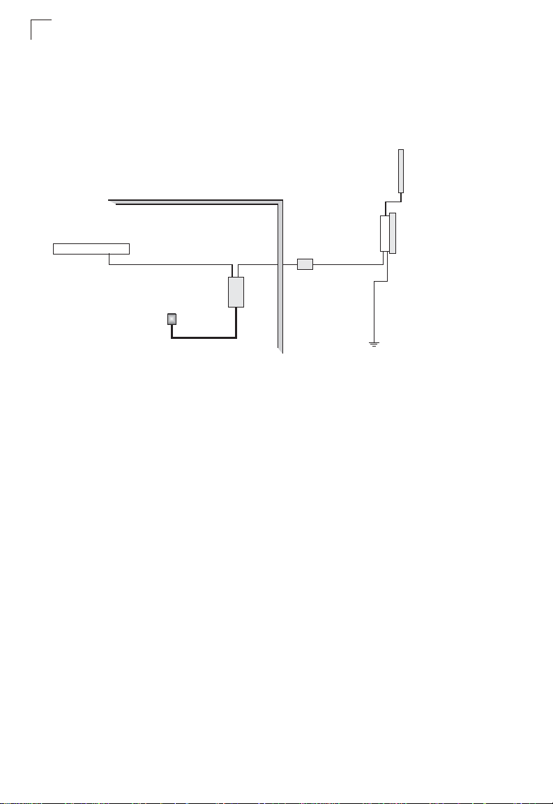
System Configuration
At each location where a un it is in stalled, it must be connected to the l ocal network
using the power injector mo dule. The following figure illustrates the system
component connect i ons .
External Antenna
RF Coaxial Cable
Wireless Bridge Unit
Ground Wire
LAN Switch
Ethernet Cable
AC Power
Indoor Outdoor
Power
Injector
Lightning
Arrestor
Ethernet
Cable
Features and Benefits
• SMC2891W-AG units support a 5 GHz point-to-point wireless link up 15.4 km (at
6 Mbps data rate) using integrated high-gain 17 dBi antennas
• SMC2890W-AG units support 5 G Hz point-to-multipoint lin ks using various
external antenna options
• Both SMC2890W-AG and SMC2891W-AG units also support access po int
services for the 5 GHz and 2.4 GHz radios using various external antenna options
• Maximum data rate up to 108 Mb ps on the 802.11a (5 GHz) radi o
• Outdoor weatherproof design
• IEEE 802.11a and 802.11b/g compliant
• Local network connection via 10/ 100 Mbps Ethernet port
• Powered through its Ethernet cab le connection to the power injec tor m od ul e
• Includes wall- and pole-mount bracket
• Security through 64/128/152- bi t Wir ed Equivalent Protection ( WEP) or 128-bit
Advanced Encryption Standard (AES) encryption
• Scans all available channels and selects the best channel and data rate based on
the signal-to-noise rat io
• Manageable through an easy -t o- us e w eb-browser interface, command line (via
Telnet), or SNMP network management tools
1-8
Page 27

Chapter 2: Network Configuration
The Dual-band Outdoor Acc ess P oint / Bri dge system provides acces s point and
bridging services through either the 5 GHz or 2.4 GH z rad io interfaces.
The wireless bridge units ca n be us ed just as normal 802.11a/b/g access points
connected to a local wired LAN, providing connectivity and roaming services for
wireless clients in an outdoor area. Units can also be used pure l y as b ridges
connecting remote LA N s. Al te rn at iv ely, you can employ both ac cess point and
bridging functions together, offering a flexible and convenient wireless sol ut ion f or
many applications.
This chapter describes the r ol e of Dual - band Outdoor Access Point / Bridge in
various wireless netw or k configurations.
Access Point Topologies
Operating as an outdoo r access point , the unit is deployed in an integrated
configuration with wired Ethernet LANs, provi di ng network access to wire l ess
stations in the wireless coverage area.
The access point’s radios can s upport these modes:
• Infrastructure wireless LAN
• Infrastructure wireless LAN with roaming
• Point-to-point bridge link
• Poin t - to-multipoint brid ge links
The 802.11b and 802.11g frequency band, which operates at 2.4 GHz, can easily
encounter interferen ce f ro m other 2.4 GHz device s, such as other 802.11b or g
wireless devices, cordless phones and microwave ovens. If you experience poor
wireless LAN perform ance, try the following measures:
• Limit any possible sources of radio interference within the service area
• Increase the distance between n ei ghb oring access points
• Increase the channel separation of neighboring access points (e.g., up to 3
channels of separation for 802 .11b or up to 5 channels for 802. 11g)
2-1
Page 28
Network Configuration
2
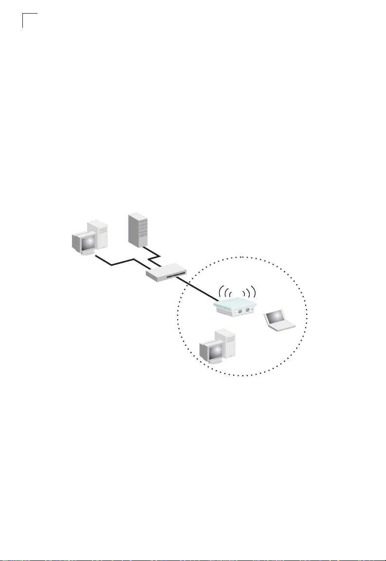
Infrastructure Wireless LAN
The access point function of the wireless bridge provi des access to a wired LAN for
802.11a/b/g wireless workstations. An integrate d w i re d/ wi reless LAN is called an
Infrastructure configurat ion. A Basic Service Set (BSS) consists of a gro up of
wireless PC users and an access point that is directly connected to the wired LAN .
Each wireless PC in a BSS can con nect to any computer in its wireless group or
access other compu te rs or ne tw ork resources in the wired LAN infrastructure
through the access poin t.
The infrastructure configuration not only extends the accessibility of wireless PCs to
the wired LAN, but also increases the effective wireless transmission range for
wireless PCs by passing their si gna ls th ro ugh one or more access po ints.
A wireless infrastructur e c an be used for access to a cent ral database, or for
connection between mo bi l e workers, as shown in the fol lo wi ng f ig ur e.
Wired LAN Extension
to Wireless Clients
Server
2-2
Desktop PC
Switch
Access Point
Notebook PC
Desktop PC
Page 29
Access Point Topologies
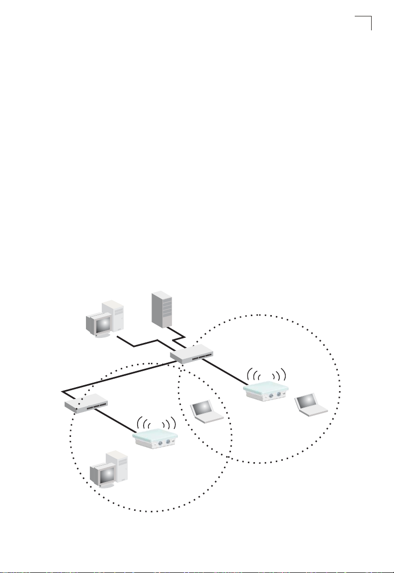
Infrastructure Wireless LAN for Roaming Wireless PCs
The Basic Service Set (BSS) defines the communications domain for each access
point and its associated wirele ss cl ients. The BSS ID is a 48-bit binary num ber
based on the access po int ’s wirel es s M A C ad dress, and is set automat ical l y and
transparently as clients associ ate w i th the access point. The BSS ID is used in
frames sent between the access point and its clients to identify traffic in the service
area.
The BSS ID is only set by the access point, never by its clients. The clie nts only
need to set the Service Set Iden tifi er (SSID ) that ide nti fies the ser vice set provided
by one or more access points. The SSID can be m anually configured by the clien ts,
can be detected in an access point’s beacon, or can be obtained by querying for the
identity of the nearest access point. For clients that do not need to roam, set the
SSID for the wireless card to that used by the access point to whi ch you want to
connect.
A wireless infrastructure can also support roaming for mobile workers. More than
one access point can be conf igured to create an Extended S er vice Set (ESS). By
placing the access poi nts so tha t a c ont i nuous coverage area is cr eat ed, wireless
users within this ESS can ro am freely. All wireless network card adapters and
wireless access points within a specific ESS must be configured with the same
SSID.
Seamless Roaming
Between Access Points
2
Desktop PC
Switch
Access Point
Desktop PC
Server
Notebook PC
<BSS 1>
Switch
Access Point
Notebook PC
<BSS 2>
<ESS>
2-3
Page 30
Network Configuration
2
Bridge Link Topologies
The IEEE 802.11 standard defines a WIreless Distribution System (WDS) for bridge
connections betwee n BSS areas (access points). The outdo or wir eless bridge uses
WDS to forward traffic on links between units. Up to 5 WDS links can be specified for
a SMC2890W-AG unit, which acts as the “Master” in the wireless bridge net w ork.
Other SMC2891W-AG units support only one WDS link, which must be to the
network’s master unit .
The unit supports WDS bridge links on either the 5 GHz (802.11a) or 2.4 GHz
(802.11b/g) bands and can be used with vario us ex t ernal antennas to offer flexible
deployment options.
Note: The external antennas offer longer range options using the 5 GHz radio, which
makes this interface more suitable for bridge links. The 2.4GHz radio has various
types of antenna options, but the 8dBi omnidirectional antenna is better suited for
local access point services.
When using WDS on a radi o band, only wireless bridge units can associate to each
other. Wireless clients can only associate with the wireless bridge using a radio band
set to access point mode.
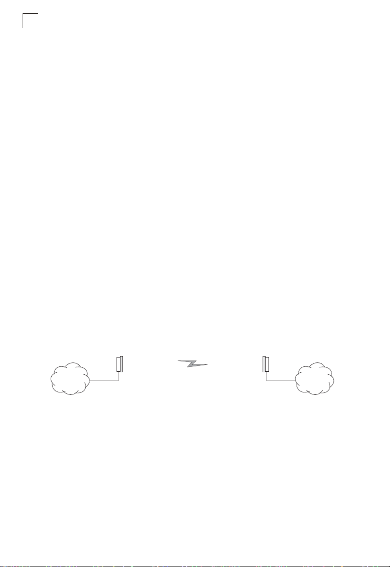
Point-to-Point Configurat ion
Two SM C2891W- AG bridges can form a wireless point-to - point link using their
integrated 5 GHz (802.11a) antennas. A point-to-poi n t co nf ig ur at ion can provide a
limited data rate (6 Mbps) link over a long ra nge (up to 15.4 km), or a high data rate
(108 Mbps) over a short range ( 1. 3 km ) .
2-4
SMC2891W-AG SMC2891W-AG
LANLAN
Page 31

Bridge Link Topologies
Point-to-Multipoint Configuration
A SMC2890W-AG wireless bridge can use an omnidirectional or sector antenna to
connect to as many as 6 b ridges in a point-to-multip oint configuration. There can
only be one “Master” unit i n the w i re le ss bridge network, all other brid ges must be
“Slave” u nits.
Using the 5 GHz 8 dBi omni dire ct i onal external antenna, the SMC2890W-AG can
connect to SMC2891W-AG units up to 3.3 km (2 miles) aw ay. Using the 13.5 dBi
120-degree sector ant enna, the SMC2890W-AG ca n co nnect to SMC2891W-AG
units up to 10.3 km (6.4 miles) away.
2
SMC2891W-AG
SMC2891W-AG
SMC2891W-AG
SMC2890W-AG with
Sector Antenna
SMC2890W-AG with
Omnidirectional
Antenna
SMC2891W-AG
SMC2891W-AG
SMC2891W-AG
SMC2891W-AG
SMC2891W-AG
SMC2891W-AG
2-5
Page 32

Network Configuration
2
2-6
Page 33

Chapter 3: Bridge Link Planning
The Dual-band Outdoor Acc ess P oint / Bri dge supports fixed point-to-poin t or
point-to-multipoint wir eless links. A single link between two points can be used to
connect a remote site to larger core network. Multiple bridge links can provide a way
to connect widespread Ethernet LANs.
For each link in a wireless bridge network to be reliable and provide optimum
performance, some careful site planning is required. This chapter provides guidance
and information for plan ning your wireless bridge l in ks.
Note: The planning and installation of the wireless bridge requires professional
personnel that are trained in the installation of radio transmitting equipment. The
user is responsible for compliance with local regulations concerning items such as
antenna power, use of lightning arrestors, grounding, and radio mast or tower
construction. Therefore, it is recommended to consult a professional contractor
knowledgeable in local radio regulations prior to equipment installation.
Data Rates
Using its 5 GHz integrated ant enn a, th e SM C 2891W-AG bridge can operat e over a
range of up to 15.4 km (9.6 mi le s) or provide a high-speed connection of 54 Mbps
(108 Mbps in turbo mode). However, the maximum data rate for a link decreases as
the operating range incr eases.
When you are planning each wireless bridge link, take into account the maximum
distance and data rates for the var io us antenna options. See “Transmit P ow e r” on
page C-5.
Radio Path Planning
Although the wireless br idge uses IEEE 802.11a radio technology, which is capable
of reducing the effect of multipath si gnals due to obstruction s, the w irel ess bridge
link requires a “radio line-of -s i ght ” bet ween the two antennas for opt imum
performance.
The concept of radio line-of - sight i nvolves the area along a radio l i nk path th ro ugh
which the bulk of the radio sig nal power travels. This area is known as the first
Fresnel Zone of the radio lin k. F or a rad io link not to be affected by obstacles along
its path, no object, including the ground, must intrude within 60% of the first Fresnel
Zone.
The following figure i llustrates the concept of a good radio l i ne-of-sight.
3-1
Page 34

Bridge Link Planning
3
Visual Line of Sight
If there are obstacles in the radi o path , the re may still be a radio link but th e quality
and strength of the signal w i ll be affecte d. C alcul ating the maximum cle ar ance from
objects on a path is important as it directly affects the decision on antenna
placement and height. It is especially critical for long-distance links, where the radio
signal could easily be l ost.
When planning the radio pat h fo r a wir el ess bridge link, consider these factors:
• Avoid any partial line-of-sight be tween the antennas.
• Be cautious of trees or other foliage that may be near the pa th, or m ay g ro w and
obstruct the path.
• Be sure there is enough clearance from buildings and that no building construction
may eventually block the path.
• Check the topology of the land bet w een the antennas using topographical maps,
aerial photos, or even satellite image data (software packages are available that
may include this information for your area)
• Avoid a path that may incur tem porary blockage due to t he m ovement of cars,
trains, or aircraft.
Radio Line of Sight
Antenna Height
A reliable wireless link is us uall y best achieved by mount ing the antennas at each
end high enough for a clear radio line of sight between the m . Th e m i nimum height
required depends on the distance of the link, obstacles that may be in the path,
topology of the terrain, and t he curvature of the earth (fo r lin ks over 3 miles).
For long-distance links, a mast or pole may need to be contsructed to attain the
minimum required hei ght. U se t he following table to estimate the r equired minimum
clearance above the ground or path obstructi on.
3-2
Page 35

Radio Path Planning
.
Total Link Distance Max Clearance for
60% of First Fresnel
Zone at 5.8 GHz
0.25 mile (402 m) 4.5 ft (1.4 m) 0 4.5 ft (1.4 m)
0.5 mile (805 m) 6.4 ft (1.95 m) 0 6.4 ft (1.95 m)
1 mile (1.6 km) 9 ft (2.7 m) 0 9 ft (2.7 m)
2 miles (3.2 km) 12.7 ft (3.9 m) 0 12.7 ft (3.9 m)
3 miles (4.8 km) 15.6 ft (4.8 m) 1.8 ft (0.5 m) 17.4 ft (5.3 m)
4 miles (6.4 km) 18 ft (5.5 m) 3.2 ft (1.0 m) 21.2 ft (6.5 m)
5 miles (8 km) 20 ft (6.1 m) 5 ft (1.5 m) 25 ft (7.6 m)
7 miles (11.3 km) 24 ft (7.3 m) 9.8 ft (3.0 m) 33.8 ft (10.3 m)
9 miles (14.5 km) 27 ft (8.2 m) 16 ft (4.9 m) 43 ft (13.1 m)
12 miles (19.3 km) 31 ft (9.5 m) 29 ft (8.8 m) 60 ft (18.3 m)
15 miles (24.1 km) 35 ft (10.7 m) 45 ft (13.7 m) 80 ft (24.4 m)
17 miles (27.4 km) 37 ft (11.3 m) 58 ft (17.7 m) 95 ft (29 m)
Approximate
Clearance for
Earth Curvature
Total Clearance
Required at
Mid-point of Link
3
Note that to avoid any obs truction along the path, the height of th e object must be
added to the minimum clearance required for a clear radio line-of-sight. Consider the
following simple example, illustrated in the figure below.
Radio Line of Sight
B
1.4 m
9m
12 m
2.4 m
20 m
A
Visual Line of Sight
3miles(4.8km)
5.4 m
17 m
A wireless bridge link is deployed to connect building A to a building B, which is
located three miles (4. 8 km ) aw ay. Mid-way between th e two buidings is a small
tree-covered hill. From the above table it can be seen that for a three-mile link, the
object clearance required at the mid-point is 5.3 m (17.4 ft). The tree-tops on the hill
are at an elevation of 17 m (56 ft), so the antennas at each end of the link need to be
at least 22.3 m (73 ft) high. Building A is six st or ie s high, or 20 m (66 ft), so a 2.3 m
3-3
Page 36

Bridge Link Planning
3
(7.5 ft) mast or pole must be contr uct ed on its roof to achieve the required antenna
height. Building B is only three sto ries hi gh, or 9 m (30 ft), but is lo cated at an
elevation that is 12 m (39 ft) higher than bulding A. To mount an anntena at the
required height on building B, a m ast or pole of only 1.3 m (4.3 ft) is neede d.
Warning:Never construct a radio mast, pole, or tower near overhead power lines.
Note: Local regulations may limit or prevent construction of a high radio mast or tower. If
your wireless bridge link requires a high radio mast or tower, consult a
professional contractor for advice.
Antenna Position and Orientation
Once the required antenna height has been dete rm i ne d, oth er fa ct or s affect in g t he
precise position of the wirel ess bridge must be cons idered:
• Be sure there are no other radio antennas within 2 m (6 ft) of the wir el es s br id ge
• Place the wireless bridge awa y from power and telephone lines
• Avoid placing the wireless bridge too close to any metallic, refective surfaces, such
as roof-installed air-conditioning equipment, tinted windows, wire fences, or water
pipes
• The wireless bridge antennas at both ends of the link must be positioned with the
same polarization direction, either horizon ta l or ve rt ical
Antenna Polarization — The wireless bridge’s integrated antenna sends a radio
signal that is polarized in a particular direction. The antenna’s receive sensitivity is
also higher for radio signals that have the same polarization. To maximize the
performance of the wireless link, both antennas must be set to the same polarization
direction. The unit shoul d be mounted with the antenna sockets facing upwa rd s.
3-4
Antenna sockets should
point upwards in a vertical
manner
Page 37

Ethernet Cabling
3
Radio Interference
The avoidance of radio int er fe re nc e is an i m por tant part of wirel ess link planning.
Interference is caused by other radio transmis si ons using the same or an adjacent
channel frequency. You should first scan your pr oposed site using a spectrum
analyzer to determine if th er e ar e any strong radio signals usi ng the 802.11a
channel frequencies . Alw ay s use a channel frequency that is furthest away from
another signal.
If radio interference is still a pro bl em w it h your wireless bridge link, changing the
antenna pol a ri za tio n dire ct io n may i mpr ove th e si tu at io n. T hi s is on ly rec o mmen de d
when the integrated inte rn al antenna is used.
Weather Conditions
When planning wirele ss bridge links, you must take into acc ount any extreme
weather conditions that ar e known to affect your location. C onsider these factors:
• Temperature — The wireless bridge is tested for normal operati on in tem peratur es
from -40°C to 60°C. Operating in temperatures outside of this range may cause the
unit to fail.
• Wind Velocity — The wireless bridge can operate i n w inds up to 44 m/s and
survive higher wind speeds up to 66 m/s. You must consider the known maximum
wind velocity and direct ion at t he si t e and be sure that any suppor t in g st ru ct ur e,
such as a pole, mast, or tower, is built to withstand this force.
• Lightning — The wireless bridge inc ludes its own built-in lightnin g protection.
However, you should make sure that the unit, any supporting structure, and cables
are all properly grounded. A ddit i onal protection using lightni ng rods, lightning
arrestors, or surge suppressors may also be em ployed.
• Rain — The wireless bridge is weatherproofed against rain. Also, prolonged heavy
rain has no significant ef fe ct on t he r adio signal. However, it is rec om m ended to
apply weatherproof sealing tape around the Ethernet port and antenna connectors
for extra protection. If moisture enters a connector, it may cause a degradation in
performance or even a co mplete failure of the link.
• Snow and Ice — Falling sn ow , like ra in , ha s no significant effect on the rad i o
signal. However, a build up of snow or ice on antennas may cause the link to fail.
In this case, the snow or ice has to be cl ear ed from the antennas to re st or e
operation of the link.
Ethernet Cabling
When a suitable antenna location has been determined, you must plan a cable route
form the wireless bridge outdoors to the power injecto r m odule indoors. Consider
these points:
• The Ethernet cable length should never be longer than 100 m (328 ft)
• Determine a building entry po i nt for th e ca bl e
3-5
Page 38

Bridge Link Planning
3
• Determine if conduits, bracing, or other structures are req ui re d f or saf et y or
protection of the cable
• For lightning protection at the power injector end of the cabl e, consider using a
lightning arrestor imm ediately before the cable en te rs th e buil di ng
Grounding
It is important that the wireless br i dge, cables, and any supp or ting structures are
properly grounded. Th e w ireless bridge unit includes a grounding screw for
attaching a ground wire. Be sur e t hat grounding is availabl e and that it meets local
and national electrical codes.
3-6
Page 39

Chapter 4: Hardware Installation
Before mounting antennas to set up your wireless bridge links, be sure you have
selected appropriate locations for each antenna. Follow the guidance and
information in Chapter 2, “Wi r el es s Li nk Planning.”
Also, before mounting units in their intended locations, you should first perform initial
configuration and test the basic operation of the wireless bridge links in a controlled
environment over a very short range. (See the sect ion “Testing Basic Link
Operation” in this chapter.)
The wireless bridge incl ude s i ts own br acket kit for mounting the unit to a 1.5 to
2 inch di amet er st eel pol e or t ube, or t o a wa ll. The p ole -mo untin g br acke t all ows the
unit to be mounted to part of a radio m ast or to w er struc tu re . The w al l- m ounting
option enables it to be fixed to a building wall or roof when using external antennas.
Hardware installation of the wireless bridge involves these steps:
1. Mount the unit on a wall, pole, mast, or tower using the mounting bracket.
2. Mount external an tennas directly on the bridge or on the same supportin g
structure as the bridge a nd connect them to the bridge unit.
3. Connect the Ether net ca bl e and a grounding wire to the unit.
4. Connect the power inj ector to the Ethernet cable, a local LAN switch, and an
AC power source.
5. Align antennas at both ends of the link.
Testing Basic Link Operation
Set up the units over a very short ra nge (15 to 25 feet), either outdoors or indoors.
Connect the units as indicat ed in this chapter and be sur e to per fo rm all th e basic
configuration tasks outlined in Chapter 5: "Initial Co nfig ur at io n. " W hen you are
satisfied that the links are operating correctly, proceed to mount the units in their
intended locations.
Mount the Unit
The bridge can be mounte d in the fo llowing ways using the inclu ded mounting
bracket:
• To a 1.5 to 2 inch di ameter Pole
• To a w all
4-1
Page 40

Hardware Installation
4
The bridge’s mounting bracket has four parts. One rectangular plate that is used for
pole and wall mounting, one square plate that attaches directly to the bridge, and
two plates that form an adju stab le V-shaped clamp for pol e m ounting.
Mounting on a Pole
Perform the following steps to mount the unit to a 1.5 to 2 inch diameter steel pole or
tube using t he mounting bracket:
1. Fit the edges of the V-shaped clamp parts into the sl ots on the flat si de of the
rectangular plate. The inner slots are for a 1.5 inch diameter pole and the outer
slots for a 2 inch diameter pole.
2. Place the V-shaped clamp parts of the bracket around the pole and tighten the
securing nuts just enough to hol d t he br acket to the pole. (The bra cket may
need to be rotated around the pol e during the antenna alignm ent process.)
Fit the edges of the
V-shaped part into
the slots
Tighten the
securing bolts
3. Attach the square moun tin g pl at e t o the bridge with the supplied scr ew s.
4-2
Page 41

Mount the Unit
Attach the
adjustable
rectangular plate to
the bridge with
supplied screws
4. Attach the bridge with its mounting plate to the bracket already fixed to the pole.
4
Attach th e bridge t o
the plate on the
pole
5. Use the included nu ts to sec u r e th e wi re le ss bridge to the pole bracke t. N ot e
that the wireless bridge tilt angl e m ay need to be adjusted dur i ng the antenna
alignment process.
4-3
Page 42

Hardware Installation
4
Be sure to take account of the antenna polarization direct ion; all antennas in a
link must be mounted with the same polarization.
Mounting to a Wall
Perform the following steps to mo unt the unit to a wall using the wal l-m ounting
bracket:
Note: The wall-mounting bracket does not allow the wireless bridge’s intrgrated antenna
to be aligned. It is intended for use with the unit using external antennas.
1. Attach the bracket to a wall wi th flat si de flush against the wall (se e fol lo wi ng
figure). Position the brack et in the in te nde d l ocation and mark the position of
the four mounting screw holes.
2. Drill four holes in the wall that match the screws and wall plugs included in the
bracket kit, then secure th e bracket to the wall.
3. Attach the square moun tin g pl at e t o the bridge with the supplied scr ew s.
4. Use the included nu ts to tight ly secure the wireless bri dge to the bracket.
4-4
Page 43

Connect External Antennas
Connect External Antennas
When deploying a SMC2891W-AG unit for a bridge link or access point operation,
you need to mount exter nal an te nnas and connect them to the bridge. Typically, a
bridge link requires a 5 GHz antenna, and access poi nt operation a 2.4 GHz
antenna. SMC2890W-AG units also require an extern al ant enna for 2.4 GHz
operation.
4
Perform th ese steps:
1. Mount the externa l an t enn a to th e sam e supporting structur e as the bridge,
within 3 m (10 ft) distance, using the b ra cket supplied in the antenna package.
2. Connect the antenna to t he bridge’s N-type connector using the RF coaxial
cable provided in the ante nn a package. Some omnidirecti onal external
antennas attach directly to an N-t y pe connector without us in g a coaxial cable.
3. Apply weatherproof i ng tap e to the ant enna connectors to hel p pr event water
entering the connectors.
4. Set the antenna option for the corresponding a nt enna through the user
interface. See “Antenna ID” on page 6-59 and “Antenna Con trol M et hod” on
page 6-59.
4-5
Page 44

Hardware Installation
4
2.4 GHz N-type Connector
5 GHz
N-type Connector
RF Coaxial Cable
5 GHz External
High-gain Panel
Antenna
2.4 GHz External
Omnidirectional
Antenna
Connect Cables to the Unit
Warning: Do not connect or disconn ect cables or otherwise work w i th the br idge
during periods of ligh t ning activity.
1. Attach the Ethernet cable to th e Ether net port on the wireless bridge.
2. For extra protection aga in st ra in or moi sture, apply weatherpr oofing tape (not
included) around the Ethe rn et connector.
3. Be sure to ground the unit with an appropriate grounding wire (not included) by
attaching it to the grounding poi nt on the base of the unit using the screw
provided in the package.
Caution: Be sure that grounding is available and that it meets local and national
electrical codes. For addi t io na l lig ht ning protection, use lightn ing r ods,
lightning arrestors, or surge suppressors.
Note: The Ethernet cable included with the package is 30 m (100 ft) long.
4-6
Page 45

Connect the Power Injector
PoE (Ethernet) PortConsole Port
4
Grounding Screw
Ethernet Cable
Ground Wire
Connect the Power Injector
To connect the wireless bridge to a po w er source:
Caution: Do not install the power injector outdoors. The unit is for indoor installation
only.
Caution: Install lightning protection at the power inje ct or end of the Ethernet cable,
use a lightning arrestor im m edi at ely before the cable enters th e bui l ding.
Note: The wireless bridge’s Ethernet port does not support Power over Ethernet (PoE)
based on the IEEE 802.3af standard. Do not try to power the unit by connecting it
directly to a network switch that provides IEEE 802.3af PoE. Always connect the
unit to the included power injector module.
1. Connect the Ether net ca bl e from t he wireless bridge to the RJ -4 5 por t la bel ed
“Output” on the power in je ct or.
2. Connect a straight -thr ough unshielded twisted -pair ( U TP) cab le from a l ocal
LAN switch to the RJ-45 por t labeled “Input” on the power in je ct or. Use
Category 5e or better UTP cable f or 10/ 10 0BASE-TX connections.
Note: The RJ-45 port on the power injector is an MDI port. If connecting directly to a
computer for testing the link, use a crossover cable.
4-7
Page 46

Hardware Installation
4
AC power
Ethernet cable
from LAN switch
Input
Output
Power LED indicator
Ethernet cable to
wireless bridge
1. Insert the power cable plug directly into the standard AC receptacle on the
power injector.
2. Plug the other end of the power cable into a grounded, 3-pin socket, AC power
source.
Note: For International use, you may need to change the AC line cord. You must use a
line cord set that has been approved for the receptacle type in your country.
3. Check the LED on top of the power injector to be sure that power is being
supplied to the wireless br id ge t hr ough the Ethernet connect io n.
Align Antennas
After wireless bridge units have been mounted, connect ed, and their radios are
operating, the antennas must be accurately aligned to ensure optimum performance
on the bridge links. This alignm ent process is particularly imp or tant fo r long-range
point-to-point links. In a poi nt-to-multipoint configuration the root bridge us es an
omnidirectional or sec to r an te nn a, wh i ch do es not require alignment , bu t bri dg e
nodes still need to be correctly aligned with the root bridge antennna.
• Point-to-Point Configurations – In a point-to-poin t co nfi gur at i on, t he ali gnment
process requires two people, one at each end of the link. The use of cell phones or
two-way radio communication may help wit h coordination. To start, you can just
point the antennas at each other, using binoculars or a compass to set the general
direction. For accurate ali gnment, you must monit or the si gnal strength LEDs as
the antenna moves ho rizontally and vertically.
• Point-to-Multipoint Configurations – In a point-to-multipoint configuratio n al l
bridge nodes must be aligned with the root bridge antenna. The alignment process
is the same as in point-to-poi nt links, but only the bridge node end of the link
requires the alignment.
4-8
Page 47

Align Antennas
The signal strength LED s indi cate the received radio sig nal st re ngth for a particular
bridge link. The more LEDs th at turn on, the stronger the signal. Alter natively, you
can monitor the Receive Signal Strength Indicator (RSSI) value directly fro m th e
management interfa ce. The higher the RSSI value , the stronger the signal.
When you move the antenna during alignment, the radio signal from the remote
antenna can be seen to have a strong central main lobe and smaller side lobes. The
object of the alignment process is to set the antenna so that it is receiving the
strongest signal from t he central main lobe.
Vertical Scan
Remote
Antenna
4
Horizontal Scan
RSSI
Value
Main Lobe
Maximum
Maximum Signal Strength Position
for Horizontal Alignment
RSSI Value
Side Lobe
Maximum
Maximum Signal
Strength Position for
Vertical Alignment
To ali gn th e an te nn as in the lin k, mo ni to r t he si gn al st re ngt h L EDs or th e RSS I v al ue
in the management inter fa ce. Start with one antenn a fix ed and then perform the
following procedure on t he o th er ant enna:
Note: The RSSI value can be configured through management interfaces to display a
value for specific WDS bridge links. See page 6-40 for more information.
High 11a Signal
Medium 11a Signal
11b/g
11a
11b/g
11a
Power
Link
Power
Link
Low 11a Signal
11b/g
11a
Power
Link
4-9
Page 48

Hardware Installation
4
1. Pan the antenna hor izontally back and forth while ch ecking the LEDs. If using
the pole-mounting bra cket with the unit, you must ro tate th e mounting bracket
around the pole. Other ext er nal antenna brackets may requi re a different
horizontal adjustment.
2. Find the point where the signal is strongest (all LE D s on ) an d secure the
horizontal adjustment in tha t posi t ion.
Note: Sometimes there may not be a central lobe peak because vertical alignment is too
far off; only two similar peaks for the side lobes are detected. In this case, fix the
antenna so that it is halfway between the two peaks.
3. Loosen the vertica l ad ju st m ent on the mounting brack et and tilt the antenna
slowly up and down while checking the LEDs.
4. Find the point where the signal is strongest and secure the vertical adjust m en t
in that position.
4-10
Page 49

Chapter 5: Initial Configuration
The Dual-band Outdoor Acc ess P oint / Bri dge offers a variety of managemen t
options, including a web-based interface, a dir ect connection to the cons ole port,
Telnet, Secure Shell (SSH), or using SNMP software.
The initial configuration steps can be made through the web browser interface or
CLI. The access point requests an IP address via DHCP by default. If no response is
received from the DHCP server, then the access point uses the default address
192.168.2.2. If this address is not compatible with your network, you can first use the
command line interfac e (C L I) as d escribed below to configure a valid address.
Note: Units sold in countries outside the United States are not configured with a specific
country code. You must use the CLI to set the country code and enable wireless
operation (page 5-3).
Initial Setup through the CLI
Required Connections
The access point provides an RS-232 serial port tha t en ables a connection to a PC
or terminal for monitoring and configuration. Attach a VT100-compatible terminal, or
a PC running a terminal emul at ion program to the access poi nt . You can use the
console cable provide d w i th th is package, or use a cable that com pl i es w it h th e
wiring assignments shown on page B-3.
To connect to the console port, complete the following st eps:
1. Connect the console cable to the serial port on a terminal, or a PC running
terminal emulation software, and tighten the captive retaining screws on the
DB-9 connector.
2. Connect the other end of the cable to the RS-23 2 serial port on the access
point.
3. Make sure the terminal emulation software is set as follows:
• Selec t t he appropri ate serial po r t (COM port 1 or 2).
• Set the data rate to 9600 baud.
• Set the data format to 8 data bits, 1 stop bit, and no parity.
• Set flow control to none.
• Set the emulation mode to VT10 0.
• When using HyperTermin al , s elect Terminal keys, not Windows keys.
4. Once you have set up the terminal correctly, press the [Enter] key to initiate the
console connection. The console login screen will be displayed.
5-1
Page 50

Initial Configura tion
5
For a description of how to use the CLI, see “Using the Command Line Interface” on
page 7-1. For a list of all the CLI commands and detailed informatio n on using the
CLI, refer to “Command Groups” on page 7-6.
Initial Configuration Ste p s
Logging In – Enter “admin” for the user name. The default password is null, so just
press [Enter] at the passwor d pr ompt. The CLI prompt appears displaying the
access point’s name.
Username: admin
Password:
SMC Enterprise AP/Bridge#
Setting the IP Address – By default, the access point is configured to obtain IP
address settings from a DHCP server. If a DHCP server is not available, the IP
address defaults to 192.168 . 2. 2, w hich m ay not be compatible with yo ur net w or k.
You will therefore have to use the command line interface (CLI) to assign an IP
address that is compatible with your network.
Type “configure” to enter configuration mo de, th en type “interface ethern et ” to
access the Ethernet interf ac e- configuration mode.
SMC AP#configure
SMC AP(config)#interface ethernet
SMC AP(config-if)#
First type “no ip dhcp” to disable DHCP client mode. Then type “ip address
ip-address netmask gat ew ay,” where “ip-address” is the access point ’s IP addr ess,
“netmask” is the network mask for the network, and “gateway” is the default gateway
router. Check with your system admin istrat or to obtain an IP address that is
compatible with your network.
SMC AP(if-ethernet)#no ip dhcp
SMC AP(if-ethernet)#ip address 192.168.2.2
255.255.255.0 192.168.2.254
SMC AP(if-ethernet)#
After configuring the access point’s IP parameters, you can access the management
interface from anywhe re wi t hin t he at tac hed network. The comma nd l ine i nt er f ace
can also be accessed usi ng Telnet from any computer attache d to th e net w ork.
5-2
Page 51

Logging In
Setting the Country Code – U ni ts sold in t he U nited States are configured by
default to use only radio cha nnels 1-11 in 802.11b or 802.11g mode as defined by
FCC regulations. Units sold in other countries are configured by default without a
country code (i.e., 99). You must use the CLI to set the country code. Setting the
country code restricts ope ra tion of the access point to th e ra dio channels and
transmit power levels permitted for wireless networks in the specified country .
Type “exit” to leave configuration mode. Then type “country ?” to displ ay the list of
countries. Select the code for your country, and enter the country command again,
following by your countr y code (e.g., tw for Taiwan).
SMC AP#country tw
SMC AP#
Note: Command examples shown later in this manual abbreviate the console prompt to
“AP” for simplicity.
Logging In
There are only a few basic st e ps yo u ne ed t o complete to connect th e access point
to your corporate netwo rk , and pr ovide network access to w irel es s cl i ents.
The access point can be managed by any comput er usi ng a w eb br owser (Internet
Explorer 5.0 or above, or Nets cap e 6. 2 or above). Enter the default IP add ress:
http://192.168.2.2
5
Logging In – Enter the username “admin,” the password is null, so just press just
leave it blank and click LO G IN. For inf or mation on configuring a user name and
password, see page 6-28.
5-3
Page 52

Initial Configura tion
5
The home page displays the Main Menu.
5-4
Page 53

Chapter 6: System Configuration
Before continuing with advanced configuration, first complete the initial configuration
steps described in Chapte r 4 t o set up an IP address for the access point.
The access point can be managed by any comput er usi ng a w eb br owser (Internet
Explorer 5.0 or above, or Netscape 6.2 or above). Enter the configured IP address of
the access point, or use th e def ault address: http://192 .1 68. 2.2
To log into the access point, enter th e de fa ul t us er nam e “admin” and then press
“LOGIN”. When the home page displays, click on Advanced Setup. The following
page will display.
The information in this chap te r is or ganized to reflect the struc tu re of the web
screens for easy refer enc e. H ow e ver, it is recomme nded that you configure a user
name and password as the first st ep under Administration to cont r ol ma nagement
access to this device (page 6- 28) .
6-1
Page 54

System Configuration
6
Advanced Configuration
The Advanced Configur at i on pages include the following o pt io ns.
Table 6-1. Menu
Menu Description Page
System Configures basic administrative and client access 6-3
Identification Specifies the host name 6-3
TCP / IP Settings Configures the IP address, subnet mask, gateway, and domain
RADIUS Configures the RADIUS server for wireless client authentication
SSH Settings Configures Secure Shell management access 6-11
Authentication Configures 802.1X client authentication, with an option for MAC
Filter Control Filters communications between wireless clients, access to the
VLAN Enables VLAN support and sets the management VLAN ID 6-19
WDS Settings Configures bridge or repeater modes for each radio interface and
AP Management Configures access to management interfaces 6-27
Administration Configures user name and password for management
System Log Controls logging of error messages; sets the system clock via
RSSI Configures RSSI value display, bridge link distance, and LED
SNMP Configures SNMP settings 6-40
SNMP Controls access to this access point from management stations
SNMP Trap Filters Defines trap filters for SNMPv3 users 6-48
SNMP Targets Specifies SNMPv3 users that will receive trap messages 6-50
Radio Interface A Configures the IEEE 802 .11a interface 6-51
Radio Settings Configures common radio signal parameters and other settings for
Security Enables each virtual access point (VAP) interface, sets the Service
name servers
and accounting
address authentication
management interface from wireless clients, and traffic matching
specific Ethernet protocol types
sets spanning tree parameters
upgrades software from local file, FTP or TFTP server;
configuration settings to facto ry def ault s; and res ets the acces s
point
SNTP server or manual configuration
display mode
using SNMP, as well as the hosts that will receive trap messages
each VAP interface
Set Identifier (SSID), and configures wireless security
access;
resets
6-4
6-7
6-12
6-17
6-21
6-28
6-33
6-37
6-40
6-53
6-70
6-2
Page 55

Advanced Configuration
Table 6-1. Menu
Menu Description Page
Radio Interface G Configures the IEE E 802 .11g interface 6-5 1
Radio Settings Configures common radio signal parameters and other settings for
Security Enables each VAP interface, sets the SSID, and configures
Status Displays information about the access point and wireless clients 6-88
AP Status Displays configuration settings for the basic system and the
Station Station Shows the wireless clients currently associated with the access
Event Logs Shows log messages stor ed in mem ory 6-93
each VAP interface
wireless security
wireless interface
point
6-68
6-70
6-88
6-91
System Identification
The system name for the ac cess point can be left at its default settin g. Ho wever,
modifyin g thi s p a ra met er can he lp you to mor e ea si ly di st in gui s h di f f er ent devi ce s in
your network.
6
System Name – An alias for the access point, enabling the device to be uniquely
identified on the network. (Def ault : SMC E nter pr ise AP/ Br idge; Range: 1-32
characters)
6-3
Page 56

System Configuration
6
CLI Commands for Sy st em I den ti f ic at io n – Ent er th e gl oba l co nf i gur at i on m ode , an d
use the system name command to specify a new system name. Then return to the
Exec mode, an d use the show system command to display the changes to the
system identification settings.
SMC AP#config 7-8
Enter configuration commands, one per line.
SMC AP(config)#system name R&D 7-14
SMC AP(config)#end 7-90
SMC AP#show system 7-24
System Information
==============================================================
Serial Number :
System Up time : 0 days, 0 hours, 32 minutes, 22 seconds
System Name : Enterprise Wireless AP
System Location :
System Contact : Contact
System Country Code : US - UNITED STATES
MAC Address : 00-12-CF-12-34-60
Radio A MAC Address : 00-12-CF-12-34-61
Radio G MAC Address : 00-12-CF-12-34-65
IP Address : 192.168.2.2
Subnet Mask : 255.255.255.0
Default Gateway : 0.0.0.0
VLAN State : DISABLED
Management VLAN ID(AP): 1
IAPP State : ENABLED
DHCP Client : ENABLED
HTTP Server : ENABLED
HTTP Server Port : 80
HTTP Session Timeout : 300 sec(s)
HTTPS Server : ENABLED
HTTPS Server Port : 443
Slot Status : Dual band(a/g)
Boot Rom Version : v1.1.6
Software Version : v4.3.3.1b05
SSH Server : ENABLED
SSH Server Port : 22
Telnet Server : ENABLED
DHCP Relay : DISABLED
==============================================================
SMC AP#
6-4
Page 57

Advanced Configuration
TCP / IP Settings
Configuring the access point with an IP address expands your ability to manage the
access point. A number of access point features depe nd on IP addressing to
operate.
Note: You can use the web browser interface to access IP addressing only if the access
point already has an IP address that is reachable through your network.
By default, the access point will be automatically configured with IP settings from a
Dynamic Host Configuration Protocol (DHCP) server. However, if you are not using
a DHCP server to configure IP addressing, use the CLI to manually configure the
initial IP values (see page 5-2). After y ou have network access t o th e ac cess point,
you can use the web brow ser in te rface to modify the initial IP configuration, if
needed.
Note: If there is no DHCP server on your network, or DHCP fails, the access point will
automatically start up with a default IP address of 192.168.2.2.
6
DHCP Client (Enable) – Select this option to obtain the IP settings for the access
point from a DHCP (Dynamic Host Configuration Protocol) server. The IP address,
subnet mask, default ga te way, and Domain Name Server (DNS) address are
dynamically assigned to the access point by the network DHCP server.
(Default: Enabled)
DHCP Client (Disable) – Select this option to manually configure a static address for
the access point.
• IP Address: The IP address of the access point. Valid IP addresses consist of four
decimal numbers, 0 to 255, separated by periods.
• Subnet Mask: The mask tha t identifies the host address bi ts used for routing to
specific subnets.
6-5
Page 58

System Configuration
6
• Default Gateway: The default gateway is the IP address of the router for the access
point, which is used if the requested destination address is not on the local subnet.
If you have management st at ions, DNS, RADIUS, or other network servers
located on another subnet, type the IP address of the default gateway router in the
text field provided. Otherwise, leave the address as all zeros (0.0.0.0).
• Primary and Secondary DNS Addre ss: The IP address of Domain Na m e Se rv ers
on the network. A DNS maps numerical IP addresses to domain names and can
be used to identify network hosts by familiar names instead of the IP addresses.
If you have one or more DNS servers located on the local network, type the IP
addresses in the text fields provided. Otherwise, leave the addresses as all zeros
(0.0.0.0).
CLI Commands for TCP/IP Settings – From the global configuration mode, enter the
interface configuration mode with the interface ethernet command. Use the ip
dhcp command to enable the DHCP client, or no ip dhcp to disable it. To manually
configure an address, specify the new IP addres s, subnet mask, and default
gateway using the ip address command. To specify DNS server addresses use the
dns server command. Then use the show interf ace ethernet command fr om t he
Exec mode to display the current IP settings.
SMC AP(config)#interface ethernet 7-90
Enter Ethernet configuration commands, one per line.
SMC AP(if-ethernet)#no ip dhcp 7-92
SMC AP(if-ethernet)#ip address 192.168.1.2
255.255.255.0 192.168.1.253 7-91
SMC AP(if-ethernet)#dns primary-server 192.168.1.55 7-91
SMC AP(if-ethernet)#dns secondary-server 10.1.0.55 7-91
SMC AP(config)#end 7-8
SMC AP#show interface ethernet 7-94
Ethernet Interface Information
========================================
IP Address : 192.168.1.2
Subnet Mask : 255.255.255.0
Default Gateway : 192.168.1.253
Primary DNS : 192.168.1.55
Secondary DNS : 10.1.0.55
Admin status : Up
Operational status : Up
========================================
SMC AP#
6-6
Page 59

Advanced Configuration
RADIUS
Remote Authentication D ial - in User Ser vi ce (RAD I US) is an authentication prot oc ol
that uses software running on a central server to cont r ol acc ess to RADIUS-aware
devices on the network. An authentication server co ntains a database of user
credentials for each user that requires access to the network.
A primary RADIUS server must be specified for the access point to implement IEEE
802.1X network access control and Wi-Fi Protected Access (WPA) wireless security.
A secondary RADIUS ser ve r m ay als o be specified as a backup s hou ld th e pr imary
server fail or become inaccessible.
In addition, the configured R A DI U S server can also act as a RAD I US Acc ounting
server and receive user -s ession accounting info rm ation from the access po in t .
RADIUS Accounting c an be used to provide valuable i nf or m at io n on user activity in
the network.
Note: This guide assumes that you have already configured RADIUS server(s) to
support the access point. Configuration of RADIUS server software is beyond the
scope of this guide, refer to the document ation provided with the RADIUS server
software.
6
6-7
Page 60

System Configuration
6
6-8
Page 61

Advanced Configuration
MAC Address Format – MAC addresses can be specified in one of four formats,
using no delimeter, with a single dash delim et er, with multiple das h delimeters, and
with multiple colon delimeters.
VLAN ID Format – A VLAN ID (a number bet ween 1 and 4094) can be assi gn ed to
each client after successful authentication using IEEE 802.1X and a central RADIUS
server. The user VLAN IDs must be configured on the RADIUS server for each user
authorized to access the network. VLAN IDs can be ent er ed as hexadecimal
numbers or as ASCII strin gs.
Primary Radius Server Setup – Configure the following settings to use RADIUS
authentication on the ac cess point.
• Radius Status: Enabling Radius Status allows the settings of RADIUS
authentication. (Defau lt: E nab l e)
• IP Address: Specifies the IP address or host name of the RAD I U S server.
• Port: The UDP port number used by the RADIUS server for authentication
messages. (Range: 1024-65535; Default: 181 2)
• Key: A shared text string used to encrypt messages between the access point and
the RADIUS server. Be sure that the same text string is specified on the RADIUS
server. Do not use blank s paces in the string. (Maxim um l ength: 255 characters)
• Timeout: Number of second s th e access point waits for a re ply f rom the RADIUS
server before resending a request. (Range: 1-60 seconds; Default: 5)
• Retransmit attempts: The number of times the access point tries to resend a
request to the RADIUS server before authentication fails. (Range: 1-30; Default: 3)
• Accounting Port: The RADIUS Accounting server UDP port used for accounting
messages. (Range: 0 or 1024-65535; Default: 0, disabl ed)
• Interim Update T i m eout: The in terval bet w een transmi tting accounting updates to
the RADIUS server. (Range: 60-86400; Default: 3600 seconds)
Note: For the Timeout and Retransmit attempts fields, accept the default values unless
you experience problems connecting to the RADIUS server over the network.
6
Secondary Radius Server Setup – Configure a secondary RADIUS server to provide
a backup in case the prim ar y server fails. The access poi nt uses the secondary
server if the primary server fails or becomes inaccessible. Once the access point
switches over to the sec ondary server, it periodically attempts to establish
communication aga in w i th prim ar y server. If communication with the prim ar y server
is re-established, the secondary server reverts to a ba ckup role.
6-9
Page 62

System Configuration
6
CLI Commands for RADIUS – From the global configuration m ode, use the
radius-server address com m and to specify the address of the primary or
secondary RADIUS servers. (The following example configures the settings for the
primary RADIUS server.) Configure the other parameters for the RADIUS server.
Then use the show show radius command from the Exec mode to display the
current settings for the p rimary and secondary RADIUS servers.
SMC AP(config)#radius-server address 192.168.1.25 7-60
SMC AP(config)#radius-server port 181 7-61
SMC AP(config)#radius-server key green 7-61
SMC AP(config)#radius-server timeout 10 7-62
SMC AP(config)#radius-server retransmit 5 7-62
Enterprise AP(config)#radius-server port-accounting 1813 7-63
Enterprise AP(config)#radius-server timeout-interim 500 7-63
SMC AP(config)#exit
SMC AP#show radius 7-65
Radius Server Information
========================================
IP : 192.168.1.25
Port : 181
Key : *****
Retransmit : 5
Timeout : 10
Radius MAC format : no-delimiter
Radius VLAN format : HEX
========================================
Radius Secondary Server Information
========================================
IP : 0.0.0.0
Port : 1812
Key : *****
Retransmit : 3
Timeout : 5
Radius MAC format : no-delimiter
Radius VLAN format : HEX
========================================
SMC AP#
6-10
Page 63

Advanced Configuration
SSH Settings
Telnet is a remote management to ol tha t c an be used to configure the access point
from anywhere in the ne twork. However, Telnet is not secure from hostile at tack s.
The Secure Shell (SSH) can act as a se cur e r epl acement for Telnet. The SSH
protocol uses generated public keys to encryp t all data transfers passing between
the access point and SSH -e nabled management station cl ients an d ensures that
data traveling over the netw or k ar rives unaltered. Clients can th en securely use the
local user name and password for access authentication.
Note that SSH client software nee ds to be installed on the management station to
access the access poi nt for m anagement via the SSH pro to co l.
Notes: 1. The access point supports only SSH version 2.0.
2. After boot up, the SSH server needs about two minutes to generate host
encryption keys. The SSH server is disabled while the keys are being
generated.
6
SSH Settings
Telnet Server Status – Enables or disables the Telnet server. (Default: Enabled)
SSH Server Status – Enables or disables the SSH se rv er. (Default: Enabl ed)
SSH Server Port – Sets the UDP port for the SSH ser ve r. (Range: 1-65535;
Default: 22)
6-11
Page 64

System Configuration
6
CLI Commands for SSH – To enable the SSH server, use the ip ssh-server enable
command from the CLI Et her ne t inter f ace configuration mode. To set the SSH
server UDP port, use the ip ssh-server port command. To view the current settings,
use the show system command from the CLI Exec mode (not shown in the
following example).
Enterprise AP(if-ethernet)#no ip telnet-server 7-17
Enterprise AP(if-ethernet)#ip ssh-server enable 7-16
Enterprise AP(if-ethernet)#ip ssh-server port 1124 7-16
Enterprise AP(if-ethernet)#exit
Enterprise AP(if-ethernet)#configure
Authentication
Wireless clients can be auth ent i cat e d for network access by chec ki ng the i r M AC
address against the local database configured on the ac cess point, or by using a
database configured on a ce nt ra l RADIUS server. Alternatively, authentication can
be implemented using the IEEE 802.1X network access control protocol.
A client’s MAC address provides relatively weak user authentication, since MAC
addresses can be easily captured and used by an ot her station to break into the
network. Using 802.1X pr ov id es more robust user authe nt ic at ion using user names
and passwords or digital certificates. You can configure the access point to use both
MAC address and 802.1X authentication, with client station MAC authentication
occurring prior to IEEE 802.1X authentication. However, it is better to choose one or
the other, as appropriate.
Take note of the following points before configuring MAC addr es s or 802.1X
authentication:
• Use MAC address authen tic at io n fo r a s m al l ne t work with a limited number of
users. MAC addresses can be manually conf i gured on the access point itself
without the need to set up a RADIUS server, but managing a large number of MAC
addresses across many access points is very cumbersome. A RADIUS server can
be used to centrally manage a larger database of user MAC addresses.
• Use IEEE 802.1X authenticat i on for networks with a larger number of users and
where security is the mos t important issue. When using 802.1X authenticati on, a
RADIUS server is required in the wired network to centrally manage the credentials
of the wir eless clients . It al so prov ides a mec hanis m for enha nced ne twork s ecurity
using dynamic encryp tion key rotation or W-Fi Protect ed Ac cess (WPA).
Note: If you configure RADIUS MAC authentication together with 802.1X, RADIUS MAC
address authentication is performed prior to 802.1X authentication. If RADIUS
MAC authentication succeeds, then 802.1X authentication is performed. If
RADIUS MAC authentication fails, 802.1X authentication is not performed.
• The access point can also operate in a 802.1X supplicant mode. This enables the
access point itself to be authenticated with a RADI U S server using a configured
MD5 user name and password. This prevents rog ue access points from gai ning
access to the network.
6-12
Page 65

Advanced Configuration
MAC Authentication – You can configure a list of the MAC ad dresses for wireless
clients that are authorized to access the network. This pro vi des a basic level of
authentication for wireless cli ents attempting to gai n access to the net work. A
database of authorized MAC addresses can be stored locally on the access point or
remotely on a central RADIUS server.
(Default: Disabled)
• Disabled: No checks are perf or m ed on an associating stat io n’ s M AC address.
• Local MAC: The MAC addres s of th e as sociating station is compared against the
local database stored on t he access point. Use the Lo cal MAC Authenticatio n
section of this web page to se t up th e l oca l d at abase, and configure all acc ess
points in the wireless network service area with the same MAC address database.
• Radius MAC: The MAC add re ss of t he associating station is s ent to a configured
RADIUS server for authentication. When using a RADIUS authentication server for
MAC address authent ic at ion, t he server must first be conf igured in the Radius
window (see “RADIUS” on page 6-7). The database of MAC addresses and
filtering policy must be de f ined i n t he R ADIUS server.
Note: MAC addresses on the RADIUS server can be entered in four different formats
(see “RADIUS” on page 6-7).
6
802.1X Supplicant – The access point can also operat e in a 802.1X supplicant
mode. This ena bles the acce ss p oint it se lf t o be au then ti cate d wi th a RA DIU S serv er
using a configured MD5 use r name and password. This prevents rogue access
points from gaining access t o th e ne twork.
6-13
Page 66

System Configuration
6
Local MAC Authentication – Configures the local MAC authentication database. The
MAC database provides a me chanism to take certain actions based on a wireless
client’s MAC address. The MA C lis t ca n be configured to allow or deny network
access to specific clients.
• System Default: Specifies a default action for all unknown MAC addresses (that is,
those not listed in the local M AC database).
• Deny: Blocks access for all MAC addresses except thos e listed in the local
database as “Allow.”
• Allow: Permits access for all MAC addresses excep t those listed in the local
database as “Deny.”
• MAC Authentication Settings: Ent er s sp ecified MAC addresse s and permissions
into the local MA C databa s e.
• MAC Address: Physical address of a client. Enter six pairs of hexadecimal digits
separated by hyphens; for example, 00-90-D1-12-AB-89.
• Permission: Select Allow to permit access or Deny to block access. If Delete is
selected, the specified MAC address entry is r em oved from the database.
• Update: Enters the specified MAC address and permission setting into the local
database.
• MAC Authentication Table: Displays current entries in the local MAC database.
6-14
Page 67

Advanced Configuration
CLI Commands for Local MAC Authentication – Use th e mac-authentication
server command from the global config ur at ion mode to enable local MAC
authentication. Use the m ac-authentication session-timeout command to set the
authentication interval , an d w eb-redirect command t o enable web-based
authentication for service billing. Set the default action for MAC addresses not in the
local table using the address filter default command, then enter MAC addresses in
the local table usin g t he address filter entry command. To remove an entry from
the table, use the address filt er del et e command. To display the current settings,
use the show authentica tion command from the Exec mode.
SMC AP(config)#mac-authentication server local 7-73
SMC AP(config)#mac-authentication session-timeout 5 7-73
SMC AP(config)#web-redirect 7-20
SMC AP(config)#address filter default denied 7-71
SMC AP(config)#address filter entry
00-70-50-cc-99-1a denied 7-72
SMC AP(config)#address filter entry
00-70-50-cc-99-1b allowed
SMC AP(config)#address filter entry
00-70-50-cc-99-1c allowed
SMC AP(config)#address filter delete
00-70-50-cc-99-1c 7-72
SMC AP(config)#exit
SMC AP#show authentication 7-69
Authentication Information
===========================================================
MAC Authentication Server : LOCAL
MAC Auth Session Timeout Value : 0 min
802.1x supplicant : DISABLED
802.1x supplicant user : EMPTY
802.1x supplicant password : EMPTY
Address Filtering : DENIED
System Default : ALLOW addresses not found in filter table.
Filter Table
MAC Address Status
----------------- ---------00-70-50-cc-99-1a DENIED
00-70-50-cc-99-1b ALLOWED
=========================================================
SMC AP#
6
6-15
Page 68

System Configuration
6
CLI Commands for RADIUS MAC Authentication – Use the mac-authentication
server command from the global config ur at ion mode to enable remote M A C
authentication. Set the tim eou t val ue f or re-authentication using the macauthenti cation sessi on-timeout command. Be sure to als o configure connection
settings for the RADIUS server (not shown in the fo llowing example). To display the
current settings, us e t he show authentication com m and from the Exec mode.
SMC AP(config)#mac-authentication server remote 7-73
SMC AP(config)#mac-authentication
session-timeout 300 7-73
SMC AP(config)#exit
SMC AP#show authentication 7-69
Authentication Information
===========================================================
MAC Authentication Server : REMOTE
MAC Auth Session Timeout Value : 300 min
802.1x supplicant : DISABLED
802.1x supplicant user : EMPTY
802.1x supplicant password : EMPTY
Address Filtering : DENIED
System Default : DENY addresses not found in filter table.
Filter Table
MAC Address Status
----------------- ---------00-70-50-cc-99-1a DENIED
00-70-50-cc-99-1b ALLOWED
=========================================================
SMC AP#
CLI Command for 802.1x Sup pl ic an t – To configure the access point to operate as a
802.1X supplicant, first us e t he 802.1X supplicant user command to set a user
name and password for the access point, then use the 802.1X supplicant command
to enable the feature. To display the current settings, use the show authentication
command from the Exec m ode (not shown in the follow ing example)
SMC AP(config)#802.1X supplicant user secureAP dot1xpass 7-69
SMC AP(config)#802.1X supplicant 7-69
SMC AP(config)#
6-16
Page 69

Advanced Configuration
Filter Control
The access point can empl oy network traffic frame filterin g to control access to
network resources and increase security. You can prevent communications between
wireless clients and prevent access point mana gement from wireless clie nt s. Al so,
you can block specific Eth er net tr af f ic fr om being forwarded by the a ccess point.
6
Inter Client STAs Communication Filter – Sets the global mode for
wireless- to- wir eles s co mmunic at ions betwe en c lie nt s asso ciat ed t o V irt ual A P (VAP )
interfaces on the access point. (Default: Prevent Inter and Intra VAP client
Communication)
• Disabled: All clients can communicate with each other thr ough the access point.
• Prevent Intra VAP client communication: When enabled, clients associated with a
specific VAP interface cannot establish wireless communications with each other.
Clients can communicate with clients associated to other VAP interfaces.
• Prevent Inter and Intra VAP client com m unication: When enabled, clients cannot
establish wireless communications with any other client, either those associated to
the same VAP interface or any other VAP interface.
AP Management Filter – Controls manageme nt access to the access poin t fro m
wireless clients. Management interfaces include the web, Telnet, or SNMP.
(Default: Disabled)
• Disabled: Allows management access from wireless clients.
• Enabled: Blocks management access from wireless clients.
6-17
Page 70

System Configuration
6
Uplink Port MAC Address Filterin g Status – Prevents traffic with specified source
MAC addresses from bei ng forwarded to wireless clients through the access po int.
You can add a maximum of four MAC addresses to the filter table. (Default:
Disabled)
• MAC Address: Specvifies a MAC address to filter, in the form xx-xx-xx-xx-xx-xx.
• Permission: Adds or deletes a MAC address from the filtering table.
Ethernet Type Filter – Controls checks on the Eth er net ty pe of all incoming and
outgoing Ethernet packets again st the protocol filtering table. (Defau lt: Dis abled)
• Disabled: Access point does n ot filter Et her net protocol types.
• Enabled: Access point filters Ethernet protocol types based on the configuration of
protocol t ypes in the filter tabl e. If the st atus of a prot ocol is set to “ON,” the pr otocol
is filtered from the access point.
Note: Ethernet protocol types not listed in the filtering table are always forwarded by the
access point.
Ethernet Type Filter – Enables or disables Ethernet filtering on the port. (Default:
Disabled)
CLI Commands for Bridge Filtering – Use the filter local-bridge command from the
global configuration m ode to prevent wireless-to-wireless communi cations through
the access point. Use the fil te r ap-manage command to restrict management
access from wireless cl i ents. To configure Ethernet protocol filte ring, use the filter
ethernet-type enable command to enable filter in g and the filter ethernet-type
protocol command to define the protocols that you want to filter. T o remove an entry
from the table, use the address filter delete command. To display the current
settings, use the show filters command from the Exec mode.
SMC AP(config)#filter local-bridge 7-75
SMC AP(config)#filter ap-manage 7-75
SMC AP(config)#filter uplink enable 7-76
SMC AP(config)#filter uplink add 00-12-34-56-78-9a 7-76
SMC AP(config)#filter ethernet-type enable 7-76
SMC AP(config)#filter ethernet-type protocol ARP 7-77
SMC AP(config)#exit
SMC AP#show filters 7-78
Protocol Filter Information
=========================================================
Local Bridge :ENABLED
AP Management :ENABLED
Ethernet Type Filter :ENABLED
Enabled Protocol Filters
--------------------------------------------------------Protocol: ARP ISO: 0x0806
=========================================================
SMC AP#
6-18
Page 71

Advanced Configuration
VLAN
The access point can employ VLAN tagging support to control access to network
resources and increase security. VLANs separate traffic passing between the
access point, associat ed cl ients, and the wired network. T her e c an be a VLAN
assigned to each associ at ed client, a default VLAN for each VAP (Virtual Access
Point) interface, and a management VLAN for the access point.
Note the following points about the access point’s VLAN support:
• The management VLAN is for managing the access point through remote
management tools, such as the web interface, SSH, SNMP, or Telnet. The access
point only accepts management traffic that is tagg ed with the specified
management VLAN ID.
• All wireless clients associated to the access point are assigned to a VLAN. If IEEE
802.1X is being used to authenticate wireless client s, specific VLAN IDs can be
configured on the RADI US server to be assigned to each client. If a client is not
assigned to a specific VLAN or if 802.1X is not used, the clien t is as signed to the
default VLAN for the VAP interfa ce wi t h whi ch it is associated. The access point
only allows traffic tagged w it h assigned VLAN IDs or defaul t VLAN I Ds t o access
clients associated on ea ch VAP interface.
• When VLAN support is enable d on t he access point, traffic pa ss ed t o t he w i r ed
network is tagged with the appropriate VLAN ID, either an assigned client VLAN
ID, default VLAN ID, or the management VLAN ID. Traffic received from the wired
network must also be tagged with one of these known VLAN IDs. Received traffic
that has an unknown VLAN ID or no VLAN t ag is dropped.
• When VLAN support is disabled, the access point does not tag traffic passed to the
wired network and ignores t he VLAN tags on any received f ra m es.
Note: Before enabling VLAN tagging on the access point, be sure to configure the
attached network switch port to support tagged VLAN frames from the access
point’s management VLAN ID, default VLAN IDs, and other client VLAN IDs.
Otherwise, connectivity to the access point will be lost when you enable the VLAN
feature.
6
Using IEEE 802.1X and a cen t ral RA DI U S server, up to 64 VLAN IDs can be
mapped to specific wirel ess clients, allowing users to rem ai n wi th in the sam e VLAN
as they move around a campus site. This feature can also be used to control access
to network resources f rom clients, thereby improvin g security.
A VLAN ID (1-4094) can be ass i gned to a client after successful IEE E 802.1X
authentication. The client VLAN IDs must be configured on the RADIUS server f or
each user authorized to access the network. If a clie nt does not have a configured
VLAN ID on the RADIUS server, the access point assigns the client to the
configured default VLAN I D fo r the VAP interface.
Note: When using IEEE 802.1X to dynamically assign VLAN IDs, the access point must
have 802.1X authentication enabled and a RADIUS server configured. Wireless
clients must also support 802.1X client software.
6-19
Page 72

System Configuration
6
When setting up VLAN IDs for each user on the RADIUS server, be sure to use the
RADIUS attributes an d values as indicated in the f ollo w i ng tab le.
Number RADIUS Attribute Value
64 Tunnel-Type VLAN (13)
65 Tunnel-Medium-Type 802
81 Tunnel-Private-Group-ID VLANID
VLAN IDs on the RADIUS ser ver can be entered as hexade ci m al di gi t s or a string
(see “radius-server vlan-format” on page 7-64 ).
Note: The specific configuration of RADIUS server software is beyond the scope of this
guide. Refer to the documentation provided with the RADIUS server software.
(1 to 4094 as hexadecimal or string)
VLAN Classification – Enables or disables VLAN tagg in g su pport on the access
point.
Native VLAN ID – The VLAN ID that traffic must have to be able to manage the
access point. (Range 1- 4094; Default: 1)
6-20
Page 73

Advanced Configuration
WDS Settings
Each access point radio inte rface can be configured to o per at e i n a br idge or
repeater mode, which al low s i t to fo rward traffic directly to other access point units.
To set up bridge links between access point units, you must configure the wireless
Distribution System (WDS) forwarding table by specifying the wireless MAC address
of all units to which you want to forw ar d tr affic. Up t o si x W D S br i dge or r epeater
links can be specified fo r ea ch unit in the wireless bridge network.
The Spanning Tree Protocol (STP) can be used to detect and disable network loops,
and to provide backup links between bridges. This allows a wireless bridge to
interact with other bridgi ng devices (that is, an STP- com p l ia nt swi tc h, bridge or
router) in your network to ensure that only one route exists between any two stations
on the network, and provi de b ac kup links which automat ic ally take o ver w hen a
primary link goes down.
6
WDS Bridge – Up to six WDS bridg e or rep eater links (MAC addresses) per radio
interface can be specified for each unit in the wireless bridge network. One unit only
must be configured as the “root br id ge” in the wireless network. The root bridge is
the unit connected to the main core of the wired LAN. Other bridges need to specify
one “Parent” link to the root br id ge or to a bridge connected to th e ro ot bridg e. The
other five WDS links are avai labl e as “Child” links to other bridg es.
• Bridge Role – Each radio interface can be set to operate in one of the following four
modes: (Default: AP)
• AP (Access Point): Operates as an access point for wireless clients, providing
connectivity to a wired LAN.
6-21
Page 74

System Configuration
6
• Bridge: Operates as a bridge to other access points. The “Parent” link to the root
bridge must be configur ed. Up to five other ”Child” links are available to other
bridges.
• Repeater: Operates as a wirel ess repeater, extendin g th e ra nge for remote
wireless clients and connecting them to the root bridge. The “Parent” link to the
root bridge must be conf ig ur ed. In th is mo de, traffic is not forwarded to the
Ethernet port from the radio inter f ace.
• Root Bridge: Operates as the root bridge in the wireless bridge network. Up to
six ”Child” links are avai labl e to ot her br id ges in the network.
• Master/Slave Mode – Selects between Master and Slave mode. A single m as te r
enables up to five slave links, whereas a slave will have only one link to the master.
• Bridge Parent – The physical layer address of the root bridge unit or the bridge unit
connected to the root bridge. (12 hexadecimal digits in the form
“xx-xx-xx-xx-xx-xx”)
• Channel Auto Sync – Allows a Bridge Child to automatically find the operating
channel used by its Bridge Pa re nt.
Caution:Do not enable Channel Auto Sync on a master bridge if there is no root bridge
acting as the master bridge's parent.
• Bridge Child – The phys ical la yer address of other bridge unit s f or wh i ch thi s unit
serves as the bridge parent or the root bridge. Note that the first entry under the list
of child nodes is reserved for the root bridge, and can only be configured if the role
is set to “Root Bridge.” (12 hexadeci m al d ig i ts in t he form “xx-xx-xx -xx-xx-xx”)
6-22
Page 75

Advanced Configuration
6
Spanning Tree Protocol – STP uses a distributed algorithm to selec t a bri dg in g
device (STP-compliant sw i t ch , br idge or router) that serves as t he root of the
spanning tree network. It se l ects a roo t po rt on each bridging device (ex cept for the
root device) which incurs the lowest path cost when forwarding a packet from that
device to the root device. Then it selects a designated brid gi ng device from each
LAN which incurs the lowest path cost when forwarding a packet from that LAN to
the root device. All ports connec te d to designated bridging devices are assigned as
designated ports. After determining the lowest cost spanning tree, it enables all root
ports and designated ports, an d di sables all other ports. Network packets are
therefor e only forwar ded between ro ot ports and designated ports, eliminating any
possible network loops.
6-23
Page 76

System Configuration
6
Once a stable network topol ogy has been established, all br id ges listen for Hello
BPDUs (Bridge Protocol Data Units) transmitted from the root bridge. If a bridge
does not get a Hello BPDU after a pre def i ne d in t erv al (M aximum Age), the bridge
assumes that the link to th e ro ot bridge is down. This bridge w ill the n i ni tia te
negotiations with othe r bri dges to reconfigure the ne twork to reestablish a valid
network to pology.
• Bridge – Enables/disables STP on the wireless bridge or repeater.
(Default: Disabled)
• Bridge Priority – Used in selecting the root device, root port, and designated port.
The device with the highest pr io rit y be com es the STP root device. How ev er , if all
devices have the same priority, the device with the lowest MAC address will then
become the root devic e. (Not e tha t low er numeric values indic at e hi gher priority.)
• Range: 0-65535
• Default: 32768
• Bridge Max Age – The maximum tim e (in seconds) a device can w ai t without
receiving a configurati on m essage before attempt i ng t o re configure. All device
ports (except for design at ed ports) should receive configuration messag es at
regular intervals. Any port tha t ages out STP i nf or m ati on ( pr ovi d ed i n th e last
configuration message) becomes the designated port for the attached LAN. If it is
a root port, a new root port is selected from among the device ports attached to the
network. (Range: 6-40 seconds)
• Default: 20
• Minimum: The higher of 6 or [2 x (Hell o Tim e + 1)].
• Maximum: The lower of 40 or [2 x (Forward Delay - 1)]
• Bridge Hello Time – Interval (in seconds) at whi ch the root device transmi ts a
configuration message. (Range: 1-10 seconds)
• Default: 2
• Minimum: 1
• Maximum: The lower of 10 or [(Max . Me ssage Age / 2) -1]
• Bridge Forwarding Delay – The maxi m um t i m e (in seconds) this device w aits
before changing states ( i.e. , di sca rding to learning to forwardi ng). This delay is
required because eve ry device must receive information about topology changes
before it starts to forward frames. In addition, each port needs time to listen for
conflicting informa tion tha t wo ul d m ake it return to a discardin g st at e; ot herwise,
temporary data loops might result. (Range: 4-30 seconds)
• Default: 15
• Minimum: The higher of 4 or [(Max. M essage Age / 2) + 1]
• Maximum: 30
• Link Path Cost – Th is par am eter is used by the STP to determi ne the best path
between devices. Therefore, lower values should be assigned to ports attached to
faster media, and higher values assigned to port s wi th slo wer media. (Path cost
takes precedence over port priority.)
6-24
Page 77

Advanced Configuration
• Range: 1-65535
• Default: Ethernet interface: 19; Wire l ess interface: 40
• Link Port Priority – Defines t he pr i or ity u sed for this port in the Spanning Tree
Protocol. If the path cost for all ports on a switch are the same, the port with the
highest priority (i.e., low est value) will be configured as an active link in the
spanning tree. This makes a port with higher priority less likely to be blocked if the
Spanning Tree Protocol is det ec ting network loops. Where m or e t ha n one port is
assigned the highest priority, the port wit h lowest numeric identif ier will be enabled.
• Default: 128
• Range: 0-240, in steps of 16
CLI Commands for WDS Settings – To set the role of the access point radio
interface, use the bridge role command from the CLI wireless interface
configuration mode. If th e ro le of the rad io in terf ac e i s set t o “Br idge” or “Repeater,”
the MAC address of the paren t no de must also be configure d using the bridge-link
parent command. If the role is set to anything other than “Access Point,” then you
should also configure th e M A C addresses of the child nodes using the bridge-link
child command. To view the current bridge link settings, use the show bridge lin k
command.
Enterprise AP(if-wireless a)#bridge role bridge 7-79
Enterprise AP(if-wireless a)#bridge channel-auto-sync enable 7-80
Enterprise AP(if-wireless a)#bridge-link child 2
00-08-3e-84-bc-6d 7-81
Enterprise AP(if-wireless a)#bridge-link child 3
00-08-3e-85-13-f2
Enterprise AP(if-wireless a)#bridge-link child 4
00-08-3e-84-79-31
Enterprise AP(if-wireless a)#bridge-link parent
00-08-2d-69-3a-51 7-80
Enterprise AP(if-wireless a)#exit
Enterprise AP#show bridge link wireless a 7-83
Interface Wireless A WDS Information
====================================
AP Role: Bridge
Channel Auto Sync: Enable
Parent: 00-08-2d-69-3a-51
Child:
Child 2: 00-08-3e-84-bc-6d
Child 3: 00-08-3e-85-13-f2
Child 4: 00-08-3e-84-79-31
Child 5: 00-00-00-00-00-00
Child 6: 00-00-00-00-00-00
STAs:
No WDS Stations.
Enterprise AP#
6
6-25
Page 78

System Configuration
6
CLI Commands for STP Settings – If the role of a radio interface is set to Repeater,
Bridge or Root Bridge, STP can be en abl ed on the access point to main tain a va lid
network topology. To globally enable STP, use the bridge stp enable comman d
from the CLI configuration mo de. Then configure the other glo bal STP parameters
for the bridge. The path cost and priority for each bridge link can be set using the
bridge-link path-cost and bridge-link port-priority command f ro m th e Wireless
Interface configuration mode. The path cost and priority can also be set for the
Ethernet port from the Ether net I nt er fa ce c onf i gur at ion mode. To view the current
STP settings, use the show bridge stp command.
Enterprise AP(config)#bridge stp enable 6-104
Enterprise AP(config)#bridge stp forwarding-delay 2500 6-105
Enterprise AP(config)#bridge stp hello-time 500 6-106
Enterprise AP(config)#bridge stp max-age 4000 6-107
Enterprise AP(config)#bridge stp priority 40000 6-108
Enterprise AP(config)#interface wireless a
Enterprise AP(if-wireless a)#bridge-link path-cost 2 40 6-109
Enterprise AP(if-wireless a)#bridge-link port-priority 2 64 6-110
Enterprise AP(if-wireless a)#exit
Enterprise AP#show bridge stp 6-111
Bridge MAC : 00:30:F1:F0:9A:9C
Status : Disabled
priority : 32768
desiginated-root : priority = 0, MAC = 00:00:00:00:00:00
root-path-cost : 0
root-Port-no : 0
Hold Time : 0 Seconds
Hello Time : 0 Seconds
Maximum Age : 0 Seconds
Forward Delay : 0 Seconds
bridge Hello Time : 2 Seconds
bridge Maximum Age : 20 Seconds
bridge Forward Delay : 5 Seconds
time-since-top-change: 3168 Seconds
topology-change-count: 0
Enterprise AP#
6-26
Page 79

Advanced Configuration
AP Management
The Web, Telnet, and SNMP management interfaces are enabled and open to all IP
addresses by default. To provide more security for management access to the
access point, specific in te rfaces can be disabled and management restr ict ed t o a
single IP address or a limi ted ra nge of IP addresses.
Once you specify an IP ad dress or range of address es, access to management
interfaces is restricted to the specified addresse s. If anyone tries to access a
management interface from an unauthorized address, the access point will reject the
connection.
6
UI Manageme nt – Enables or disables management access through Telnet, the Web
(HTTP), or SNMP interfaces. (Default: Enabled)
Note: Secure Web (HTTPS) connections are not affected by the UI Management or IP
Management settings.
IP Management – R est r ic ts management access to Telnet, Web, and SNMP
interfaces to specified IP addresses. (Default: Any IP)
• Any IP: Indicates that any IP address is allowed mana gem ent access.
• Single IP: Specifies a single IP ad dr ess that is allowed manag em ent access.
• Multiple IP: Specifies an address range as defined by the entered IP address and
subnet mask. For exam pl e, IP address 192.168.1. 6 and subnet mask
255.255.255.0, defin es al l IP addr esses from 192.168.2. 2 to 192.168.1.254.
6-27
Page 80

System Configuration
6
CLI Commands for AP Management features.
SMC AP(config)#apmgmtip multiple 192.168.1.50 255.255.255.0 7-21
SMC AP(config)#apmgmtui SNMP enable 7-22
Administration
Changing the Password
Management acces s t o th e web and CLI interface on the access point is controll ed
through a single user na m e and password. You can also gain additional access
security by using contro l fi lter s ( see “Filter Control” on page 6-1 7) .
To prot ect access to the management i nterface, you need to configure an
Administ r ator’s user name and pa ssword as so on as possibl e. If the user name and
password are not configur ed, th en anyone having acces s to th e ac cess point may
be able to compromise access point and network security. Once a new Administrator
has been configured, you can delete the default “admin” user name from the system.
Username – The name of the user. The default name is “admin.” (Length: 3-16
characters, case sensitive)
New Password – The password for managem ent access. (Length: 3-16 characters,
case sensitive)
Confirm New Password – Enter the password again f or verification.
CLI Commands for the Ad m in istrat or’s User Name and Pa ssword – Use the
username and password com m ands from the CLI config ur at ion m ode.
SMC AP(config)#username bob 7-15
SMC AP(config)#password admin 7-15
SMC AP#
Setting the Timeout Interval
You can set the timeout interval for web access to the unit, after which the user will
have to re-enter the username and password.
6-28
Page 81

Advanced Configuration
Session Timeout for WEB – Sets the time limit for an idle web interface session.
(Range: 0- 1800 seconds ; De f ault: 300 seconds; 0 is disabled)
CLI Command for the Web Ses sion Timeout – Use the ip http session-timeout
command from the CLI configuration mode.
SMC AP(config)#ip http session-timeout 0 7-18
SMC AP(config)#
Upgrading Firmware
You can upgrade new access point software from a loc al fil e on t he management
workstation, or from an FTP or TFTP server. New software may be provided
periodically from your dist ributor.
After upgrading new software, you must reboot the access point to implement the
new code. Until a reboot occu rs , the ac cess point will continue to run the softwa re it
was using before the upgrade started. Also note that new software that is
incompatible with the current configuration automatically restores the access point to
the factory default settin gs when first activated after a re boot.
6
6-29
Page 82

System Configuration
6
Before upgrading new software, verify that the access point is connected to the
network and has been confi gured with a com patible I P address and su bnet mask.
If you need to download from an F TP or TFTP server, take the following additional
steps:
• Obtain the IP address of the FTP or TFTP server where the access point software
is stored.
• If upgrading from an FTP server, be sure that you have an account configured on
the server with a user name and password.
• If VLANs are configured on the ac cess point, determine th e VLAN ID with which
the FTP or TFTP server is associated, and then configure the management station,
or the network port to which it is attached, with the same VLAN ID. If you are
managing the access point from a wireless client, the VLAN ID for the wireless
client must be configured on a RADIUS server.
Current version – Version number of runtime co de.
6-30
Page 83

Advanced Configuration
Firmware Upgrade Local – D ownloads an operation code image file from the web
managemen t station to the access point using HT TP. Us e t he Browse button to
locate the image file locall y on the management station and click Start Upgrade to
proceed.
• New firmware file: Specifies the name of the code file on the server. The new
firmware file name should not contain slashes (\ or /), th e leading letter of the file
name should not be a peri od ( .), and the maximum length fo r file n am e s is 32
characters for files on the access point. (Valid characters: A-Z, a-z, 0-9, “.”, “-”, “_”)
Firmware Upgrade Remote – Downloads an oper at ion code image file from a
specified remote FTP or TFTP server. After filling in the following fields, click Start
Upgrade to proceed.
• New firmware file: Specifies the name of the code file on the server.
firmware file name should not contain slashes (\ or /),
name should not be a peri od ( .), and the maximum length fo r file n ames on the
FTP/TFTP server is 255 characters or 32 characters for files on the access point.
(Valid characters: A -Z, a-z, 0-9, “.”, “-”, “_”)
• IP Address: IP address or host nam e of FTP or TFTP server.
• Username: The user ID used for login on an FTP server.
• Password: The password used for login on an FTP server .
Configuration File Backup/Restore – Uploads the curr ent access point configuration
file to a specified remote FTP or TFTP server. A configuration file can also be
downloaded to the access point to restore a specific configuration.
• Export/Import: Select Export to upload a file to an FTP/TFTP server. Select Import
to download a file from an FTP/TFT P ser ve r.
• Config file: Specifies the name of t he configuration file, whic h m us t alw ays be
"syscfg." A path on the server can be specified using “/” in the name, providing the
path already exists; for ex am pl e, “myfolder/syscfg.” Other than to indicate a path,
the file name must not contain any slashes (\ or /), the leading letter cannot be a
period (.), and the maximum length f or file nam es on the FTP/TFTP server is 255
characters. (Valid characters: A-Z, a-z, 0-9, “.”, “-”, “_”)
• IP Address: IP address or host nam e of FTP or TFTP server.
• Username: The user ID used for login on an FTP server.
• Password: The password used for login on an FTP server .
Restore Fa ctory Settings – Click the Restore button to reset the configuration
settings for the access point to the factory defaults and reboot the system. Note that
all user configured information will be lost. You will have to re-enter the default user
name (admin) to re-gain management access to this device.
Reboot Access Point – Click the Reset button to reboot the system.
Note: If you have upgraded system software, then you must reboot the access point to
implement the new operation code. New software that is incompatible with the
current configuration automatically restores the access point to default values
when first activated after a reboot.
the leading letter of the file
The new
6
6-31
Page 84

System Configuration
6
Upon uploading a new conf i guration file you will be promp te d to ei th er res to re
factory settings, or rebo ot th e unit.
CLI Commands for Downloading Software from a TFTP Server – Use the copy tftp
file command from the Exec mode and then specify the file type , na m e, and IP
address of the TFTP server. When the download is complete, the dir command can
be used to check that the ne w fil e is pre sent in the access point fil e sy st em . To run
the new software, use the reset boar d command to reboot the access point.
SMC AP#copy tftp file 7-57
1. Application image
2. Config file
3. Boot block image
Select the type of download<1,2,3>: [1]:1
TFTP Source file name:img.bin
TFTP Server IP:192.168.2.29
SMC AP#dir 7-59
File Name Type File Size
-------------------------- ---- ----------dflt-img.bin 2 1319939
img.bin 2 1629577
syscfg 5 17776
syscfg_bak 5 17776
262144 byte(s) available
SMC AP#reset board 7-10
Reboot system now? <y/n>: y
6-32
Page 85

Advanced Configuration
System Log
The access point can be co nf igur ed to send event and error messages to a System
Log Server. The system clock can also be synchronized with a time server, so that
all the messages sent to the Syslog server are stamped with the correct time and
date.
6
Enabling System Logging
The access point supports a logging process that can control error messages saved
to memory or sent to a Syslog server. The logged messages serve as a valuable tool
for isolating access poin t an d network problems.
System Log Setup – Enab le s t he logging of error messages. (Default: Disable)
Server (1-4) – Enables the sending of log messages to a Sy sl og ser ver host. Up to
four Syslog servers ar e supported on the access point. (Default: Disable)
Server Name/IP – The IP address or name of a Syslog serv er. (Default: 0.0.0. 0)
UDP Port – The UDP port used by a Syslog ser ver. (Range: 514 or 11024-65535;
Default: 514)
Logging Console – Enables the logging of erro r messages to the console.
(Default: Disable)
6-33
Page 86

System Configuration
6
Logging Level – Sets the minimum severity level for event logging.
(Default: Informational)
The system allows you to lim i t the messages that are logged by specifying a
minimum severity leve l . The following table li sts the error message levels from the
most severe (Emergency) to least severe (Debug). The message levels that are
logged include the speci fied minimum level up to the Eme rg enc y l evel.
Error Level Description
Emergency System unusable
Alerts Immediate action needed
Critical Critical conditions (e.g., memory allocation, or free memory error - resource
Error Error conditions (e.g., invalid input, default used)
Warning Warning conditions (e.g., return false, unexpected return)
Notice Normal but significant condition, such as cold start
Informational Informational messages only
Debug Debugging messages
Note: The access point error log can be viewed using the Event Logs window in the
Status section (page 6-93). The Event Logs window displays the last 128
messages logged in chronological order, from the newest to the oldest. Log
messages saved in the access point’s memory are erased when the device is
rebooted.
exhausted)
Logging Facility Type – Sets the facility type for remote logging of syslog messages.
The command specifies the facility type tag sent in syslog messages. (See RFC
3164.) This type has no effect on th e ki nd o f messages reported by th e sw i t ch .
However, it may be used by the syslog serv er to sor t m es sages or to store
messages in the corresponding database. (Range : 16 -2 3; D ef aul t: 16)
6-34
Page 87

Advanced Configuration
CLI Commands for System Logging – To enable logging on the ac cess point, use
the logging on comm and from the global configuration mode. The logging level
command sets the minimum l ev el of message to log. Use the logging console
command to enable logging to the console. Use the logging host command to
specify up to four Syslog servers. The CLI also allows the logging facility-type
command to set the facility-type number to use on the Syslog server. To view the
current logging settings, use the show logging command.
SMC AP(config)#logging on 7-30
SMC AP(config)#logging level alert 7-31
SMC AP(config)#logging console 7-31
SMC AP(config)#logging host 1 IP 10.1.0.3 514 7-30
SMC AP(config)#logging host 1 Port 514 7-30
SMC AP(config)#logging facility-type 19 7-32
SMC AP(config)#exit
SMC AP#show logging 7-33
Logging Information
============================================
Syslog State : Enabled
Logging Console State : Enabled
Logging Level : Alert
Logging Facility Type : 19
Servers
1: 10.1.0.3, UDP Port: 514, State: Enabled
2: 0.0.0.0, UDP Port: 514, State: Disabled
3: 0.0.0.0, UDP Port: 514, State: Disabled
4: 0.0.0.0, UDP Port: 514, State: Disabled
=============================================
SMC AP#
6
Configuring SNTP
Simple Network Time Protocol (SNTP) allows the access point to set its internal
clock based on periodic updates from a time server (SNTP or NTP). Maintaining an
accurate time on the access point enables the system log to record meani ngf ul
dates and times for event entries. If the clock is not set, the access point will only
record the time from the fac tory default set at the last boot up.
The access point acts as an SNTP client, periodically sending time synchronization
requests to specific time s er ver s. You can configure up to two time server IP
addresses. The access point will attempt to poll each server in the configured
sequence.
SNTP Server – Configure s t he ac cess point to operate as an SNTP client. When
enabled, at least one time ser ver IP address must be sp eci f i ed.
• Primary Server: The IP address of an SNTP or NTP time server that the access
point attempts to poll for a time update.
• Second a ry Ser ve r: Th e I P addr es s of a s e cond a ry SNT P or N TP t i me ser ver . The
access point first attempts to upda te the time fr om the pr imary s erver; if this fails it
attempts an update from t he secondary server.
6-35
Page 88

System Configuration
6
Note: The access point also allows you to disable SNTP and set the system clock
manually.
Set Time Zone – SNTP uses Coordinated Universal Time (or UTC, formerly
Greenwich Mean Time, or GMT) base d on the time at the Earth’s prime meridian,
zero degrees longitude. To display a time corresponding to your local time, you must
indicate the number of hour s your time zone is located before (east) or after (west)
UTC.
Enable Daylight Saving – The access point provides a wa y t o aut om atically adjust
the system clock for Dayl i ght Savings Time changes. To use this feature you must
define the month and date to b egi n and to end the change from sta ndard time.
During this period the sys t em cl ock is set back by one hour.
CLI Commands for SNTP – To enable SNTP support on the access point, from the
global configuration mode specify SNTP server IP addresses using the sntp-server
ip command, then use the sntp-server enable command to enable the service. Use
the sntp-server timezone command to set the time zone for your location, and th e
sntp-server daylight-saving comma nd t o set daylight savings. To view the current
SNTP settings, use the show snt p co mmand.
SMC AP(config)#sntp-server ip 1 10.1.0.19 7-35
SMC AP(config)#sntp-server enable 7-35
SMC AP(config)#sntp-server timezone +8 7-37
SMC AP(config)#sntp-server daylight-saving 7-37
Enter Daylight saving from which month<1-12>: 3
and which day<1-31>: 31
Enter Daylight saving end to which month<1-12>: 10
and which day<1-31>: 31
SMC AP(config)#exit
SMC AP#show sntp 7-38
SNTP Information
=========================================================
Service State : Enabled
SNTP (server 1) IP : 10.1.10.19
SNTP (server 2) IP : 192.43.244.18
Current Time : 19 : 35, Oct 10th, 2003
Time Zone : +8 (TAIPEI, BEIJING)
Daylight Saving : Enabled, from Mar, 31st to Oct, 31st
=========================================================
SMC AP#
6-36
Page 89

Advanced Configuration
CLI Commands for the Sy st em C lock – The following exampl e shows how to
manually set the system time when SNTP server support is disabled on the access
point.
SMC AP(config)#no sntp-server enable 7-35
SMC AP(config)#sntp-server date-time 7-36
Enter Year<1970-2100>: 2003
Enter Month<1-12>: 10
Enter Day<1-31>: 10
Enter Hour<0-23>: 18
Enter Min<0-59>: 35
SMC AP(config)#
RSSI
The RSSI value displayed on the R SSI page represents a signal to noise rat io . A
value of 30 would indicate that the power of the received signal is 30 dBm above the
ambient noise floor. This value can be used to al ign ant ennas (see page 4-6) and
monitor the quality of the received signal for bridge links. An RSSI value of about 30
or more indicates a strong enough signal to support the maximum data rate of
54 Mbps. Below a value of 30, the supported data rate would drop to lower rates. A
value of 15 or less indicates that the signal is weak an d the antennas may requir e
realignment.
6
6-37
Page 90

System Configuration
6
The RSSI controls allow the external connector to be disabled and the receive signal
for each WDS port displayed.
RSSI:
• Auto Refresh – Enables or disable s th e re freshing of RSSI information.
• RSSI Value – The displayed RSSI value for a selected port.
6-38
Page 91

Advanced Configuration
•Port Number: Selects a specific WDS port for which to display the RSSI output
value. Ports 1-6 are available for a Master unit, only port 1 for a Slave unit.
(Default: 1)
Distance:
• Mode: Indicates if the 802.11a radio is operating in normal or Turbo mode. (See
"Radio Settings A" on page 6-53 .)
• Distance: The approximate di st ance between antenna s in a br id ge l ink.
LED Status
• Mode – Selects AP mode or Bridge mode.
• Bridge Port – Allows the user to select the bridge port on which to monitor traf fic .
(Default:1; Range: 1~6)
There are currently no equivalent CLI command s fo r the R SSI controls.
6
6-39
Page 92

System Configuration
6
SNMP
Simple Net w ork Managemen t Protocol ( SNM P) is a communication protocol
designed specifically f or managing devices on a net w or k. Equipment commonly
managed with SNMP in cludes switches, route rs and ho st com puters. SNMP is
typically used to configure these devices for proper operation in a network
environment, as well as to monitor them to evaluate performance or detect potential
problems.
Managed devices sup por t in g SNM P contain software, which runs lo cal ly on the
device and is referred to as an agent. A defined set of variables, known as managed
objects, is maintained by the SNM P agent and used to manage th e device. These
objects are defined in a Management Information Bas e (MI B ) th at pro vides a
standard presentation of the information controlled by the agent. SNMP defines both
the format of the MIB specifications and the protocol used to access this information
over the network.
The access point includes an onboard agent that s upports SNMP versions 1, 2c ,
and 3 clients. This agent continuously monitors the status of the access point, as
well as the traffic passing to and from wirel es s cl i ents. A ne twork management
station can access this inform at i on using SNMP management software that is
compliant with MIB II. To implement SNMP management, the access point must first
have an IP address and subnet mask, configure d eit her manually or dynamicall y.
Access to the onboard agent using SNMP v1 and v2 c is controlled by community
strings. To communicate with the access point, the management station must first
submit a valid communi ty st ring for authentication.
Access to th e acces s poi nt us ing SNMP v3 pr ovid es ad diti ona l sec urit y fea ture s that
cover message integr i ty, authentication, and en cryption; as well as cont ro lling
notifications that are sent to specified user targets.
6-40
Page 93

SNMP
Configuring SNMP and Trap Message Parameters
The access point SNMP agent must be enabled to fun cti on ( fo r ve rs io ns 1, 2c, and
3 clients). Management acc ess using SNMP v1 and v2c als o re quires community
strings to be configure d fo r au th entication. Trap notifications ca n be en abled and
sent to up to four management stations.
6
SNMP – Enables or disable s SN M P management access and also enables the
access point to send SNM P traps (n ot ifications). (Default: Disab le)
Location – A text strin g t hat describes the system lo cation. (Maximum leng th : 255
characters)
Contact – A text string that describes t he system contact. (Maximum length: 255
characters)
Community Name (Read Only) – Defines the SNM P community access s tring t hat
has read-only access. A ut hor i ze d management stations are only able to retrieve
MIB objects. (Maximum len gt h: 23 characters, case sen sitive; Default: public)
6-41
Page 94

System Configuration
6
Community Name (Read/Write) – Defines the SNMP community access string that
has read/write access . Au th or iz ed ma nagement stations are able to bot h r et riev e
and modify MIB objects. (Max imum length: 23 characters , case sensitive;
Default: private)
Trap Destination (1 to 4) – Enables recipients (up to four) of SNMP notificatio ns .
• Trap Destination IP Address – Specifies the recipient of SNMP notifications. Enter
the IP address or the host nam e. (Host Name: 1 to 63 cha ra ct er s, case sensitive)
• Trap Destination Communit y N am e – The community string sent with the
notification operation. (Maximum length: 23 cha ra ct er s, cas e sensitive;
Default: public)
Engine ID – Sets the engine identifier for the S NM P v3 agent that resides on the
access point. This engine protects against message replay, delay, and redirection.
The engine ID is also used in combination with user passw ords to generate the
security keys for authen tic at ing and encrypting SNMPv3 packets. A default engine
ID is automatically generated that is unique to the access point. (Range: 10 to 64
hexadecimal char acters)
Note: If the local engine ID is deleted or changed, all SNMP users will be cleared. All
existing users will need to be re-configured. If you want to change the default
engine ID, change it first before configuring other SNMP v3 parameters.
6-42
Page 95

SNMP
Trap Configuration – Allows selection of specific SNMP notifications to send. The
following items are avail abl e:
• sysSystemUp - The access point is up an d running.
• sysSystemDown - The acces s po in t is about to shutdown and reboo t.
• sysRadiusServerChanged - The access point has changed from the prim ar y
RADIUS server to the secondary, or from the sec ondary to the primary.
• sysConfigFileVersionCha nged - The access point’s con figuration file has been
changed.
• dot11StationAssociation - A client station has succe ssfully associated with t he
access point.
• dot11StationReAssociatio n - A client station has successf ull y re -a ssociated with
the access point.
• dot11StationAuthentication - A client station has been successfully authenticated.
• dot11StationRequestFail - A client station has failed association, re-association, or
authentication.
• dot11InterfaceBFail - The 802.1 1b interface has failed.
• dot11InterfaceAFail - The 802 .11a or 802.11g interface ha s fa ile d.
• dot1xMacAddrAuthSuccess - A client station has su ccessfully authenticat ed its
MAC address with the RA D IU S ser ver.
• dot1xMacAddrAuthFail - A client station has failed MAC address authentication
with the RADIUS server.
• dot1xAuthNotInitiated - A client stati on did not initiate 802.1X authen tic at ion.
• dot1xAuthSuccess - A 802.1X client station has been successfully authenticated
by the RADIUS server.
• dot1xAuthFail - A 802.1X client station has f ail ed R ADIUS authentication.
• dot1xSuppAuthenticated - A supplicant station has been successfully
authenticated by the RADIUS server
• localMacAddrAuthSuccess - A client station has successfully authenticated its
MAC address with the loc al dat abase on the access poi nt .
• localMacAddrAuthFail - A client station has failed authentication with the local MAC
address database on the access point.
• iappStationRoamedFrom - A client station has roamed from another access point
(identified by its IP addres s) .
• iappStationRoamedTo - A clie nt sta t ion has roamed to another ac ce ss point
(identified by its IP addres s) .
• iappContextDataSent - A client station’s Context Da ta has been sent to another
access point with which th e st at ion has associated.
• sntpServerFail - The access point has failed to set the time from the configured
SNTP server.
• wirelessExternalAntenn a - An ext er na l an t enna has been enabled.
• dot11 Wi relessSt ationDeaut henticate - A client station has de-a uthenticated from
the network.
6
6-43
Page 96

System Configuration
6
• dot11StationDisassociat e - A cli ent stat i on no longer associates w ith the network.
• dot11StationAuthenticateFail - A client station has tried and faile d to aut he nt ic ate
to the network.
• Enable All Traps - Click the button to enable all the available traps.
• Disable All Traps - Click the button to disable all the available traps.
CLI Commands for SNMP and Trap Configuration – Use the snmp-server enab l e
server comman d fr om t he glo bal co nf ig ur at i on m ode to enable the SNMP age nt .
Use the snmp-s erver locati on and snmp - server contact commands to indicate
the physical location of the access point and defin e a sy st em contact. To set the
read-only and read/wr ite c om m unity names, use the snmp-server comm uni ty
command. Use the sn mp-server host comm and to define a trap receiver host and
the snmp-s er ver tr ap command to enable or di sable specific traps.
SMC AP(config)#snmp-server enable server 7-43
SMC AP(config)#snmp-server community alpha rw 7-42
SMC AP(config)#snmp-server community beta ro
SMC AP(config)#snmp-server location WC-19 7-43
SMC AP(config)#snmp-server contact Paul 7-42
SMC AP(config)#snmp-server host 192.168.1.9 alpha 7-44
Enterprise AP(config)#snmp-server trap dot11StationAssociation 7-45
Enterprise AP(config)#
6-44
Page 97

SNMP
To view the current SNMP settings, use the show snmp command.
SMC AP#show snmp 7-55
SNMP Information
==============================================
Service State : Enable
Community (ro) : *****
Community (rw) : *****
Location : WC-19
Contact : Paul
EngineId :80:00:07:e5:80:00:00:2e:62:00:00:00:18
EngineBoots:1
Trap Destinations:
1: 192.168.1.9, Community: *****, State: Enabled
2: 0.0.0.0, Community: *****, State: Disabled
3: 0.0.0.0, Community: *****, State: Disabled
4: 0.0.0.0, Community: *****, State: Disabled
dot11InterfaceAGFail Enabled dot11InterfaceBFail Enabled
dot11StationAssociation Enabled dot11StationAuthentication Enabled
dot11StationReAssociation Enabled dot11StationRequestFail Enabled
dot1xAuthFail Enabled dot1xAuthNotInitiated Enabled
dot1xAuthSuccess Enabled dot1xMacAddrAuthFail Enabled
dot1xMacAddrAuthSuccess Enabled iappContextDataSent Enabled
iappStationRoamedFrom Enabled iappStationRoamedTo Enabled
localMacAddrAuthFail Enabled localMacAddrAuthSuccess Enabled
iappContextDataSent Enabled dot1XSuppAuthenticated Enabled
wirelessExternalAntenna Enabled dot11InterfaceAFail Enabled
dot11InterfaceGFail Enabled
pppLogonFail Enabled sntpServerFail Enabled
configFileVersionChanged Enabled radiusServerChanged Enabled
systemDown Enabled systemUp Enabled
=============================================
Enterprise AP#
6
6-45
Page 98

System Configuration
6
Configuring SNMPv3 Users
The access point allows up to 10 SN M P v3 users to be configured. Each user must
be defined by a unique name, assi gned to one of three pre-defined se cur i ty gro ups,
and configured with spe ci f ic aut hentication and encryption settings.
User – The SNMPv3 user name. (3 2 ch ar act ers maximum)
Group – The SNMPv3 group name. (Options: RO, RWAuth, or RWPriv; Default: RO)
• RO – Read-only access.
• RWAuth – Read/write access with user authenticati on.
• RWPriv – Read/write acces s w ith bot h user authentication an d da ta encryption.
Auth Type – The authentication ty pe us ed for the SNMP user; either MD 5 or no ne.
When MD5 is selected, ent er a password in the correspond i ng Passphrase field.
Priv Type – The data encryption type used for the SNMP user; either DES or none.
When DES is selected, en te r a ke y i n the corresponding Passphr ase field.
Passphrase – The password or key associated with the aut hentication and privacy
settings. A minimum of eigh t plain text characters is require d.
Action – Click the Add button to add a new user to the list. Click the edit button to
change details of an existing user. Click the Del button to remove a user from the list.
Note: Users must be assigned to groups that have the same security levels. For
example, a user who has “Auth Type” and “Priv Type” configured to MD5 and
DES respectively (that it, uses both authentication and data encryption) must be
assigned to the RWPriv group. If this same user were instead assigned to the
read-only (RO) group, the user would not be able to access the database.
6-46
Page 99

SNMP
CLI Commands for Configuring SNMPv3 Users – Use the snmp-server engine-id
command to define the SNM P v3 engine before assig ning users to groups. Use the
snmp-server user command to assign users to one of the three groups and set the
appropriate authenti ca tion and encryption type s to be used. To view the current
SNMP v3 engine ID, use the show snmp command. To view SNMP users and
group settings, use the sh ow snm p users or show snmp group-assignments
commands.
Enterprise AP(config)#snmp-server engine-id 1a:2b:3c:4d:00:ff 7-46
Enterprise AP(config)#snmp-server user 7-47
User Name<1-32> :chris
Group Name<1-32> :RWPriv
Authtype(md5,<cr>none):md5
Passphrase<8-32>:a good secret
Privacy(des,<cr>none) :des
Passphrase<8-32>:a very good secret
Enterprise AP(config)#exit
Enterprise AP#show snmp users 7-52
=============================================
UserName :chris
GroupName :RWPriv
AuthType :MD5
Passphrase:****************
PrivType :DES
Passphrase:****************
=============================================
Enterprise AP#show snmp group-assignments 7-52
6
GroupName :RWPriv
UserName :chris
Enterprise AP#
6-47
Page 100

System Configuration
6
Configuring SNMPv3 Trap Filters
SNMP v3 users can be configured to receive notification messages from the access
point. An SNMP Target ID is created that specifies the SNMP v3 us er, IP address,
and UDP port. A user-defi ned not i fic at io n filt er can be created so that specif ic
notifications can be prev ent ed from being sent to particula r targets.
The access point allows up to 10 notification filters to be created. Each filter can be
defined by up to 20 MIB subtree ID entries.
To configure a new notification filter, click the New butto n. A new page opens to
configure the filter (see below). To edit an existing filter, select the radio button next
to the entry in the table and then click th e Edit button. To delete a filter, select the
radio button next to the entr y in t he tab le and t hen click the Delete button.
When you click on the New but t on in the SNMP Trap Filters page, a new page
opens where the filter parame te rs are configured. Define a filter nam e and subtree
ID to be filtered. Select the fi lter type, i ncl ude or exclude, from the dro p- down list.
Click Apply to create the filter.
To add more subtree IDs to the fil ter, return to the SNMP Trap Filters page and click
the Edit button. In the Edit page, click the New button to access the Add SNMP
Notification Subtree page and configure a new subtree ID to be f ilter ed.
Note: Only the New Filter page allows the Filter ID to be configured.
6-48
 Loading...