

Page 1

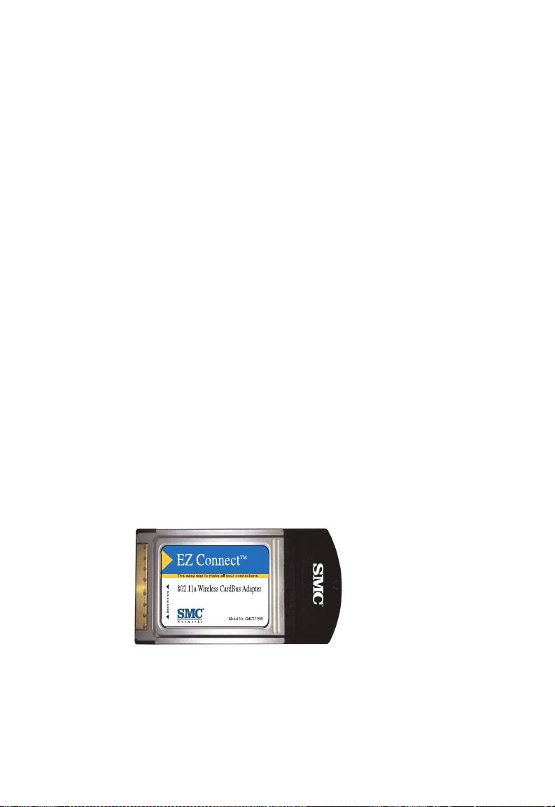
EZ Connect
802.11a Wireless CardBus Adapter
◆ 54 Mbps data rate (72 Mbps Turbo Mode): provides
alternative for wired LANs that can dramatically cut costs
◆ Coverage area up to 1650 ft
◆ Seamless connectivity to wired Ethernet LANs: augments
existing networks quickly and easily
◆ Supports 64/128/152-bit Wired Equivalent Privacy (WEP)
◆ Supports a wide range of operating systems
(Win98/NT/ME/2000/XP)
◆ Built-in antenna
◆ Easy installation
Installation Guide
SMC2735W
Page 2

Page 3

EZ Connect
User Guide
The easy way to make all your network connections
6 Hughes
Irvine, CA 92618
Phone: (949) 707-2400
December 2001
Pub. # 150000013700A
Part No: 01-111321-006
Page 4

Copyright
Information furnished by SMC Networks, Inc. (SMC) is believed to
be accurate and reliable. However, no responsibility is assumed by
SMC for its use, nor for any infringements of patents or other rights
of third parties which may result from its use. No license is granted
by implication or otherwise under any patent or patent rights of
SMC. SMC reserves the right to change specifications at any time
without notice.
Copyright © 2001 by
SMC Networks, Inc.
6 Hughes
Irvine, CA 92618
All rights reserved. Printed in Taiwan
Trademarks:
SMC is a registered trademark of SMC Networks, Inc. Other product and company names are
trademarks or registered trademarks of their respective holders.
Page 5

L
IMITED
Limited Warranty Statement: SMC Networks, Inc. (“SMC”) warrants its products
to be free from defects in workmanship and materials, under normal use and
service, for the applicable warranty term. All SMC products carry a standard 90-day
limited warranty from the date of purchase from SMC or its Authorized Reseller.
SMC may, at its own discretion, repair or replace any product not operating as
warranted with a similar or functionally equivalent product, during the applicable
warranty term. SMC will endeavor to repair or replace any product returned under
warranty within 30 days of receipt of the product.
The standard limited warranty can be upgraded to a Limited Lifetime* warranty by
registering new products within 30 days of purchase from SMC or its Authorized
Reseller. Registration can be accomplished via the enclosed product registration
card or online via the SMC web site. Failure to register will not affect the standard
limited warranty. The Limited Lifetime warranty covers a product during the Life of
that Product, which is defined as the period of time during which the product is an
“Active” SMC product. A product is considered to be “Active” while it is listed on
the current SMC price list. As new technologies emerge, older technologies become
obsolete and SMC will, at its discretion, replace an older product in its product line
with one that incorporates these newer technologies. At that point, the obsolete
product is discontinued and is no longer an “Active” SMC product. A list of
discontinued products with their respective dates of discontinuance can be found
at:
http://www.smc.com/index.cfm?action=customer_service_warranty.
All products that are replaced become the property of SMC. Replacement products
may be either new or reconditioned. Any replaced or repaired product carries
either a 30-day limited warranty or the remainder of the initial warranty, whichever
is longer. SMC is not responsible for any custom software or firmware,
configuration information, or memory data of Customer contained in, stored on, or
integrated with any products returned to SMC pursuant to any warranty. Products
returned to SMC should have any customer-installed accessory or add-on
components, such as expansion modules, removed prior to returning the product
for replacement. SMC is not responsible for these items if they are returned with the
product.
Customers must contact SMC for a Return Material Authorization number prior to
returning any product to SMC. Proof of purchase may be required. Any product
returned to SMC without a valid Return Material Authorization (RMA) number
clearly marked on the outside of the package will be returned to customer at
customer’s expense. For warranty claims within North America, please call our
toll-free customer support number at (800) 762-4968. Customers are responsible for
all shipping charges from their facility to SMC. SMC is responsible for return
shipping charges from SMC to customer.
W
ARRANTY
i
Page 6

L
IMITED WARRANTY
WARRANTIES EXCLUSIVE: IF AN SMC PRODUCT DOES NOT OPERATE AS
WARRANTED ABOVE, CUSTOMER’S SOLE REMEDY SHALL BE REPAIR OR
REPLACEMENT OF THE PRODUCT IN QUESTION, AT SMC’S OPTION. THE
FOREGOING WARRANTIES AND REMEDIES ARE EXCLUSIVE AND ARE IN LIEU
OF ALL OTHER WARRANTIES OR CONDITIONS, EXPRESS OR IMPLIED, EITHER
IN FACT OR BY OPERATION OF LAW, STATUTORY OR OTHERWISE, INCLUDING
WARRANTIES OR CONDITIONS OF MERCHANTABILITY AND FITNESS FOR A
PARTICULAR PURPOSE. SMC NEITHER ASSUMES NOR AUTHORIZES ANY OTHER
PERSON TO ASSUME FOR IT ANY OTHER LIABILITY IN CONNECTION WITH
THE SALE, INSTALLATION, MAINTENANCE OR USE OF ITS PRODUCTS. SMC
SHALL NOT BE LIABLE UNDER THIS WARRANTY IF ITS TESTING AND
EXAMINATION DISCLOSE THE ALLEGED DEFECT IN THE PRODUCT DOES NOT
EXIST OR WAS CAUSED BY CUSTOMER’S OR ANY THIRD PERSON’S MISUSE,
NEGLECT, IMPROPER INSTALLATION OR TESTING, UNAUTHORIZED ATTEMPTS
TO REPAIR, OR ANY OTHER CAUSE BEYOND THE RANGE OF THE INTENDED
USE, OR BY ACCIDENT, FIRE, LIGHTNING, OR OTHER HAZARD.
LIMITATION OF LIABILITY: IN NO EVENT, WHETHER BASED IN CONTRACT OR
TORT (INCLUDING NEGLIGENCE), SHALL SMC BE LIABLE FOR INCIDENTAL,
CONSEQUENTIAL, INDIRECT, SPECIAL, OR PUNITIVE DAMAGES OF ANY KIND,
OR FOR LOSS OF REVENUE, LOSS OF BUSINESS, OR OTHER FINANCIAL LOSS
ARISING OUT OF OR IN CONNECTION WITH THE SALE, INSTALLATION,
MAINTENANCE, USE, PERFORMANCE, FAILURE, OR INTERRUPTION OF ITS
PRODUCTS, EVEN IF SMC OR ITS AUTHORIZED RESELLER HAS BEEN ADVISED
OF THE POSSIBILITY OF SUCH DAMAGES.
SOME STATES DO NOT ALLOW THE EXCLUSION OF IMPLIED WARRANTIES OR
THE LIMITATION OF INCIDENTAL OR CONSEQUENTIAL DAMAGES FOR
CONSUMER PRODUCTS, SO THE ABOVE LIMITATIONS AND EXCLUSIONS MAY
NOT APPLY TO YOU. THIS WARRANTY GIVES YOU SPECIFIC LEGAL RIGHTS,
WHICH MAY VARY FROM STATE TO STATE. NOTHING IN THIS WARRANTY
SHALL BE TAKEN TO AFFECT YOUR STATUTORY RIGHTS.
* SMC will provide warranty service for one year following discontinuance from the
active SMC price list. Under the limited lifetime warranty, internal and external
power supplies, fans, and cables are covered by a standard one-year warranty from
date of purchase.
SMC Networks, Inc.
6 Hughes
Irvine, CA 92618
ii
Page 7

C
OMPLIANCES
FCC - Class B
This equipment has been tested and found to comply with the limits for a Class B digital
device, pursuant to Part 15 of the FCC Rules. These limits are designed to provide
reasonable protection against harmful interference in a residential installation. This
equipment generates, uses and can radiate radio frequency energy and, if not installed
and used in accordance with instructions, may cause harmful interference to radio
communications. However, there is no guarantee that the interference will not occur in
a particular installation. If this equipment does cause harmful interference to radio or
television reception, which can be determined by turning the equipment off and on, the
user is encouraged to try to correct the interference by one or more of the following
measures:
• Reorient the receiving antenna
• Increase the separation between the equipment and receiver
• Connect the equipment into an outlet on a circuit different from that to
which the receiver is connected
• Consult the dealer or an experienced radio/TV technician for help
Industry Canada - Class B
This digital apparatus does not exceed the Class B limits for radio noise emissions from
digital apparatus as set out in the interference-causing equipment standard entitled
“Digital Apparatus,” ICES-003 of the Department of Communications.
Cet appareil numérique respecte les limites de bruits radioélectriques applicables aux
appareils numériques de Classe B prescrites dans la norme sur le matériel brouilleur:
“Appareils Numériques,” NMB-003 édictée par le ministère des Communications.
iii
Page 8

C
OMPLIANCES
iv
Page 9

T
ABLE OF
EZ Connect™
802.11a Wireless CardBus Adapter . . . . . . . . . . . .1
Introduction . . . . . . . . . . . . . . . . . . . . . . . . . . . . . . . . . . . . . . 1
Package Checklist . . . . . . . . . . . . . . . . . . . . . . . . . . . . . . . . . . 2
Hardware Description . . . . . . . . . . . . . . . . . . . . . . . . . . . . . . . 2
Applications . . . . . . . . . . . . . . . . . . . . . . . . . . . . . . . . . . . . . . 3
LED Indicators . . . . . . . . . . . . . . . . . . . . . . . . . . . . . . . . . . . . . 4
System Requirement . . . . . . . . . . . . . . . . . . . . . . . . . . . . . . . . 5
Hardware Installation . . . . . . . . . . . . . . . . . . . . . . .6
Driver Installation . . . . . . . . . . . . . . . . . . . . . . . . . .8
Windows 98/2000/ME/XP Installation . . . . . . . . . . . . . . . 9
Installation for Windows NT 4.0 . . . . . . . . . . . . . . . . . . 17
Network Configuration and Planning . . . . . . . . .21
Network Topologies . . . . . . . . . . . . . . . . . . . . . . . . . . . . . . . 22
Ad Hoc Wireless LAN . . . . . . . . . . . . . . . . . . . . . . . . . . 22
Infrastructure Wireless LAN . . . . . . . . . . . . . . . . . . . . . . 23
Infrastructure Wireless LAN for Roaming Wireless PCs . . 24
C
ONTENTS
Configuration and Diagnostic Utility . . . . . . . . . .25
Utility Installation . . . . . . . . . . . . . . . . . . . . . . . . . . . . . . . . . 25
Using the Wireless LAN Utility . . . . . . . . . . . . . . . . . . . . . . . . 26
Troubleshooting . . . . . . . . . . . . . . . . . . . . . . . . . .31
Adapter Installation Problems . . . . . . . . . . . . . . . . . . . . . . . . . 31
Network Connection Problems . . . . . . . . . . . . . . . . . . . . . . . . 32
SMC Networks:
802.11a Wireless Product Maximum Distance Table . . . . . 33
Specifications . . . . . . . . . . . . . . . . . . . . . . . . . . . . .34
Terminology . . . . . . . . . . . . . . . . . . . . . . . . . . . . .38
v
Page 10

T
ABLE OF CONTENTS
vi
Page 11

EZ C
™
ONNECT
802.11a W
Introduction
SMC’s EZ Connect 802.11a Wireless CardBus Adapter is a 54 Mbps
(72 Mbps Turbo Mode) wireless network card that seamlessly
integrates with existing Ethernet networks to support applications
such as mobile users or temporary conferences. This solution
offers fast, reliable wireless connectivity with considerable cost
savings over wired LANs (which include long-term maintenance
overhead for cabling). Just plug wireless cards into your notebook
PCs and start networking.
Using this card in conjunction with SMC’s EZ Connect SMC2755W
802.11a Wireless Access Point, you can create an instant network
that integrates seamlessly with 10/100 Mbps Ethernet LANs.
Moreover, moving or expanding your network is as easy as
moving or installing additional access points — no wires!
IRELESS
C
ARDBUS
A
DAPTER
1
Page 12
EZ C
ONNECT
™ 802.11A W
IRELESS CARDBUS ADAPTER
Package Checklist
The EZ Connect Wireless CardBus Adapter package includes:
• 1 EZ Connect 802.11a Wireless CardBus Adapter (SMC2735W)
• 1 Driver and Utility CD ROM
•This User Guide
Please register this product and upgrade product warranty at:
www.smc.com.
Please inform your dealer if there are any incorrect, missing or
damaged parts. If possible, retain the carton, including the original
packing materials. Use them again to repack the product in case
there is a need to return it for repair.
Hardware Description
SMC’s EZ Connect 802.11a Wireless CardBus Adapter is fully
compliant with 802.11a wireless networking as defined in IEEE
802.11a. It can be installed in any notebook with a CardBus slot.
Support is provided for Windows 98/ME/2000/NT4.0/XP.
2
Page 13

EZ C
ONNECT
™ 802.11A W
IRELESS CARDBUS ADAPTER
Applications
EZ Connect Wireless products offer a fast, reliable, cost-effective
solution for wireless client access to the network in applications
such as:
• Remote access to corporate network information
E-mail, file transfer and terminal emulation
• Difficult-to-wire environments
Historical or old buildings, asbestos installations and open
areas where wiring is difficult to employ
• Frequently changing environments
Retailers, manufacturers and banks which frequently rearrange
the workplace or change location
• Temporary LANs for special projects or peak times
Trade shows, exhibitions and construction sites which need
temporary setup for a short time period. Retailers, airline and
shipping companies which need additional workstations for a
peak period. Auditors who require workgroups at customer
sites.
• Access to databases for mobile workers
Doctors, nurses, retailers, or white-collar workers who need
access to databases while being mobile in a hospital, retail
store or an office campus.
•SOHO (Small Office and Home Office) users
SOHO users who need easy and quick installation of a small
computer network.
3
Page 14
EZ C
ONNECT
™ 802.11A W
IRELESS CARDBUS ADAPTER
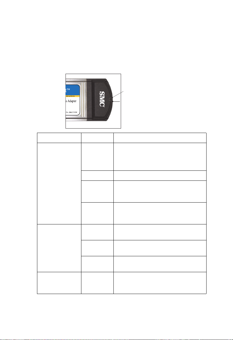
LED Indicators
The SMC2735W includes two status LED indicators, as described in
the following figure and table.
Power LED
Network LED
LED Condition Status
Power On Awake from power save. (The
CardBus Adapter automatically enters
this state after exit from power save
mode and before any other activity.)
Off No Power.
Slow
Flashing
Fast
Flashing
Network Off Neither associated nor looking for
Slow
Flashing
Fast
Flashing
Alternate
Power/Network
Alternate
Flashing of
both LEDs
Power save mode - or indicates
association with no activity (if flashing
together with Network LED).
Indicates associated with network
activity. (Flashing together with
Network LED.)
association.
Associated with no activity. (Flashes
together with Power LED.)
Associated with network activity.
(Flashes together with Power LED.)
Looking for a network but no activity.
4
Page 15

EZ C
ONNECT
™ 802.11A W
IRELESS CARDBUS ADAPTER
System Requirement
Before you install the EZ Connect 802.11a Wireless CardBus
Adapter, check your system for the following requirements:
• A computer with a CardBus slot
• Windows 98/NT4.0/ME/2000/XP (Have the Windows
installation CD-ROM ready for use during installation)
• A minimum of 10 Mbytes of free disk space for installing the
driver and utility program
• Other IEEE 802.11a-compliant devices installed in your service
area (such as the SMC2755W Wireless 802.11a Access Point)
5
Page 16

H
ARDWARE INSTALLATION
H
ARDWARE INSTALLATION
1. Turn your computer on and boot to your operating system.
2. Find an available CardBus slot in your computer.
3. With the EZ Connect 802.11a Wireless CardBus Adapter 68-pin
connector facing the CardBus slot and the EZ Connect 802.11a
Wireless CardBus Adapter label facing up, slide the card
completely into the CardBus slot as shown below.
Note: The CardBus slot allows you to “hot swap” the CardBus
Adapter at any time, even when your computer is
powered on.
4. For Windows 98/NT4.0/ME/2000/XP, CardBus specification is
required. Please check the documents for your CardBus
Adapter driver before installing the software driver for the
SMC2735W.
5. Install the appropriate network driver for your operating
system. Drivers can be found on the CD ROM. See “Driver
Installation” on page 8 for more information.
6
Page 17

H
ARDWARE INSTALLATION
6. Install the EZ Connect Wireless 802.11a CardBus Configuration
Utility for your wireless CardBus Adapter. The Setup.exe file
can be found on the CD ROM. See “Configuration and
Diagnostic Utility” on page 25 for more information.
7
Page 18

D
RIVER INSTALLATION
D
RIVER INSTALLATION
The folder labeled “Driver” on the CD ROM that comes with the
package contains all the software drivers available for the EZ
Connect 802.11a Wireless CardBus Adapter. Select the driver you
need for your system and refer to this guide for the installation and
configuration procedure. Any new or updated drivers can be
downloaded from SMC’s Web site at:
http://www.smc.com.
You may find that the instructions in this chapter do not exactly
match your version of Windows. This is because these steps and
screenshots were created from Windows 2000. Windows 98,
Windows XP and Windows Millennium Edition are similar, but not
identical, to Windows 2000.
8
Page 19

D
RIVER INSTALLATION
Windows 98/2000/ME/XP Installation
1. Insert the CardBus into a standard CardBus slot in your
notebook.
2. Windows 98/2000/ME/XP will automatically detect the new
hardware and prompt you to install the driver. Click “Next” to
find the driver.
9
Page 20

D
RIVER INSTALLATION
3. Insert the CD ROM labeled “SMC2735W/SMC2755W Driver/
Utility/Documentation CD,” specify the location
“D:\Driver\Win2K (or Win98...)” and click “Next.”
10
Page 21

4. Click “Next” to copy files from the CD-ROM.
5. Click “Finish” to end the installation.
D
RIVER INSTALLATION
11
Page 22

D
RIVER INSTALLATION
6. To communicate with SMC EZ Connect 802.11a wireless
devices, you may need to configure the CardBus Adapter.
From the “Start” menu select “Settings” ” then click on “Control
Panel.”
7. Double click on the “SMC NIC Configuration” icon
12
Page 23

D
RIVER INSTALLATION
8. You may either modify the default settings or create a new
configuration profile. To modify the default settings, click
“Modify.” To create a new configuration profile, click “New.”
13
Page 24

D
RIVER INSTALLATION
9.
Configuration Name - Enter the desired profile name.
Network Name (SSID) - Set the “SSID” (Service Set ID) to the
same as that used by the ad hoc workgroup or access point
you want to connect to. (The SMC2755W access point default
is ANY.)
14
Note: The SSID is upper/lower case sensitive and can
consist of up to 32 alphanumeric characters.
Network Connection - Set “Network Connection” to
“Ad Hoc” or “AP (Infrastructure)” depending on the type of
network you want to connect to. (See page 21.)
Turbo Mode - Enable “Turbo Mode” to enhance performance
to 72Mbps (Default: Disabled). Please note that when the
Turbo Mode is enabled for the CardBus Adapter, it must also
be enabled for the Access Point.
Page 25

D
RIVER INSTALLATION
Power Saving Mode - Enable the “Power Saving” mode to
reduce power loading. (Default: Normal)
Locally Administered Address - Check this checkbox if you
wish to set your own MAC address for the Cardbus Adapter. A
MAC address consists of 12 hexadecimal numbers.
10. Click “OK” when you have finished the configuration profile.
This returns you to the “SMC NIC Configuration” dialog box.
The profile can be modified by selecting the profile name from
the “Configuration List” and clicking on “Modify.”
11. Wired Equivalent Privacy (WEP) is implemented in this device
to prevent unauthorized access to your wireless network. The
EZ Connect 802.11a Wireless CardBus Adapter supports
“Shared Key” encryption with key lengths from the standard
64-bit, industry standard 128-bit, to the extended 152-bit. In
addition to the standard WEP key, a per-station unique key is
also supported. For more secure data transmission, you may
set the WEP to ensure network security. All wireless devices
must have the same Key ID values to communicate.
15
Page 26

D
RIVER INSTALLATION
To enter security keys click on the “Security” tab in the
“Network Configuration Settings” screen and check “Enable
Security.”
Note: 64-Bit Manual Entry - Each Key ID contains 10 HEX digits.
128-Bit Manual Entry - Each Key ID contains 26 HEX
digits.
152-Bit Manual Entry - Each Key ID contains 32 HEX
digits.
12. Click “Close” in the Network dialog box and the system will
restart your computer.
13. To add protocols after installation, go to the “Control Panel”
and double-click “Network.”
16
Page 27

D
RIVER INSTALLATION
14. Click “Add” to install the network protocols you want to use,
such as IPX/SPX, NetBEUI or TCP/IP. If you install TCP/IP, be
sure to set the appropriate Gateway, DNS Server, and Domain
for your network. If you install an IPX/SPX-compatible
protocol, then you also need to install the Client for NetWare
Networks.
15. Click “File and Print Sharing” to share files or printers.
16. Click “Close” in the Network dialogue box and the system will
restart your computer.
Installation for Windows NT 4.0
1. Insert the CardBus into a standard CardBus slot in your
notebook.
2. From the desktop, select “Settings” and click on “Control
Panel.”
17
Page 28

D
RIVER INSTALLATION
3. Double click on “Network.”
4. Click “Adapters,” and then click the “Add” button on the
Network dialog box.
18
Page 29

D
RIVER INSTALLATION
5. Windows NT will present a list of all its supported adapters.
Click “Have Disk” to continue.
6. Windows NT will ask for the drive/path containing the
SMC2735W Windows NT drivers. Insert the CD ROM labeled
“SMC2735W/SMC2755W Driver/Utility/Documentation CD,”
specify the location “D:\Driver\WinNT” and click “OK.”
7. Windows NT will attempt to locate an INF file in the specified
path. If you have entered the path name correctly, Windows
NT should copy the appropriate drivers to the Windows NT
system. Acknowledge the selection by clicking “OK.”
8. The Adapter Setup dialog box will appear. Configure the card
as described below, and click “OK.”
I/O Base - Default: 240 (Check for available resources under
Windows NT Diagnostics.)
19
Page 30

D
RIVER INSTALLATION
IRQ Level - Select 9, 10 or 11. (Check for available resources
under Windows NT Diagnostics.)
Mode - Set to “AdHoc” or “Infrastructure,” depending on the
type of network you want to connect to (see page 21).
SSID - Set the “SSID” identifier to the same as that used by the
ad hoc workgroup or access point you want to connect to.
(SMC2755W Access point default: ANY)
20
Page 31

N
ETWORK
N
ETWORK CONFIGURATION AND PLANNING
C
ONFIGURATION
AND
SMC’s EZ Connect Wireless Solution supports stand-alone wireless
network configuration, as well as an integrated configuration with
10/100 Mbps Ethernet LANs.
The SMC2735W can be configured as:
• Ad hoc for departmental or SOHO LANs
• Infrastructure for enterprise LANs
P
LANNING
21
Page 32

N
ETWORK CONFIGURATION AND PLANNING
Network Topologies
Ad Hoc Wireless LAN
An ad hoc wireless LAN consists of a group of computers, each
equipped with one wireless adapter, connected via radio signals as
an independent wireless LAN. Computers in a specific ad hoc
wireless LAN must therefore be configured to the same radio
channel.
An ad hoc wireless LAN can be used for a branch office or SOHO
operation.
Ad Hoc Wireless LAN
Notebook with
Wireless USB Adapter
22
Notebook with
Wireless PC Card
PC with Wireless
PCI Adapter
Page 33

N
ETWORK CONFIGURATION AND PLANNING
Infrastructure Wireless LAN
The SMC2735W can also provide access to a wired LAN for
wireless workstations. An integrated wired/wireless LAN is called
an infrastructure configuration. A Basic Service Set (BSS) consists
of a group of wireless PC users, and an access point that is directly
connected to the wired LAN. Each wireless PC in this BSS can talk
to any computer in its wireless group via a radio link, or access
other computers or network resources in the wired LAN
infrastructure via the access point.
The infrastructure configuration not only extends the accessibility
of wireless PCs to the wired LAN, but also increases the effective
wireless transmission range for wireless PCs by passing their signal
through one or more access points.
A wireless infrastructure can be used for access to a central
database, or for connection between mobile workers, as shown in
the following figure.
Wired LAN Extension
to Wireless Adapters
File
Server
Desktop PC
Switch
Notebook with Wireless
PC Card Adapter
Access Point
PC with Wireless
PCI Adapter
23
Page 34

N
ETWORK CONFIGURATION AND PLANNING
Infrastructure Wireless LAN for Roaming Wireless PCs
The Basic Service Set (BSS) is the communications domain for
each EZ Connect Wireless Access Point. For wireless PCs that do
not need to support roaming, set the domain identifier (SSID) for
the wireless card to the SSID of the access point to which you
want to connect. Check with your administrator for the SSID of the
access point to which he wants you to connect.
A wireless infrastructure can also support roaming for mobile
workers. More than one access point can be configured to create
an Extended Service Set (ESS). By placing the access points so that
a continuous coverage area is created, wireless users within this
ESS can roam freely. All SMC wireless network cards and adapters
and SMC2755W Wireless access points within a specific ESS must
be configured with the same SSID.
File
Server
Desktop PC
Switch
Notebook with Wireless
PC Card Adapter
24
Switch
PC with Wireless
PC I Adapter
Access Point
Notebook with Wireless
PC Card Adapter
<BSS1>
Access Point
<ESS>
Seamless Roaming
<BSS2>
Page 35

C
ONFIGURATION AND DIAGNOSTIC UTILITY
C
ONFIGURATION AND
D
IAGNOSTIC
SMC’s EZ Connect Wireless CardBus Adapter provides free
optional management software for quick network configuration
and easy diagnostics. The CD labeled “SMC2735W/SMC2755W
Driver/Utility/Documentation CD,” that comes with the package,
contains a Utility Program that has user-friendly interface for
configuring the card.
U
Utility Installation
To install the utility software:
1. Insert the CD-ROM in your PC’s CD player.
2. Select “Run...” from Windows “Start” menu bar.
TILITY
3. Click on “Browse...” to locate the setup file of this program.
4. Then click on “OK” to run the setup program.
25
Page 36

C
ONFIGURATION AND DIAGNOSTIC UTILITY
5. Follow the on-screen instructions to finish installation.
Using the Wireless LAN Utility
Once the installation is completed, the configuration utility can be
accessed from the “Start” menu, as shown below.
This configuration software includes the following functions:
26
Page 37

C
ONFIGURATION AND DIAGNOSTIC UTILITY
General Information Screen
When you start the CardBus utility, general information for the
SMC2735W is shown under the first tab of the utility windows as
shown below.
Frame Statistics
This, and the following dialog box, provides statistics on frames
sent and received by the CardBus Adapter
27
Page 38

C
ONFIGURATION AND DIAGNOSTIC UTILITY
Transmit Retries
28
Page 39

C
ONFIGURATION AND DIAGNOSTIC UTILITY
Station
This screen displays information on all access points on the
network. If “Station Status” is “Associated,” the Cardbus Adapter is
linked to an access point and information on this access point is
shown in the top part of the screen.
Channel - The radio channel through which the Access Point
communicates to PCs in its BSS. (Default: “52” for the USA and
“38” for Japan.) A Basic Service Set (BSS) consists of a group of
wireless PC users, and an access point that is directly connected to
the wired LAN. Note that the channel for wireless clients is
automatically set to the same as that used by the access point to
which it is linked.
Frequency - The radio frequency at which the CardBus Adapter is
communicating with the Access Point.
BSSID - The MAC address of the access point.
SSID - Service Set ID. (See “Infrastructure Wireless LAN for
Roaming Wireless PCs” on page 24.)
29
Page 40

C
ONFIGURATION AND DIAGNOSTIC UTILITY
Driver
This dialog box gives information on how the operating system
interacts with the CardBus Adapter.
30
Page 41

T
ROUBLE SHOOTING
T
ROUBLESHOOTING
Check the following troubleshooting items before contacting SMC
Technical Support.
Adapter Installation Problems
If your computer cannot find the EZ Connect Wireless CardBus
Adapter or the network driver does not install correctly, check the
following:
• Make sure the adapter is securely seated in the CardBus slot.
When you insert the wireless adapter into the notebook’s slot,
a click should be heard if the adapter is properly inserted.
Check for any hardware problems, such as physical damage to
the card’s connector.
• Try the card in another CardBus slot. If this also fails, test your
computer with another SMC2735W wireless card that is known
to operate correctly.
• When operating under Windows NT, make sure a CardBus
adapter and socket services driver is installed in your computer.
Also check for resource conflicts using the Windows NT
Diagnostics utility.
• Make sure your computer is using the latest BIOS.
• If there are other network adapters in the computer, they may
be causing conflict, remove all other adapters from the
computer and test the wireless adapter separately.
• Check for a defective computer or CardBus slot by trying the
adapter in another computer that is known to operate correctly.
31
Page 42

T
ROUBLESHOOTING
Network Connection Problems
If the Network LED on the CardBus adapter does not light, or if
you cannot access any network resources from the computer.
Check the following:
• Make sure the correct software driver is installed for your
operating system. If necessary, try reinstalling the driver.
• Make sure the computer and other network devices are
receiving power.
• The access point you are using may be defective. Try to use
another access point.
• If you cannot access a Windows or NetWare service on the
network, check that you have enabled and configured the
service correctly. If you cannot connect to a particular server,
ensure that you have access rights and a valid ID and password.
• If you cannot access the Internet, ensure that you have
configured your system for TCP/IP.
If your wireless station cannot communicate with a computer in
the Ethernet LAN when configured for infrastructure mode, check
the following:
• Make sure the access point that the station is associated with is
powered on.
• Make sure your wireless station is configured with the same
operating radio channel as the access point.
• If you still cannot connect, change the access point and all the
stations within the BSS to another radio channel.
• Make sure the BSSID is the same as the access point for a
station with roaming disabled, or the SSID is the same as the
access point for a station with roaming enabled.
32
Page 43

T
ROUBLE SHOOTING
SMC Networks: 802.11a Wireless Products Maximum Distance Table
Important Notice
Maximum distances posted below are actual tested distance
thresholds. However, there are many variables such as barrier
composition and construction as well as local environmental
interference, that may impact actual distances and cause you to
experience distance thresholds far lower than those posted below.
If you have any questions or comments regarding the features or
performance of this product, or if you would like information
regarding SMC’s full line of wireless products, you can visit SMC’s
Web site at www.smc.com or you can call SMC toll-free at
800.SMC.4YOU. SMC Networks stands behind every product sold
with a 30 day satisfaction guarantee and a limited-lifetime
warranty.
SMC 802.11a Wireless Products Maximum Distance Table
Speed and Distance Ranges
Environmental
Condition
Outdoor
Environment
72 Mbps 54 Mbps 48 Mbps 36 Mbps 24 Mbps 18 Mbps 12 Mbps 9 Mbps 6 Mbps
35 m
40 m
221 m
251 m
322 m
350 m
382 m
453 m
1
(115 ft)
(132 ft)
(726 ft)
(825 ft)
(1056 ft)
(1155 ft)
(1254 ft)
(1485 ft)
503 m
(1650 ft)
Indoor
Environment
12 m
18 m
25 m
30 m
35 m
2
(40 ft)
(60 ft)
(82 ft)
(99 ft)
Notes: 1. Outdoor Environment: A line-of-sight environment with no
interference or obstruction between Access Point and users.
2. Indoor Environment: A typical office or home environment with floor
to ceiling obstructions between Access Point and users.
(115 ft)
40 m
(132 ft)
45 m
(149 ft)
48 m
(157 ft)
50 m
(165 ft)
33
Page 44

S
PECIFICATIONS
Functional Criteria
Data Rate
Normal Mode: 6, 9, 12, 18, 24, 36, 48, 54 Mbps
Turbo Mode: 12, 18, 24, 36, 48, 72 Mbps
Standard
IEEE 802.11a - wireless
Operating Range
Up to 1650 ft (503 m)
Radio Signal
Signal Type
Orthogonal Frequency Division Multiplexing (OFDM)
Operating Frequency
5.15 ~ 5.25 GHz (lower band) for US/Canada, Japan
5.25 ~ 5.35 GHz (middle band) for US/Canada
Sensitivity
S
PECIFICATIONS
34
Modulation/Rates Sensitivity (dBm)
BPSK (6 Mbps) -85
BPSK (9 Mbps) -84
QPSK (12 Mbps) -83
QPSK (18 Mbps) -81
16 QAM (24 Mbps) -78
16 QAM (36 Mbps) -74
64 QAM (48 Mbps) -69
64QAM(54 Mbps) -65
BPSK Turbo (12 Mbps) -82
BPSK Turbo (18 Mbps) -81
QPSK Turbo (24 Mbps) -80
Page 45

QPSK Turbo (36 Mbps) -78
16 QAM Turbo (48 Mbps) -75
16 QAM Turbo (72 Mbps) -71
Modulation
S
PECIFICATIONS
Modulation 5.15-5.25 GHz
(dBm)
BPSK(6 Mbps) 16 20
BPSK(9 Mbps) 16 20
QPSK(12 Mbps) 16 19
QPSK(18 Mbps) 16 19
16 QAM(24 Mbps) 16 18
16 QAM(36 Mbps) 16 18
64 QAM(48 Mbps) 16 16
64 QAM(64 Mbps) 14 14
BPSK Turbo(12 Mbps) 16 20
BPSK Turbo(18 Mbps) 16 20
QPSK Turbo(24 Mbps) 16 19
QPSK Turbo(36 Mbps) 16 19
16 QAM Turbo(48 Mbps) 16 18
16 QAM Turbo(72 Mbps) 16 18
5.25-5.35 GHz
(dBm)
Physical Characteristics
Input Voltage
3.3 V
Power Consumption
Base Mode, Uninitialized, 37 mw
TX, 1657 mw
RX, 1247 mw
35
Page 46

S
PECIFICATIONS
Idle/Listening, 1238 mw, Sleep - 40 mw
Weig h t
50 g (4.8 oz)
Dimensions
11.5 x 5.3 cm (4.53 x 2.09 in.)
Antenna
Built-in side-stem antenna
LED Indicators
Power, Network
Host Interface
68-pin connector to CardBus slot
Environmental
Temperature
32 to 140 °F/ 0 to 50 °C (operating)
32 to 158 °F/ 0 to 70 °C (storage)
Humidity
5 to 80% (non-condensing)
Vibration/Shock/Drop
IEC 68-2-34, IEC 68-2-27, IEC 68-2-32
Emissions
FCC Class B
Safety
CSA/NTRL (CSA 22.2 No. 950 & UL 1950)
Vibration/Shock/Drop
IEC 68-2-34/IEC 68-2-32
Standards
IEEE 802.11a
Software Drivers
Windows 98
Windows 2000
Windows NT 4.0
36
Page 47

Windows XP
Windows ME
S
PECIFICATIONS
37
Page 48

T
ERMINOLOGY
T
ERMINOLOGY
The following is a list of terminology that is used in this document.
Access Point – An internetworking device that seamlessly
connects wired and wireless networks.
Ad hoc – An ad hoc wireless LAN is a group of computers each
with LAN adapters, connected as an independent wireless LAN.
Backbone – The core infrastructure of a network. The portion of
the network that transports information from one central location
to another central location where it is unloaded onto a local
system.
Base Station – In mobile telecommunications, a base station is the
central radio transmitter/receiver that maintains communications
with the mobile radiotelephone sets within its range. In cellular
and personal communications applications, each cell or micro-cell
has its own base station; each base station in turn is
interconnected with other cells’ bases.
BSS – BSS stands for “Basic Service Set.” It is an Access Point and
all the LAN PCs that are associated with it.
CSMA/CA – Carrier Sense Multiple Access with Collision
Avoidance.
ESS – ESS (ESS-ID, SSID) stands for “Extended Service Set.” More
than one BSS is configured to become an Extended Service Set.
LAN mobile users can roam between different BSSs in an ESS
(ESS-ID, SSID).
38
Page 49

T
ERMINOLOGY
Ethernet – A popular local area data communications network,
which accepts transmission from computers and terminals.
Ethernet operates on a 10 Mbps base band transmission rate, using
a shielded coaxial cable or over shielded twisted pair telephone
wire.
Infrastructure – An integrated wireless and wired LAN is called
an Infrastructure configuration.
Roaming – A wireless LAN mobile user moves around an ESS and
maintains a continuous connection to the Infrastructure network.
RTS Threshold – Transmitters contending for the medium may
not be aware of each other. RTS/CTS mechanism can solve this
“Hidden Node Problem.” If the packet size is smaller than the
preset RTS Threshold size, the RTS/CTS mechanism will NOT be
enabled.
WEP – “Wired Equivalent Privacy” is based on the use of 64-bit,
128-bit or 152-bit keys and the popular RC4 encryption algorithm.
Wireless devices without a valid WEP key will be excluded from
network traffic.
39
Page 50

T
ERMINOLOGY
40
Page 51

Page 52

FOR TECHNICAL SUPPORT, CALL:
From U.S.A. and Canada (24 hours a day, 7 days a week)
(800) SMC-4-YOU; (949) 707-2400; (949) 707-2460 (Fax)
From Europe (8:00 AM - 5:30 PM UK Greenwich Mean Time)
44 (0) 1188 748740; 44 (0) 1189 748741 (Fax)
INTERNET
E-mail address:
techsupport@smc.com
tech.support@smc-europe.com
Driver updates:
http://www.smc.com/index.cfm?action=tech_support_drivers_downloads
World Wide Web:
http://www.smc.com/
FOR LITERATURE OR ADVERTISING RESPONSE, CALL:
U.S.A. and Canada: (800) SMC-4-YOU; Fax (949) 707-2460
Spain: 34-93-477-4920; Fax 34-93-477-3774
UK: 44 (0) 1188 748700; Fax 44 (0) 1189 748701
Southern Europe: 33 (1) 41 38 32 32; Fax 33 (1) 41 38 01 58
Central/Eastern Europe: 49 (0) 89 92861-130; Fax 49 (0) 89 92861-230
Nordic: 46 (0) 86870700; Fax 46 (0) 8876262
Middle East: 971-48818410; Fax 971-48817993
South Africa: 27-11-314-1133; Fax 27-11-314-9133
PRC: 86-10-6235-4958; Fax 86-10-6235-4962
Taiwan: 886-2-2659-9669; Fax 886-2-2659-9666
Asia Pacific: (65) 238 6556; Fax (65) 238 6466
Korea: 82-2-553-0860; Fax 82-2-553-7202
Japan: 81-45-224-2329; Fax 81-45-224-2344
Australia: 61-2-9416-0437; Fax 61-2-9416-0474
India: 91-22-8204437; Fax 91-22-8204443
6 Hughes
Irvine, CA 92618
Phone: (949) 707-2400
Model Number: SMC2735W
Publication Number: 150000013700A E122001-R01
 Loading...