

Page 1

TM
EZ Connect
Wireless Bridge
K Protocol-independent networking functionality
K 11 Mbps data rate per channel: provides alternative
wired LANs that can dramatically cut costs
K Seamless connectivity to wired Ethernet LANs
augments existing networks quickly and easily
K Direct Sequence Spread-Spectrum (DSSS)
technology provides robust and secure wireless
connection
K Easy installation
K Omni-directional antenna
User Guide
SMC 2682W
SMC2652W
Page 2

Copyright
Information furnished by SMC Networks, Inc.
(SMC) is believed to be accurate and reliable.
However, no responsibility is assumed by SMC for
its use, nor for any infringements of patents or
other rights of third parties which may result from
its use. No license is granted by implication or
otherwise under any patent or patent rights of
SMC. SMC reserves the right to change
specifications at any time without notice.
Copyright © 2001 by
SMC Networks, Inc.
All rights reserved. Printed in Taiwan
Irvine, California.
Trademarks
SMC is a registered trademark; and EZ Connect
and EZ Hub are trademarks of SMC Networks, Inc.
Other product and company names are trademarks
or registered trademarks of their respective
holders.
Limited Lifetime Warranty
Complete warranty information for all SMC
products is available on SMCs Web site at www.
smc.com.
Page 3

EZ CONNECT
WIRELESS BRIDGE
SMC2682W
SMCs EZ Connect Wireless Bridge is an 11
Mbps wireless bridge that allows the connections
of two or more remote Ethernet LANs into a
single virtual LAN. Workstations on each of the
remote LANs may communicate with each other
as though they were on the same physical LAN.
The wireless bridge can also function as an
Access Point and provide transparent, wireless
data communications between the wired LAN
(and/or within the wireless Network) and fixed,
portable or mobile devices equipped with a
wireless adapter employing the same
modulation.
This solution offers fast, reliable wireless
connectivity with considerable cost savings over
wired LANs (which include long-term
maintenance overhead for cabling.)
TM
Page 4

Package Checklist
The EZ Connect Wireless Bridge package
includes:
1 EZ Connect Wireless Bridge (SMC2682W)
1 antenna (dipole, omni-directional)
1 DC power adapter
1 utility diskette
This User Guide
Please register this product and upgrade the
product warranty at www.smc.com.
Please inform your dealer if there are any
incorrect, missing or damaged parts. If possible,
retain the carton, including the original packing
materials. Use them again to repack the product
in case there is a need to return it.
Hardware Description
Ethernet Compatibility:
SMCs EZ Connect Wireless Bridge can attach
directly to 10BaseT (Twisted Pair) Ethernet LAN
segments. These segments must conform to
IEEE 802.3 specification.
The Bridge appears as an Ethernet node and
performs a routing function by moving packets
from the wired LAN to remote workstations on
the Wireless infrastructure.
Radio Characteristics:
The Wireless Bridge uses a radio modulation
technique known as Direct Sequence Spread
Spectrum transmission (DSSS, CSMA/CA). It
operates in the 2.4 GHz license-free Industrial
Scientific and Medical (ISM) band. Data is
transmitted over a half-duplex radio channel
operating at up to 11 Megabits per second
(Mbps).
Page 5

Applications
The EZ Connect Wireless products offer a fast,
reliable, cost-effective solution for wireless/
Ethernet client access to the network in
applications such as:
Remote access to corporate network
information
E-mail, file transfer and terminal emulation
Difficult-to-wire environments
Historical or old buildings, asbestos
installations and open areas where wiring is
difficult to employ
Frequently changing environments
Retailers, manufacturers and banks which
frequently rearrange the workplace or change
location
Temporary LANs for special projects or
peak times
Trade shows, exhibitions and construction
sites which need temporary setup for a short
time period. Retailers, airline and shipping
companies which need additional
workstations for a peak period. Auditors
who require workgroups at customer sites.
Access to databases for mobile workers
Doctors, nurses, retailers, or white-collar
workers who need access to databases while
being mobile in a hospital, retail store or an
office campus.
SOHO (Small Office and Home Office)
users
SOHO users who need easy and quick
installation of a small computer network
functions.
Building-to-Building connectivity
Connect discreet sites into a single LAN,
even when theyre separated by obstacles
such as freeways, railroads, or bodies of water
that are practically insurmountable for
copper and fiber-optic cable.
Page 6
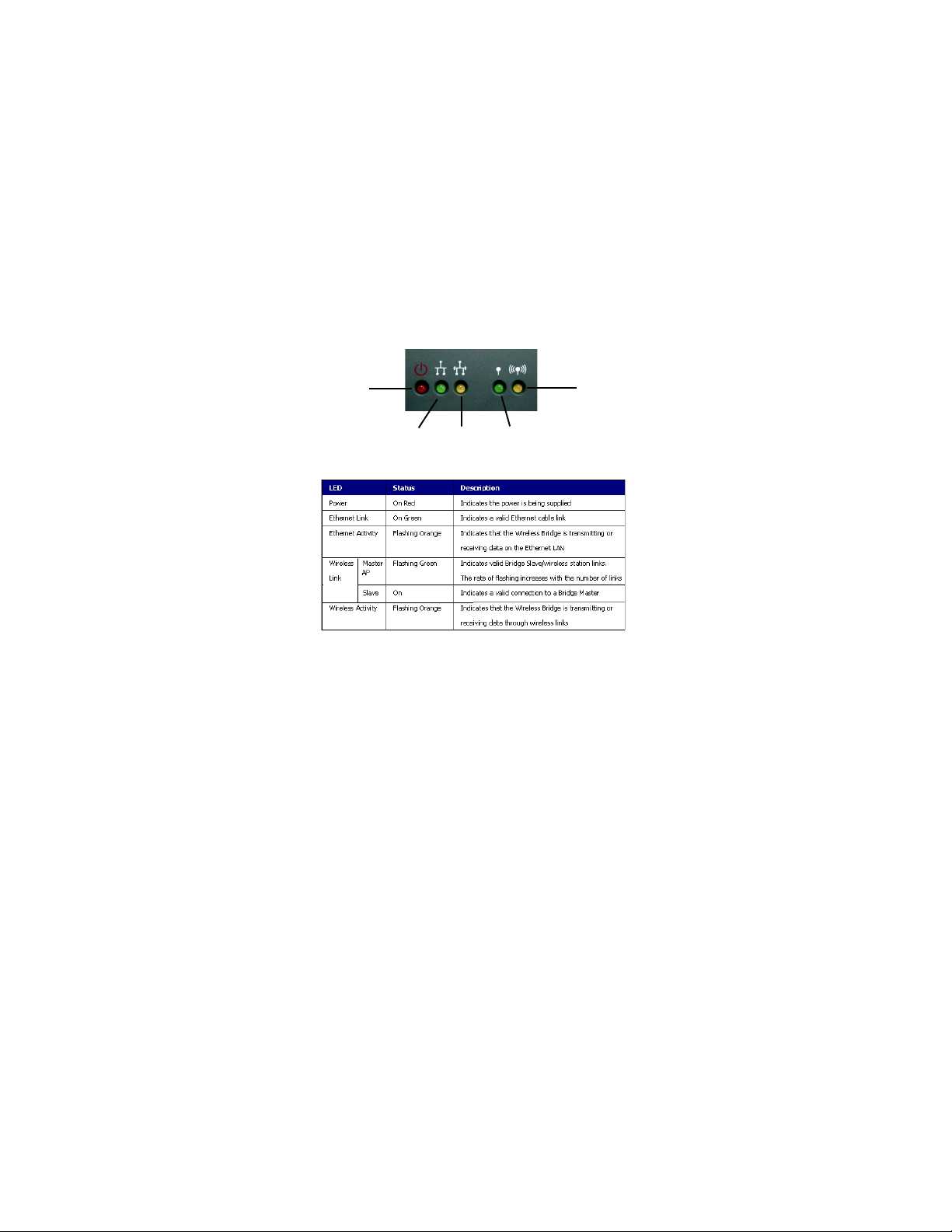
LED Indicators
The EZ Connect Wireless Bridge includes five
status LED indicators, as described in the
following figure and table.
Power
Ethernet
Link
Ethernet
Activity
Wireless
Link
System Requirements
Before you install the EZ Connect Wireless
Access Point, be sure you can meet the following
requirements:
An A/C power outlet (100~240V, 50~60Hz)
which will supply power for the access point
An available RJ-45 (UTP) port on a 10BASE-
T Ethernet hub or switch
802.11 compliant wireless ethernet adapters
with TCP/IP compatible protocol installed
Web Browser for configuration
Wireless
Activity
Page 7

INSTALLATION
1. Select the Site - Choose a proper place for
your SMC2682W Wireless Bridge. In
general, the best location is at the center of
your wireless coverage area, within line of
sight to all wireless devices.
2. Attach the Antenna - Screw the antenna into
the antenna connector (ANTENNA) on the
back panel. Proper placement will improve
performance. Try to place the Bridge in a
position that can best cover its BSS (refer to
page 13). Normally, the higher you place
the antenna, the better the performance.
RJ-45 Connector
Antenna Connector
RS-232 Port
Reset Button
3. Connect the Ethernet Cable - The
SMC2682W can be wired to a 10 BASE-T
Ethernet with a network device such as a
hub or a switch.Connect into the RJ-45
connector socket on the back panel with
category 3, 4 or 5 UTP Ethernet cable and
an RJ-45 connector.
4. Connect the Power Cable - Connect the
power adapter cable to the 9V DC power
Socket on the rear panel.
Warning: USE ONLY the power adapter
supplied with the SMC2682W.
Otherwise, the product may be
damaged.
DC 9V Power Cable
Page 8

CONFIGURATION
The diskette labeled Utility Diskette that
comes with the package contains a utility
program for the EZ Connect Wireless Bridge.
Any updates can be downloaded from SMCs
Web site at
http://www.smc.com.
Warning: Back up your utility diskette and use
the copy as the working diskette to
protect the original from accidental
damage.
The SMC2682W can be configured over an
Ethernet network using RJ-45 cable. You may
connect the SMC2682W to a network device
such as a hub or switch. Then, run the utility
program, and configure the SMC2682W
remotely as described below.
Windows NT/95/98/2000/ME
Installation
1. Insert the SMC2682W utility disk into the
floppy drive on your PC, and then enter the
following command: A:\utility\setup.
Follow the on-screen instructions to install
the utility program.
2. When you run the installed utility, click on
AP/Bridge and then select Scan from
the menu. The program will then detect all
the SMC2682W Bridges on the network.
Page 9

3. From the list of detected devices, select and
double-click on the unit you want to
configure. The Assign Temporary IP
Address dialog box will appear. The utility
will display IP information based on what it
gathered from the network settings on your
computer. You may manually change it if
you prefer some other settings, or click OK
if youd like to use the IP information the
utility generated.
4. A second box will pop up, informing you
that the IP address youve assigned is only
temporary. Click OK and the utility will
appear again, listing the device again, this
time with IP information.
Page 10

5. From the list, again select and double click
on the unit you want to configure. This
time the web browser page will appear as
follows::
6. Enter the password WLAN_BRIDGE
and click Login. This will take you to
the home page.
7. Click on Bridge Information MIB,
Bridge Control MIB, TCP/IP Settings,
or Change Password to select the page
required.
The Bridge Information MIB screen displays the
categories of information shown above.
Page 11

In the Bridge Control MIB page, set the
parameters and then click on Apply Changes
to implement the settings.
Network Type - Set the operating mode of the
Bridge. This field can be set to Access Point,
Bridge Master or Bridge Slave. (Default:
Bridge Master)
DS Channel - Set the channel number as the
operating radio channel.
Note: The availiable channel settings are
displayed to the right of the
DS Channel field. Local regulations
determine which channels are available.
FCC/IC: 1-11, ETSI: 1-13, France: 10-13,
Spain: 10-11, MKK: 1-14.
SSID - This should be set to the same value as
other wireless devices in your network. (Default:
BRIDGE)
Note: The SSID is upper/lower case sensitive and
can consist of up to 32 alphanumeric
characters.
RTS Threshold - Set the RTS Threshold to the
same as that used by other devices in your
network. (Default: 2,305, which means Disabled)
Page 12

Encryption - Click Encryption icon to configure
WEP.
WEP - For more secure data transmission, set
the WEP to WEP_128 or WEP_64 to
ensure wireless network security.
Wired Equivalent Privacy (WEP) is implemented
in this device to prevent unauthorized access to
your wireless network. The 128 bit setting gives
a higher level of security than 64 bit. The WEP
setting must be the same on each client in your
wireless network. (Default: Disabled)
Key Entry - This field can be set to Passphrase
or Manual Entry. Using a Passphrase will
auto-generate the key elements with the internal
algorithm according to the string defined in the
Passphrase field. The Manual Entry setting
allows the user to manually enter key elements.
( 2 Hexadecimal digitals in each block).
Passphrase - The security key for WEP
encryption is generated from your Passphrase
string, so it must be the same as all the other
stations in your network.
64-Bit Manual Entry:
Key 1~4 - Each Key ID contains 10 HEX digits.
All wireless devices must have the same Key ID
element values to communicate.
Default Key ID - Choose the Key ID that has
the encryption string you prefer.
128-Bit Manual Entry:
Key 1 - Key ID value contains 26 HEX digits.
All wireless devices must have the same Key ID
element values to communicate.
Page 13

The TCP/IP settings page allows you to review
and change the network settings on the Wireless
Bridge.
With DHCP ON, the IP address and subnet
mask are dynamically assigned to the Wireless
Bridge by the network DHCP server. If you do
not have a DHCP server on the network, you
can either set them manually, or use a temporary
IP address any time you need to configure it. If
you want to set these yourself, first set DHCP to
OFF. Then enter a new IP address and subnet
mask in the New Settings section of the
TCP/IP Settings screen. When finished, click
on Apply Changes.
Page 14

In the Change Password screen you may change
the password on the Wireless Bridge.
A password is required to configure the
SMC2682W Wireless Bridge. We suggest
changing your password from the default value
to ensure network security.
Page 15

NETWORK
CONFIGURATION AND
PLANNING
SMCs EZ Connect Wireless Solution supports a
standalone wireless network configuration as
well as an integrated configuration with 10Mbps
Ethernet LANs.
The SMC wireless network cards, adapters,
Access Point and Wireless Bridge can be
configured as:
Ad hoc for departmental or SOHO LANs
Infrastructure for enterprise LANs
Infrastructure for inter-building LANs
Network Topologies
Ad Hoc Wireless LAN (no AP or
Bridge)
An ad hoc wireless LAN consists of a group of
computers, each equipped with a wireless
adapter, connected via radio signals as an
independent wireless LAN. Computers in a
specific ad hoc wireless LAN must therefore be
configured to the same radio channel.
An ad hoc wireless LAN can be used for a
branch office or SOHO operation.
Page 16

Infrastructure Wireless LAN
The SMC2682W can also provide access to a
wired LAN for wireless workstations. An
integrated wired and wireless LAN is called an
Infrastructure configuration. A Basic Service Set
(BSS) consists of a group of wireless PC users,
and an Aaccess Point that is directly connected
to the wired LAN. Each wireless PC in this BSS
can talk to any computer in its wireless group via
a radio link, or access other computers or
network resources in the wired LAN
infrastructure via the Access Point.
The infrastructure configuration not only
extends the accessibility of wireless PCs to the
wired LAN, but also doubles the effective
wireless transmission range for wireless PCs by
passing their signal through one or more access
points.
A wireless infrastructure can be used for access to
a central database, or for connection between
mobile workers, as shown in the following
figure.
Page 17

Infrastructure Wireless LAN for
Roaming Wireless PCs
The Basic Service Set (BSS) is the
communications domain for each Access Point
or Bridge. For wireless PCs that do not need to
support roaming, set the domain identifier
(SSID) for the wireless card to the BSS ID of the
Access Point to which you want to connect.
Check with your administrator for the BSS ID of
the Access Point or Bridge to which he wants
you to connect.
A wireless infrastructure can also support
roaming for mobile workers. More than one
Access Point can be configured to create an
Extended Service Set (ESS). By placing the
Access Points so that a continuous coverage area
is created, wireless users within this ESS can
roam freely. All SMC wireless network cards and
adapters and SMC2682W Wireless Bridges
within a specific ESS must be configured with
the same SS ID.
Page 18

Infrastructure for Bridging between
LANs
SMCs EZ Connect Wireless Bridge is a high
speed wireless bridge that allows the connections
of two or more remote Ethernet LANs into a
single virtual LAN. To connect the separated
wired LANs, there are two settings for the
Wireless Bridge: Bridge Master and Bridge
Slave.
Bridges serving as local units are connected to
the primary backbone infrastructure and are set
to Bridge Master. Those acting as remote
Bridges, attached to a remote backbone and
communicating via radio to the local unit, are set
to Bridge Slave.
Point-to-Point Wireless Bridge
The Point-to-Point Wireless configuration uses
two Wireless Bridge units to connect two
individual LANs.
Page 19

Point-to-Multipoint Wireless Bridge
When connecting three or more LANs (usually
in different buildings), each wired LAN requires
a Wireless Bridge. The local bridge needs to be
configured as a Bridge Master and each remote
unit configured as a Bridge Slave.
Wireless Bridge with Wireless End Nodes
A Wireless Bridge, when functioning as a Bridge
Master has the capability to serve the wireless
client nodes within range. The wireless client
device can establish radio contact with the
Wireless Bridge Master and have wireless access
to all local and remote LANs, workstations and
network resources.
Page 20

TROUBLESHOOTING
Check the following items before you contact
SMC Technical Support.
1. If mobile users do not have roaming access
to the SMC2682W Wireless Bridge Master,
check the following:
Make sure that all the SMC2682Ws and
wireless devices in the ESS in which the
WLAN mobile users can roam are
configured to the same WEP setting,
SSID and authentication algorithm.
2. If the SMC2682W cannot be configured
using the web browser:
Remove power from the SMC2682W.
Push in the reset button located on the
back of the SMC2682W.
While holding in the button, apply
power to the Wireless Bridge.
Wait until both the wireless Activity
LED, and the wireless Link LED both
start to flash on and off together. (about
5 seconds)
Release the Push Button and the LEDs
will turn off. You are now in the Control
Mode.
Select the desired function by pressing
the reset button (Note: hold the button
until the LEDs change to the next
configuration).
The function changes to the next in
sequence every time the Push Button is
pressed. The pattern repeats (Function: 0,
1,2,3,0,1,2,3,0,...) as the Push Button is
pressed repeatedly.
Page 21

Control Mode is automatically exited when
the Wireless Bridge has not detected any
Push Button pressed for approx. 3 seconds.
At that point it will flash both LEDs twice,
indicating it is proceeding with the boot.
SMC Networks 802.11b Wireless
Product Maximum Distance Table
Important Notice:
Maximum distances posted below are actual tested
distance thresholds. However, there are many
variables such as barrier composition and
construction and local environmental interference
that may impact your actual distances and cause
you to experience distance thresholds far lower
than those we post below. If you have any
questions or comments regarding the features or
performance of this product, or if youd like
information regarding our full line wireless
products, you can visit us on the web of www.smc.
com or you can call us toll-free at 800.SMC.4YOU.
SMC Networks stands behind this and every
product we sell with a 30 day satisfaction guarantee
and with a limited-lifetime warranty.
Page 22

COMPLIANCES
FCC Class B Certification
1. This device complies with Part 15 of the
FCC Rules. Operation is subject to the
following conditions:This device may not
cause harmful interference.
2. This device must accept any interference
received, including interference that may
cause undesired operation.
Warning! This equipment has been tested and
found to comply with the limits for a Class B digital
device, pursuant to Part 15 of the FCC Rules. These
limits are designed to provide reasonable protection
against harmful interference in a residential
installation. This equipment generates, uses and can
radiate radio frequency energy and, if not installed
and used in accordance with the instructions, may
cause harmful interference to radio
communications. However, there is no guarantee
that interference will not occur in a particular
installation. If this equipment does cause harmful
interference to radio or television reception, which
can be determined by turning the equipment off
and on, the user is encouraged to try to correct the
interference by one or more of the following
measures:
Reorient or relocate the receiving antenna.
Increase the distance between the equipment
and receiver.
Connect the equipment into an outlet on a
circuit different from the one to which the
receiver is connected.
Consult the dealer or an experienced radio/
TV technician for help.
Page 23

CSA Statement (Canada)
This digital apparatus does not exceed the Class
B limits for radio noise emissions from digital
apparatus set out in the Radio Interference
Regulations of Industry Canada.
Le présent appareil numérique német pas de
bruits radio-électriques dépassant les limites
applicables aux appareils numériques de la classe
B prescrites dens le Règlement sur le brouillage
radioélectrique édicté par lIndustrie.
CE Mark Declaration of
Conformance
This is to certify that this product complies with
ISO/IEC Guide 22 and EN45014. It conforms to
the following specifications:
EMC: EN55022(1988)/CISPR-22(1985) Class B
IEC 61000-4-2(2000) 4kVCD/8kVAD
IEC 61000-4-3(2000) 3V/m
IEC 61000-4-4(2000) 1kV- (power line)
IEC 61000-4-6(2000) 3Vrms
IEC 61000-4-11(2000) 3Vrms
Page 24

SPECIFICATIONS
Model
SMC2682W
Maximum Channels
US & Canada: 11, Europe (ETSI): 13, Japan: 14
Maximum Clients
1024
Operating Range
Up to 1,500 feet
Cell Separation (for roaming clients)
200ft (60m) between access points
Data Rate
1, 2, 5.5 , 11 Mbps per channel
Network Configuration
Point to Point;
Point to Multi-Point
Operating Frequecy
USA, Canada: 2.400-2.4835 GHz,
Europe(ETSI): 2.400-2.4835 GHz,
Japan: 2.400-2.497 GHz
Sensitivity
1, 2, 5.5 Mbps: -80 dBm,
11 Mbps: -76 dBm typical
Modulation
CCK, BPSK, QPSK
Power supply
Input: 100-240 AC, 50-60 Hz;
Output: 9 VDC, 1A
Output Power
+13 dBm minimum
Physical Size
5.12 x 7.09 x 1.58 in, (13 x 18 x 4 cm)
Weight
12.9 oz (365 grams)
Page 25

LED Indicators
Power, Ethernet Link, Ethernet Activity,
Wireless Link, Wireless Activity
Network Management
HTML web-browser interface
Windows 95/98/NT/2000/ME utility
Operating Systems
Windows 95/98, Windows NT/2000/ME
Temperature
Operating: 32 to 122ºF (0 to 50ºC)
Storage: 32 to 158°F (0 to 70°C)
Humidity
5% to 8% (non-condensing)
Compliances
CE Mark
EN55022 Class B
EN55024
IEC 61000-42/3/4/6/11
Emissions
FCC Part 15(B)
ETS 300 328
RCR STD-33A
Safety
CSA/NTRL (CSA 22.2 No. 950 & UL 1950)
EN60950 (TÜV/GS)
Vibration/Shock/Drop
IEC 68-2-34/IEC 68-2-32
Standards
IEEE 802.3 10BaseT, IEEE 802.11b
Warranty
Limited Lifetime
Page 26

FOR TECHNICAL SUPPORT, CALL:
From U.S.A. and Canada (24 Hours a day)
(800) SMC-4-YOU; (949) 707-2400; (949) 707-2460 (Fax)
From Europe (8:00 AM - 5:30 PM UK Greenwich Mean Time)
44 (0) 1189748740; 44 (0) 1189748741 (Fax)
INTERNET
E-mail addresses:
techsupport@smc.com
european.techsupport@smc-europe.com
Driver updates:
http://www.smc.com/support.html
World Wide Web:
http://www.smc.com/
FTP Site:
ftp.smc.com
FOR LITERATURE OR ADVERTISING RESPONSE, CALL:
U.S.A. and Canada: (800) SMC-4-YOU; Fax (949) 707-2460
Spain: 34-93-477-4920; Fax 34-93-477-3774
UK: 44 (0) 1189 748700; Fax 44 (0) 1189 748701
Southern Europe: 33 (1) 41.18.68.68; Fax 33 (1) 41.18.68.69
Central/E. Europe: 49 (0) 89 92861-200; Fax 49 (0) 89 92861-230
Nordic: 46 (8) 564 33145; Fax 46 (8) 87 62 62
Middle East: 971-48818410; Fax 971-48817993
South Africa: 27 (0) 11-3936491; Fax 27 (0) 11-3936491
PRC: 86-10-6235-4958; Fax 86-10-6235-4962
Taiwan: 886-2-2747-4780; Fax 886-2-2747-9220
Asia Pacific: (65) 238 6556; Fax (65) 238 6466
Korea: 82-2-553-0860; Fax 82-2-553-7202
Japan: 81-45-224-2332; Fax 81-45-224-2331
Australia: 61-2-9416-0437; Fax 61-2-9416-0474
India: 91-22-8204437; Fax 91-22-8204443
6 Hughes
Irvine, CA 92618
Phone: 1-800-SMC-4-YOU
Model Number: SMC2682W
Publication Number:
01-111125-000
 Loading...