

Page 1

ControLinc Maxi
Tabletop Controller
For models:
#4071 ControLinc Maxi Tabletop Controller
Page 2

ControLinc Maxi User’s Guide
TABLE OF CONTENTS
ABOUT CONTROLINC ................................................................................................................................3
Key ControLinc Features...........................................................................................................................4
HOW TO INSTALL CONTROLINC MAXI....................................................................................................5
ControLinc Installation Tips................................................................................................... ....................5
Installing ControLinc Maxi .........................................................................................................................5
BASIC OPERATION.....................................................................................................................................6
Sending PLC Commands..........................................................................................................................6
Using Preset Dim Feature.........................................................................................................................6
USING PRE PROPGRAMMED BUTTONS..................................................................................................7
Using the Pre Programmed Buttons to Setup Scenes:.............................................................................7
Using the Pre Programmed Buttons to Setup Scenes Fade Rates: .........................................................8
Using the Pre Programmed Buttons to Delete Scenes:............................................................................8
ADVANCED CONTROLINC MAXI FEATURES..........................................................................................9
Overview of User Defined Buttons............................................................................................................9
Programming All User Lights On and Units Off Buttons: ..........................................................................9
Programming Addresses into a Button Pairs ..........................................................................................10
Programming Individual Buttons .............................................................................................................11
CONTROLINC MAXI FEATURES..............................................................................................................12
Turning the Audible Sounder On and Off................................................................................................12
Turning the Status LED On and Off ........................................................................................................12
Turning Polite Mode On and Off..............................................................................................................13
Factory Resetting the ControLinc Maxi...................................................................................................13
HOW TO USE CONTROLINC MAXI..........................................................................................................14
Using ControLinc Maxi’s Buttons ............................................................................................................14
Using the ON and OFF Button Pairs.......................................................................................................15
Using the ON and OFF Buttons (Lower Left, with Cover Closed)...........................................................15
Using the BRIGHT and DIM Buttons.......................................................................................................15
MOUNTING OPTIONS FOR CONTROLINC MAXI....................................................................................17
Tabletop Mounting...................................................................................................................................17
Changing the Button Labels....................................................................................................................17
TROUBLESHOOTING................................................................................................................................18
SPECIFICATIONS......................................................................................................................................19
ControLinc Maxi’s Specifications.............................................................................................................19
Certification..............................................................................................................................................20
Limited Warranty .....................................................................................................................................20
Page 3
ControLinc™ Maxi™ User’s Guide
A
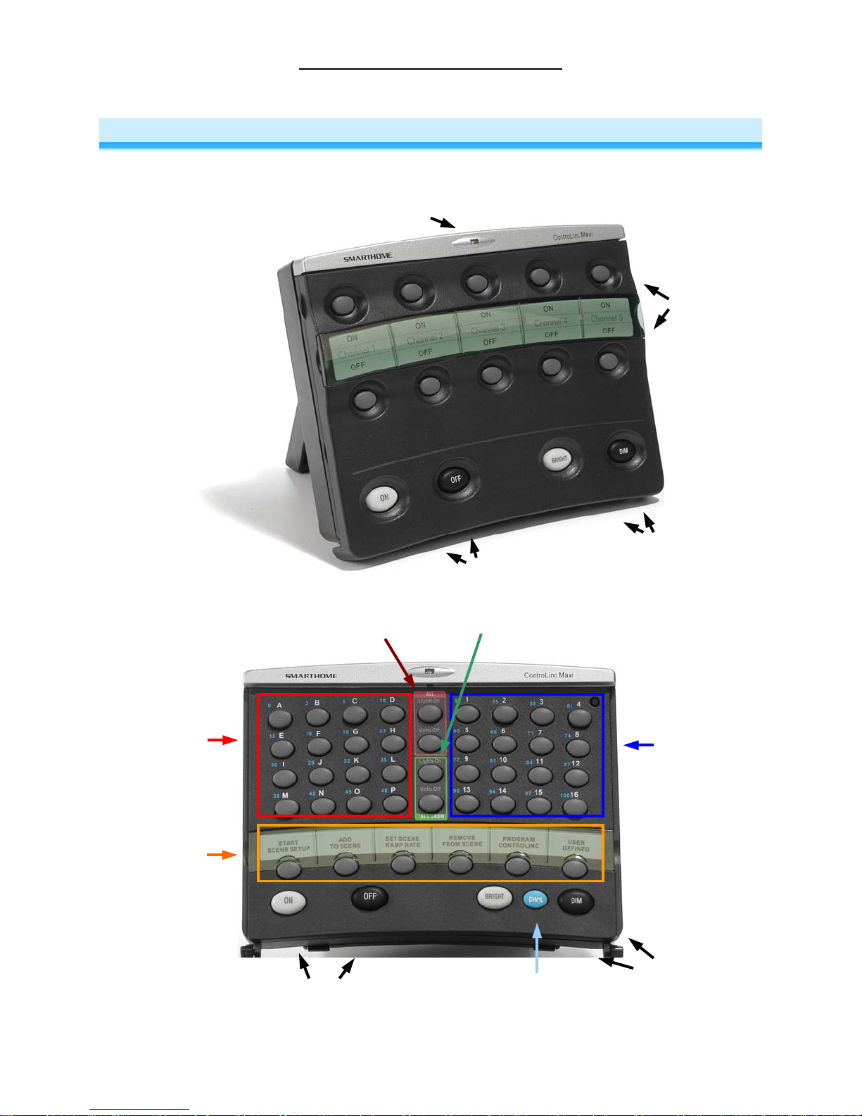
ABOUT CONTROLINC
Congratulations on purchasing the ControLinc™ Maxi Tabletop Controller. ControLinc allows you to
control both your legacy X10 products and all scene compatible Smarthome Design products.
Status LED
All On/Off
Buttons
ON/OFF Buttons
ll User On/Off
Buttons
User Defined
Buttons
BRIGHT/DIM
Buttons
House Code
Buttons
Pre Programmed
Buttons
ON/OFF
Buttons
Page 3 of 20
Preset Dim
Button
Unit Code
Buttons
BRIGHT/DIM
Buttons
Page 4

ControLinc™ Maxi™ User’s Guide
Key ControLinc Features
• Setup is easy – ControLinc installs in minutes
• Simple Guest-Friendly Soft-Touch On/Off Buttons
• Easily Access all 256 PLC Addresses
• Transmits Preset Dim Commands
• Programming Buttons for Smarthome Scene Compatible Products
• Flexible – User programmable buttons
• Multi House Code Programmable All Lights On/All Units Off Buttons
• Shows activity with Programmable status LED and Audible Sounder
• Stores setup state in memory, even while unplugged
• No Software, Special Programmer, or Intelligent Controller Required
• Multi-Angle Tabletop Stand Included
• Warranted for two years
Page 4 of 20
Page 5
ControLinc™ Maxi™ User’s Guide
HOW TO INSTALL CONTROLINC MAXI
Caution
Read and understand these instructions before installing, and retain them for future reference.
ControLinc is intended for installation in accordance with the National Electric Code and local regulations in the United
States, or the Canadian Electrical Code and local regulations in Canada. Use indoors only. ControLinc is not designed
nor approved for use on power lines other than 120V 60Hz, single phase. Attempting to use ControLinc on nonapproved powerlines may have hazardous consequences.
ControLinc Installation Tips
• Don’t plug ControLinc Maxi into an outlet controlled by a switch, because if the switch is inadvertently
turned off, ControLinc Maxi won’t have power.
• Don’t plug ControLinc Maxi into a filtered power strip or AC line filter.
Installing ControLinc Maxi
1. Plug ControLinc Maxi into an unswitched wall receptacle. The Status LED will illuminate steadily.
2. Begin using the ControLinc Maxi and/or programming User Defined Buttons.
Page 5 of 20
Page 6
ControLinc™ Maxi™ User’s Guide
BASIC OPERATION
Sending PLC Commands
When the cover is opened, buttons are provided for easy access to all 256 combinations of PLC House
and Unit codes. To control a receiver, follow these steps:
1. Press the House Code letter (Buttons A through P).
2. Press the Unit Code number (Buttons 1 through 16).
3. Press a command Button (On, Off, Dim, Bright, or Dim% and any blue Preset button).
Using Preset Dim Feature
Smarthome brand dimming-enabled products like SwitchLinc™, LampLinc™, KeypadLinc™, and
ToggleLinc™ are able to respond to PRESET dim commands. This command allows the user to precisely
set the modules brightness to one of 32 levels. To send a Preset Dim Commands, follow these steps:
1. Open the cover.
2. Press the House Code letter (Buttons A through P).
3. Press the Unit Code numbers (Buttons 1 through 16).
4. Press the blue Preset Dim button (“Dim%”) Once.
5. Press any any button with a blue label, which represents a preset level (example; Button K would
send a preset level of 32%).
Page 6 of 20
Page 7

ControLinc™ Maxi™ User’s Guide
USING PRE PROGRAMMED BUTTONS
The ControLinc Maxi includes four pre-programmed buttons that enable easy programming of sceneenabled Smarthome products. These buttons will send the unique “M-N-O-P” codes (i.e. “Clear
Sequence”) necessary to setup scenes. For more information on how to use scenes, see the “Scene
Address Programming” section in the manual’s for the products listed below.
The Following Smarthome X10/PLC products support scenes:
• SwitchLinc 2-Way and Plus Dimmers
• SwitchLinc RX Plus Dimmers
• SwitchLinc 2-Way Switches
• SwitchLinc Relay 2-Way
• SwitchLinc Timer Relay
• ToggleLinc 2-Way and Plus Dimmers
• ToggleLinc 2-Way Switches
• KeypadLinc Wall Mounted Controllers with Integrated Dimmer
• LampLinc 2-Way and Plus Dimmers
• ApplianceLinc 2-Way
The Following Smarthome INSTEON enabled products support scenes:
• LampLinc V2 Dimmer
• ApplianceLinc V2
• SwitchLinc V2 Dimmer
• SwitchLinc V2 On/Off Switch
• KeypadLinc V2
Using the Pre Programmed Buttons to Setup Scenes:
To create or add devices to a scene, follow these steps:
1. Open the cover.
2. Press the START SCENE SETUP button – This will send out the “Clear Sequence” (O16, N16, M16,
P16, M16).
3. Adjust the dimmer(s) to the desired On Level (Tip: Use the Preset Dim button to make setting up
scenes a snap!).
4. Press the ADD TO SCENE Button – This will send the “Lock-In Sequence” (M16, N16, O16, P16).
5. Press the House Code letter (Buttons A through P).
6. Press the Unit Code number (Buttons 1 through 16).
7. Most Smarthome module will confirm successful programming by blinking their loads.
Page 7 of 20
Page 8

ControLinc™ Maxi™ User’s Guide
Using the Pre Programmed Buttons to Setup Scenes Fade Rates:
To modify fade rates for devices in a scene, follow these steps:
1. Open the cover.
2. Press the ADD TO SCENE Button – This will send out the “Clear Sequence” (O16, N16, M16, P16,
M16).
3. Adjust the dimmer(s) to the desired Fade Rate (Tip: Use the Preset Dim button to make setting up
scenes a snap!).
4. Press the SET SCENE RAMP RATE Button – This will send the “Lock-In Sequence” (N16, O16, P16,
M16).
5. Press the House Code letter (Buttons A through P).
6. Press the Unit Code number (Buttons 1 through 16).
7. Most Smarthome module will confirm successful programming by blinking their loads.
Using the Pre Programmed Buttons to Delete Scenes:
To delete or remove devices from a scene, follow these steps:
1. Open the cover.
2. Press the ADD TO SCENE Button – This will send out the “Clear Sequence” (O16, N16, M16, P16,
M16).
3. Active the devices to be removed from the scene (example; To activate device “A16,” Press Buttons
A, 16, ON)
4. Press the REMOVE FROM SCENE Button – This will send the “Lock-In Sequence” (O16, P16, M16,
N16).
5. Press the House Code letter (Buttons A through P).
6. Press the Unit Code number (Buttons 1 through 16).
7. Most Smarthome module will confirm successful programming by blinking their loads.
Page 8 of 20
Page 9

ControLinc™ Maxi™ User’s Guide
ADVANCED CONTROLINC MAXI FEATURES
Overview of User Defined Buttons
The ControLinc Maxi has two distinct modes of operation; Cover Closed and Cover Open.
When the cover is closed, the unit has five user defined On/Off Button Pairs that allow the user to easily
turn on or off five different devices (X10/PLC Addresses) or scenes (See Programming Address es into a
Button Pairs). As an advanced feature, the button pairs can be split, allowing individual buttons to be
programmed independently (See Programming Individual Buttons)
Additionally the ControLinc Maxi offers user defined “All Lights On” and “All Units Off” buttons, which
allow the user to send a specific series of House Codes (See Programming All User Lights On and Units
Off Buttons below)
Programming All User Lights On and Units Off Buttons:
The two “All User” buttons allow the user to send All Lights On and All Units Off commands for a specific
series of House Codes. For example, if house codes “A,” “B,” and “F” are programmed to the All User
Buttons and the user presses the All User Lights On button; the ControLinc Maxi will send the following:
House Code A, All Lights On
House Code B, All Lights On
House Code F, All Lights On
To program the All User Lights On/Units Off Buttons, follow these steps:
1. Open the cover
2. Press and hold the “Program ControLinc” button for 3 seconds. The ControLinc Maxi sounder will
activate and the Status LED will begin to blink.
3. Press the All User Lights On Button
4. Press the House Code letter (Buttons A through P) for each House Code
5. Press the Program ControLinc button. The Status LED will stop blinking and illuminate steady.
Page 9 of 20
Page 10

ControLinc™ Maxi™ User’s Guide
Programming Addresses into a Button Pairs
When the cover is closed, the five On/Off Button pairs can be programmed to control any of the 256
different X10/PLC addresses. The default addresses are House Code A and Unit Codes 1 through 5.
When using the Button Pairs to control an address, the top buttons are used to send On commands and,
if held, bright commands. The bottom buttons are used to send Off commands and, if held, dim
commands.
To program Addresses into a Button Pair, follow these steps:
1. With the cover closed, press and hold the Dim and On buttons for 3 seconds, until the sounder is
heard. The Status LED will begin blinking.
2. Push the top button of the pair to be programmed.
3. Open the cover and press the House Code letter (Buttons A through P).
4. Press the Unit Code number (Buttons 1 through 16). The sounder will beep and the LED will stop
blinking, illuminating steady.
NOTE: If step 4 is not completed within 30 seconds, the ControLinc Maxi will beep and exit
programming mode.
Page 10 of 20
Page 11

ControLinc™ Maxi™ User’s Guide
Programming Individual Buttons
The 5 User Defined On/Off Button Pairs can be split and individually programmed to allow each of the 10
buttons to be programmed independently (not as pairs). This allows for easy control of up to 10 different
addresses. The individual buttons can be programmed to control an address or to send a string of X10
commands. Additionally the “USER DEFINED” Button (available when the cover is open) can be
programmed to send a string, or “sequence” of X10 commands giving the user 11 total programmable
buttons.
To program an individual button, follow these steps:
1. Open the cover
2. Press and hold the Program ControLinc button for 3 seconds. The ControLinc Maxi sounder will
activate and the Status LED will begin to blink.
3. Close the cover (or, if programming the User Sequence Button, press the User Sequence Button)
4. With the cover closed, press a user programmable button (any of the 10 On/Off Button Pairs)
5. Open the cover
6. Press a Unit Code Button (1 through 5) for the function to be programmed (see below):
Functions:
#1 – Toggle Mode for Appliances
When the button is pressed once, an On Command will be sent for the address programmed.
When pressed again, an Off command will be sent.
#2 – Toggle Mode for Lamps
Like Function 1; when the button is pressed once, an On Command will be sent for the
address programmed. When pressed again, an Off command will be sent. Pressing and
holding the button will send Bright or Dim commands until released.
#3 – Non-Toggle for Appliances
Always sends the same command (i.e. On or Off) for the programmed address
#4 – Non-Toggle for Lamps
Like Function #3; always sends the same command (i.e. On or Off) for the programmed
address. Pressing and holding the button will send Bright commands (if the On command is
programmed) or Dim commands (if the Off command is programmed).
#5 – X10 String/Sequence
Sends up to four X10 addresses and/or commands.
7. Enter the address and command:
Functions 1 and 2 Press a House Code (Buttons A through P)
Press a Unit Code (Buttons 1 through 16)
Functions 3 and 4 Press a House Code (Buttons A through P)
Press a Unit Code (Buttons 1 through 16)
Press the On or Off Button
Function 5 Enter up to four X10 Addresses (House Code and/or Unit Code) and/or
8. Press the Program ControLinc Button to complete programming. The sounder will beep and the LED
will stop blinking, illuminating steady.
commands (On, Off, Bright, Dim, All Lights On, All Units Off)
Page 11 of 20
Page 12

ControLinc™ Maxi™ User’s Guide
CONTROLINC MAXI FEATURES
Turning the Audible Sounder On and Off
The ControLinc Maxi offers the ability to enable or disable the audible sounder. The default setting for the
sounder is enabled. The ControLinc Maxi will emit a short beep whenever a button is pressed. If the
sounder is disabled, the ControLinc Maxi will only beep when in programming mode.
To enable or disable the audible sounder, follow these steps:
1. Open the cover
2. Press and hold the Program ControLinc button for 3 seconds. The ControLinc Maxi sounder will
activate and the Status LED will begin to blink.
3. Press the START SCENE SETUP Button
4. Press the Unit Code 1 Button. The sounder will beep and the LED will stop blinking, illuminating
steady.
NOTE: To re-enable the sounder (after disabling), repeats steps 1 through 4.
Turning the Status LED On and Off
The ControLinc Maxi offers the ability to enable or disable the Status LED. The default setting for the
Status LED is enabled. The Status LED will blink any time it is receiving or transmitting X10/PLC signals.
If the Status LED is disabled, it will only blink when in programming mode.
To enable or disable the Status LED, follow these steps:
1. Open the cover
2. Press and hold the Program ControLinc button for 3 seconds. The ControLinc Maxi sounder will
activate (if the sounder is enabled) and the Status LED will begin to blink.
3. Press the START SCENE SETUP Button
4. Press the Unit Code 2 Button to turn the Status LED ON. The sounder will beep and the LED will
stop blinking, illuminating steady.
or
5. Press the Unit Code 3 Button to turn the Status LED OFF. The sounder will beep and the LED will
stop blinking, illuminating steady.
Page 12 of 20
Page 13

ControLinc™ Maxi™ User’s Guide
Turning Polite Mode On and Off
The ControLinc Maxi offers the ability to enable or disable Polite Mode. The default setting for the Status
LED is enabled. Polite mode is an intelligent feature which, when enabled, will allow the ControLinc Maxi
to wait until the line is clear of other X10/PLC traffic before transmitting. This helps avoid signal collisions
with other controllers. If strong enough, the ControLinc Maxi may interpret electrical noise as traffic.
When using the ControLinc Maxi in extremely “noisy” conditions (electrically noisy that is), it’s best to
disable polite mode. If you’re not sure if you have a noisy electrical system, enable the Status LED (see
above for details) and notice the LED. If it blinks continuously, it’s a good indication of strong electrical
noise, and the Polite Feature should be disabled. Otherwise, leave this feature enabled.
To enable or disable the Polite Mode, follow these steps:
1. Open the cover
2. Press and hold the Program ControLinc button for 3 seconds. The ControLinc Maxi sounder will
activate (if the sounder is enabled) and the Status LED will begin to blink.
3. Press the START SCENE SETUP Button
4. Press the Unit Code 4 Button to turn the Polite Mode ON. The sounder will beep and the LED will
stop blinking, illuminating steady.
or
5. Press the Unit Code 5 Button to turn the Polite Mode OFF. The sounder will beep and the LED will
stop blinking, illuminating steady.
Factory Resetting the ControLinc Maxi
Performing a Factory Reset will erase all user programming. The ControLinc Maxi will reset to the
original factory settings. To perform a factory reset on the ControLinc Maxi, follow these steps:
1. Open the cover
2. Press and hold the Program ControLinc button for 3 seconds. The ControLinc Maxi sounder will
activate (if the sounder is enabled) and the Status LED will begin to blink.
3. Press the START SCENE SETUP Button
4. Press the Unit Code 16 Button to turn the Status LED ON. The sounder will beep and the LED will
stop blinking, illuminating steady.
If the ControLinc Maxi is locked up, the following steps will also perform a factory reset:
1. Unplug the ControLinc Maxi for 10 seconds
2. Press and hold the BRIGHT Button
3. While continuing to hold the BRIGHT button, plug in the ControLinc Maxi
4. Continue holding the BRIGHT Button for 3 seconds, until the ControLinc Maxi beeps.
Page 13 of 20
Page 14

ControLinc™ Maxi™ User’s Guide
HOW TO USE CONTROLINC MAXI
Using ControLinc Maxi’s Buttons
The following table gives an overview, and the sections thereafter give the details, on how to use ControLinc
Maxi’s buttons.
Button Applies To
Programmed as Button
ON
OFF
ON
OFF
BRIGHT
DIM
A - P
1 - 16
Programmed as Button
All Addresses Controlled
by All Button Pairs (or
Top 5 addresses when
All Addresses Controlled
by All Button Pairs (or
Top 5 addresses when
Last Button Pushed Open/Closed Brighten a Little
Last Button Pushed
Pairs
Pairs
split)
split)
House Code
Unit Code
Cover
Closed
Closed
Closed Ramp to On-Level N/A
Closed Ramp to OFF N/A
Open/Closed
Open
Open
Ramp to On-Level Brighten
Tap Press and Hold
Ramp to OFF Dim
Brighten Until
Dim a Little Dim Until Released
Transmits House
Code N/A
Transmits Unit
Code
Released
N/A
All Lights
On
All Units
Off
All User
Lights On
All User
Units Off
START
SCENE
SETUP
ADD TO
SCENE
DIM%
Last House Code Used
Last House Code Used
All User Programmed
House Codes
All User Programmed
House Codes
Any Smarthome Scene
Enabled Products
Any Smarthome Scene
Enabled Products
Any Devices that respond
to Preset Dim commands
Open
Open
Open
Open
Open Transmits “Clear
Open
Open
Page 14 of 20
Turns All Lights On N/A
Turns All Units Off N/A
Turns All Lights On N/A
Turns All Units Off N/A
Sequence” N/A
Transmits “Lock-In”
Sequence for
Scene Creation N/A
Activates (Blue)
Preset Dim Buttons
N/A
Page 15

ControLinc™ Maxi™ User’s Guide
Using the ON and OFF Button Pairs
The ON and OFF Buttons have a dual purpose. If you tap them briefly, they turn X10 Devices linked to the
address they control on or off. If you hold them down, the ON Button will brighten and the OFF Button will dim
any dimming modules linked to them. Holding down will not affect any non-dimmable (switchable) modules.
So, if you just want to turn things on or off, tap the appropriate button – don’t hold it down.
• To turn ON only those X10 Devices linked to an ON/OFF Button Pair, tap the ON Button of the Pair.
ControLinc Maxi will beep and its Status LED will blink off twice. Dimmable modules will go to whatever OnLevel they were set up for, at whatever Fade Rate they were set up for. Switchable modules will immediately
go full on.
• To turn OFF only those X10 Devices linked to an ON/OFF Button Pair, tap the OFF Button of the Pair.
ControLinc Maxi will beep and its Status LED will blink off twice. Dimmable modules will go full off at whatever
Fade Rate they were set up for. Switchable modules will immediately go full off.
• To brighten only those dimmable X10 Devices linked to an ON/OFF Button Pair, press and hold the ON
Button of the Pair. ControLinc Maxi will beep and its Status LED will blink off once. Dimmable modules will
begin to brighten, unless they are already fully bright. Switchable modules will not be affected. When you let
up, dimmable modules will stop going brighter and ControLinc Maxi’s Status LED will blink off again.
• To dim only those dimmable X10 Devices linked to an ON/OFF Button Pair, press and hold the OFF Button
of the Pair. ControLinc Maxi will beep and its Status LED will blink off once. Dimmable modules will begin to
dim, unless they are already fully off. Switchable modules will not be affected. When you let up, dimmable
modules will stop going dimmer and ControLinc Maxi’s Status LED will blink off again.
Using the ON and OFF Buttons (Lower Left, with Cover Closed)
The ON and OFF Buttons will turn on or turn off all X10 Devices linked to the addresses programmed to all 5 of
the On/Off Button Pairs. If the Button Pairs are split into individual buttons (See Programming Individual
Buttons), only the addresses programmed to the top 5 buttons will be controlled by the On/Off Buttons.
• To turn ON all and X10 Devices linked to the addresses programmed to all 5 of the On/Off Button Pairs, tap
the ON Button. ControLinc Maxi will beep and its Status LED will blink off once. Dimmable modules will go
to whatever On-Level they were set up for, at whatever Fade Rate they were set up for. Switchable modules
will immediately go full on.
• To turn OFF all INSTEON and Devices linked to the addresses programmed to all 5 of the On/Off Button
Pairs, tap the ALL OFF Button. ControLinc Maxi will beep and its Status LED will blink off once. Dimmable
modules will go full off at whatever Fade Rate they were set up for. Switchable modules will immediately go
full off.
Using the BRIGHT and DIM Buttons
The BRIGHT and DIM Buttons will brighten or dim only those X10 Devices linked to the last ON/OFF Button Pair
you used. Switchable modules will not be affected. Pressing and holding the BRIGHT and DIM Buttons will
adjust the brightness continuously, while tapping the buttons will adjust the brightness one of 32 steps for each
tap.
• To continuously brighten only those X10 Devices controlled by the last ON/OFF Button Pair you used, press
and hold the BRIGHT Button. ControLinc Maxi will beep and its Status LED will blink off once. Dimmable
modules will begin to brighten, unless they are already fully bright. Switchable modules will not be affected.
When you let up, dimmable modules will stop going brighter and ControLinc Maxi’s Status LED will blink off
again.
• To continuously dim only those X10 Devices controlled by the last ON/OFF Button Pair you used, press and
hold the DIM Button. ControLinc Maxi will beep and its Status LED will blink off once. Dimmable modules
Page 15 of 20
Page 16

ControLinc™ Maxi™ User’s Guide
will begin to dim, unless they are already fully off. Switchable modules will not be affected. When you let up,
dimmable modules will stop going dimmer and ControLinc Maxi’s Status LED will blink off again.
• To brighten by one step only those X1 0 Devices controlled by the last ON/OFF Button Pair you used, tap the
BRIGHT Button. ControLinc Maxi will beep and its Status LED will blink off once. Dimmable modules will
brighten one of 32 steps, unless they are already fully bright. Switchable modules will not be affected.
• To dim by one step only those X10 Devices controlled by the last ON/OFF Button Pair you used, tap the DIM
Button. ControLinc Maxi will beep and its Status LED will blink off once. Dimmable modules will dim one of
32 steps, unless they are already fully off. Switchable modules will not be affected.
Page 16 of 20
Page 17

ControLinc™ Maxi™ User’s Guide
MOUNTING OPTIONS FOR CONTROLINC MAXI
Tabletop Mounting
You can use ControLinc Maxi in a horizontal or a vertical position on the tabletop. To use in a vertical
position, pull out the hinged stand on the bottom of the unit.
Changing the Button Labels
The smoked plastic cover over the button labels will pop off by lifting from the sides. You can print new
labels using the templates available at
http://www.smarthome.com/files/2430-4071_Label_Print.zip.
Page 17 of 20
Page 18

TROUBLESHOOTING
Problem Possible Cause Solution
The Status LED on my
ControLinc Maxi is not
turning on at all.
My ControLinc Maxi is
not controlling X10
devices.
A device is not
responding to ControLinc
Maxi.
ControLinc Maxi is
locked up.
ControLinc Maxi is not getting
power.
ControLinc Maxi and your
device(s) are on opposite
powerline phases.
ControLinc Maxi is plugged
into a power strip.
Other modules are loading
down the signal.
The signal may be too weak.
A surge or excessive noise
on the powerline may have
glitched it.
ControLinc™ Maxi™ User’s Guide
Make sure ControLinc Maxi is not plugged into a
switched outlet that is turned off.
Make sure to have a coupler-repeater properly installed
to bridge the two powerline phases.
Powerline signals can’t travel through power filters.
Plugging ControLinc Maxi directly into a wall outlet
works best.
Other transmitting products can absorb the
ControLinc Maxi’s signal. Moving it to another
outlet or electrically away from other transmitters
will help..
Add a BoosterLinc enabled device or move around
existing BoosterLincs devices.
Try controlling your device with the ControLinc Maxi
plugged into the same outlet.
Unplug ControLinc Maxi for 10 seconds and reinstall.
If the above doesn’t work, perform a Factory Reset.
Reset the entire ControLinc Maxi by performing a
Factory Reset.
The Status LED on my
ControLinc Maxi doesn’t
work.
The beeper on my
ControLinc Maxi doesn’t
work.
All of my X10 Devices do
not respond to
ControLinc Maxi’s All
Lights ON or All Units
OFF Buttons.
All of my INSTEON or
X10 Devices do not
respond to ControLinc
Maxi’s BRIGHT or DIM
Buttons.
ControLinc Maxi’s plug
does not fit in my wall
outlet.
The Status LED may have
been turned off.
The beeper may have been
turned off.
The ALL ON and ALL OFF
Buttons only control the last
House Code.
The BRIGHT and DIM
Buttons only control X10
devices controlled by the last
ON/OFF Button Pair you
pushed on ControLinc Maxi.
The polarized prongs on the
plug are not compatible with
older AC outlets.
Enable the Status LED.
Enable the Sounder
Select the appropriate House Code before sending the
All Lights On or All Units Off command
Push the ON or OFF Button for the Button Pair (X10
Address) you want to control, then use the BRIGHT and
DIM Buttons.
ControLinc Maxi’s plug is polarized so that it may only
be inserted one way into a receptacle. If your home’s
outlets are over 40 years old, replacing the outlet with a
modern one will allow ControLinc Maxi and many other
modern devices to be used safely. DO NOT defeat this
safety feature.
If you have tried these solutions, reviewed this User’s Guide, and still cannot resolve an issue, please:
• Search our online knowledge base at http://smarthome.custhelp.com
.
• Call our Support Department at 800-SMARTHOME (800-762-7846).
• Email us at
tech@smarthome.com.
Page 18 of 20
Page 19

ControLinc™ Maxi™ User’s Guide
SPECIFICATIONS
ControLinc Maxi’s Specifications
General
Smarthome Product Number 4071, ControLinc Maxi Tabletop Controller
Warranty 2 years
Operation
ON/OFF Button Pairs 5 Channels or 10 Buttons
ALL ON/ALL OFF Buttons Control all X10 devices linked to Channels 1-5 (Or Top 5 Buttons)
BRIGHT/DIM Buttons Control X10 devices linked to last pressed Channel
Audio Alert Beeper, can be disabled
Status LED Green, can be disabled
Button Modes House Code (HC) Only, Unit Code (UC) Only, HC+UC, HC+UC+Command
Combo Mode Message Order Toggle and Non-toggle, Address Only, Command Only, Address and Command
Setup Memory Non-volatile EEPROM
X10 Features
X10 Addresses All of the 256 possible
X10 Status Response Supported
X10 Powerline Frequency 121 kHz
X10 Minimum Transmit Level 3.2 Vpp into 5 Ohms
X10 Minimum Receive Level 10 mVpp nominal
X10 Messages Repeated No
Mechanical
Mounting Included desk stand (flat or vertical)
Button Labels Printable using template
Operating Conditions Indoors, 32 to 122°F, up to 85% relative humidity
Dimensions 5.0” H x 6.4” W x 3.0” D
Weight 1 lb 5 oz
Electrical
Supply Voltage 120 Volts AC +/- 10%, 60 Hertz, single phase
Surge Protection MOV rated for 150 Volts
Power Cord 6 ft, 2-pin polarized plug
Certification Safety tested for use in USA and Canada (ETL #3017581)
Page 19 of 20
Page 20

ControLinc™ Maxi™ User’s Guide
Certification
ControLinc Maxi has been thoroughly tested by ITS ETL SEMKO, a nationally
recognized independent third-party testing laboratory. The North American ETL Listed
mark signifies that the product has been tested to and has met the requirements of a
widely recognized consensus of U.S and Canadian product safety standards, that the
manufacturing site has been audited, and that the manufacturer has agreed to a
program of quarterly factory follow-up inspections to verify continued conformance.
Limited Warranty
Seller warrants to the original consumer purchaser of this product that, for a period of two years from the
date of purchase, this product will be free from defects in material and workmanship and will perform in
substantial conformity to the description of the product in this User’s Guide. This warranty shall not apply
to defects or errors caused by misuse or neglect. If the product is found to be defective in material or
workmanship, or if the product does not perform as warranted above during the warranty period, Seller
will either repair it, replace it or refund the purchase price, at its option, upon receipt of the product at the
address below, postage prepaid, with proof of the date of purchase and an explanation of the defect or
error. The repair, replacement, or refund that is provided for above shall be the full extent of Seller’s
liability with respect to this product. For repair or replacement during the warranty period, call Smarthome
customer service to receive an RA# (return authorization number), properly package the product (with the
RA# clearly printed on the outside of the package) and send the product, along with all other required
materials, to:
Smarthome, Inc.
ATTN: Receiving Dept.
16542 Millikan Ave.
Irvine, CA 92606-5027
Limitations
The above warranty is in lieu of and seller disclaims all other warranties, whether oral or written, express
or implied, including and warranty or merchantability or fitness for a particular purpose. Any implied
warranty, including any warranty of merchantability or fitness for a particular purpose, which may not be
disclaimed or supplanted as provided above shall be limited to the one-year period of the express
warranty above. No other representation or claim of any nature by any person shall be binding upon
seller or modify the terms of the above warranty and disclaimer. In no event shall seller be liable for
special, incidental, consequential, or other damages resulting from the possession or use of this product,
including without limitation damage to property and, to the extent permitted by law, personal injury, even if
seller knew or should have known of the possibility of such damages. Some states do not allow
limitations on how long an implied warranty lasts and/or the exclusion or limitation of damages, in which
case the above limitations and/or exclusions may not apply to you. You may also have other legal rights
that may vary from state to state.
INSTEON, Plug-n-Tap, ControLinc, TesterLinc, SignaLinc, LampLinc, ToggleLinc, BoosterLinc, ApplianceLinc, KeypadLinc,
FilterLinc, ProbeLinc, SwitchLinc, TempLinc, IR Linc and SmarthomeLive are trademarks of Smarthome, Inc. INSTEON
networking technology is covered by pending U.S. and foreign patents.
© Copyright 2005 Smarthome, Inc., 16542 Millikan Ave., Irvine, CA 92606-5027,
800-SMARTHOME (800-762-7846), 949-221-9200,
www.smarthome.com
Rev 050706
Page 20 of 20
 Loading...