


 Loading...
INSTEON™KeypadLinc™
V2 Dimmer
INSTEON Keypad Dimmer
For models:
#2486D KeypadLinc V2 Dimmer

INSTEON KeypadLinc V2 Dimmer User’s Guide
TABLE OF CONTENTS |
|
ABOUT INSTEON KEYPADLINC DIMMER ................................................................................................ |
4 |
What is INSTEON?.................................................................................................................................... |
4 |
Key KeypadLinc Dimmer Features............................................................................................................ |
4 |
HOW TO INSTALL KEYPADLINC DIMMER ............................................................................................... |
5 |
Typical Tools You Will Need ..................................................................................................................... |
5 |
Preparing to Install KeypadLinc Dimmer ................................................................................................... |
6 |
Attach Six Button or Eight Button Plate..................................................................................................... |
7 |
Button Nomenclature................................................................................................................................. |
7 |
Installing KeypadLinc Dimmer in a Multi-Way Circuit................................................................................ |
9 |
Configure For Six or Eight Button Operation........................................................................................... |
15 |
HOW TO SET UP KEYPADLINC DIMMER TO REMOTELY CONTROL AN INSTEON DEVICE ........... |
16 |
Linking KeypadLinc Dimmer to a Controlled INSTEON Device .............................................................. |
16 |
Unlinking a Controlled INSTEON Device from KeypadLinc Dimmer ...................................................... |
17 |
Creating an INSTEON Scene.................................................................................................................. |
17 |
HOW TO SET UP KEYPADLINC DIMMER TO BE REMOTELY CONTROLLED BY AN INSTEON |
|
CONTROLLER ........................................................................................................................................... |
18 |
Linking an INSTEON Controller to KeypadLinc Dimmer......................................................................... |
18 |
Unlinking KeypadLinc Dimmer from an INSTEON Controller ................................................................. |
18 |
Unlinking KeypadLinc Dimmer from an INSTEON Controller ................................................................. |
19 |
HOW TO SET UP ON-LEVELS AND RAMP RATES................................................................................ |
20 |
Setting the On-Level................................................................................................................................ |
20 |
Setting the On-Level and Ramp Rates (Optional)................................................................................... |
20 |
Setting the Ramp Rate ............................................................................................................................ |
21 |
Locking In a Remote-Controlled On-Level and Ramp Rate.................................................................... |
21 |
Locking In a Local On-Level and Ramp Rate.......................................................................................... |
21 |
HOW TO CROSS-LINK MORE THAN ONE KEYPADLINC DIMMER...................................................... |
22 |
Cross-Linking in a 3-Way Circuit ............................................................................................................. |
22 |
ADVANCED FEATURES OF KEYPADLINC DIMMER ............................................................................. |
23 |
Restoring Power to KeypadLinc Dimmer ................................................................................................ |
23 |
Resetting KeypadLinc Dimmer to Its Factory Default Settings ............................................................... |
23 |
Toggle Mode............................................................................................................................................ |
23 |
Grouping Buttons..................................................................................................................................... |
24 |
Variable Backlight Brightness.................................................................................................................. |
24 |
X10 PROGRAMMING OPTIONS ............................................................................................................... |
25 |
Setting the X10 Primary Address ............................................................................................................ |
25 |
Removing the X10 Primary Address ....................................................................................................... |
25 |
Setting the X10 On-Level and X10 Ramp Rate for the X10 Primary Address ........................................ |
26 |
Enabling and Disabling Resume Dim...................................................................................................... |
26 |
ADVANCED X10 PROGRAMMING OPTIONS.......................................................................................... |
27 |
Remotely Setting the On-Level for the X10 Primary Address................................................................. |
27 |
Remotely Setting the Ramp Rate for the X10 Primary Address ............................................................. |
27 |
About X10 Scene Address Programming................................................................................................ |
28 |
Remotely Setting an X10 Scene Address and On-Level ........................................................................ |
28 |
Remotely Removing an X10 Scene Address .......................................................................................... |
28 |
Remotely Setting the Ramp Rate for an X10 Scene Address................................................................. |
29 |
HOW TO USE KEYPADLINC DIMMER..................................................................................................... |
30 |
Using the Buttons .................................................................................................................................... |
30 |
Using the Air Gap .................................................................................................................................... |
30 |
Custom Keypad Labels ............................................................................................................................ |
31 |
Use enclosed pre-printed button labels or make your own ..................................................................... |
31 |
ABOUT INSTEON ...................................................................................................................................... |
32 |
Understanding Why an INSTEON Network Is Reliable........................................................................... |
32 |
Further Enhancing Reliability .................................................................................................................. |
32 |
Using Smarthome’s SignaLinc RF to Upgrade Your INSTEON Network ............................................... |
32 |
About INSTEON and X10........................................................................................................................ |
33 |
TROUBLESHOOTING................................................................................................................................ |
34 |
SPECIFICATIONS ...................................................................................................................................... |
36 |
KeypadLinc Dimmer Specifications......................................................................................................... |
36 |
Certification.............................................................................................................................................. |
38 |
Limited Warranty ..................................................................................................................................... |
38 |
INSTEON KeypadLinc V2 Dimmer User’s Guide
ABOUT INSTEON KEYPADLINC DIMMER
Congratulations on purchasing the INSTEON™ KeypadLinc™ Dimmer. With its elegant look, smooth touch, and convenient secondary buttons, you can not only control the lights that you wire it to, but you can remotely control all kinds of other INSTEON and X10 devices in your home to match your lifestyle, all from the same switch. Besides controlling other devices, KeypadLinc Dimmer can itself be remotely operated from other INSTEON or X10 Controllers, including other KeypadLinc Dimmers.
What is INSTEON?
INSTEON is a simple, reliable, and affordable breakthrough in home control. Simple, because Plug-n- Tap™ setup is a breeze, and there are no wires to add – INSTEON uses existing powerline wiring as well as radio-frequency for communication. Reliable, because every INSTEON device is a two-way repeater. And affordable, not just because of low cost, but because INSTEON also works with legacy X10 devices. An INSTEON home grows in value with every INSTEON device you add, making life more convenient, safe and fun.
Key KeypadLinc Dimmer Features
•After installation, setup is easy – links to controlled devices and other controllers in minutes
•Controls all standard incandescent lamps, up to a total load of 600 watts
•Dedicated load controlling buttons, and two included button plates that provide a choice of four or seven secondary buttons.
•Changes brightness at 32 ramp rates
•Includes label inserts for commonly used functions, and templates for printing customized label inserts.
•Responds to commands from X10 controllers and sends X10 commands to X10 devices
•Wires in like a standard wall switch (but also requires a NEUTRAL connection)
•Supports “virtual” 3-, 4-, or more-way circuits with multiple KeypadLinc Dimmers
•Includes white and ivory frames for matching to common trim plates
•Capable of operating in X10 or Insteon mode only, or hybrid mode which sends/receives both X10 and Insteon signals
•Warranted for two years
Page 4 of 38

INSTEON KeypadLinc V2 Dimmer User’s Guide
HOW TO INSTALL KEYPADLINC DIMMER
Caution
Read and understand these instructions before installing, and retain them for future reference.
KeypadLinc Dimmer is intended for installation in accordance with the National Electric Code and local regulations in the United States, or the Canadian Electrical Code and local regulations in Canada. Use indoors only. KeypadLinc Dimmer is not designed nor approved for use on power lines other than 120V 60Hz, single phase. Attempting to use KeypadLinc Dimmer on non-approved powerlines may have hazardous consequences.
Do not install KeypadLinc Dimmer to control a receptacle or fluorescent lighting fixture. Connect only copper or copperclad wire to KeypadLinc Dimmer. Before installing, disconnect power at the circuit breaker or remove the circuit’s fuse to avoid shock or possible damage to KeypadLinc Dimmer. It is recommended that a qualified electrician perform this installation.
To reduce the risk of overheating and possible damage to other equipment, use KeypadLinc Dimmer to control 110V incandescent lamps only. Dimming an inductive load, such as a fan or transformer, could cause damage to the dimmer, the load device, or both. If the manufacturer of the load device does not recommend dimming, use a non-dimming INSTEON switch such as SwitchLinc V2 Relay. USER ASSUMES ALL RISKS ASSOCIATED WITH DIMMING AN INDUCTIVE LOAD.
Proper installation of at least two SignaLinc™ RF Signal Enhancers is required prior to installing and using other INSTEON devices.
Typical Tools You Will Need
•A flat screwdriver to remove the faceplate from the switch junction box.
•A Phillips screwdriver for the screws that hold KeypadLinc Dimmer in the junction box.
•A wire cutter and stripper if the switch you are replacing requires you to cut the wires to remove them.
•A small Phillips screwdriver if you will be changing the color of the trim frame and paddle.
A Helpful Tool – Voltmeter or Voltage Tester
During the installation of KeypadLinc Dimmer, it may be necessary to identify the wires inside the junction box. Knowing for sure which wire is the LINE (sometimes called HOT) can reduce the guesswork when installing a single switch, and it is absolutely necessary when working with multi-way lighting circuits. A voltmeter is ideal for this application. Many of the digital models can also read current so you can measure how much power is being drawn by the switch’s load.
A simpler measurement tool, available at most home improvement centers, is a voltage sensor. This device, often costing less than $20, can sense voltage when placed near a wire. The tip of the voltage sensor can tell if voltage is on the wire without touching the bare copper conductor or breaking the insulation.
When using these tools, be certain to read and understand the safety instructions. Often when these tools are used, the power to the circuit will need to be turned on. When working around live electrical wires, take your time and concentrate on the task.
Page 5 of 38

INSTEON KeypadLinc V2 Dimmer User’s Guide
Preparing to Install KeypadLinc Dimmer
IMPORTANT!
If you are not knowledgeable about and comfortable with electrical circuitry, you should have a qualified electrician install KeypadLinc Dimmer for you. If you have any questions, please consult an electrician or call
Smarthome Tech Support
800-SMARTHOME
(800-762-7846)
Prior to installing KeypadLinc Dimmer, please review the entire installation procedure, and take the following precautions:
•Be sure that you have turned off the circuit breaker or removed the fuse for the circuit you are installing KeypadLinc Dimmer in. Installing KeypadLinc Dimmer with the power on will expose you to dangerous voltages.
•KeypadLinc Dimmer requires a small amount of power to operate, which it receives from a connection to the NEUTRAL electrical wire (usually white). If you are replacing a standard mechanical switch with KeypadLinc Dimmer, the switch you are replacing will normally not have a connection to the neutral wire. However, most junction boxes will contain a NEUTRAL wire that you can connect KeypadLinc Dimmer to. If your junction box does not contain a neutral wire, please call SmartHome Tech Support at 800-SMARTHOME (800-762-7846), or consult an electrician.
•Don’t use KeypadLinc Dimmer to control low-voltage lighting, fluorescent lights, or motors. These are inductive loads, which KeypadLinc Dimmer is not designed to control. Use a Smarthome SwitchLinc V2 Relay instead.
•Don’t use KeypadLinc Dimmer to control an electrical outlet, because non-dimmable or inductive loads may be plugged into it.
•KeypadLinc Dimmer may feel warm during operation. The amount of heat generated is within approved limits and poses no hazards. To minimize heat buildup, ensure that the area surrounding the rear of KeypadLinc Dimmer has adequate ventilation by clearing away excess insulation.
Page 6 of 38
INSTEON KeypadLinc V2 Dimmer User’s Guide
Attach Six Button or Eight Button Plate
Each KeypadLinc V2 Dimmer is packaged with a six key and an eight key button plate.
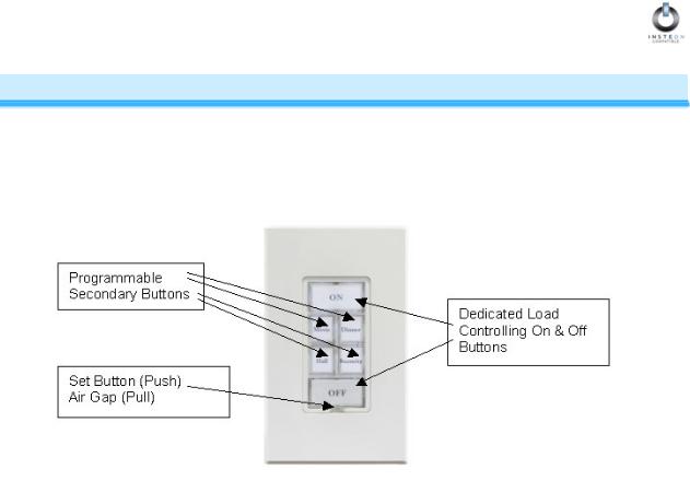
•The six key button plate provides a dedicated load ON button at the top of the switch, a dedicated load OFF button at the bottom, and four programmable secondary keys between the ON and OFF buttons.
•The eight key button plate provides a dedicated load ON/OFF button in the top left-most position of the switch, and seven programmable
secondary buttons.
Attach the desired plate to the switch body by aligning the plastic tabs and snap into place. Proceed with the physical installation of KeypadLinc Dimmer.
NOTE
Note: For proper operation, KeypadLinc Dimmer must be programmed to operate in six key or eight key mode, corresponding to whichever plate is attached. Factory default is six key mode. Please see section titled “Configure For Six or Eight Button Operation” for instructions.
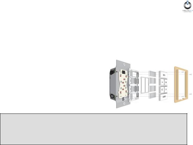
Button Nomenclature
Since KeypadLinc Dimmer has removable button labels, it can become confusing when trying to refer to a specific button of the six available (or eight buttons when the eight button key plate is installed). Refer to the following diagrams for button “names”.
|
|
|
|
|
|
|
|
|
|
|
|
|
|
|
|
|
|
|
|
|
|
|
ON |
|
|
|
|
|
|
A |
|
|
B |
|
|
||
|
|
|
|
|
|
|
|
|
|
|
|
|
|
|
|
|
|
|
|
|
|
|
|
|
|
|
|
|
|
|
|
|
|
|
|
|
|
|
|
|
|
|
|
|
|
|
|
|
|
|
|
|
|
|
|
|
|
|
A |
|
|
B |
|
|
|
|
|
C |
|
|
D |
|
|
||
|
|
|
|
|
|
|
|
|
|
|
|
|
|
|
|
|
|
|
|
|
|
|
|
|
|
|
|
|
|
|
|
|
|
|
|
|
|
|
|
|
|
|
|
|
|
|
|
|
|
|
|
|
|
|
||
|
|
C |
|
|
D |
|
|
|
|
|
E |
|
|
F |
|
|
||
|
|
|
|
|
|
|
|
|
|
|
|
|
|
|
|
|
|
|
|
|
|
|
|
|
|
|
|
|
|
|
|
|
|
|
|
|
|
|
|
|
|
|
|
|
|
|
|
|
|
|
|
|
|
|
|
|
|
|
|
|
OFF |
|
|
|
|
|
|
|
|
|
|
|
|
||
|
|
|
|
|
|
|
|
|
|
G |
|
|
H |
|
|
|||
|
|
|
|
|
|
|
|
|
|
|
|
|
|
|
|
|
||
|
|
|
|
|
|
|
|
|
|
|
|
|
|
|
|
|
|
|
|
|
|
|
|
|
|
|
|
|
|
|
|
|
|
|
|
|
|
|
|
|
|
|
|
|
|
|
|
|||||||||
|
|
SIX BUTTON |
|
|
|
|
|
EIGHT BUTTON |
|
|||||||||
|
|
|
|
|
|
|
|
|
Page 7 of 38 |
|
|
|
|
|||||
INSTEON KeypadLinc V2 Dimmer User’s Guide
Installing KeypadLinc Dimmer
1.For best INSTEON Network performance, be sure you have properly installed at least two SignaLinc RF Signal Enhancers.
2.At the circuit breaker or fuse panel, disconnect the power for all of the circuits in the switch junction box. Verify that power is off by trying to turn on the lights controlled by the switches.
3.Remove the faceplate from the switch junction box, then unscrew the switch you are replacing and pull it out from the junction box.
4.Disconnect the wires from the switch you are replacing. If the wires cannot be detached by unscrewing them, cut the wires where they enter the switch, then strip ½” of insulation off the ends.
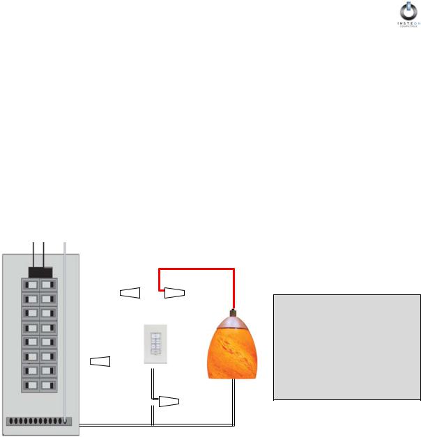
5.If you are installing KeypadLinc Dimmer into a standard two-way circuit (where only one switch controls the load), follow the diagram below to identify and connect the LINE, LOAD, NEUTRAL, and GROUND wires. If the colors of the wires do not match the diagram, be sure you have identified the wires correctly before connecting them.
6.If you are installing KeypadLinc Dimmer into a multi-way circuit (where more than one switch controls the same load), follow the instructions in the section titled Installing KeypadLinc Dimmer in a Multi-Way Circuit to identify and connect the LINE, TRAVELER, NEUTRAL, and GROUND wires.
LINE |
LOAD |
|
Usually Black |
Usually Red, Blue or Black |
|
|
|
|
|
|
|
|
|
|
|
|
|
|
|
|
|
|
LINE |
|
|
LOAD |
||
|
|
|
|
Black |
|
|
Red |
||
|
|
GROUND |
|
|
|
||||
|
|
Bare Copper |
|
|
Light |
||||
|
|
|
|
|
|
|
|
|
|
|
|
|
|
|
|
|
|
|
Fixture(s) |
|
|
|
|
|
|
|
|
||
|
|
|
|
|
|
|
|
NEUTRAL |
|
|
|
GROUND |
|
White |
|||||
|
|
Bare Copper |
|
|
|
||||
|
|
|
|
|
|
|
|
|
|
|
|
|
|
|
|
|
|
|
|
|
|
|
|
NEUTRAL |
|||||
Main Panel |
|
|
Usually White |
||||||
NOTE
The NEUTRAL wire will not normally be connected to the switch you are replacing. If there is no NEUTRAL wire in the junction box, please consult an electrician or call
SmartHome Tech Support
800-SMARTHOME
120VAC
7.After you have connected all of the wires, ensure that all of the wire connectors are firmly attached and that there is no exposed copper except for the GROUND wire.
8.Orient KeypadLinc Dimmer with the SET button on bottom, gently place it into the junction box, then screw it into place.
9.Turn the circuit breaker back on or re-install the fuse.
10.After the SET button illuminates, verify KeypadLinc Dimmer is working properly by turning the light on and off.
11.Reinstall the trim plate.
Page 8 of 38

INSTEON KeypadLinc V2 Dimmer User’s Guide
Installing KeypadLinc Dimmer in a Multi-Way Circuit
Understanding Multi-Way Circuits
If more than one switch controls a single set of lights (called a LOAD), the switches are part of a multi-way circuit. A 3-way circuit uses two switches to control a LOAD, a 4-way circuit uses three switches, and so forth. Most homes have one or more 3-way circuits, with two switches located in hallways, stairwells, or two different entrances to a room. Less commonly found are circuits that are 4-way or above.
You can use KeypadLinc Dimmers to replace switches in existing multi-way circuits, or you can use them to create virtual multi-way circuits without the need to run additional wiring.
Here is how a wired-in three-way circuit (with two switches) works:
A wired-in fouror more-way circuit (with three or more switches) has additional switches added in the middle of the circuit. In the diagram below, the additional switch is shown in one position in the upper box and in the other position below.
To learn more about multi-way circuits, go to Google.com or another search engine on the Internet and enter the search terms “three-way switch” or “four-way switch.”
Page 9 of 38
INSTEON KeypadLinc V2 Dimmer User’s Guide
Using KeypadLinc Dimmers in Virtual Multi-Way Circuits
In a virtual multi-way circuit, only one KeypadLinc Dimmer, called the KeypadLinc Primary, actually controls the LOAD in the multi-way circuit. Any additional KeypadLinc Dimmers, called KeypadLinc Secondaries, are not connected to the LOAD, but only to the powerline (via the LINE and NEUTRAL). All of the KeypadLinc Dimmers can communicate with one another using INSTEON networking on the powerline. After wiring in the KeypadLinc Dimmers, you create the virtual multi-way circuit by setting up all of the KeypadLinc Dimmers to control each other (see HOW TO SET UP KEYPADLINC DIMMER TO REMOTELY CONTROL AN INSTEON DEVICE, below).
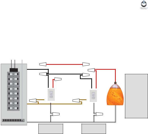
The diagram below shows how you convert a wired-in three-way circuit into a virtual three-way circuit using two KeypadLinc Dimmers. Step-by-step instructions for wiring in the KeypadLinc Dimmers are in the next section.
|
|
TRAVELER 1 |
|
|
|
|
LINE |
Red* or Blue* |
|
LOAD |
|
|
|
|
|
||
|
Black* |
TRAVELER 2 |
|
Red* or Blue* |
|
|
|
|
|
||
|
|
Black* |
|
|
|
|
LINE |
LOAD |
|
LINE |
LOAD |
|
Black |
Red |
|
Black |
Red |
|
GROUND |
|
GROUND |
Light |
|
|
Bare Copper |
|
Bare Copper |
||
|
|
Fixture(s) |
|||
|
|
|
|
|
|
|
GROUND |
NEUTRAL |
|
|
NEUTRAL |
|
Bare Copper |
|
|
||
|
White |
|
|
White |
|
|
|
|
|
||
|
KeypadLinc |
NEUTRAL |
KeypadLinc |
||
Main Panel |
White* |
||||
120 VAC |
Secondary |
|
Primary |
||
NOTE
Wire colors marked with a * are the usual colors and may differ in some homes.
Notice that one of the TRAVELER wires (number 1, the red one) is not used, so you will cap it off at both ends with a wire nut.
The other TRAVELER (number 2, the black one) you will convert to a LINE wire. In the junction box where the KeypadLinc Secondary is, connect TRAVELER 2 to the existing LINE and also to the KeypadLinc Secondary’s LINE wire. In the other junction box at the other end, you will connect TRAVELER 2 to the KeypadLinc Primary’s LINE wire.
The KeypadLinc Primary’s LOAD wire gets connected to the actual lights that are being controlled.
The LOAD wire for any KeypadLinc Secondaries that you will be installing will not be connected to anything, so cap those LOAD wires off with a wire nut.
All KeypadLinc Dimmers, whether they are Primaries or Secondaries, must be connected to NEUTRAL and to GROUND. Note that the switches you are replacing will not normally have a connection to NEUTRAL. If there is no NEUTRAL wire in the junction box, please consult an electrician or call SmartHome Tech Support, 800-SMARTHOME (800-762-7846).
Page 10 of 38
INSTEON KeypadLinc V2 Dimmer User’s Guide
Step-by-Step Instructions for Installing Multi-Way KeypadLinc Dimmers
When replacing a three-way mechanical switch, each switch will have three wires connected to it from the wall box. Four-way or greater circuits will have four wires connected to the switches in the center of the circuit. For this tutorial, we will follow the most commonly used wire colors for homes in North America.
1.Find the LINE wire. Your first task is to find out which switch junction box is the one where the electricity comes into the circuit. This box will contain the LINE wire (sometimes called HOT).
a.Turn off the electricity at the circuit breaker panel.
b.Pull all the switches in the multi-way circuit out of their junction boxes. Each switch should have three wires connected to it. If the circuit is a four-way or greater, some of the switches will have four wires.
c.Disconnect the wires from the old switches. If the wires cannot be detached by unscrewing them, cut the wires where they enter the switch, then strip ½ inch of insulation off the ends.
d.Making sure that none of the wires are touching anything and that no one is around the wall boxes, turn the electricity back on.
e.Using a voltmeter or voltage sensor, individually test each wire for voltage. When you measure 120 Volts AC, that wire is the LINE wire. LINE wires are usually black.
f.The other two wires, usually black and red, are the TRAVELERS and go to the next junction box. TRAVELER wires are usually in the same cable sheath.
g.Turn off the electricity to resume installing the new KeypadLinc Dimmers.
2.Connect the KeypadLinc Secondary’s LINE Wire. The KeypadLinc Dimmer that will be the Secondary goes in the junction box where you found the LINE wire. Connect the black LINE wire that you found, the black TRAVELER, and the Black LINE wire on KeypadLinc Dimmer all together with a single wire nut. If another type of Insteon or X10 device is to be installed as the secondary switch, installation is likely as described above, but you should verify the installation instructions specific to that device.
Page 11 of 38
INSTEON KeypadLinc V2 Dimmer User’s Guide
3.Cap the other TRAVELER house wire. The other TRAVELER wire, usually red, will not be used, so put a wire nut on the end of it.
4.Cap the red LOAD wire from the KeypadLinc Secondary.
Put a wire nut on the end of the KeypadLinc Secondary’s LOAD wire to ensure that it won’t connect to anything.
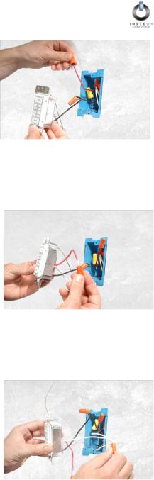
5.Connect the KeypadLinc Secondary’s NEUTRAL Wire.
Locate the group of NEUTRAL wires, usually white, in the rear of the box. The old switch should not have been connected to the NEUTRAL wires, but KeypadLinc Dimmer requires this connection in order to draw a small amount of power for itself. Connect KeypadLinc Secondary’s white NEUTRAL wire to the other NEUTRAL wires with a wire nut.
Page 12 of 38
Loading...