

Page 1
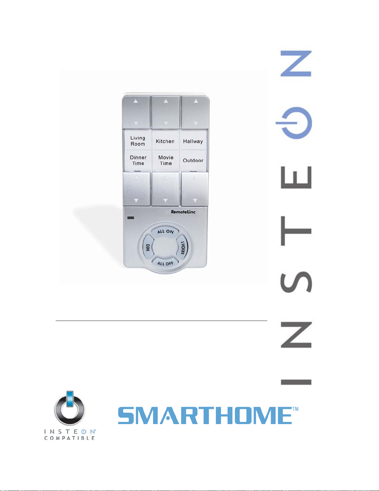
RemoteLinc
Model : 2440
INSTEON® Wireless Remote Control
Page 2

RemoteLinc Owner’s Manual
TABLE OF CONTENTS
ABOUT REMOTELINC ................................................................................................................................. 3
Key RemoteLinc Features ......................................................................................................................... 3
What is Included with RemoteLinc ............................................................................................................ 3
WHAT IS INSTEON? .................................................................................................................................... 4
INSTALLATION ............................................................................................................................................ 4
Installing RemoteLinc ................................................................................................................................ 4
USING REMOTELINC .................................................................................................................................. 5
Using the RemoteLinc Buttons .................................................................................................................. 5
Creating a Custom RemoteLinc Label ...................................................................................................... 5
CONTROLLING INSTEON RESPONDERS FROM SWITCHLINC DIMMER ............................................. 6
Linking RemoteLinc to an INSTEON Responder ...................................................................................... 6
Unlinking an INSTEON Responder from RemoteLinc .............................................................................. 6
CREATING AN INSTEON SCENE ............................................................................................................... 7
ADVANCED FEATURES ............................................................................................................................. 7
Multi-Linking and Multi-Unlinking ............................................................................................................... 7
Enabling / Disabling the Beeper ................................................................................................................ 8
Enabling / Disabling the Status LED ......................................................................................................... 8
Stuck Button Feature ................................................................................................................................. 9
Restoring Power to RemoteLinc ................................................................................................................ 9
Resetting RemoteLinc to its Factory Default Settings ............................................................................... 9
ABOUT INSTEON ...................................................................................................................................... 10
Using Dual-Band INSTEON Devices to Upgrade Your Network ............................................................. 10
Important Note about INSTEON Networks; Split Single-Phase vs. 3-Phase Installation ........................ 10
Further Enhancing Reliability .................................................................................................................. 10
ADDITIONAL RESOURCES ...................................................................................................................... 10
TROUBLESHOOTING ................................................................................................................................ 11
SPECIFICATIONS, CERTIFICATION, AND WARRANTY ........................................................................ 12
Specifications .......................................................................................................................................... 12
FCC & Industry Canada Compliance Statement ..................................................................................... 12
Limited Warranty ..................................................................................................................................... 13
Page 3
RemoteLinc Owner’s Man u al
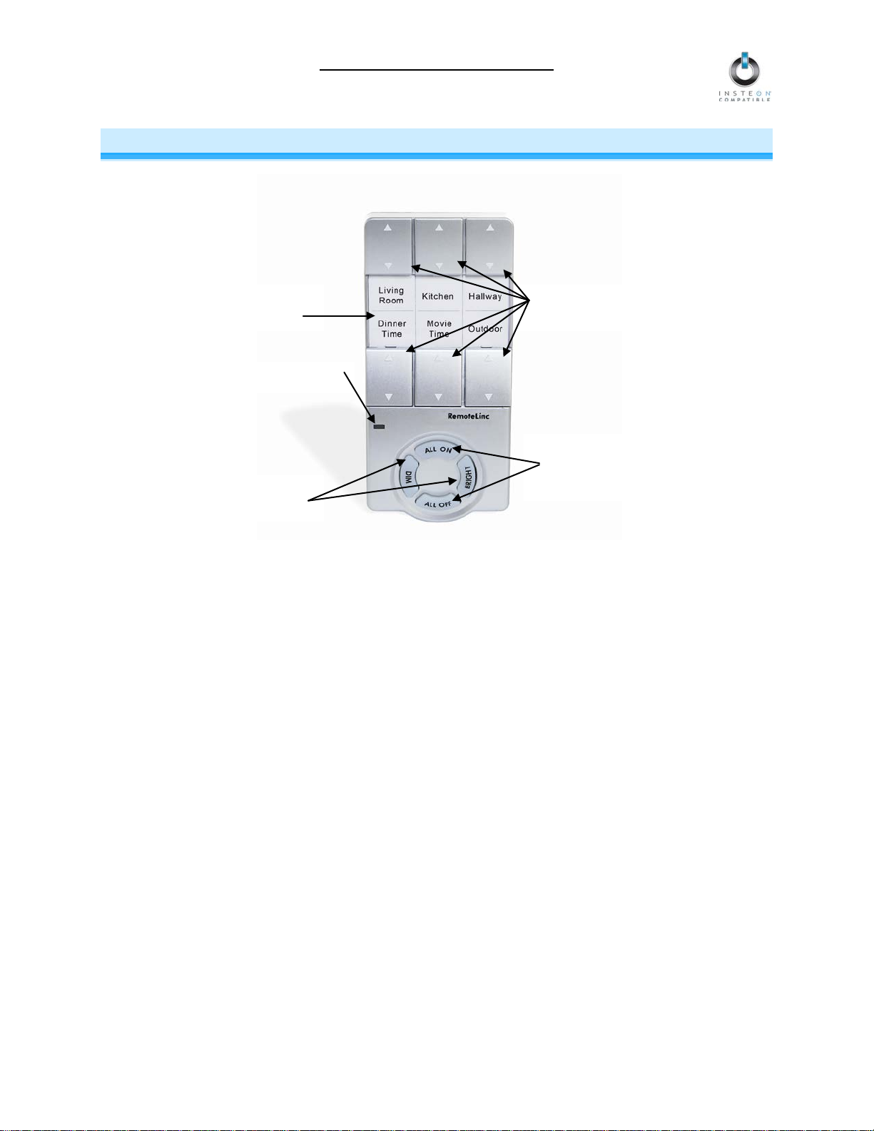
Dedicated
On/Off button
Dedicated
Status LED
Customizable
ABOUT REMOTELINC
Congratulations on purc hasing the INSTEON RemoteLinc. W ith its sleek, handheld design, Rem oteLinc
allows you to use the p ower of INSTEON to contr ol your home with t he convenience of a wireless radio
frequency (RF) controller.
label insert
pairs
Dim/Bright buttons
simultaneous-
control buttons
Key RemoteLinc Features
• Setup is easy – install four AAA batteries (included), and then Link to other devices in minutes
• Six individual On/Off button pairs, plus dedicated Dim, Bright, All On and All Off buttons
• Shows command transmission activity with a Status LED and beeper (both features easily
disabled/re-enabled)
• Stores setup state in memory so settings aren’t lost when batteries are removed
• Smart circuitry detects abnormally long button presses (like those occurring when the remote falls
between couch cushions) and puts RemoteLinc into sleep mode to preserve battery life
• Two-year warranty
What is Included with RemoteLinc
• RemoteLinc – INSTEON Wireless Remote Control
• Four (4) AAA batteries
• Quick-Start Guide
Page 3 of 13
Page 4
RemoteLinc Owner’s Man u al
WHAT IS INSTEON?
Since its inception in 2005, INSTEON has becom e a best-selling home-control networking technology,
offering more reliability and flexibility than any other home management system on the market. INSTEON
systems are sim ple, reliable, a nd affor dable. Simple, because each device tak es mere minutes to install.
Reliable, because ever y INST EON dev ice work s as a network repeater, e nsurin g your c omm ands will not
be lost. Affordable, bec ause INST EON can be int egrated i nto any num ber of devic es easil y and at a ver y
low cost. An INSTEON home grows in value with each added INSTEON device, making life more
convenient, safe, and fun.
How Does INSTEON Work?
What makes INSTEON the most reliable home automation network is its dual-mesh network. INSTEON
devices use both radio frequency (RF) signals and the home’s existing wiring to talk to each other. In an
INSTEON network, every INSTEON device also acts as a repeater, receiving and sending every message to all
other devices in the network. So by integrating more INSTEON devices you will strengthen the network and
ensure no commands will be lost.
No central controller or networking setup is required with an INSTEON network. Simply install your devices and
then use a series of button presses or taps to Link your devices together. Throughout this Owner’ s Manual, you
may see the terms “Controller” or “Responder”. These generic INSTEON terms refer to the components of an
INSTEON scene, and are used on a scene-by-scene basis.
• Controller – sends INSTEON commands to other devices
• Responder – reacts to commands sent out by another INSTEON device
An INSTEON device may act as a Controller, Responder, or sometimes both.
INSTEON networks are also extremely secure. Each INSTEON device is assigned a unique INSTEON ID, s o
unless neighbors or would-be hackers have access to your particular device’s INSTEON ID, they won’t be able
to control your home, even if they are using similar products.
INSTALLATION
Installing RemoteLinc
1) RF-only devices require at least one Access Point (#2443) or dual-band INSTEON device for
communication. For the best INSTEON network perf ormance, be sure you have properl y installed at
least two dual-band INSTEON devices.
Search for dual-band INSTEON devices at: www.smarthome.com/dualband
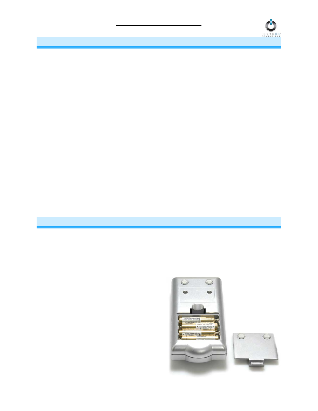
2) Remove the battery compartment from the rear
of RemoteLinc
3) Observe the polarity markings, and then install
four AAA batteries (included) accordingly
NOTE: Use alkaline batteries, or high quality
rechargeable batteries. A fully-charged set of
alkaline batteries will provide approximately
1,500-2,000 button taps.
4) Replace the battery compartment door before
use
Page 4 of 13
Page 5

RemoteLinc Owner’s Man u al
Button
Tap
Double-tap
Press & hold
On
Ramp to On-Level
Full-bright instantly
Brighten until released
Off
Ramp to Off
Full-off instantly
Dim until released
Button
Tap
Press & hold
Bright
Brighten a little
Brighten until released
Dim
Dim a little
Dim until released
Button
Tap
Press & hold
All On
Ramp to On-Level
Brighten until released
All Off
Ramp to Off
Dim until released
USING REMOTELINC
Using the RemoteLinc Buttons
On/Off Button Pairs
The On/Off button pairs will each contr ol any Respo nders Linked s pecificall y to the pair. R esponders will
behave differently depending on whether you tap, double-tap, or hold down the buttons.
Bright/Dim Buttons
The Bright and D im buttons wil l adjust the brightness of the Respo nders Link ed to the last O n/Off button
pair you used. (Non-dim ming Responders will not be affec ted.) Pressing & holding the Bright and Dim
buttons will adjust the bri ghtness contin uously, while tapp ing the buttons will adjust the brig htness one of
32 steps for each tap.
All On/All Off Buttons
The All On and Al l Off but tons can be used to turn all of the Respond ers Link ed to Re moteL inc on or off,
no matter which On/Off butt on pair they are Linked to. The All On button can als o be used to brighten al l
dimmable Responders, while the Dim button can be used to dim all dimmable Responders.
Creating a Custom RemoteLinc Label
Downloadable templates are available for easy customization of the RemoteLinc label.
To download the template in Microsoft Word, go to:
http://wiki.smarthome.com/images/5/5b/2440temp.doc
To download the template in Mircrosoft Excel, go to:
http://wiki.smarthome.com/images/4/45/2440_RemoteLinc_Label.xls
Page 5 of 13
Page 6

RemoteLinc Owner’s Man u al
BE CAREFUL
CONTROLLING INSTEON RES P O NDERS FROM S WITCHLINC DIMMER
Linking RemoteLinc to an INSTEON Responder
To use RemoteLinc as an INSTEON Controller, follow these steps to Link RemoteLinc and an INSTEON
Responder (the device you wish to control with RemoteLinc) together. Refer to the Responder’s Owner’s
Manual for detailed instructions on how to properly install and Link it to RemoteLinc.
The following will work for the most common INSTEON devices:
1) At the Responder, set it to the state you wish to be activated from RemoteLinc (turn it on if you wish it to be
on, or off if you wish it to be off when RemoteLinc activates the scene, set On-Levels, etc.)
• If the Responder is a multi-scene device (e.g., KeypadLinc), tap the Scene button you wish to
control until its LED illuminates
2) Choose the On/Off button pair you want to use to control your Responder.
There are six On/Off button pairs, labeled Scene A through Scene F. You can Link multiple Responders to
a single On/Off button pair.
3) Set RemoteLinc to Linking Mode by pressing & holding the On button of the pair until it beeps(10 seconds)
The RemoteLinc Status LED should begin blinking
You will have 4 minutes to complete the next step before Linking Mode automatically times out.
4) Press & hold the Responder's Set button for 3 seconds
RemoteLinc should beep and its Status LED should stop blinking and turn off
5) Confirm that Linking was successful by tapping the On/Off buttons you just Linked to on RemoteLinc
The Responder should respond appropriately
6) If you wish to Link multiple Responders to the same RemoteLinc, either repeat steps 1-4 with each
Responder or see Multi-Linking and Multi-Unlinking
Any accidental button presses will exit Linking Mode early.
Unlinking an INSTEON Responder from RemoteLinc
If you are no longer going to use an INSTEON Responder that has previously been Linked to RemoteLinc, it i s
very important that you Unlink it. Otherwise, RemoteLinc will retry any commands repetitively, thus slowing
down the system.
The following will work on the most common INSTEON devices:
1) If the Responder is a multi-scene device, tap the Sc ene button you wish to remov e control from until its
LED illuminates
2) Set RemoteLinc to Linking Mode by pressing & holding the On button of the pair you wish to Unlink until it
beeps (10 seconds)
The RemoteLinc Status LED should begin blinking
3) Set RemoteLinc to Unlinking Mode by pressing & holding the same On button until it beeps (10 seconds)
The RemoteLinc Status LED should continue blinking
You will have 4 minutes to complete the next step before Unlinking Mode automatically t i mes out.
4) Press & hold the Responder’s Set button for 3 seconds
RemoteLinc should beep and its Status LED should stop blinking and turn off
5) Confirm that Unlinking was successful by tapping the On/Off buttons you just Unlinked from on the
RemoteLinc
The Responder should no longer respond
Page 6 of 13
Page 7

RemoteLinc Owner’s Man u al
CREATING AN INSTEON SCENE
INSTEON scenes let you ac tivate dram atic li ghting m oods w ith the press of just one button. For ex am ple,
you can set all the lights in a scene to dim to 50% or tur n certai n lights o n wh ile tur ning oth ers of f, all with
the tap of a button on a C o ntrol ler.
INSTEON scenes are ver y easy to set up – just Link more than one Res ponder to the same On/Off or
Scene button on a Controll er. T hen, whe n you press any of the L inked buttons on the C ontr o ller , al l of the
INSTEON devices Linked in the scene will respond as a group.
To set up an INSTEON scene, you can individually Link each device to a Controller. Or, save time and
create multiple Links. See Multi-Linking and Multi-Unlinking.
ADVANCED FEATURES
Multi-Linking and Multi-Unlinking
Multi-Linking
Multi-Linking Mode al lows you to Link m ultiple IN STEON devices t o a sing le Con troller and quickl y create
an INSTEON scene. Once the Controller is in Multi-Linking Mode, you can Link any number of
Responders, one right after the other.
The following will work for the most common INSTEON devices:
1) For each of the Responders you wish to control, set t he device to the state you wish to activate f rom
the Controller
• If the Responder is a dimmable device, set the On-Level and Ramp Rate
• If the Responder is a multi-scene device (e.g., another Keypad), tap the desired Scene button
to illuminate the LE D. (If you wish the Responder ’s scene to turn off, tap the Scene button
again to turn the LED off, and then proceed to the next step.)
2) Set the Controller to Linking Mode. (For most Controllers, press & hold the desired On or Scene
button for 10 seconds or the Set button for 3 seconds.)
3) Tap the Set button on the Controller. If the Control ler does not hav e a Set butto n, tap the same On or
Scene button you used to put the Controller into Linking Mode.
Multi-Linking Mode will automatically time out after 4 minutes of inactivity.
4) One at a time, press & hold each of the Responder’s Set buttons for 3 seconds
5) After you have Linked all the desire d Respond ers, tap the Co ntroller ’s Set bu tton to ex it Multi-Linking
Mode. If the Controll er doe s not ha ve a Set butt on, ta p the sam e O n or Sce ne b utton you use d to put
the Controller into Linking Mode.
6) Test that the INSTEON scene is working as ex pected by tappin g the button you just Li nked to on the
Controller
Page 7 of 13
Page 8

RemoteLinc Owner’s Man u al
Multi-Unlinking
Multi-Unlinking Mode c an be used to qu ickl y remove devic es from an INSTEON s cene. You m ay remove
as many of the Linked Responders from the scene as you would like.
The following will work for the most common INSTEON devices:
1) Set the Controller to U nlinking Mode. (For most C ontrollers, press & hold the d esired On or Scene
button for 10 seconds twice or the Set button for 3 seconds twice.)
2) Tap the Set button on the Controller. If the Control ler does not hav e a Set butto n, tap t he sam e On or
Scene button you used to put the Controller into Unlinking Mode.
Multi-Unlinking Mode will automatically time out after 4 minutes of inactivity.
3) For each of the Responders you wish to Unlink:
• If the Responder is a multi-scene de vice (e.g., Ke ypad Linc ), ta p the Scene button you wish to
Unlink
• Press & hold the Responder’s Se t button for 3 seconds
4) After you have Unlinked the desired Responders, tap the Controller’s Set button to exit MultiUnlinking Mode. If the Controller does not have a Set button, tap t he same On or Scene button you
used to put the Controller into Unlinking Mode.
5) Test that you have removed the desired devices from the INSTEON scene by tapping the buttons you
just Unlinked from on the Controller
Enabling / Disabling the Beeper
This procedure will to ggle t he RemoteLinc beeper on and of f. W ith the beep er tur ned of f , RemoteLinc will
no longer beep during butt on presses. However, t he beeper will still sound w hen Rem oteLinc enters and
exits setup modes. By default, the beeper is on.
1) Simultaneously press & hold the Dim and Bright buttons until it beeps (10 seconds)
The RemoteLinc Status LED should begin blinking
2) Tap the Bright button
RemoteLinc should double-beep and its Status LED should turn on solid
The beeper is now disabled and will no longer beep upon button presses until re-enabled.
To re-enable the beeper, repeat steps 1 and 2.
Enabling / Disabling the Status LED
This procedure toggles the RemoteLinc Status L ED on and off. With the Stat us LE D turned off, the Status
LED will no longer flash during button presses. However, the Status LED will still function when
RemoteLinc enters and exits setup modes. By default, the Status LED is on.
1) Simultaneously press & hold the Dim and Bright buttons until it beeps (10 seconds)
The RemoteLinc Status LED should begin blinking
2) Tap the All Off button
RemoteLinc should double-beep and its Status LED should turn off
The Status LED is now disabled and will no longer flash or turn on solid until re-enabled.
To re-enable the Status LED, repeat steps 1 and 2.
Page 8 of 13
Page 9

RemoteLinc Owner’s Man u al
Stuck Button Feature
If any button on RemoteLinc is depressed for longer than 60 seconds, the Controller will enter sleep
mode until the button is released. This f eature is provided to preserve the batter y l ife in situations like
RemoteLinc falling between sofa cushions.
Restoring Power to RemoteLinc
RemoteLinc stores all of its settings, suc h as Links to other INSTEO N devices, On-Levels/Ramp Rates,
etc., with non-volatile memor y. Because settings are saved in this non-volatile memory, they will not be
lost when the batteries are rem oved.
Resetting RemoteLinc to its Factory Default Settings
The factory reset procedure will clear RemoteLinc of all INSTEON Links.
1) If you are using RemoteLinc to control any INSTEON devices, Unlink those devices from
RemoteLinc. See Unlinking an INSTEON Responder from RemoteLinc.
2) Remove a single battery from RemoteLinc for at least 10 seconds
3) While holding down the Bright button, reinsert the battery into RemoteLinc (ensure the battery is
properly oriented), making sure not to let up on the Bright button
RemoteLinc should beep and its Status LED should turn on solid
4) Once the battery has been reinserted, continue to hold down the Br ight button f or about 10 seconds,
and then release
While the Bright button is held down, RemoteLinc should beep continuously
Once the Bright button is rele ased, RemoteLinc should double-beep and its Status LED s hould
turn off
Page 9 of 13
Page 10

RemoteLinc Owner’s Man u al
ABOUT INSTEON
Using Dual-Band INSTEON Devices to Upgrade Your Network
What are phases?
The majority of single-family homes in North America have two phases (or “legs”) of 110 Volts coming into their
electricity panels. From the panel, they are distributed throughout the home, providing power to outlets and wall
switches. These phases come together in some parts of the home to provide 220 Volts of power to large
appliances, such as an electric oven or pool pump.
Why do I need to bridge these phases?
Single-band power line devices send commands via the home’s electricity, but only on a single phase. If the
command is intended for a device on the opposite phase, there is a good chance the command will go
unnoticed. Installing dual-band INSTEON devices, such as Access Points (#2443), on each phase will allow for
devices to communicate between the two phases via RF.
Dual-band INSTEON devices embody the full potential of a true INSTEON mesh network. Taking the power
line band signal and working in conjunction with the RF band signal, its dual-band function plays out in two
ways:
• Phase bridger – a receiver of commands, reacting to and translating signals sent from one power
phase to the opposite via RF
• Signal repeater – a participant in an INSTEON network, repeating commands intended for other
devices whether those commands are generated from RF or power line-only devices. To ensure
reliability, every INSTEON device confirms that it has received a command. If a Controll er does not
receive this confirmation, it will automatically retransmit the command up to five times.
While using at least one dual-band device is required when using an RF-only device, at least two dual-band
devices are recommended to ensure reliable communication across two-phase home wiring systems. For
larger applications, it is recommended to install at least one dual-band device for every 750 – 1,000 square
feet.
Search for dual-band INSTEON devices at: www.smarthome.com/dualband
Important Note about INSTEON Networks; Split Single-Phase vs. 3-Phase Installation
For the best INSTEON network performance, be sure you have properly installed at least two dual-band
INSTEON devices. INSTEON has only been officially tested in a split single-phase residential environment but
has been known to work in many 3-phase systems, where three dual-band devices are used (one on each
phase). However, due to the potential complexity of its troubleshooting, the INSTEON Gold Support Line is
unable to support INSTEON in 3-phase environments.
Further Enhancing Reliability
As signals travel via the power line or RF throughout the home, they naturally beco me weaker the farther they
travel. The best way to overcome weakened signals is to increase the coverage of the mesh network by
introducing more INSTEON devices.
It is possible that some audio-video devices, computers, power strips, or other electrical equipment may
attenuate INSTEON signals on the power line. You can temporarily unplug suspected devic es to test whether
the INSTEON signal improves. If it does, then you can plug in filters that will permanently fix the problem.
ADDITIONAL RESOURCES
Find home automation solutions, helpful tips, interactive demos, videos, user forums, and more at the
Smarthome Learning Center: www.smarthome.com/learningcenter.html
Page 10 of 13
Page 11

Problem
Possible Cause
Solution
RemoteLinc wil l not go
Mode.
Be sure to hold down the O n button for at least 10 seconds
blinking.
The RemoteLinc Status
on RemoteLinc.
All of my Responders do
buttons.
The Bright and Dim but tons
pair pressed on Remot eLinc.
Remove the batteries from RemoteLinc for 10 seconds, and
then reinstall.
Install a fres h set of batteries.
If the above doesn’t w ork, perform a factory reset. See
Resetting RemoteLinc to its Factory Default Settings.
TROUBLESHOOTING
RemoteLinc Owner’s Man u al
The Status LED on
RemoteLinc is not turning
on at all.
into Linking or Unl inking
RemoteLinc won’t Link or
work with a Responder .
Responders are t aking a
long time to respond to
RemoteLinc.
RemoteLinc can t urn off
my Responder, but
nothing happens wh en I
send an ON command
from RemoteLinc.
Batteries may be mi ssing or
depleted.
The Status LED might have
been disabled.
You didn’t hold the On button
down long enough.
The Responder may not be
receiving the RF com m and.
RemoteLinc may be out of
wireless range or the
INSTEON signal may b e too
weak.
RemoteLinc may be sending
commands to a Respon der that
is no longer in use. C om m ands
for the unused Respo nder are
being resent and loading down
the signal.
The Responder may be Linked
at its off state.
Install four fresh batteries into RemoteLinc.
Re-enable the Status LED . See Enabling / Disabling the
Status LED.
or until RemoteLinc beeps and the Status LED begins
Be sure you have proper ly installed at l east one dual-band
INSTEON device.
Try using RemoteLi nc from a different location, closer to an
Access Point or other dual-band INSTEON device.
Add additional INSTEON devices or move around existing
INSTEON devices . All INSTEON devices act as INSTEON
network repeaters.
Unlink any unused Res ponders from RemoteLinc. HINT: If
you are using home aut om ation software, you can easily
check scene membership and eliminate unnecessary Links.
If the above doesn’t w ork, perform a factory reset. See
Resetting RemoteLinc to its Factory Default Settings.
Re-Link the Responder w hile the responding device is on.
See Linking RemoteLinc to an INSTEON Responder.
The beeper on
RemoteLinc does not w ork
when I press an On or Off
button on RemoteLi nc.
LED does not flash when I
press an On or Off but ton
not respond to the
RemoteLinc Bri ght or Dim
RemoteLinc is locked up.
If you have tried these solutions, reviewed this Owner’s Manual, and still cannot resolve an issue you are having with
RemoteLinc, pl ease call:
The beeper may have been
disabled.
The Status LED may have
been disabled.
only control Responders
Linked to the last O n/Off button
Fluctuating batt ery current may
have glitched RemoteLinc.
Re-enable the beeper. See Enabling / Disabling the Beeper
Re-enable the Status LED . See Enabling / Disabling the
Status LED.
Push the On button for the scene you want to control, and
then use the Bright and/ Dim buttons.
INSTEON Gold Support Line
800-762-7845
Page 11 of 13
.
Page 12

RemoteLinc Owner’s Man u al
SPECIFICATIONS, CERTIFICATION, AND WARRANTY
Specifications
View specifications for RemoteLinc at: www.smarthome.com/2440.html
FCC & Industry Canada Compliance Statement
This device complies with FCC Rules Part 15 and Industry Canada RSS-210 (Rev. 7). Operation is
subject to the following two conditions:
(1) This device may not cause harmful interference, and
(2) This device must accept any interference, including interference that may cause undesired
operation of the device.
Le present appare il est conforme aux CNR d'Industrie Canada applicables aux apparei ls radio exempts
de licence. L'exploitation est autorise aux deux conditions suivantes :
(1) l'appareil ne doit pas produire de brouillage, et
(2) l'utilisateur de l'app areil doit accepter tout br ouillage radiolectriq ue subi, mme si le brouillag e est
susceptible d'en compromettre le fonctionnement.
The digital circuitr y of th is dev ice has been t ested and found to com pl y with the lim its for a Class B di gital
device, pursuant to Par t 15 of the F CC Rul es. T hese l im its ar e designed to pro vid e reason able pr otecti on
against harmful interfer ence in residential installations . This equipment generate s, uses, and can radiate
radio frequency energy and, if not installed and used in accordance with the instructions, may cause
harmful interference to ra dio and television reception. However, there is not guarante e that interference
will no occur in a particul ar installat ion. If this devic e does c ause such interferenc e, which can be verif ied
by turning the device off and on, the user is encouraged to elim inate the interferenc e by one or more of
the following measures:
• Re-orient or relocate the receiving antenna of the device experiencing the interference
• Increase the distance between this device and the receiver
• Connect the device to an AC outlet o n a circuit different from the one that supplies power to the
receiver
• Consult the dealer or an experienced radio/TV technician
WARNING: Changes or modifications to this de vice not expressly approved by the part y responsible for
compliance could void the user’s authority to operate the equipment.
Page 12 of 13
Page 13

RemoteLinc Owner’s Man u al
Limited Warranty
Seller warrants to the original purchaser of this prod uct that, for a period of two year s from the date of
purchase, this product will be free from defects in material and workmanship and will perform in
substantial conform ity t o the description of the product in this Owner’s Manua l. This warranty shall not
apply to defects or errors caused by misuse or neglect. If the product is found to be d efective in m aterial
or workmanship, or if the product do es not p erf orm as warranted ab ove dur ing the warra nty period, Sel ler
will either repair it, re place i t, or ref und th e purchas e pric e, at its opt ion, upon receipt of the produc t at the
address below, postage pr epaid, with proof of the date of purchas e and an explanation of the defect or
error. The repair, replacement , or refund that is provided f or above shall be the full extent of the Seller ’s
liability with respect to this product. For repair or replacement during the warranty period, call the
INSTEON Gold Support Line at 800-762-7845 with t he Model # and Revision # of the device to receive
an RMA# and send the product, along with all other required materials to:
Smarthome, Inc.
ATTN: Receiving Dept.
16542 Millikan Ave.
Irvine, CA 92606-5027
Limitations
The above warranty is in l ieu of and Seller disc laims all other warrant ies, wheth er oral or writt en, expres s
or implied, including any warranty or merchantability or fitness for a particular purpose. Any implied
warranty, including any warranty of m erchantability or f itness for a particular purpose, which m ay not be
disclaimed or supplanted as provided above shall be limited to the two-year of the express warranty
above. No other representation or claim of any nature by any person shall be binding upon Seller or
modify the terms of the above warranty and disclaimer.
Home automation devices have the risk of failure to operate, incorrect operation, or electrical or
mechanical tam pering. For optimal use, manuall y verify the device state. Any hom e automation device
should be viewed as a convenience, but not as a sole method for controlling your home.
In no event shall Seller be liable for special, incident al, consequential, or other dam ages resulting from
possession or use of this device, including without limitation damage to property and, to the extent
permitted by law, personal injury, even if Seller knew or should have known of the possibility of such
damages. Some states do not allow limitations on how long an implied warranty lasts and/or the exclusion
or limitation of dam ages, in which c ase the abo ve lim itations and/or exclus ions m ay not app l y to you. You
may also have other legal rights that may vary from state to state.
INSTEON Technology Patent
U.S Patent No. 7,345,998, International patents pending
© Copyright 2011
Smarthome, 16542 Millikan Ave., Irvine, CA 92606, 800-762-7845, www.smarthome.com
Rev 03-07-2011
Page 13 of 13
 Loading...