

DVB-S2 Meter
smartmeter S20
User Manual
Version: 18.01.2013 - English

User Information
Preface
Dear Customer,
Thank you for purchasing the digital DVB-S meter smartmeter S20.
This user manual contains all the information required
• to connect,
• to operate,
• to clean, and
• to dispose of the device.
Please read the user manual carefully before you start using the meter.
smart electronic GmbH
Industriestraße 29
78112 St. Georgen
Germany
Service Hotline: +49 (0) 7724 94 78 555
Telefax: +49 (0) 7724 94 78 333
E-Mail: service@smart-electronic.de
Internet: www.smart-electronic.de
© smart electronic GmbH 2013
All rights, technical changes, errors as well as printing mistakes reserved. Any reproducing or copying of
the contents requires prior written permission from smart.
2 smartmeter S20

User Information
Contents
1 User Information ............................................................................................................. 6
1.1 Use of this Manual ............................................................................................ 6
1.2 Signs, Symbols, Layout .................................................................................... 6
2 Product Description ....................................................................................................... 6
2.1 Scope of Delivery ............................................................................................. 7
2.2 Meter ................................................................................................................ 8
2.3 Guarantee ......................................................................................................... 9
3 Safety Notes .................................................................................................................. 10
3.1 Safety of persons............................................................................................ 10
3.2 Appropriate Usage ......................................................................................... 10
3.3 Hazards from Improper Use ........................................................................... 10
3.4 Lithium Polymer Battery ................................................................................. 11
4 Initial Setup ................................................................................................................... 12
4.1 Charging the Battery ...................................................................................... 12
4.2 Switching the Meter On and Off ..................................................................... 12
4.3 Entering and Exiting the Menu ....................................................................... 13
4.4 Navigating through the Menu ......................................................................... 13
5 Aligning the Satellite Dish ............................................................................................ 14
6 Menu TP Search ........................................................................................................... 15
6.1 Renaming a Satellite ....................................................................................... 15
6.2 Adding a Satellite ............................................................................................ 15
6.3 Deleting a Satellite .......................................................................................... 16
6.4 Searching for a Transponder .......................................................................... 16
6.5 Deleting a Transponder .................................................................................. 16
6.6 Adding a Transponder .................................................................................... 17
6.7 Searching Channels........................................................................................ 17
6.8 NIT .................................................................................................................. 18
7 Menu Satellite Identify .................................................................................................. 18
8 Menu Packet Control ................................................................................................... 19
8.1 Showing Measurement Values of five Transponders ..................................... 19
8.2 Searching Channels........................................................................................ 20
smartmeter S20 3

User Information
9 Menu DiSEqC Search .................................................................................................. 20
10 Menu DiSEqC Motor Search ....................................................................................... 21
10.1 DiSEqC 1.2 ..................................................................................................... 22
10.2 USALS ............................................................................................................ 22
11 Menu Spectrum ............................................................................................................ 22
12 Menu Watch Program .................................................................................................. 23
12.1 Selecting a Channel ....................................................................................... 24
12.2 Sorting the Channel List ................................................................................ 24
12.3 Switching Between TV Channel List and Radio Channel List ....................... 25
12.4 Deleting a Channel from the Channel List ..................................................... 25
13 Menu Settings .............................................................................................................. 25
13.1 Hiding the OSD .............................................................................................. 25
13.2 Switching off the Screen ................................................................................ 25
13.3 Setting Display Brightness ............................................................................. 26
13.4 Selecting Energy Unit .................................................................................... 26
13.5 Setting Volume Level ..................................................................................... 26
13.6 Switching On/Off the Beeper ......................................................................... 26
13.7 Activating the Automatic Standby Function .................................................. 26
13.8 Selecting the OSD Language ......................................................................... 26
13.9 Restoring Factory Settings ............................................................................ 26
14 Menu PC Update .......................................................................................................... 26
14.1 Showing the Software Version ....................................................................... 27
14.2 Performing a Software Upgrade .................................................................... 27
14.3 Editing the Channel List ................................................................................. 28
15 Saving a Screenshot .................................................................................................... 29
15.1 Capturing a Screenshot ................................................................................. 29
15.2 Displaying a Screenshot ................................................................................ 29
16 Operation in a Unicable System ................................................................................. 30
16.1 About Unicable .............................................................................................. 30
16.2 Allocation of IF channels and frequencies ..................................................... 31
16.3 Installation ...................................................................................................... 31
4 smartmeter S20

User Information
17 Cleaning the Meter ....................................................................................................... 32
18 Transporting and Storing the Meter ........................................................................... 32
19 Troubleshooting ............................................................................................................ 32
20 Disposal ......................................................................................................................... 33
21 Specifications ............................................................................................................... 33
21.1 General ........................................................................................................... 33
21.2 LNB/Tuner input ............................................................................................. 34
21.3 System Resources .......................................................................................... 34
21.4 Video Decoder ................................................................................................ 34
21.5 Data Interface ................................................................................................. 34
21.6 Power Supply ................................................................................................. 34
21.7 Dimensions and Weight .................................................................................. 34
21.8 Temperatur ..................................................................................................... 35
22 Declaration of Conformity ........................................................................................... 35
smartmeter S20 5

User Information
Symbol/layout
Meaning
You are requested to perform an action.
1.
List
The various possibilities of settings as well as image captions are stated
fett
bold
1 User Information
1.1 Use of this Manual
• This manual is intended for the DVB-S2 Meter smartmeter S20.
• Please carefully read this user manual before operating the device for the first time.
• Please note all warnings and notes included in this user manual.
• Consider this user manual to be an integral part of the product, and store it at a well
accessible location.
• This user manual should also be enclosed when handing over the device to a third party.
• In case of loss, the current version of the user manual can be downloaded at the support
center on our website www.smart-electronic.de.
• The software is still being further developed even after your purchase of the device.
Thus, it may be possible that certain operation steps do not fully correspond to the user
manual.
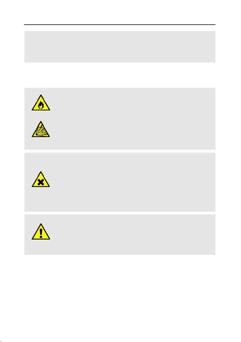
1.2 Signs, Symbols, Layout
WARNING
Danger due to electric shock with possible severe bodily injury
CAUTION
Warnung vor einem möglichen Sachschaden
NOTE
2.
kursiv
fett & kursiv
Useful information and hints
Perform these steps in the stated order.
in
Italics
.
The designations of keys are printed in
Menu windows and menu items (that often include further hidden menu
items or direct settings) are printed in
2 Product Description
The smartmeter S20 is a handy digital DVB-S2 measuring device for a quick and easy alignment of satellite antennas. If a satellite is found, the smartmeter S20 shows it on the display
and emits an audible signal. Signal strength and quality are displayed as numerical values
and bar graphs.
6 smartmeter S20
letters.
bold & italic
letters.

Product Description
Another measurement value is the forward error correction (FEC0F1), the carrier-to-noise ratio
(C/N), the bit error rate after Viterbi (VBER), and the Modulation error rate (MER
2
1F
). In addition,
the picture quality can be revised on the high-resolution 3.5-inch TFTLCD screen.
Many satellites are pre-programmed in order to allow a quick antenna adjustment.
There is a protective pouch for transport and as a protection.
2.1 Scope of Delivery
Please check if the delivery is complete.
Included in delivery:
• DVB-S2 Meter smartmeter S20
• 12 V plug-in power supply
• 12 V car adapter cable
• Quick-F connector
• Carrying bag
• User manual
If the delivery should be incomplete, contact your specialist dealer or the smart electronic
GmbH.
1
FEC = Forward Error Correction: In each data packet there are control bits. FEC 5/6 means, that there
are 5 data bits and 1 control bit. The better the ration between data and control bits, the less errors are at
the receiver's side. With FEC 3/4 the ratio is better than with FEC 5/6. Possible values are FEC 1/2, 2/3,
3/4, 5/6, 7/8 und 8/9.
2
Modulation error rate = all signal disturbances are summarized to one measurement value. The higher
the MER value, the better is the signal quality.
smartmeter S20 7
Product Description
1
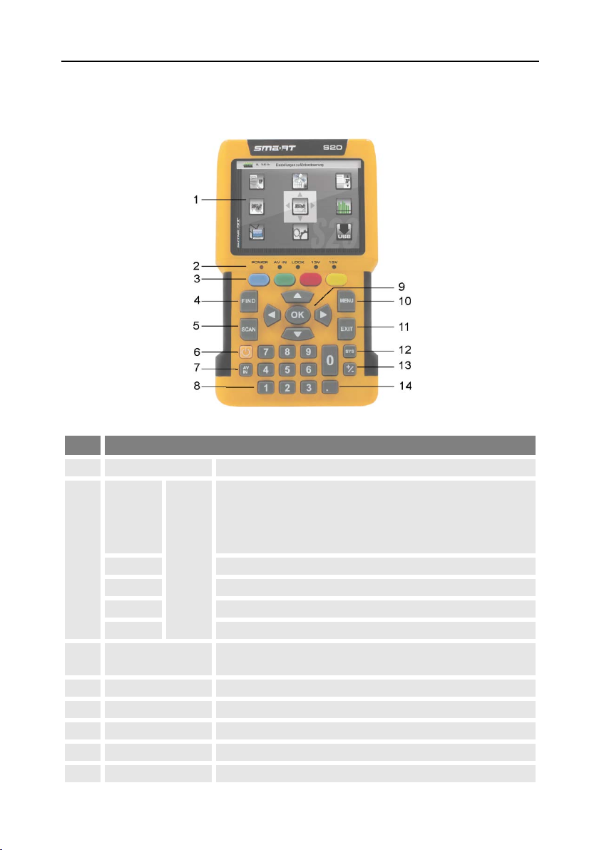
LC-Display
Display of the TV picture, the menu and the measured values..
• green the battery is fully charged
AV IN
Lights if the meter is switched to the analog video input.
LOCK
Lights when a signal is received.
13V
Lights if there is a 13 V signal for the polarization control (vertical)
18V
Lights if there is a 18 V signal for the polarization control (horizontal)
4
FIND
Call of the channel search function.
5
SCAN
Start of the automatic channel scan.
6
POWER
Switch device on/off.
7
AV IN
Switch to the analog video input.
8
Numeric keys
Direct entry of numbers.
2.2 Meter
2.2.1 Front View
No. Description
• green the meter is on
• off the meter is turned off
POWER
Charging:
• red during charging
2
3
FUNCTION keys
LED
Different functions depending on the menu.
The functions are displayed at the bottom of the screen.
8 smartmeter S20
Product Description
Cursor cross
Press to navigate through menus/submenus:
10
MENU
Display the main menu.
11
EXIT
Leave the current menu, cancel operation.
TV mode: call of the menu
OSD Setting
,
13
+/-
Call of the media player.
14 Pressing this key copies a screenshot to a connected USB disk.
1
Low-voltage socket (for power plug)
Switch for battery (for separating the smartmeter S20
electronics from the rechargeable battery)
No. Description
12
9
OK
SYS
Press ▲,▼ to switch between stations,
Press ◄,► to adjust the volume.
Press to confirm your selection / display station list.
Menu: volume control.
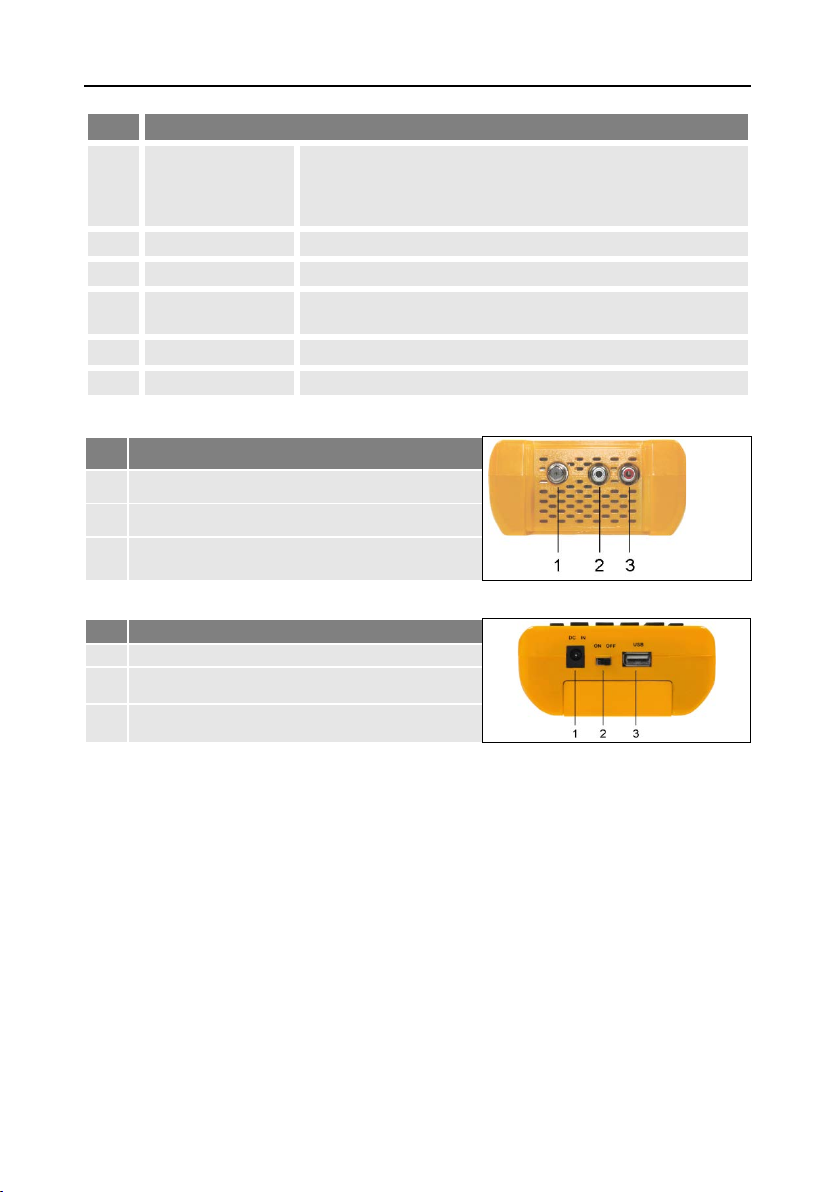
2.2.2 Top View
No. Description
1
Digital satellite signal input
2
Analog audio input (mono)
3 Analog video input (Composite Video)
2.2.3 Bottom View
No. Description
2
3
USB port for external data storage devices
The above figures show the smartmeter S20 without the black part covering at the top of the
device.
2.2.4 Rear View
At the rear is the battery compartment. Normally, you must not open it. If you suspect that
the lithium-polymer battery must be replaced, contact your dealer.
2.3 Guarantee
The digital meter smartmeter S20 of smart electronic GmbH comes with a guarantee in
accordance with legal requirements as applicable at the time of the purchase.
smartmeter S20 9

Safety Notes
3 Safety Notes
3.1 Safety of persons
Ensure that nobody can be hurt by falling tools or parts of the satellite antenna during the
adjustment and installation of the antenna. For your own security use a rope on sloping
roofs.
3.2 Appropriate Usage
The measuring device smartmeter S20 was developed to measure signals of digital satellite
antennas and satellite systems. It is exclusively for this purpose and should only be used for
this purpose. Use the equipment only for the purpose, which is described in this manual.
Any other usage is rated as not properly and can result in damage or even injury. There will
be no liability for damages caused by a non-intended use.
3.3 Hazards from Improper Use
Make sure the meter and especially the power plug are always kept
dry.
Do not expose the meter to temperatures below 0° C.
Connect the power plug only to 100-240 V AC, 50/60 Hz.
Charge the meter only with the supplied power plug.
During electrical storms, disconnect the meter from the aerial and
CAUTION!
from the power supply.
Do not put heavy objects onto the meter.
Avoid mechanical influences that can damage e.g. the LCD display or
the housing of the meter.
Do not bend or crimp the cables.
Do not start to use the meter if you can see signs of damage or if you
can hear loose parts inside the device.
Danger of electrical shock from high voltage
Damages on the housing of the power plug or an improperly repaired
WARNING!
10 smartmeter S20
power plug can expose the user to mains voltage.
Do not open the supplied power plug.
Have the power plug repaired by qualified personnel only.
Safety Notes
Fire and explosion hazard
Risk of injury
Damages to other objects
Taking the device from cold into warm temperatures can lead to condensation forming inside the device.
Do not connect the device instantly. Leave it switched off for a few
hours.
3.4 Lithium Polymer Battery
The smartmeter S20 is provided with a lithium polymer battery. Please observe the following
safety notes for the battery:
Any kind of heat (from inside or outside) can trigger uncontrollable
WARNING
WARNING
CAUTION!
chain reactions inside the battery.
Do not store or use the battery in temperatures above 40 °C.
Never connect the two poles (+ and -).
Never expose the battery to high temperatures, e.g. close to stoves or
cookers or other hot objects.
Charge the battery only with the supplied power plug.
Damages on and improper use of the battery can lead to fumes leaking from the battery. When inhaled, these fumes can irritate the respiratory tracts.
Avoid any damaging of the battery.
If fumes leak from the battery, open the window and seek medical
advice if you experience health problems that may result from inhaling
battery fumes.
Defective batteries can leak and spill battery liquid onto close-by ob-
CAUTION!
jects.
Check the objects affected.
Clean or, if necessary, replace the objects affected.
smartmeter S20 11

Initial Setup
4 Initial Setup
4.1 Charging the Battery
Charge the battery completely before you use the meter for the first
time.
An integrated automatic charging system ensures optimum charging of the battery.
Switch off the meter, if it is not yet switched off, to ensure that the complete power of the
power supply can be used to charge the battery.
Plug the power plug into a 230-V socket.
Connect the low-voltage plug of the power plug to the low-voltage socket on the bottom
of the meter.
The battery starts charging as soon as you connect the smartmeter S20 to the power plug.
The battery can be charged regardless of
• whether the meter is switched on or off or
• whether the battery-switch on the underside of the meter is set to
On or Off.
Basically, the meter is also charged if it is switched on, then the
charging period becomes longer.
When you charge the battery for the first time, charge it for at least
5 hours.
The maximum charging time is 12 hours.
4.1.1 Charge Control
• Charging is indicated by a continuously moving battery symbol in the display:
.
The POWER LED lights red..
• Completed charging is indicated by a steady battery symbol filled with four bars: .
The POWER LED lights green.
4.1.2 State of Charge
The current status of the battery is continuously displayed:
• If the battery is not adequately charged, the battery charging icon will be displayed in red
with 1 or 2 lines (corresponding to the state of charge). You should charge the battery.
• If the battery is sufficiently charged, the battery charging icon will be displayed in green
with 3 or 4 lines.
4.2 Switching the Meter On and Off
4.2.1 Switching On
1. Ensure that the battery-switch on the underside of the meter is set to an ON position.
2. Press the POWER key to switch on the meter. The POWER LED lights green.
12 smartmeter S20

Initial Setup
In case of disconnected power supply, the smartmeter S20 will be
turned on, once you put the battery switch from the OFF to the ON
position.
If the power supply is plugged in, the battery switch will be useless,
meaning that the smartmeter S20 can be switched on regardless of
the switch position.
4.2.2 Switching Off
Press the POWER key once again to switch off the meter after use.
For long operational pauses, please also separate the smartmeter S20
electronics from the battery by setting the battery switch on the underside of the device to the
OFF
position.
4.3 Entering and Exiting the Menu
Press MENU to enter the main menu. The display shows the OSD2F
The display shows the main menu window
when you switch the smartmeter S20 on
and when you re-enter the menu.
Press EXIT to exit the menu or to return
to the previous menu level.
3
main menu.
Depending on the submenu you are in, you may have to press the
EXIT key several times to return to the main menu.
4.4 Navigating through the Menu
Use the colored function keys and the navigation keys to navigate through the menu:
Press ► / the yellow function key to select the menu item to the right or to increase the
selected value.
Press ▼ / the red function key to select the menu item below.
Press ◄ / the blue function key to select the menu item to the left or to decrease the
selected value.
Press ► / the green function key to select the menu item above.
Press OK to enter the selected menu item.
Activated menu items are highlighted by color.
3
OSD = On Screen Display
smartmeter S20 13

Aligning the Satellite Dish
5150
5750
UnicableA (9750 - 10600)
5950
UnicableA (10200)
9750
UnicableB (9750 - 10600)
10000
UnicableB (10200)
10050
10450
The function keys may call different functions, dependent on the regarding menu.
Instead of changing a value by using the keys ► und ◄, with many
menu items you can also press the OK key, select a new value from the
list, and confirm such value by again pressing the OK key.
5 Aligning the Satellite Dish
1. Press MENU.
2. Use the keys ◄ / ► and ▲ / ▼ to select the menu item
selection with
OK
.
3. Select the desired satellite in the setting field with the keys ◄ / ►.
4. Go to
Possible values for
5. If you use a multifeed antenna, go to
LNB Freq
and select the right value for the used LNB. You also can change the
LNB frequencies with the blue function key.
LNB Freq
(MHz)
10600 Universal (9750 - 10600)
10700
10750
11250
11300
5150 - 5750
5750 - 5150
DiSEqC1.0
satellite. You also can change the DiSEqC1.0 port with the yellow function key.
6. If you can receive signals from more than four satellites select
port for the selected satellite. Factory setting is Disable.
7. Go to
Transponder
and use the keys ◄ / ► to select the transponder, broadcasting the
channel, which you want to use for adjusting your antenna. Signal strength and signal
quality (of the selected transponder) are displayed on the bottom of the window. Alternatively go to
Transponder
, press OK, select the corresponding transponder from the list
and confirm by pressing OK.
8. Turn the dish until the
signal quality. If the
LOCK LED
LOCK LED
In the menu
lights or the bar graph displays signal strength and
lights there is also an acoustic signal
OSD Setting
Beeper
signal should be output (On) or not (
9. Fixate the Dish in the position with the best signal strength.
TP SEARCH
and confirm your
and select the port for the selected
DiSEqC1.1
4
3F
and set the
you can set, whether an acoustic
Off
), if a signal is found.
4
DiSEqC1.1 supports 16 satellite positions
14 smartmeter S20

Menu TP Search
In the menu
a list of the stored
satellites is shown.
10 satellites are displayed on each page. To
display further satellites use the keys ▲ and
▼.
10. Vary the angle of inclination until the bargraph displays even more signal strength and
signal quality.
11. Press EXIT, several times to get to the TV mode. In the info window on the bottom of the
window signal strength
MER
(modulation error rate) are shown.
12. Fixate the Dish in the position with the best
6 Menu TP Search
Select the menu
OK.
TP Search
S
, signal quality
The
higher
aligned).
TP Search
Q, FEC, VBER
VBER
VBER
value with good reception is 10E-8 (so almost 0). The
VBER
is, the worse is the signal (e. g. antenna wrong
and press
(bit error rate after Viterbi), and
quality.
6.1 Renaming a Satellite
1. Select the satellite you’d like to rename in the list with the
keys ▲ and ▼.
2. Press the blue function key (Edit). A screen keyboard opens.
3. Give a new name for the satellite. Use the keys ◄/► and ▲/▼ to mark a character and
confirm each character with
4. Repeat until you have the desired name.
Press the blue function key (Delete) to delete the respectively selected character.
Press the yellow function key (CAPS) to switch between upper case and lower
case.
Press the red function key (Cancel) to discard the changes made so far and to
close the window
Press the green function key (OK) to accept the changes made so far and to close
the window
Rename
OK
Rename
.
.
.
6.2 Adding a Satellite
1. Press the green function key (Add). A screen keyboard opens.
2. Give a name for the new satellite. Use the keys ◄/► and ▲/▼ to mark a letter and
confirm each letter with
3. Repeat until you have the desired name.
Press the blue function key (Delete) to delete the respectively selected character.
smartmeter S20 15
OK
.

Menu TP Search
Press the yellow function key (CAPS) to switch between upper case and lower
Press the red function key (Cancel) to discard the changes made so far and to
Press the green function key (OK) to accept the changes made so far and to close
case.
close the window Rename.
the window Rename.
The transponder list of the new satellite is empty. Create a new
transponder as described below (Adding a new Transponder).
6.3 Deleting a Satellite
1. Select the satellite you’d like to delete from the list with
the keys ▲ and ▼.
2. Press the red function key (Delete).
3. Use the keys ◄/► to mark the button
from the list.
Mark the button
leting the satellite.
No
and confirm with OK to go back to the menu
Yes
and confirm with OK to delete the satellite
TP Search
, without de-
6.4 Searching for a Transponder
Select with the keys ▲ and ▼the satellite
on which you’d like to look for a transponder.
Press
With the keys ◄ and ► you can know
OK
.
change once more the satellite.
Go to
If you use a multifeed antenna, go to
If you can receive signals from more than four satellites select
6.5 Deleting a Transponder
1. Select in the sub menu
2. Select with the keys ▲ and ▼the line
3. Select with the keys ▲ and ▼the Transponder you want to delete and press OK.
4. Press the red function key (Del).
16 smartmeter S20
LNB Freq
listed in the section “Aligning the Satellite Dish”. You also can change the LNB frequencies with the blue function key.
satellite. You also can change the DiSEqC1.0 port with the yellow function key.
DiSEqC1.1
like to delete a transponder and press OK. With the keys ◄ and ► you can know change
once more the satellite.
and select the right value for the used LNB. The possible values are
DiSEqC1.0
and set the port for the selected satellite. Factory setting is Disable.
TP search
with the keys ▲ and ▼the satellite on which you’d
Transponder
and select the port for the selected
and press OK.

Menu TP Search
5. Use the keys ◄/► to mark the button
Yes
and confirm with OK to delete the transponder from the list.
Mark the button
No
and confirm with OK to go back to the menu
TP Search
, without de-
leting the transponder.
6.6 Adding a Transponder
1. Select in the sub menu
like to add a transponder and press OK. With the keys ◄ and ► you can know change
once more the satellite.
2. Select with the keys ▲ and ▼the line
3. Select with the keys ▲ and ▼the last position
window
Add TP
Select with the keys ▲ and ▼the line
the frequency (in MHz) of the new transponder.
Select with the keys ▲ and ▼the line
the symbol rate (in kS/s) of the new transponder.
Select with the keys ▲ and ▼the line
polarization of the new transponder.
H
= horizontal
V
= vertical
4. Press the green function key (OK) to confirm the new transponder.
opens.
TP search
with the keys ▲ and ▼the satellite on which you’d
Transponder
Frequency
Symbol Rate
Polarity
and press OK.
New TP
in the list and press OK. The
and insert with the numeric keys
and insert with the numeric keys
and insert with the keys ◄ and ► the
6.7 Searching Channels
1. Select in the sub menu
you’d like to look for receptable channels and press OK.
2. Go to
Transponder
which you’d like to look for receptable channels and press OK.
3. Go to
LNB Freq
listed in the section “Aligning the Satellite Dish”. You also can change the LNB frequencies with the blue function key.
4. If you use a multifeed antenna, go to
satellite. You also can change the DiSEqC1.0 port with the yellow function key.
5. If you can receive signals from more than four satellites select
DiSEqC1.1
and set the port for the selected satellite. Factory setting is
6. Press the green function key to go to the search window:
Select
Only FTA
or for all channels (
Select at
Scan Channel
radio channels or for TV + radio channels..
Select at
Network Search
channels of a channel network (
Press OK to start the channel search.
5
FTA = Free To Air = unencrypted channels
TP search
the satellite containing the transponder on which
and select with the keys ▲ and ▼from the list the transponder on
and select the right value for the used LNB. The possible values are
DiSEqC1.0
and select the port for the selected
Disable
5
4F
to determine if scan should be made only for FTA channels (
No
).
if you want to perform scan only for TV channels, only for
if you want to search for an individual channel (No) or all
Yes
), e.g. PRO7, SAT1, KABEL1, SIXX.
.
Yes
)
smartmeter S20 17

Men
u Satellite Identify
1.
2.
Press the red function key to stop the search at any time.
Found programs are attached to the rear of the channel list.
6.8 NIT
The smartmeter S20 is equipped with NIT. NIT means Network Information Table and is
transmitted in the data stream of the satellite. It contains data regarding to transponders and
channels, such as frequency, sound carrier or symbol rates.
To align a satellite antenna you can also use the NIT display. When a signal is found worthy
to receive, the NIT display tells you to which satellite your antenna is actually aligned.
Examples:
NIT
NIT
In order that a satellite can be found, the remaining data, especially transponder data and DiSEqC port must be correct.
7 Menu Satellite Identify
In TV mode press the MENU key (or
navigate to main menu).
Select the sub menu
and confirm with OK.
18 smartmeter S20
Satellite Identify

Menu Packet Control
1.
2.
3.
3. Go to
4. If you use a multifeed antenna, go to
5. If you can receive signals from more than four satellites select
You can see on the screen, which satellite is currently received. Also, signal strength and
signal quality are displayed.
LNB Freq
listed in the section “Aligning the Satellite Dish”. You also can change the LNB frequencies with the blue function key.
satellite. You also can change the DiSEqC1.0 port with the yellow function key.
DiSEqC1.1
EqC1.1 port with the red function key. Factory setting for
and select the right value for the used LNB. The possible values are
DiSEqC1.0
and set the port for the selected satellite. You also can change the DiS-
Satellity Identify
meter S20.
uses the transponder lists stored in the smart-
and select the port for the selected
DiSEqC1.1
is
Disable
.
8 Menu Packet Control
In this menu you can
• display signal strength and signal quality of five consecutive transponders
as well as
• perform a channel search.
8.1 Showing Measurement Values of five Transponders
In TV mode press the MENU key (or
navigate to main menu).
Select with the keys ◄/► and ▲/▼ the
sub menu
with OK.
Select at
the satellite where you can find the transponders to display.
4. Go to
listed in the section “Aligning the Satellite Dish”. You also can change the LNB frequencies with the blue function key.
5. If you use a multifeed antenna, go to
satellite. You also can change the DiSEqC1.0 port with the yellow function key.
6. If you can receive signals from more than four satellites select
DiSEqC1.1
You can see on the screen signal strength
sponders.
Press the red function key (Next TPs) to display the values of the next five transponders
in the transponder list.
Packet Control
Satellite
LNB Freq
and select the right value for the used LNB. The possible values are
and set the port for the selected satellite. Factory setting is
and confirm
with the keys ►and ◄
DiSEqC1.0
and select the port for the selected
S
and signal quality Q of five consecutive tran-
Disable
.
smartmeter S20 19

Menu DiSEqC Search
1.
2.
8.2 Searching Channels
Press the green function key to open the window
can search for channels on one satellite.
You also can reach the window
Select at
Satellite
ing of the key SCAN.
with the keys ◄ and ► the satellite on which you want to perform the
scan.
Select
Only FTA
all channels (
Select at
6
5F
to determine if scan should be made only for FTA channels (
No
).
Scan Channel
if you want to perform scan only for TV channels, only for radio
channels or for TV + radio channels..
Select at
channels of a channel network (
work Search
Select the scan mode at the menu item
−
Network Search
is only active, if you selected the
Preset Scan
if you want to search for an individual channel (No) or all
Yes
), e.g. PRO7, SAT1, KABEL1, SIXX. The item
Scan Mode
(Standard Scan): considering only the frequencies included in the TP list
(of the regarding satellite).
−
Auto Scan
(Blind Scan): considering all frequencies, regardless of whether they are
included in the TP list or not.
Press the green function key to start the channel scan.
Press the red function key to stop the search at any time.
Single Satellite Search
Single Satellite Search
Scan Mode Preset Scan
:
where you
.
by press-
Yes
) or for
Net-
9 Menu DiSEqC Search
In this menu you can scan the DiSEqC switch. As result of the scan you see on which port
which Satellit is received.
In TV mode press the MENU key (or
navigate to main menu).
Select the sub menu
confirm with OK.
DiSEqC Search
and
6
FTA = Free To Air = unencrypted channels
20 smartmeter S20

Menu DiSEqC Motor Search
The DiSEqC search begins automatically. One
after another, all four DiSEqC1.0 ports are
scanned. After completing the scan, the
screen might look like this:
DiSEqC1.0
DiSEqC1.1
1.
2.
DiSEqC Motor
Press the blue function key to select the
right frequency for the used LNB.
Press the green function key to switch
between
und
.
10 Menu DiSEqC Motor Search
This menu is used to set up a motor antenna and its control system.
In all menu windows (e. g. moving dish) you see signal strength
In TV mode press the MENU key (or
navigate to main menu).
Select the sub menu
Search
and confirm with OK.
Press the blue function key to turn the satellite dish to the west.
Press the yellow function key to turn the satellite dish to the east.
Press the green function key to start a channel search for the current transponder (see
section 6.7 „Searching Channels“). Since you use DiSEqC1.2 or USALS for the antenna
control, normally you can ignore the lines
DiSEqC1.0
cases (e. g. cascading of DiSEqC switches) where additionally to DiSEqC1.2 you need
DiSEqC1.1
.
Press the red function key to set the
details for the motor control:
Select at
Satellite
with the keys ◄
and ► the satellite for the following
settings should be valid.
S
and signal quality Q.
and
DiSEqC1.1
. There are special
Select
Transponder
to set the transponder which should be reference for the anten-
na position (generally the transponder which broadcasts your favorite channel).
Select
and
Motor Type
USALS
tings are available.
to set the used control technique. Select between
(depending on the used motor). Depending on your choice, different set-
smartmeter S20 21
DiSEqC1.2

Menu Spectrum
1.
2.
and
10.1 DiSEqC 1.2
Select
Select
Select
Then press OK to save the found position.
If necessary, repeat these steps for other satellites / transponders.
Select
Position No & Save
current antenna position) will be saved.
Go To X
is the zero position).
ence
Save
the maximum values of signal strength and signal quality which are shown at the bottom
edge of the screen.
to call a position from which you want start the settings (the value
and move the dish with the keys ► and ◄ to the west or the east. Look for
Recalculation
antenna positions. A query window opens. Confirm the deletion with the green function
key (Yes) or cancel it with the red function key (No).
to set a position number as which the current satellite (the
Refer-
and press OK to discard all settings and define once more the
10.2 USALS
Select Local Longitude to enter the longitude of your antenna’s position with the numer-
ic keys 0 ... 9.
Select Local Latitude to enter the latitude of your antenna’s position with the numeric
keys 0 ... 9.
11 Menu Spectrum
In this submenu, you can check the different transponders across the entire spectrum.
In TV mode press the MENU key (or
navigate to main menu).
Select the sub menu
confirm with OK.
Spectrum
Press the blue function key to switch the polarization between horizontal
(V)
.
Press the green function key to change the sample rate:
4 M: very exact scan,
8 M: middle precision
16 M: less precise
)
Press the red function key to select the DiSEqC port and thus the satellite.
Press the yellow function key to set the 22 kHz control voltage for the switch between
high band and low band:
22 smartmeter S20
The more accurate the scan, the longer it takes to capture the entire frequency range.
(H)
and vertical

Menu Watch Program
On
Permanent on,
Off
Permanent off,
Auto
automatic
The permanent settings are required, for example, for certain antenna systems or to avoid
interferences.
12 Menu Watch Program
To check the TV reception, you can put the smartmeter S20 in the TV mode.
In the main menu select the sub menu
Watch Program
press EXIT in the main menu to switch to
TV mode.
)
In addition to the live TV picture an infobar appears with the following information:
• Satellite, current date, current time
• Position in the current channel list, channel name with video PID, audio PID, PCR PID.
• Transponder data: frequency / symbol rate / polarization
• Error correction rate FEC
• Transmission standard, modulation
• Bit error rate VBER (bit error rate after error correction)
• Modulation error rate MER: all signal disturbances are summarized to one measurement
value. The higher the MER value, the better is the signal quality.
The MER can be worsened by these issues: Noise (C/N), Low frequency hum (50/100
Hz), Inter modulation errors (overridden amplifiers), I/Q modulation errors
(phase/amplitude), Signal overlap (DECT phone), Standing waves (maladaptation or unfavorably mounted cables)
• Signal strength S, signal quality Q
Press EXIT to open a toolbar (with four buttons) instead of the infobar.
Press the blue function key (Information) to open the infobar.
Press the green function key (Full Screen) to close the toolbar and to show only live
TV.
Press the red function key (Mute) to switch off the TV sound.
Press the yellow function key (Audio) to select the audio mode:
Use the keys ► and ◄ to select between:
and confirm with OK or
After the first switch-on (or after resetting to factory settings), no
programs are stored, the channel list is empty. You receive an error message: „No Channel!“
Left, Right, Stereo, Mono
smartmeter S20 23

Menu Watch
Program
and
the keys ▲ and ▼ to select another language or Dolby AC3 (Dolby Digital).
When selecting AC3 there is no TV sound. This option is only for
verifying such programs / channels.
12.1 Selecting a Channel
You have several possibilities to select a channel.
12.1.1 Direct Channel Selection
Select the desired channel by using the keys ▲ and ▼.
With each change of channel, an information window with information on the current channel
will be displayed (see above).
12.1.2 Channel Selection via Selection Window
1. Press the OK key to display a selection window with all available channels.
2. Select the channel list with the desired channel by using the keys ► and ◄. You can
select between a channel list for all satellites, channel lists for each satellite and you favorite lists.
3. Select the channel to be displayed by using the keys ▲ and ▼ and confirm your selec-
tion by pressing OK. The channel will be correspondingly switched.
You can create favorites lists only with the channel list editor (see
"edit channel list using the editor program", page 28)
12.1.3 Channel Selection via Search Function
The channel lists can be quite comprehensive; correspondingly, the smartmeter S20 offers
the possibility to search for channels in the list:
1. Press the FIND key to open the window Find with an on-screen-keyboard.
2. Select a character by using the keys ◄/► and ▲/▼ and respectively confirm by pressing OK to accept such character.
3. As soon as the first selected character has been confirmed by pressing OK, a second
window will open, showing all channels starting with this character (in most cases, the
first character is a letter).
Press EXIT to close the window Find, provided that selection is sufficiently arranged for
your purposes. Now, you can select the desired channel in the other window by using
the keys ▲ and ▼, and confirm by pressing OK.
4. Return to entry of characters (see step 2) to further limit channel selection.
12.2 Sorting the Channel List
1. In TV mode press OK.
2. Press the blue function key (Sort) to open a window for determining sorting criteria.
3. Select Name(A-Z) to sort the channel list in ascending alphabetical order or
Select Name(Z-A) to sort the channel list in descending alphabetical order or
24 smartmeter S20

Menu Settings
1.
2.
and confirm
Select Free/Scramble to first list all free channels and then all encrypted channels in the
channel list.
4. Press OK to confirm.
5. Press the yellow function key (Play) to go back to the TV mode.
12.3 Switching Between TV Channel List and Radio Channel
List
1. In TV or radio mode press OK.
2. Press the green function key (TV/Radio) to switch between TV channel list and radio
channel list (or vice versa).
3. Press the yellow function key (Play) to go back to TV mode or radio mode.
12.4 Deleting a Channel from the Channel List
1. In TV mode press OK.
2. Select with the keys ► and ◄ the channel list including the channel you want to delete.
If necessary, switch between TV channel list and radio channel list.
3. Select with the keys ▲ and ▼ the the channel you want to delete.
4. Press the red function key (Delete) to delete the channel. A safety query opens:
Press the green function key (Yes) to complete the deletion.
Press the red function key (No) to cancel the deletion and go back to the channel
list.
5. Press the yellow function key (Play) to go back to TV mode.
13 Menu Settings
In TV mode press the MENU key (or
navigate to main menu).
Select the sub menu
with OK. The window
Settings
OSD Setting
opens.
13.1 Hiding the OSD
Select
13.2 Switching off the Screen
Select
smartmeter S20 25
OSD Timeout
OSD should be hided. You can select values between
is
3
s.
Back Light Off
screen should be switched off. You can select values between
tory setting is
, to set with the keys ◄ and ► the number of seconds when the
1
and 10 seconds. Factory setting
to set with the keys ◄ and ► the number of minutes when the
5 Minutes
.
Off
and
30 Minutes
. Fac-

Menu PC Update
13.3 Setting Display Brightness
Select
Back Light Level
select values between
to set with the keys ◄ and ► the display brightness. You can
1
(dark) and 5 (light). Factory setting is 5.
13.4 Selecting Energy Unit
Select
Energy Unit
voltage measures during spectrum analysis. You can select between
Factory setting is
to set with the keys ◄ and ► in which unit you want to show the
dBµV
.
dBm
and
dBµV
13.5 Setting Volume Level
Select
Value
to set with the keys ◄ and ► the level of the TV sound plus the beeper
sound level when a signal is found. You can select values between
setting is
50
.
10
and
100
. Factory
13.6 Switching On/Off the Beeper
Select
Beeper
to set with the keys ◄ and ► whether there should be a beeper sound
when a satellite signal is found (
On
) or not (
Off
). Factory setting is On.
13.7 Activating the Automatic Standby Function
Select
Auto Standby
after which time the meter should go to standby mode, using the the keys ◄ and ►. You
can select values between
to switch on or switch off the automatic standby function, and if on
Off
und
3 Hours.
Factory setting is
3 Hours
.
13.8 Selecting the OSD Language
Select
Language
Factory setting is
to set with the keys ◄ and ► the OSD language.
Deutsch
.
.
13.9 Restoring Factory Settings
1. Select
2. Press the green function key (Yes) to complete the restore
14 Menu PC Update
The sub menu
port.
26 smartmeter S20
Factory Setting
or
press the red function key (No) to cancel the restore and go back to the menu window.
PC Update
and press OK to restore factory settings.
A factory reset will erase all channels in your channel list!
is mainly intended to update the operating software via the USB

Menu PC Update
1.
2.
Upgrade
is supplied during the
In TV mode press the MENU key (or
navigate to main menu).
Select the sub menu
PC Update
and
confirm with OK. The window
by USB
opens.
14.1 Showing the Software Version
Press the blue function key (Version) to display software and hardware version of your
smartmeter S20.
14.2 Performing a Software Upgrade
Make absolutely sure that the smartmeter S20
upgrade.
CAUTION!
1. Look for the current software release packed as a zip archive in the support area of
www.smart-electronic.de.
2. Unpack it and save the file with the extension *.abs on your USB disk.
3. Connect the USB disk to the smartmeter S20.
4. Select the line
5. Select the new software file (*. abs) (must be in the root directory of the connected USB
disk!).
6. Select the line
7. Make sure that the
by pressing the keys ◄ and ►. With
the "factory" channel list (default setting is empty) are newly loaded into the smartmeter
S20.
8. Use the keys ▲ and ▼ to select the button
function key (Start) to start the upgrade process. You will see a security warning asking
if you really want to burn the flash memory:
Press the green function key (Yes) to start the Upgrade. After it is completed, the
meter will be restarted.
Press the red function key (No) to cancel the Upgrade and go back to the window
PC Update
During the update supply the smartmeter S20 with electrical power
by power supply unit.
Tips and hints to extract and update can be found in the support
area of www.smart-electronic.de.
Upgrade File
Upgrade Mode
Upgrade Mode
.
.
is
All Code
All Code
. If necessary, you must change the value
the software, the current channel list and
Start
and press OK or press the green
.
smartmeter S20 27

Menu PC Update
Never switch off the smartmeter during the upgrade process.
CAUTION!
14.3 Editing the Channel List
You can save the channel list of the smartmeter S20 on a USB disk, edit it in conjunction
with the appropriate editor program
"fixed" channel list that is preserved even at a factory reset.
14.3.1 Saving the Channel List on a USB disk
1. Select - with a connected USB disk - in the window
and ▼ the line
Dump
. The file name (ending in ".abs") appears in the line
Upgrade Mode
In this file these items are stored:
• the operation software,
• the current channel list ("your channel list") and
• the "factory" channel list (default setting is empty).^
2. Select with the keys ▲ and ▼ the button
tion key (Start) to start the saving.
14.3.2 Editing the Channel List with the Editor Program
1. Download from www.smart-electronic.de (Support / Zubehör / smartmeter S20 / smartmeter S20 Downloads) the compressed file “Kanallisten-Editor.zip” and save it on your
PC.
“Kanallisten-Editor.zip” contains these files:
• Kanallisten-Editor.exe
• script.ini
• User_Manual.pdf (user manual in English)
• BA_Kanallisten-Editor_S1_S20.pdf (user manual in German)
2. Unzip the zip file into a directory of your choice.
3. Start the program “Kanallisten-Editor_S1.exe”.
With the channel list editor, you can
• load both your channel list (User Database) or the work list (Default Database) which you
have previously saved on your USB disk,
• move channels in the channel list,
• edit channel parameters,
• create up to 32 favorites lists and
7
6F
and then load it from USB disk. Also, you can create a
Upgrade By USB
with the keys ▲
and then use the keys ◄ and ► to select the value
Upgrade File
Start
and press OK or press the green func-
.
7
Kanallisten-Editor.zip, available free of charge in the support area (German) of www.smart-electronic.de
under Zubehör / Antenne / smartmeter S20 / smartmeter S20 Downloads.
28 smartmeter S20

Saving a Screenshot
• save the edited list as an “own” channel list (User Database) as well as a new “factory”
list (Default Database) and then load it into your smartmeter S20 (as
Default Database
CAUTION!
).
When delivered, the "factory list" is empty, i.e. there are no chan-
nels available.
User Database
or
14.3.3 Loading the Channel List from USB
14.3.3.1 Loading the “Own” Channel List from USB
1. Select - with a connected USB disk - in the window
and ▼ the line
2. Select with the keys ◄ and ►the “channel list file” (*.abs), containing the “own“ channel
list you want to transfer to your smartmeter S20 (must be located in the root directory of
the USB disk!).
3. Select with the keys ▲ and ▼ the line
the value
4. Select with the keys ▲ and ▼ the line
key (Start) to start the loading.
14.3.3.2 Loading the “Factory” Channel List from USB
1. Select - with a connected USB disk - in the window
and ▼ the line
2. Select with the keys ◄ and ►the “channel list file” (*.abs), containing the “factory“ channel list you want to transfer to your smartmeter S20 (must be located in the root directory
of the USB disk!).
3. Select with the keys ▲ and ▼ the line
the value
4. Select with the keys ▲ and ▼ the line
key (Start) to start the loading.
Upgrade File
User Database.
Upgrade File
Default Database.
.
Upgrade Mode
Start
.
Upgrade Mode
Start
Upgrade By USB
and select with the keys ◄ and ►
and press OK or press the green function
Upgrade By USB
and select with the keys ◄ and ►
and press OK or press the green function
with the keys ▲
with the keys ▲
15 Saving a Screenshot
15.1 Capturing a Screenshot
If a USB data storage device is connected to the meter, you can save a screenshot of the
display to the data storage device (e.g. to document measuring values).
Press the (14) key.
A screenshot of the display is saved to the USB data storage device in a bmp file.
15.2 Displaying a Screenshot
1. In TV mode press the MENU key (or navigate to main menu).
2. Select the sub menu
opens.
smartmeter S20 29
PC Update
and confirm with OK. The window
Upgrade by USB

Operation in a Unicable System
3. Press the yellow function key (Snapshot).
4. Press ▼ to select the connected data storage, and confirm by pressing OK.
The present directories and files will be displayed.
5. Select the image to be displayed (on the right side of the screen you see a preview image).
6. Press OK to display the image in full screen mode.
By default, the playback mode for images is slide show mode. You
can stop the slide show mode by pressing the keys ▼ or ▲ (go
backward or go forward).
15.2.1 Renaming an Image
1. Press during preview of an image the red function key. A screen keyboard opens.
2. Press first (if necessary for several times) the blue function key (delete) to delete the
last character. Enter a new name for the image by highlighting the characters on the
screen keyboard using the keys ◄ / ► and ▲ / ▼ and confirm them with OK.
3. Repeat this step, until the desired name is completed.
Press the green function key (OK) to confirm the inserted name and go back to the
list of images.
Press the red function key (Cancel) to go back to the list of images, without renam-
ing the image.
Press the yellow function key (CAPS) to switch between upper case and lower
case.
15.2.2 Rotating an Image
"Rotate an Image" does not change the respective files, but only
change the current view!
1. Select the image to be rotated.
2. Press OK to display the image in full screen mode.
3. Press the keys ◄ and ► once or several times to rotate the image clockwise/counterclockwise by 90 degrees.
16 Operation in a Unicable System
16.1 About Unicable
The smartmeter S20 allows for changing the receiving mode to the unicable standard. This
makes it possible - depending on the antenna type - to connect up to eight independent
receivers to only one main line.
For this, an own IF channel and a corresponding frequency should be set for each receiver
via the settings menu.
Allocation of channels and frequencies depends on the used LNBs and/or multi-switches.
30 smartmeter S20

Operation in a Unicable System
The data sheet and the technical documentation of your LNB and/or multi-switch include an
allocation table similar to the following table.
16.2 Allocation of IF channels and frequencies
Receiver
Receiver 1 1 1284
Receiver 2 2 1400
Receiver 3 3 1516
Receiver 4 4 1632
Receiver 5 5 1748
Receiver 6 6 1864
Receiver 7 7 1980
Receiver 8 8 2096
IF channel
Enter the frequencies of your receiving system into the last column of
the table so that all relevant information is quickly available. Rule of
thumb: highest frequency shortest cable path.
Exemp. frequency (MHz)
Frequency (MHz)
16.3 Installation
1. Select the menu item
2. Select with the keys ▲ and ▼ a satellite and press
3. Select with the keys ▲/▼ the line
4. Select with the keys ◄ and ► the right value for the used Unicable LNB (according to
the LNB specs).
5. Select with the keys ▲/▼ the line
the keys ◄ and ►. Ensure that also
6. Select with the keys ▲/▼ the line
channel according to the specs of the unicable system.
7. Select with the keys ▲/▼ the line
frequency according to the specs of the unicable system.
The assignment of channels and frequencies depends on the LNB or multiswitch manufacturer.
TP Search
You can also input the Centre Frequency (if you selected a Unicable LNB) by pressing the yellow function key.
and press OK.
LNB Freq
DiSEqC1.0
.
and switch off the DiSEqC port use with
DiSEqC1.1
IF Channel
and set with the keys ◄ and ► the IF
Centre Freq
OK
.
is
disabled
and set with the keys ◄ and ► the
.
smartmeter S20 31

Cleaning the Meter
Danger of electric shock during cleaning:
Risk of damages to the meter during cleaning:
Device does not react.
The battery is empty.
Charge the battery.
Bad picture , block defect
The antenna is not adjusted to
Adjust the antenna.
No or only fait signal.
Please check all cable connections.
17 Cleaning the Meter
Before you start cleaning the meter, disconnect the meter from the
WARNING!
power plug. Unplug the power plug from the socket.
Never use a wet wipe to clean the meter or power plug.
Make sure that meter and power plug are always kept dry.
Always use solvent-free cleaning agents (no benzine, no thinner).
Use a soft lint-free wipe to clean the housing and display of the meter.
CAUTION!
If the meter is very dirty, you may use mild, solvent-free soapsuds or
spirit for cleaning.
You may use compressed air (max. 2 bar) to clear the keypad of dirt.
Do not use any solvents for cleaning.
18 Transporting and Storing the Meter
If you want to transport the meter or if you intend to stop using the meter, handle the
device as follows:
1. Disconnect the meter and all connected devices from the power supply.
2. Remove the aerial cable from the device.
3. Remove all other cables connected to the meter.
4. Put the meter, the cables and the user manual into the original packing.
5. Store the meter and the accessories in a dry and dust-free place.
6. Make sure that the meter is protected from frost.
19 Troubleshooting
Fault
phenomenon
Probable reasons
Solutions
the satellite.
The LNB is defect
32 smartmeter S20
Replace the LNB.
Adjust the antenna.

Disposal
No picture, no sound.
Display/ Sounds turned off
Turn on the display by pushing the F1
►
Fault
phenomenon
Probable reasons
Solutions
button.
Turn on the sound by pushing the F2 or
button.
If the troubleshooting suggestions do not help to correct a malfunction, please contact your
specialist dealer.
You can find an FAQ-list with updated troubleshooting sugges-
tions in the support section on our website at www.smartelectronic.de.
20 Disposal
Do not dispose of the meter or battery in your normal household
waste.
CAUTION!
Ask your municipal authorities about how to dispose of the device
in an eco-friendly and proper manner.
Take spent batteries to an official collection point.
The WEEE7F8 symbol on the product or the product packing indicates
that this is an electrical or electronic device.
Thus, you will contribute to protecting the environment and people's
health. Material recycling helps to reduce the consumption of raw
materials.
You can help to preserve the environment we live in.
21 Specifications
21.1 General
• 3,5" TFT-LCD, 720 x 576 pixel
• Physical separation of meter and battery (on-off-switch)
8
The WEEE symbol stands for the Waste Electrical and Electronic Equipment Directive
(2002/96/EC). This Directive was introduced to reduce the ever growing quantity of electronic
waste from spent electrical and electronic devices. The aim is to avoid and reduce growing
quantities of electronic waste and to promote eco-friendly disposal of such waste through
extended manufacturer responsibilities.
smartmeter S20 33

Specifications
• Period of operation 4 – 8 hrs. (depending on operation mode)
• Display of signal strength and signal quality:
• Spectrum Analyzer
• Signal with good reception: optical and acoustical
numeric / bar graph
21.2 LNB/Tuner input
LNB connector F socket
Frequency range 950 MHz to 2150 MHz
Input level -65 dBm to -25 dBm
Input resistance 75 Ω
LNB power supply 13/18 V, max. 700 mA
LNB control signal 22 kHz
DiSEqC control yes
21.3 System Resources
CPU-Frequenz 216MHz
SDRAM 16Mbyte DDR
FLASH 2MByte
21.4 Video Decoder
Front-End-Modul QPSK
Symbol rate 2 Mbps to 45 Mbps
Data rate up to 60 Mbit/s
Video resolution 720×576(PAL) 720×480(NTSC)
FEC 1/2, 2/3, 3/4, 5/6, 7/8
21.5 Data Interface
Connection type USB
21.6 Power Supply
Supply voltage 12.6 V
Li-Polymer battery 2700 mAh
Supply voltage (charger) 175 - 250 V ~, 50/60 Hz
21.7 Dimensions and Weight
Length x Width x Height 10.5 cm x 16.5 cm x 4.5 cm
Weight 0.48 Kg
34 smartmeter S20

Declaration of Conformity
21.8 Temperatur
Operating temperature 0° C to +40° C
Storage temperature -40° C to +65° C
22 Declaration of Conformity
The company smart electronic GmbH, Industriestraße 29, 78112 St. Georgen hereby declares conformity with the following guidelines and standards for this product:
• Guideline for electromagnetic compatibility 2004/108/EG
− EN61326-1:2006
− EN61000-3-2:2006+A1:2009+A2:2009
− EN61000-3-3:2008
• Guideline for low voltage 2006/95/EG
− EN61010-1:2001
smartmeter S20 35

Art.-Nr.: 90-60-01-0122
 Loading...