

SMA Windy Boy WB 1100LV User Manual
Windy Boy WB 1100LV
Inverter for Wind Energy Power Plants
User Manual Version 1.0 WB1100LV-11:FE2606
TBE-WB1100LV


SMA Technolog ie AG Table of Contents
Table of Contents
1 Explanation of Symbols Used . . . . . . . . . . . . . . . 5
2 Introduction . . . . . . . . . . . . . . . . . . . . . . . . . . . . . 7
3 Safety Instructions . . . . . . . . . . . . . . . . . . . . . . . . 9
4 Unit Description . . . . . . . . . . . . . . . . . . . . . . . . . 11
4.1 Appropriate Usage of the Windy Boy. . . . . . . . . . . 11
4.2 Structure of the Device . . . . . . . . . . . . . . . . . . . . . 13
4.3 Operating Modes. . . . . . . . . . . . . . . . . . . . . . . . . 15
4.3.1 Normal Operation . . . . . . . . . . . . . . . . . . . . . . . . . . . . . . . . .15
4.3.2 Critical Faulty Operation. . . . . . . . . . . . . . . . . . . . . . . . . . . . .16
4.3.3 Non-Critical Faulty Operation . . . . . . . . . . . . . . . . . . . . . . . . .17
4.3.4 Description of the Operating Modes . . . . . . . . . . . . . . . . . . . .17
4.4 Information on the Display. . . . . . . . . . . . . . . . . . . 25
5 Setting the Display Language . . . . . . . . . . . . . . 29
6 Turbine Operation . . . . . . . . . . . . . . . . . . . . . . . 31
6.1 Overview . . . . . . . . . . . . . . . . . . . . . . . . . . . . . . 31
6.2 Characteristic Curve Function. . . . . . . . . . . . . . . . . 31
6.3 Characteristic Curve Operation in "Turbine" Mode. . 33
6.4 General Example Settings . . . . . . . . . . . . . . . . . . . 35
6.5 Changing the Power Curve with the Sunny Data
PC Software and the USB Service Interface. . . . . . . 37
6.5.1 Installation of the USB Service Interface . . . . . . . . . . . . . . . . . .38
7 Maintenance and Care . . . . . . . . . . . . . . . . . . . 41
8 Extensions . . . . . . . . . . . . . . . . . . . . . . . . . . . . . 43
8.1 Sunny Data . . . . . . . . . . . . . . . . . . . . . . . . . . . . . 43
8.1.1 Sunny Data Via Powerline. . . . . . . . . . . . . . . . . . . . . . . . . . . .44
8.1.2 Sunny Data Via RS232. . . . . . . . . . . . . . . . . . . . . . . . . . . . . .44
8.1.3 Sunny Data Via RS485. . . . . . . . . . . . . . . . . . . . . . . . . . . . . .45
User Manual WB1100LV-11:FE2606 Page 3

Table of Contents SMA Technologie AG
8.2 Sunny Beam . . . . . . . . . . . . . . . . . . . . . . . . . . . . 45
8.2.1 Sunny Data Control Via Sunny Beam . . . . . . . . . . . . . . . . . . . .46
8.3 Sunny Boy Control Light . . . . . . . . . . . . . . . . . . . . 46
8.4 Sunny Boy Control . . . . . . . . . . . . . . . . . . . . . . . . 47
8.5 Sunny Boy Control Plus . . . . . . . . . . . . . . . . . . . . . 47
8.6 Sunny Data Control . . . . . . . . . . . . . . . . . . . . . . . 48
8.7 Sunny WebBox . . . . . . . . . . . . . . . . . . . . . . . . . . 49
8.8 Sunny Portal . . . . . . . . . . . . . . . . . . . . . . . . . . . . 49
9 Technical Data . . . . . . . . . . . . . . . . . . . . . . . . . . 51
9.1 Generator Connection Data . . . . . . . . . . . . . . . . . 51
9.2 Grid Connection Data. . . . . . . . . . . . . . . . . . . . . . 52
9.3 Device Description . . . . . . . . . . . . . . . . . . . . . . . . 53
10 General Information . . . . . . . . . . . . . . . . . . . . . 55
10.1 Measurement Channels and Messages. . . . . . . . . . 55
10.1.1 Status Messages . . . . . . . . . . . . . . . . . . . . . . . . . . . . . . . . . .56
10.1.2 Windy Boy Operating Parameters . . . . . . . . . . . . . . . . . . . . . .57
10.1.3 Explanation of the Operating Parameters . . . . . . . . . . . . . . . . .57
10.1.4 Parameter Settings for Germany . . . . . . . . . . . . . . . . . . . . . . .61
10.1.5 Country-Specific Parameter Settings . . . . . . . . . . . . . . . . . . . . .62
10.1.6 Non-Modifiable Parameters . . . . . . . . . . . . . . . . . . . . . . . . . .63
10.2 Error Messages . . . . . . . . . . . . . . . . . . . . . . . . . . 64
10.3 Declaration of Conformity (CE) . . . . . . . . . . . . . . . 68
10.4 Clean report of findings. . . . . . . . . . . . . . . . . . . . . 71
11 Stand-Alone Systems . . . . . . . . . . . . . . . . . . . . . 73
12 Contact. . . . . . . . . . . . . . . . . . . . . . . . . . . . . . . . 75
Page 4 WB1100LV-11:FE2606 User Manual
SMA Technolog ie AG Explanation of Symbols Used
1 Explanation of Symbols Used
To ensure optimum use of this document, note the following explanation of the symbols
used.
This symbol identifies an example.
This symbol indicates a notice where failure to follow the advice will make the
procedure or operation more difficult.
This symbol indicates a fact which, if not observed, could result in damage
to components or represent a danger to persons. Read these passages
especially carefully.
User Manual WB1100LV-11:FE2606 Page 5

Explanation of Symbols Used SMA Technologie AG
Page 6 WB1100LV-11:FE2606 User Manual

SMA Technolog ie AG Introduction
2 Introduction
The Windy Boy may only be installed by trained specialists. The installer
must be approved by the local energy supplier. Carefully read this
installation manual. All prescribed safety regulations, the technical
connection requirements of the local energy supplier and all other
applicable regulations must be adhered to.
The Windy Boy inverters make it possible to operate small wind turbine systems
connected to the grid. Grid-connected means that the energy generated by the wind
energy system can be fed directly into an existing domestic grid, a stand-alone grid, or
the public grid.
To this end, the Windy Boy converts the rectified DC voltage from permanent magnet
wind turbine generators, which varies with speed, into grid-compatible AC voltage.
Thus, the Windy Boy implies that mains grid voltage is always present!
The Windy Boy complies with all the VDEW (Verband der Elektrizitätswirtschaft –
German Electricity Industry Association) regulations for the parallel operation of powergenerating systems on the low-voltage grid of the electricity supply company. This also
encompasses the regulations of the German Professional Association for Precision
Engineering and Electrotechnology relating to the "automatic disconnection device for
power-generating systems" (SMA grid guard 2) and/or DIN VDE 0126. In addition to
this, the Windy Boy complies with the electromagnetic tolerance regulations and the
low-voltage regulations of the relevant combined European standards, as confirmed in
the CE declaration of conformity (10.3 "Declaration of Conformity (CE)" (Page 68)).
This part of the device's documentation primarily covers all topics relevant when
operating Windy Boy inverters. In addition to explanations of the operational methods
of the device and detailed technical data, advice as to data acquisition and analysis is
also provided.
Information relating to the installation and commissioning of the Windy Boy should be
taken from the installation manual delivered with the device. The Windy Boy inverter
has a special operating mode for wind turbines which allows performance adjustment
to the characteristic curve of the generator. In this way you can obtain maximum yields
from your wind energy system.
A wide input voltage range, very high efficiency and a freely configurable output
characteristic curve with the highest level of reliability are only some of the properties
that are useful for your grid-connected system, or a stand-alone system combined with
the Sunny Island.
The Windy Boy is compatible with all SMA communication products (RS232, RS485,
Powerline, radio, display), providing numerous possibilities for diagnostics, data
visualization and remote maintenance of your small wind energy system.
User Manual WB1100LV-11:FE2606 Page 7

Introduction SMA Technol og ie AG
For stand-alone systems which use Sunny Island: Configure your Windy Boy
according to the specifications in the Sunny Island manual.
Configuration of the Windy Boy's programmable voltage/power curve with
respect to your wind turbine: In order to guarantee optimal operation of your
Windy Boy in conjunction with your wind turbine, specific parameters must be
adjusted to achieve optimum yields. The configuration process is described in
section 6 "Turbine Operation" (Page 31).
Apart from the parameter settings, the Windy Boy is identical to the Sunny Boy
photovoltaic inverter and can therefore also be used as a PV inverter. Download the
Sunny Boy manual from www.SMA.de if you are planning to use the Windy Boy in a
photovoltaic system, and contact the SMA Hotline.
Page 8 WB1100LV-11:FE2606 User Manual
SMA Technolog ie AG Safety Instructions
3 Safety Instructions
Opening of the device, and any
• electrical installation,
• repair or
• modification
of the Windy Boy may only be performed
by a qualified electrician. Even when no
external voltage is present, the device can
still contain high voltages.
The temperature of individual parts of the Windy Boy's housing, in
particular the temperature of the heatsink, can exceed 60 °C during
normal operation. There is a danger of burn injury when these parts are
touched!
The Windy Boy is equipped with the SMA grid guard 2. This is a type of automatic
disconnection device. It ensures that the Windy Boy complies with the VDEW
(Verband der Elektrizitätswirtschaft – German Electricity Industry Association)
regulations for the operation of power-generating systems in parallel to the lowvoltage grid of the electricity supply company and with DIN VDE 0126-1-1, which
forms a part of these regulations.
User Manual WB1100LV-11:FE2606 Page 9

Safety Instructions SMA Technologie AG
Page 10 WB1100LV-11:FE2606 User Manual
SMA Technolog ie AG Unit Description
4 Unit Description
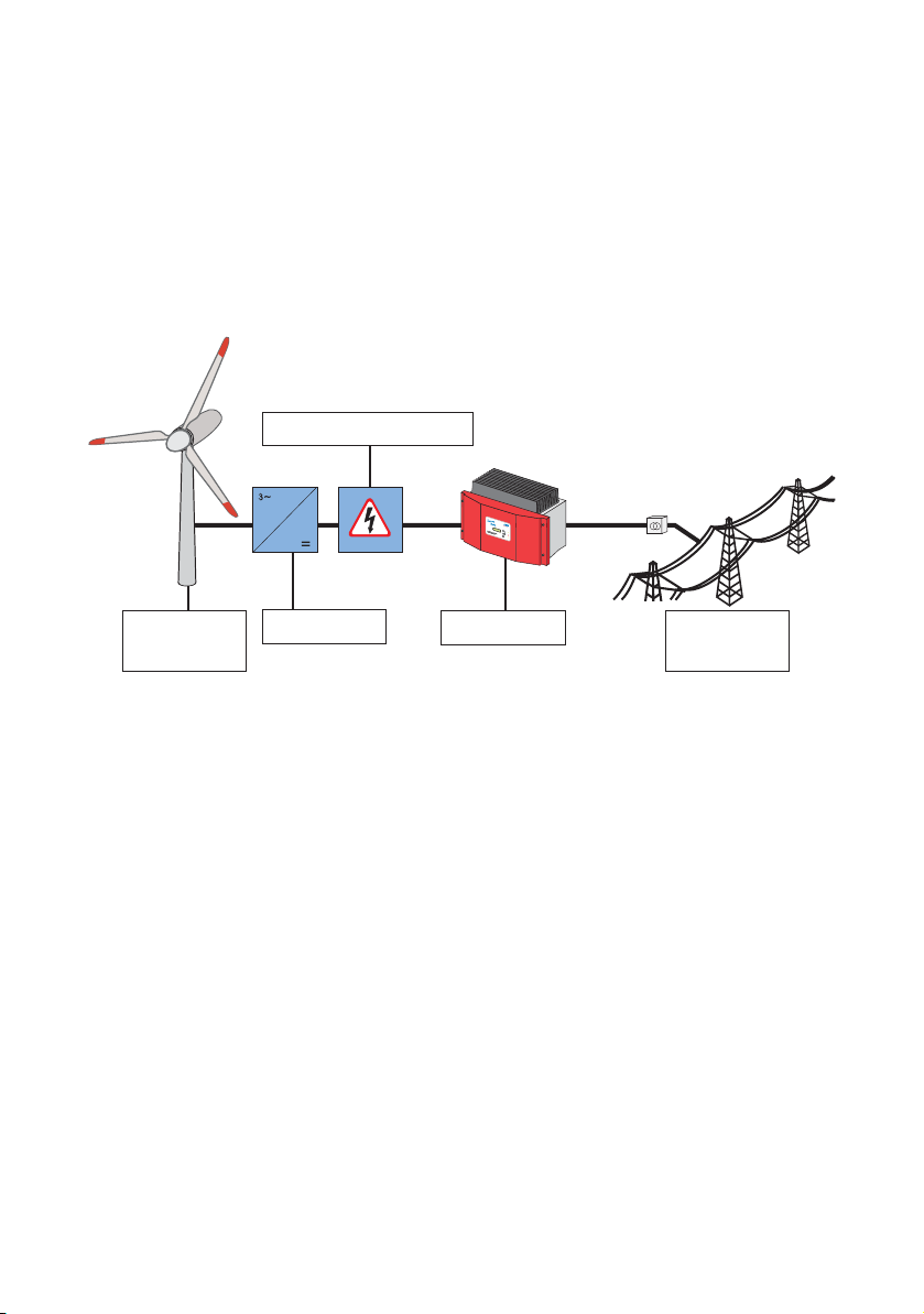
4.1 Appropriate Usage of the Windy Boy
The Windy Boy is designed for the conversion of rectified DC voltage from a wind
turbine (permanent magnet generator) into alternating current for feeding into the public
grid. The technical data is described in more detail in section 9 "Technical Data" (Page
51).
Overvoltage protection
Wind
turbine
Many wind turbine system manufacturers offer an extra overvoltage protection module.
This component prevents the destruction of the downstream Windy Boy in the event of
overvoltage.
Overvoltages can occur under the following conditions:
• High turbine rotation speeds under strong wind conditions.
• An increase in turbine rotation speed caused by load-shedding when the Windy
Boy is disconnected from the grid, e.g. in the event of grid faults or power outages.
The overvoltage protection system has the following tasks:
• When a pre-defined voltage is reached, the Windy Boy is disconnected from the
generator and a short-circuit slows the generator and/or brings it to a standstill.
• Some devices reduce the turbine rotation speed, and thus the generator output
voltage, by switching on a resistor (dumpload). The electrical energy generated
by the turbine is then converted to heat.
In grid-connected systems, we recommend the use of one of the electronic protection
mechanisms described here. Note that overvoltage at the Windy Boy can lead to
destruction of the device. In addition to this, you lose the right to all warranty claims even if the maximum input voltage of the Windy Boy is only exceeded for a short time.
User Manual WB1100LV-11:FE2606 Page 11
Rectifier Windy Boy
Public
grid

Unit Description SMA Technologie AG
The electronic protection system described here is always preferable to mechanical
solutions (pitch control, "turning out of the wind").
Any other use of the Windy Boy voids the warranty.
In the event of overvoltage, immediately disconnect the Windy Boy's DC
input! The presence of excessive input voltage can lead to irreparable
damage!
When the Windy Boy receives an excessive DC input voltage, it automatically
disconnects from the grid and ceases its power feeding activity. When the Windy
Boy is in operation, you must always first disconnect the AC voltage (grid voltage)
and only then should you disconnect the DC voltage from the Windy Boy!
Page 12 WB1100LV-11:FE2606 User Manual
SMA Technolog ie AG Unit Description
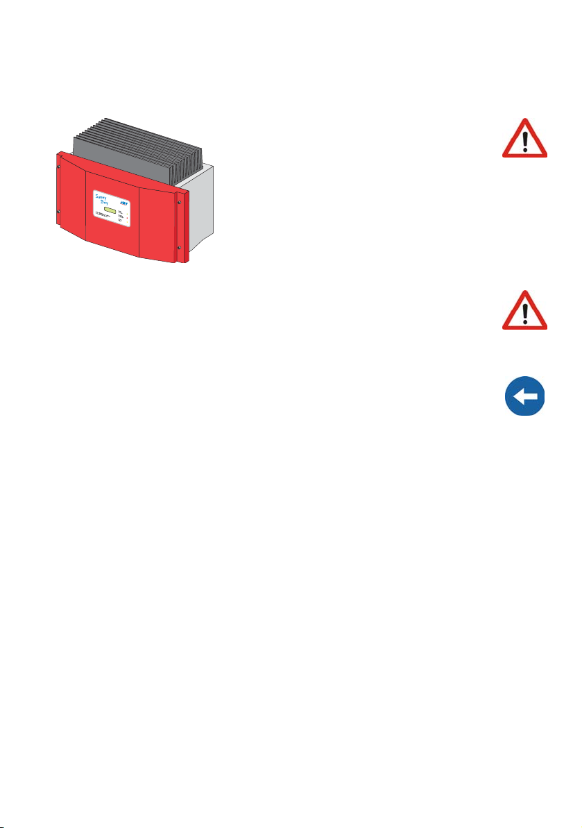
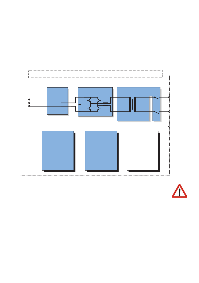
4.2 Structure of the Device
An attractive, functional design is one of the major design objectives of the entire Windy
Boy product range. In its basic configuration, the Windy Boy has the proven status
display consisting of three LEDs, as well as a plain text display.
As long as it is installed and commissioned according to the technical specifications, the
Windy Boy can be operated without any further modification or configuration. The
device parameters can however be modified, if required.
Windy Boy WB 1100LV housing IP65 (outdoor installation possible)
Wind
Bridge
SMA grid guard 2
curve
Transformer
N
DC input with terminal
PE
Overvoltage
protection:
thermally
monitored
varistors
Display
(IP65)
Optional
communication
interface:
RS232,
RS485,
Powerline,
radio
An extra communication interface is required for ideal adaptation of the
Windy Boy to suit the particular wind turbine being used, and this can also
be used for querying operational data. For further details, see section 8
"Extensions" (Page 43).
L
AC output with plug connector
User Manual WB1100LV-11:FE2606 Page 13
Unit Description SMA Technologie AG
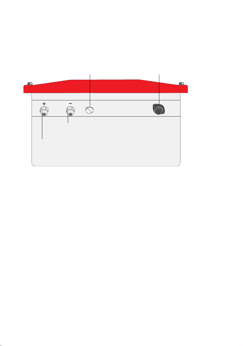
All DC connections and connections for the public grid, as well as any optional
communication connections are to be found on the underside of the Windy Boy. The
DC side is connected internally via screw terminals.
Openings for optional
communication via RS232,
RS485 or radio (PG16)
AC socket for
grid connection
Cable opening for DC -
Cable opening for DC +
Page 14 WB1100LV-11:FE2606 User Manual
SMA Technolog ie AG Unit Description
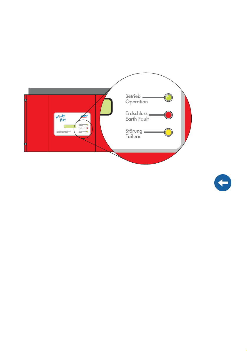
4.3 Operating Modes
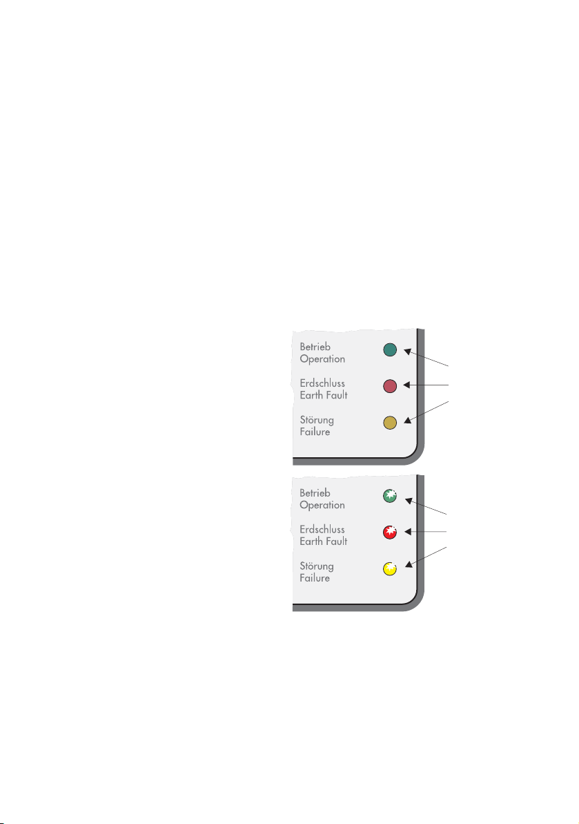
The various operating modes are displayed using three light-emitting diodes (LEDs) on
the housing cover of the Windy Boy. To allow the device to indicate its operating mode
via the integrated LEDs, the Windy Boy must be connected on the DC side. There must
be enough wind energy present, so that the Windy Boy has adequate DC voltage.
Especially in the first year of operation, the operator of the system should regularly
check this display under different wind speeds.
A complete description of the possible displays can be found in section 4.3.4
"Description of the Operating Modes" (Page 17). These can be split into three
categories:
4.3.1 Normal Operation
If no LED, or only the green control LED is on, or blinking, the inverter is operating
normally. The simultaneous illumination of all three LEDs is also an indication of normal
operation ("initialization"). All other displays are a sign of abnormal operation.
User Manual WB1100LV-11:FE2606 Page 15
Unit Description SMA Technologie AG
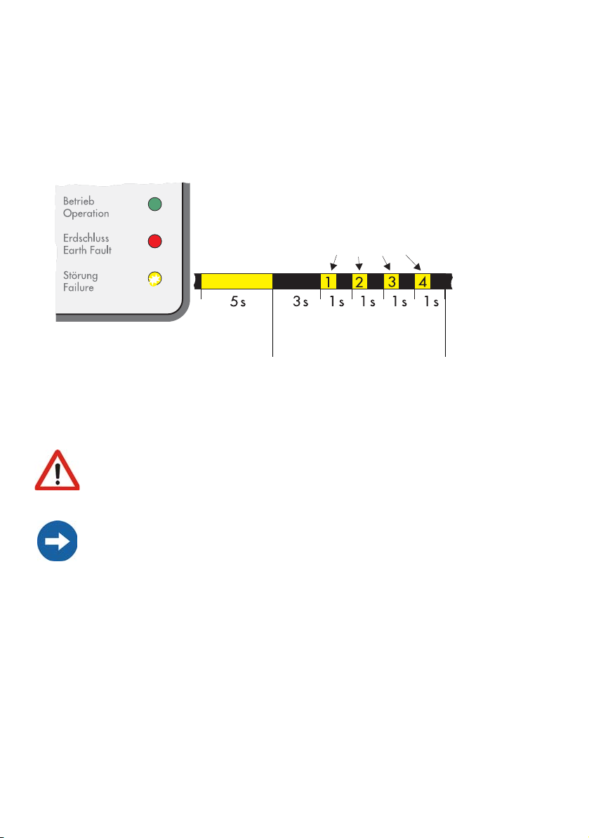
4.3.2 Critical Faulty Operation
A comprehensive safety concept has limited the number of critical conditions that can
occur to one single situation:
Input voltage exceeds the permitted value!
This is indicated by the following blink code on the yellow LED:
(green)
(red)
The yellow LED illuminates 4
times in quick succession
(yellow)
LED on
LED off
The code is repeated 3
times, then begins again.
The yellow fault LED illuminates for 5 seconds when this fault occurs, then begins
displaying the blink code of: 3 seconds off, then 4 times briefly on. This code is
displayed 3 times in succession. If the fault is still present, the fault display starts again
from the beginning.
The presence of excessive input voltage can lead to irreparable damage!
Immediately disconnect the Windy Boy's DC input.
When the Windy Boy receives an excessive DC input voltage, it automatically
disconnects from the grid and ceases its power feeding activity. When the Windy
Boy is in operation, you must always first disconnect the AC voltage (grid voltage)
and only then should you disconnect the DC voltage from the Windy Boy!
Page 16 WB1100LV-11:FE2606 User Manual
SMA Technolog ie AG Unit Description
4.3.3 Non-Critical Faulty Operation
All other display codes indicate some form of error condition, which is not usually
dangerous to people or equipment, but which should nevertheless be investigated and
corrected without delay.
Despite all precautions, it is possible that other errors may occur which cannot be
displayed (e.g. failure of the status display). In order to recognize such errors, the
operator of the system should use the explanations in section 4.3.4 "Description of the
Operating Modes" (Page 17) to check the plausibility of the displayed normal
operating modes.
Far more detailed diagnostics are possible using the communication options detailed in
section 8 "Extensions" (Page 43) .
4.3.4 Description of the Operating Modes
No (or Low) Input Voltage
The Windy Boy is in the so-called Standby
mode. This mode occurs when the input
power at the Windy Boy is too low for
feeding the grid and for satisfying the onboard power requirements.
All LEDs are
off.
Initialization
The Windy Boy's on-board computer is at
present in the initialization phase. Power
for the on-board power supply is present,
but output power is not yet sufficient for
grid feeding or for data transfer.
User Manual WB1100LV-11:FE2606 Page 17
All LEDs
are on.
Unit Description SMA Technologie AG
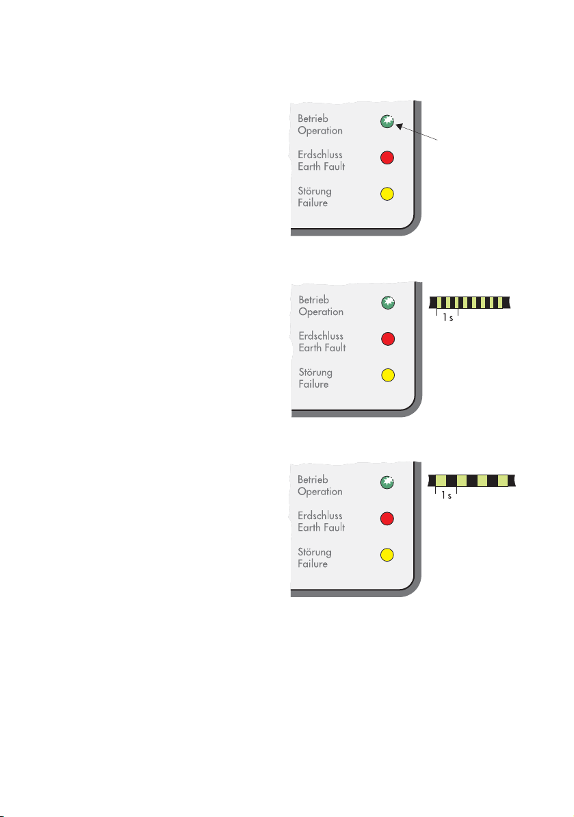
Working Mode
The Windy Boy has successfully passed
the measurement electronics and SMA
grid guard self-tests and has begun feedin operation.
The Windy Boy is working normally and is
feeding electricity into the grid. It
The green
LED is
illuminated.
processes the wind turbine system's DC
voltage according to the programmable
voltage/power curve (see section 6
"Turbine Operation" (Page 31)).
Stop
The Windy Boy is in Stop mode. Among
other functions, the measurement
electronics are calibrated, then the device
switches to "Waiting" mode.
The "Stop" mode can also be manually set
by the system operator via the Sunny Boy
Control or the Sunny Data PC program. In
The green LED
blinks 3 times
per second.
this case, the Windy Boy remains in
"Stop" mode until a new operating mode
(e.g. "Turbine mode") has been set.
Waiting, Grid Monitoring
The Windy Boy checks if the initial
conditions necessary for grid feeding are
satisfied (e.g. start voltage), then begins
monitoring the grid.
The green LED
blinks once per
second.
Page 18 WB1100LV-11:FE2606 User Manual

SMA Technolog ie AG Unit Description
Derating
The temperature monitoring of the Windy
Boy has reduced the output power to
prevent the device from overheating. If
this occurs often, this is an indication of
inadequate heat dissipation or excessive
input current.
• Temperature derating
The green LED
goes out briefly
once per
second.
To avoid unnecessary reductions in
yield, in this case it should be
checked if the Windy Boy can be
mounted in a more favorable
position with better ventilation.
• Current derating
The input current on the DC side exceeds the maximum possible input current. The
Windy Boy switches to the "Current Derating" mode in order to protect itself
against overload. Check the system layout.
Defective Varistor or Isolation Error
The red LED on the Windy Boy is
constantly on. A grounding error has
occurred, or one of the thermally
monitored varistors on the DC input side is
defective as a result of overvoltage.
not
relevant
The red
LED is
constantly on.
not
relevant
Consult a trained electrician to correct the fault using the installation
manual.
User Manual WB1100LV-11:FE2606 Page 19
Unit Description SMA Technologie AG
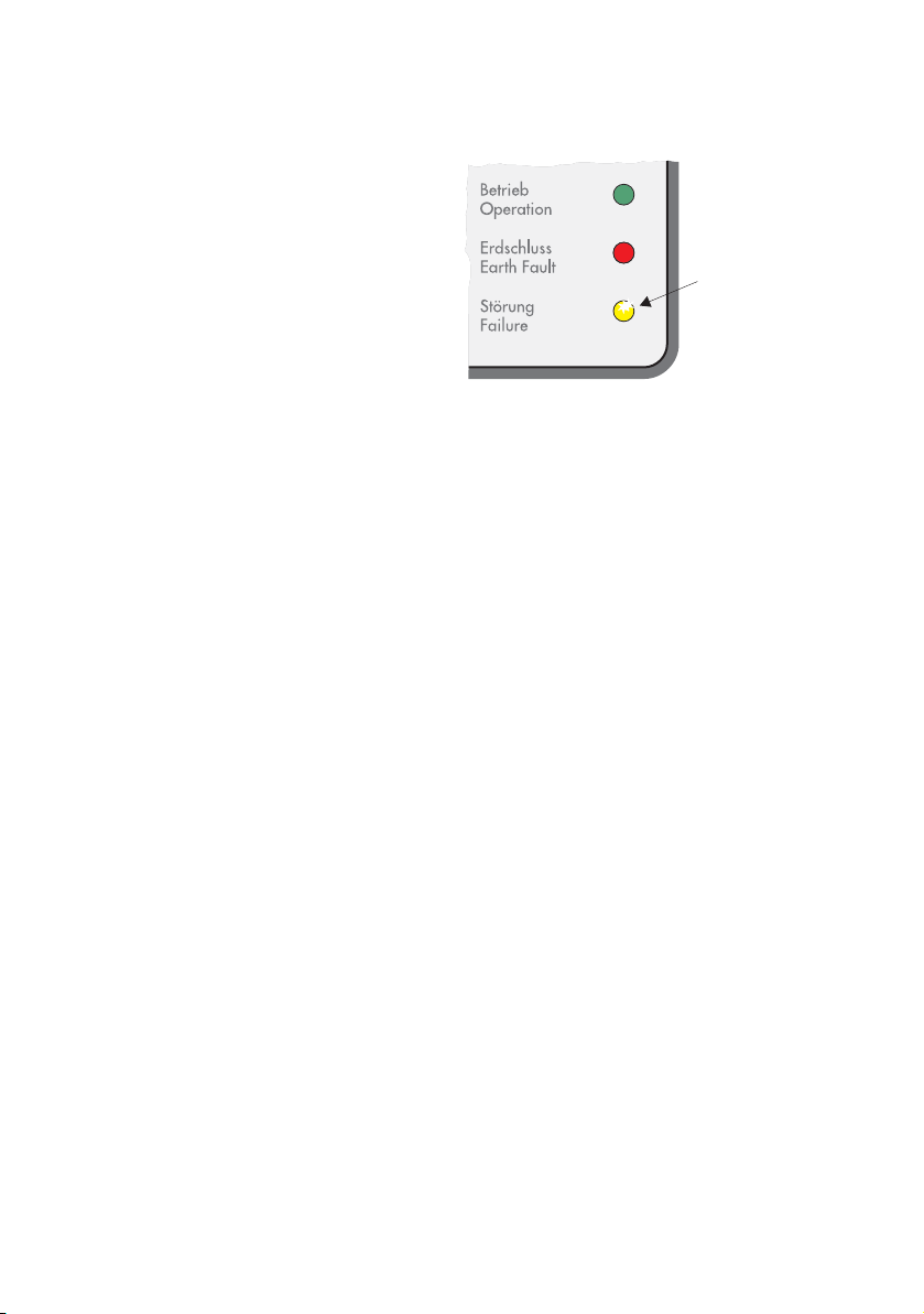
Permanent Disable
In the event of a recurring fault, the Windy
Boy switches to "Permanent Disable"
mode, and ceases grid feeding.
A fault may exist that cannot be resolved
on-site. You can attempt to correct the
error with the aid of a communication
interface and the corresponding
communication product (e.g. PC with
Sunny Data or Sunny Boy Control). If this
is unsuccessful, consult the Sunny Boy
hotline (section 12 "Contact" (Page 75))
to discuss further action to solve the
problem.
The yellow
LED is
constantly
on.
Page 20 WB1100LV-11:FE2606 User Manual
SMA Technolog ie AG Unit Description
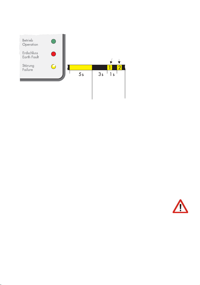
Grid Fault
(green)
(red)
The yellow LED illuminates
twice in quick succession.
(yellow)
LED on
LED off
The code is
repeated 3
times, then
begins again.
The yellow fault LED illuminates for 5 seconds when the fault occurs, and then begins
displaying the blink code of: 3 seconds off, then twice briefly on. This code is displayed
3 times in succession. If the fault is still present, the fault display starts again from the
beginning.
With this message, the Windy Boy indicates a grid fault, which can have the following
causes:
• Grid undervoltage (U
• Grid overvoltage (U
• Grid underfrequency (f
• Grid overfrequency (f
< "Uac-Min")
AC
> "Uac-Max")
AC
< "Fac-Min")
AC
> "Fac-Max")
AC
• Grid frequency change ("dFac").
Check if a general grid dropout has occurred (check the operation of other electrical
consumer devices), and check if the fuse of the Windy Boy's feed-in connection is intact.
If none of these faults can be found, then the Windy Boy's grid connection
must be checked by a qualified electrician.
User Manual WB1100LV-11:FE2606 Page 21
Unit Description SMA Technologie AG
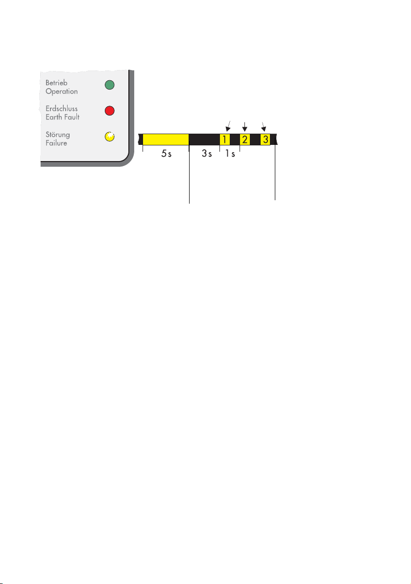
Excessive Grid Impedance
(green)
(red)
The yellow LED illuminates 3
times in quick succession.
(yellow)
LED on
LED off
The code is repeated
3 times, then begins
again.
The yellow fault LED illuminates for 5 seconds when the fault occurs, and then begins
displaying the blink code of: 3 seconds off, then 3 times briefly on. This code is
displayed 3 times in succession. If the fault is still present, the fault display starts again
from the beginning.
The Windy Boy has detected a fault relating to an unacceptable grid impedance. If the
Windy Boy frequently deactivates and displays this error during grid monitoring, the
cause can be an excessive grid impedance. A qualified electrician can usually assist
with this problem by increasing the cross-section of the grid connection cable. Other
measures can be taken to correct this fault, but they require the explicit agreement and
cooperation of the grid operator.
Page 22 WB1100LV-11:FE2606 User Manual
SMA Technolog ie AG Unit Description
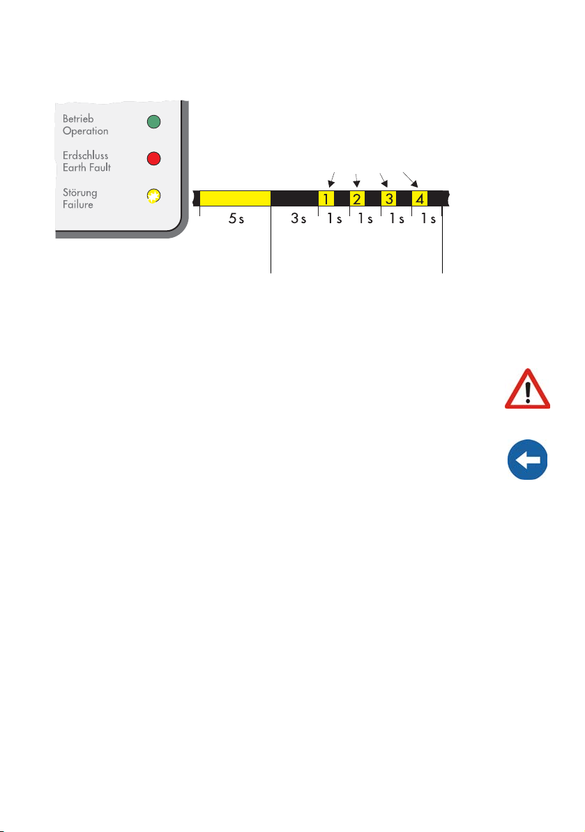
Excessive Input Voltage
(green)
(red)
The yellow LED illuminates 4
times in quick succession
(yellow)
LED on
LED off
The code is repeated 4
times, then begins again.
The yellow fault LED illuminates for 5 seconds when the fault occurs, then begins
displaying the blink code of: 3 seconds off, then 4 times briefly on. This code is
displayed 3 times in succession. If the fault is still present, the fault display starts again
from the beginning.
Immediately disconnect the Windy Boy's DC input. The presence of
excessive input voltage can lead to irreparable damage! Make sure that
the input voltage never exceeds 60 V.
When the Windy Boy receives an excessive DC input voltage, it automatically
disconnects from the grid and ceases its power feeding activity. When the Windy
Boy is in operation, you must always first disconnect the AC voltage (grid voltage)
and only then should you disconnect the DC voltage from the Windy Boy!
User Manual WB1100LV-11:FE2606 Page 23
Unit Description SMA Technologie AG
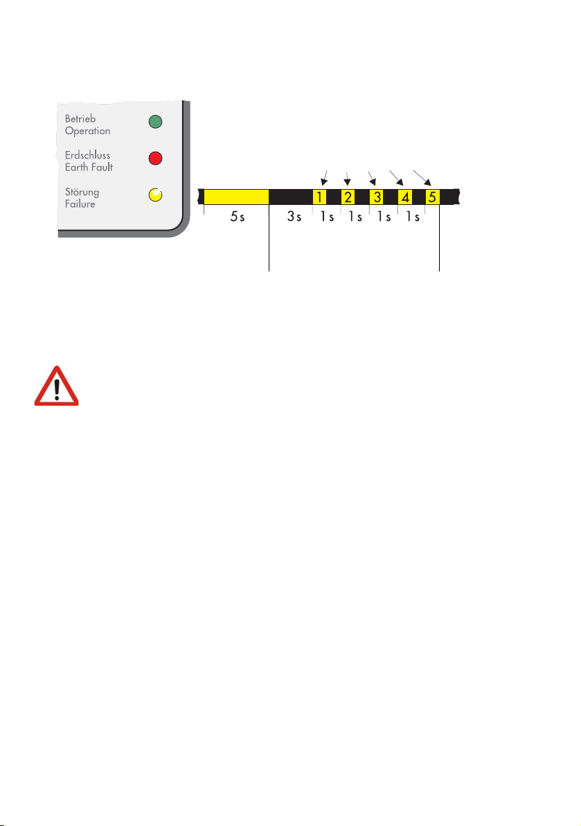
Device Fault
(green)
(red)
The yellow LED illuminates 5
times in quick succession
(yellow)
LED on
LED off
The code is repeated 5
times, then begins again.
The yellow fault LED illuminates for 5 seconds when the fault occurs, then begins
displaying the blink code of: 3 seconds off, then 5 times briefly on. This code is
displayed 3 times in succession. If the fault is still present, the fault display starts again
from the beginning.
If the device fault leads to a major impairment of normal operation, the
Windy Boy and the entire system installation should be checked by a
qualified electrician.
Page 24 WB1100LV-11:FE2606 User Manual
 Loading...