

Page 1
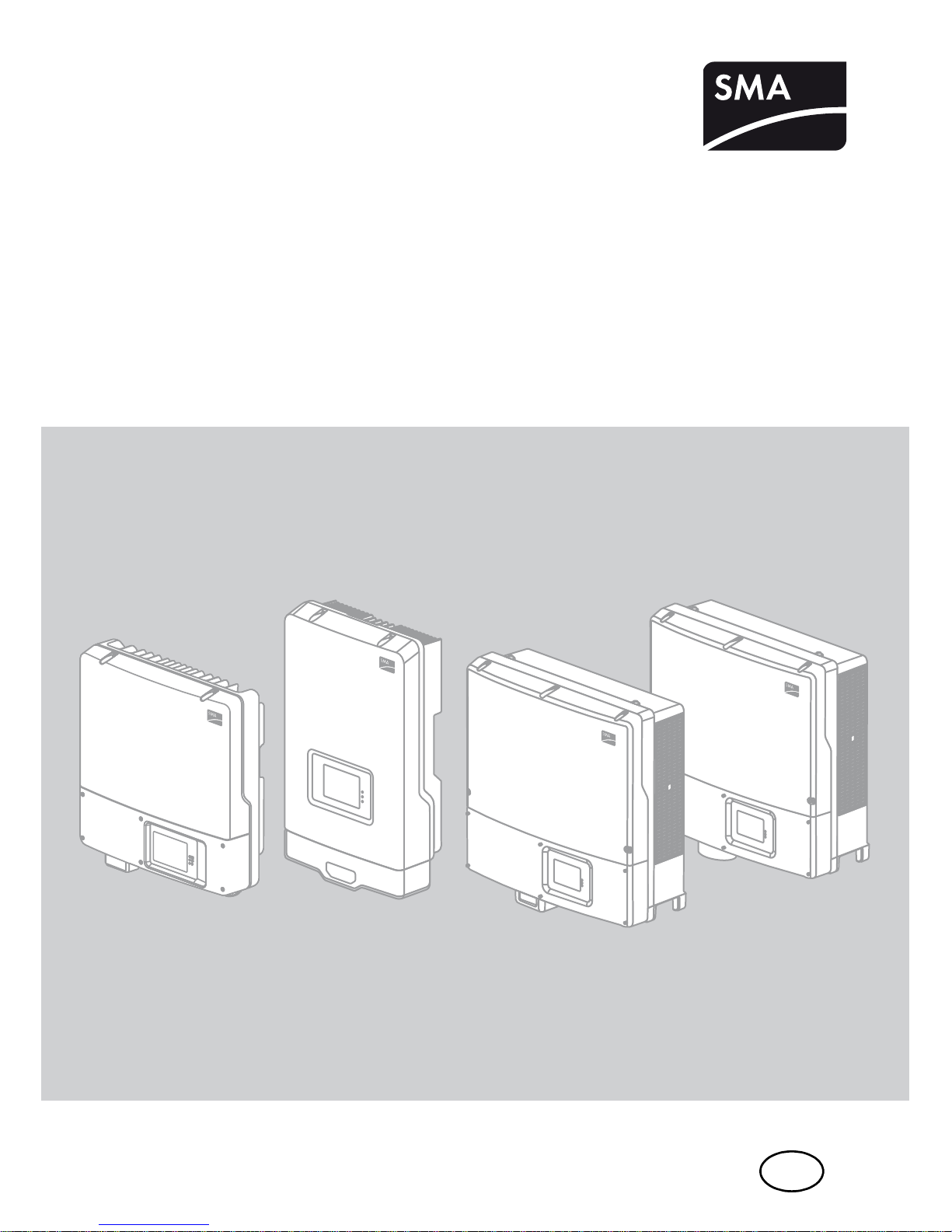
ZusFunktNG-TB-en-25 | Version 2.5
EN
Multi-Function Relay and OptiTrac Global Peak
SUNNYBOY/SUNNYTRIPOWER/WINDYBOY
Technical Description
Page 2

Page 3

SMA Solar Technology AG Table of Contents
Technical Description ZusFunktNG-TB-en-25 3
Table of Contents
1 Information on this Document. . . . . . . . . . . . . . . . . . . . . . . 5
1.1 Validity . . . . . . . . . . . . . . . . . . . . . . . . . . . . . . . . . . . . . . . . . . . . 5
1.2 Target Group . . . . . . . . . . . . . . . . . . . . . . . . . . . . . . . . . . . . . . . 6
1.3 Additional Information . . . . . . . . . . . . . . . . . . . . . . . . . . . . . . . . 6
1.4 Symbols Used . . . . . . . . . . . . . . . . . . . . . . . . . . . . . . . . . . . . . . . 6
2 Safety . . . . . . . . . . . . . . . . . . . . . . . . . . . . . . . . . . . . . . . . . . 7
2.1 Intended Use. . . . . . . . . . . . . . . . . . . . . . . . . . . . . . . . . . . . . . . . 7
2.2 Safety Precautions. . . . . . . . . . . . . . . . . . . . . . . . . . . . . . . . . . . . 7
3 Multifunction Relay . . . . . . . . . . . . . . . . . . . . . . . . . . . . . . . 8
3.1 Possible Applications of the Multifunction Relay. . . . . . . . . . . . . 8
3.2 Connection Options of the Multifunction Relay . . . . . . . . . . . . . 9
3.2.1 Connection as Fault Indicator Contact . . . . . . . . . . . . . . . . . . . . . . . . . . . . . 10
3.2.2 Connection for the Control of a Load . . . . . . . . . . . . . . . . . . . . . . . . . . . . . . 11
3.2.3 Connection for Grid Relay Switching Status . . . . . . . . . . . . . . . . . . . . . . . . . 12
3.3 Parameter Settings of the Multifunction Relay. . . . . . . . . . . . . . 13
3.3.1 Selecting the Operating Mode . . . . . . . . . . . . . . . . . . . . . . . . . . . . . . . . . . . 13
3.3.2 Operating Mode: Error Message . . . . . . . . . . . . . . . . . . . . . . . . . . . . . . . . . 14
3.3.3 Operating Mode: Self-Consumption . . . . . . . . . . . . . . . . . . . . . . . . . . . . . . . 14
3.3.4 Operating Mode: Fan Control . . . . . . . . . . . . . . . . . . . . . . . . . . . . . . . . . . . 15
3.3.5 Operating Mode: Control via Communication . . . . . . . . . . . . . . . . . . . . . . . 15
3.3.6 Operating Mode: Charging the Battery . . . . . . . . . . . . . . . . . . . . . . . . . . . . 16
3.3.7 Operating Mode: Switching Status Grid Relay. . . . . . . . . . . . . . . . . . . . . . . 16
3.4 Technical Data of the Multifunction Relay . . . . . . . . . . . . . . . . 17
4 OptiTrac Global Peak . . . . . . . . . . . . . . . . . . . . . . . . . . . . 18
4.1 Activating the OptiTrac Global Peak . . . . . . . . . . . . . . . . . . . . 18
4.2 Setting the OptiTrac Global Peak . . . . . . . . . . . . . . . . . . . . . . . 19
5 Contact . . . . . . . . . . . . . . . . . . . . . . . . . . . . . . . . . . . . . . . . 20
Page 4

Table of Contents SMA Solar Technology AG
4 ZusFunktNG-TB-en-25 Technical Description
Page 5

SMA Solar Technology AG Information on this Document
Technical Description ZusFunktNG-TB-en-25 5
1 Information on this Document
1.1 Validity
This document describes the connection options and operating modes of the multifunction relay and
the OptiTrac Global Peak function.
The multifunction relay and OptiTrac Global Peak are available in the following SMA inverters
depending on the hardware and firmware status.
● available
○ planned
■ retrofit option for the multifunction relay
▲ retrofit option for the multifunction relay via the RS485 Quick Module
− not available
Keep this document in a convenient place for future reference.
Inverter type Multifunction relay OptiTrac
Global Peak
Sunny Boy 2000HF (SB 2000HF-30) ▲ ●
Sunny Boy 2500HF (SB 2500HF-30) ▲ ●
Sunny Boy 3000HF (SB 3000HF-30) ▲ ●
SunnyBoy2500TLSingleTracker (SB2500TLST-21) ■ ○
SunnyBoy3000TLSingleTracker (SB3000TLST-21) ■ ○
Sunny Boy 3000TL (SB 3000TL-20/SB 3000TL-21) ● / ● ● / ○
Sunny Boy 3600TL (SB 3600TL-20/SB 3600TL-21) ● / ● ● / ○
Sunny Boy 4000TL (SB 4000TL-20/SB 4000TL-21) ● / ● ● / ○
Sunny Boy 5000TL (SB 5000TL-20/SB 5000TL-21) ● / ● ● / ○
Sunny Tripower 8000TL (STP 8000TL-10) ● ●
Sunny Tripower 10000TL (STP 10000TL-10) ● ●
Sunny Tripower 12000TL (STP 12000TL-10) ● ●
Sunny Tripower 15000TL (STP 15000TL-10) ● ●
Sunny Tripower 17000TL (STP 17000TL-10) ● ●
Sunny Tripower 15000TLEconomicExcellence
(STP 15000TLEE-10)
■
−
Sunny Tripower 15000TL High Efficiency
(STP 15000TLHE-10)
■
−
Sunny Tripower 20000TLEconomicExcellence
(STP 20000TLEE-10)
■
−
Sunny Tripower 20000TL High Efficiency
(STP 20000TLHE-10)
■
−
Windy Boy 3600TL (WB 3600TL-20) ● −
Windy Boy 5000TL (WB 5000TL-20) ● −
Page 6
Information on this Document SMA Solar Technology AG
6 ZusFunktNG-TB-en-25 Technical Description
1.2 Target Group
This document is intended for users and installers of the inverter. Some tasks described in this
document may only be carried out by electrically qualified persons.
1.3 Additional Information
Detailed information on the electrical connection of the multifunction relay in your inverter can be
found in the installation manual of the respective inverter or of the multifunction relay retrofit kit
MFR01-10. See the user manual for detailed information on how to operate the inverter.
You can find further information on special topics in the download area at www.SMA.de/en.
1.4 Symbols Used
The following types of safety precautions and general information appear in this document:
G
DANGER
DANGER indicates a hazardous situation which, if not avoided, results in death or serious
injury.
WARNING
WARNING indicates a hazardous situation which, if not avoided, can result in death or
serious injury.
CAUTION!
CAUTION indicates a hazardous situation which, if not avoided, can result in minor or
moderate injury.
NOTICE!
NOTICE indicates a situation which, if not avoided, can result in property damage.
Information
Information provides tips that are valuable for the optimal installation and operation of
your product.
Page 7
SMA Solar Technology AG Safety
Technical Description ZusFunktNG-TB-en-25 7
2 Safety
2.1 Intended Use
The multifunction relay is used for switching on and off a fault indicator or another external load based
on parameters and measured values of the inverter.
OptiTrac Global Peak is used for performance optimization in the event of partially shaded
PV modules.
Also observe the installation manual of the respective inverter.
2.2 Safety Precautions
DANGER
Danger to life due to high voltages in the inverter
• All work on the inverter must be carried out by an electrically qualified person only.
• Disconnect the inverter from both the DC and AC side as described in the installation
manual.
NOTICE!
Damage to the inverter due to electrostatic discharge
• Ground yourself before touching any components.
NOTICE!
Destruction of the multifunction relay due to too high contact load
• Adhere to the maximum switching voltage and maximum switching current
(see Section 3.4"Technical Data of the Multifunction Relay" (page17)).
• Only connect suitable contactors (see Section 3.2.2"Connection for the Control of
a Load" (page11)).
Page 8

Multifunction Relay SMA Solar Technology AG
8 ZusFunktNG-TB-en-25 Technical Description
3 Multifunction Relay
3.1 Possible Applications of the Multifunction Relay
The multifunction relay can be used for various purposes. The applications possibilities for the
multifunction relay depend on the firmware version. If the inverter has the suitable firmware, you can
select one of six operating modes to control the multifunction relay. All firmware versions support the
function as a fault indicator contact. If required, remaining functions can be retrofitted via a firmware
update.
Fault Indicator Contact
You can connect a display device to the multifunction relay, which either reports disturbances or
undisturbed operation of the inverter.
Optimization of Self-Consumption
In order to optimize self-consumption, loads can be switched on or off based on the power availability
of the PV array. The minimum duty cycle is configurable.
Activating Loads via Communication Devices
The multifunction relay allows you to activate and deactivate operational loads via the communication
interface of the inverter.
Power-Dependent Charging of Batteries
The multifunction relay allows you to control the charging of batteries based on the power availability
of the PV array.
Temperature-Dependent Activation of an External Fan
At high ambient temperatures, SMA inverters reduce their power to prevent overheating. If the
installation site does not meet the climate requirements specified in the inverter installation manual,
possible losses can be minimized through the use of additional cooling. For tailored cooling,
an external fan can be controlled via the multifunction relay based on the inverter temperature.
Reporting Start of Grid Feed-In to the Grid Operator
If required by the local grid operator, you can trip a signal to the grid operator via the multifunction
relay once the inverter connects to the utility grid. The multifunction relay simulates the switching status
of the grid relay.
Page 9
SMA Solar Technology AG Multifunction Relay
Technical Description ZusFunktNG-TB-en-25 9
3.2 Connection Options of the Multifunction Relay
The connections described in this section must only be made by electrically qualified persons.
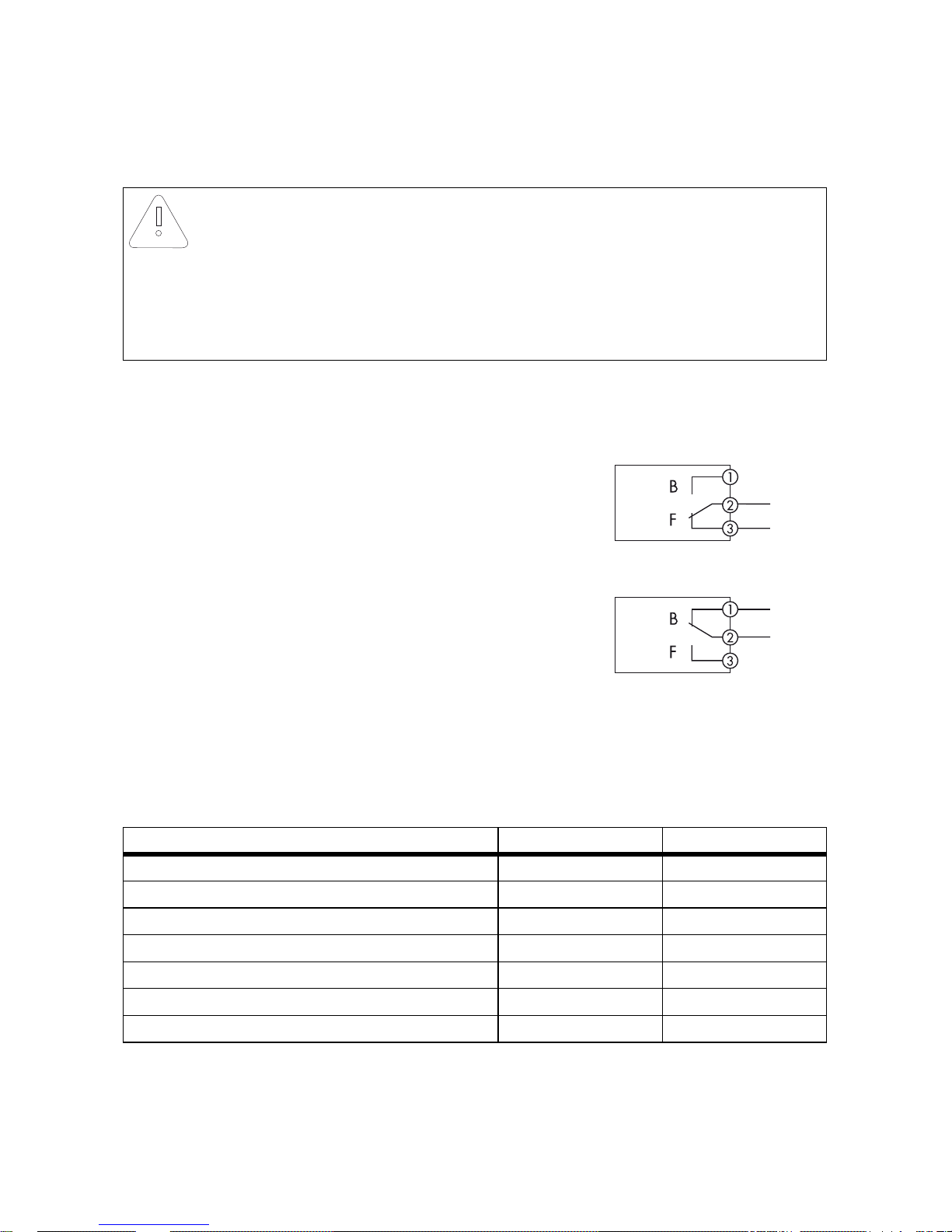
In the event of inverter voltage loss, the multifunction relay switches from the position 1-2
(Operation, B) to the position 2-3 (Error, F).
As a result of this relay switching behavior, there are two connection options:
• Use as fault indicator contact:
– The function to be switched is inactive in
relay position 1-2 (B)
– The function to be switched is active in
relay position 2-3 (F)
• Use for the switching of loads:
– The function to be switched is active in
relay position 1-2 (B)
– The function to be switched is inactive in
relay position 2-3 (F)
If you connect the multifunction relay to the utility grid, you must protect it with an individual circuit
breaker.
In the following table the various operating modes with the respective relay positions with active and
inactive function are listed.
NOTICE!
Destruction of the multifunction relay due to too high contact load
• Adhere to the maximum switching voltage and maximum switching current
(see Section 3.4"Technical Data of the Multifunction Relay" (page17)).
• Only connect suitable relays downstream (see Section 3.2.2"Connection for the
Control of a Load" (page11)).
Operating mode Function active Function inactive
Fault indicator contact, error message Position 2-3 Position 1-2
Fault indicator contact, operation message Position 1-2 Position 2-3
Power-dependent control of loads Position 1-2 Position 2-3
Control of an external fan Position 1-2 Position 2-3
Control via communication Position 1-2 Position 2-3
Power-dependent charging of batteries Position 1-2 Position 2-3
Report switching status of grid relay Position 1-2 Position 2-3
Page 10
Multifunction Relay SMA Solar Technology AG
10 ZusFunktNG-TB-en-25 Technical Description
3.2.1 Connection as Fault Indicator Contact
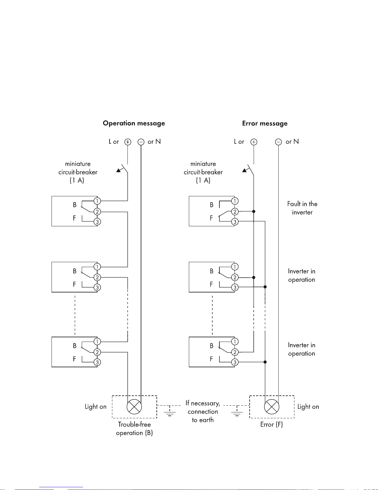
If you would like to operate a fault indicator, the relay must be connected so that position 2-3 is the
active position. You can also connect the multifunction relays of several inverters to one fault indicator.
The fault indicator displays as soon as one of the inverters shows an error.
If you would like to use the multifunction relay to indicate undisturbed operation, you must connect it
to all inverters in such a way that position 1-2 is the active position.
Page 11
SMA Solar Technology AG Multifunction Relay
Technical Description ZusFunktNG-TB-en-25 11
3.2.2 Connection for the Control of a Load
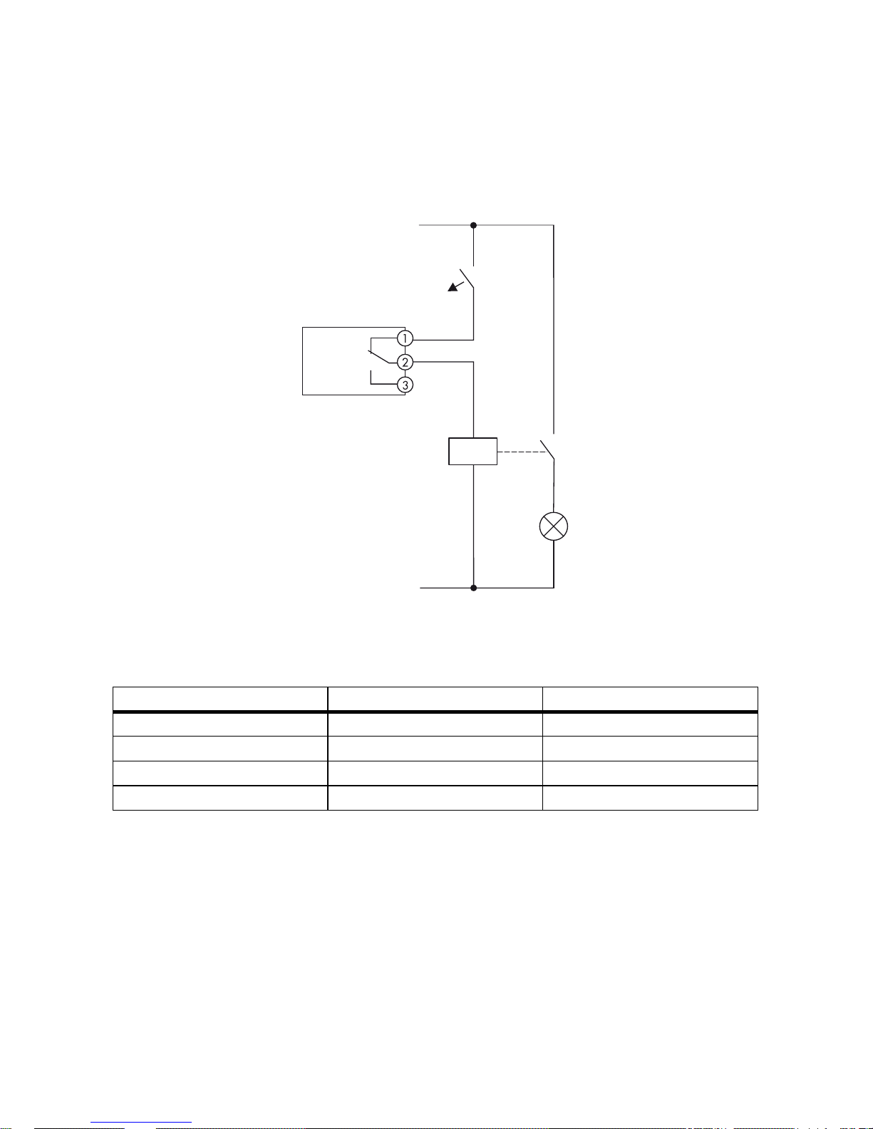
In most operating modes, a load is switched on and off based on parameters and measured values
of the inverter. For these operating modes, connect the multifunction relay so that it is active in position
1-2 (operation). It controls a contactor (K1), which switches the operating current for the load.
Between the multifunction relay and the loads, only use contactors which meet the connection
requirements of the multifunction relay (see Section 3.4"Technical Data of the Multifunction Relay"
(page17)). You will find some examples in the following table.
Manufacturer Model Coil
ABB TAL 9 to 40 series 230 V
Hager ES 2xx 230V
Siemens Insta contactor 5TT5 8xx-0 230V
Siemens Insta contactor 5TT5 80x-2 24 V
L
N
B
F
(1 A)
K1
miniature
circuit-breaker
Page 12
Multifunction Relay SMA Solar Technology AG
12 ZusFunktNG-TB-en-25 Technical Description
3.2.3 Connection for Grid Relay Switching Status
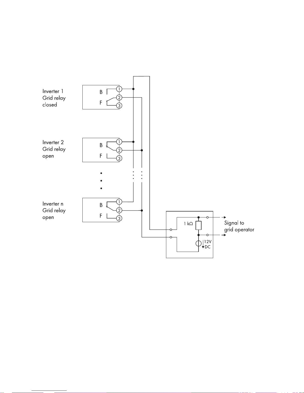
To send a signal to the grid operator once the first inverter connects to the utility grid, connect the
multifunction relays of all connected inverters in parallel. The figure below shows an example of this
type of connection.
Page 13

SMA Solar Technology AG Multifunction Relay
Technical Description ZusFunktNG-TB-en-25 13
3.3 Parameter Settings of the Multifunction Relay
3.3.1 Selecting the Operating Mode
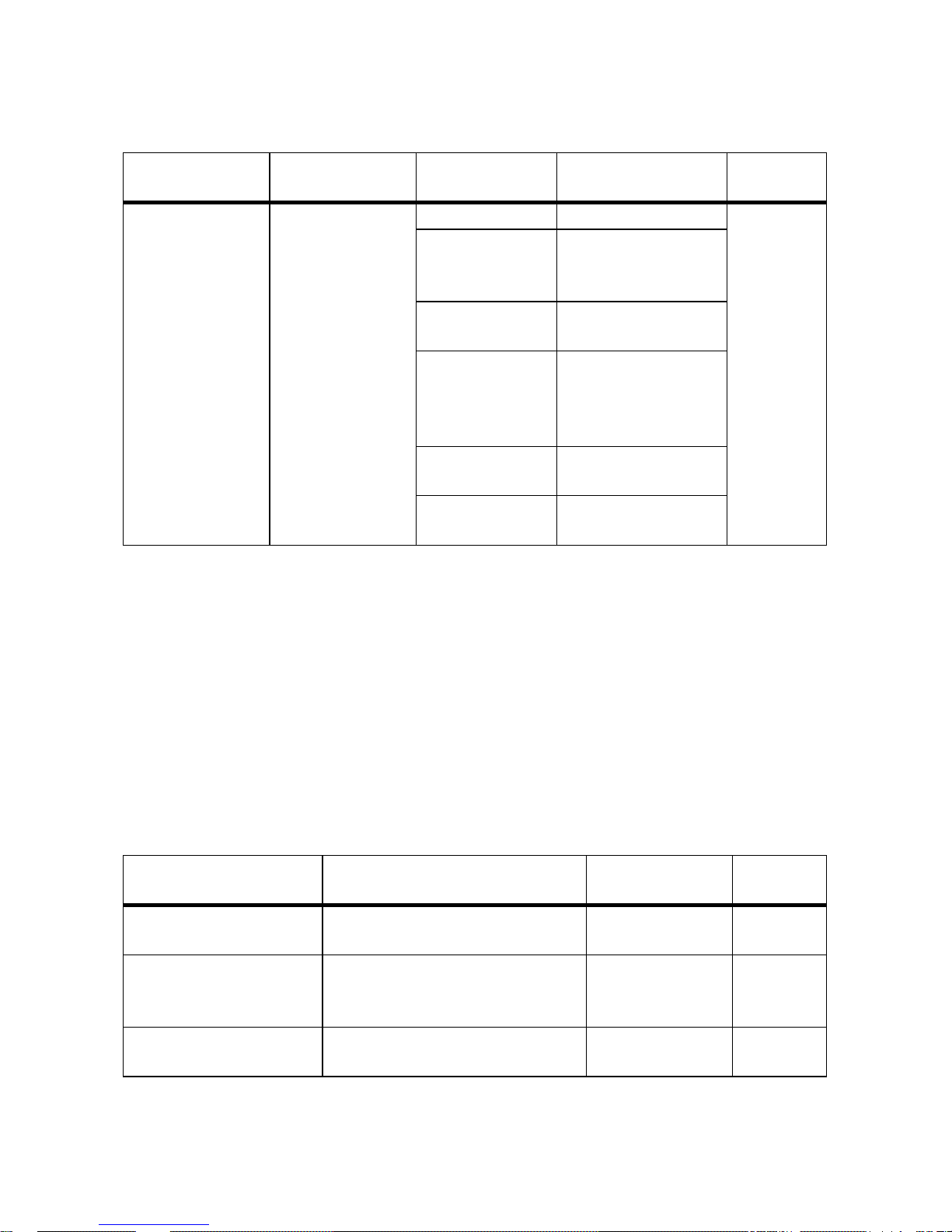
You configure the required operating mode and further settings via parameters. The following options
are available depending on the type of communication:
• Via RS485 with Sunny Data Control or Sunny WebBox
•Via Bluetooth
®
Wireless Technology with Sunny Explorer
Depending on the type of communication, the parameters are displayed differently on the
communication products.
Selecting the Operating Mode via RS485
Name Description Value Explanation Default
value
Mlt.OpMode Operating mode of
the multifunction
relay
FltInd Fault indicator contact FltInd
SelfCsmp Power-dependent
control of selfconsumption
FanCtl Control of an external
fan
ComCtl Control of external
loads via
communication
devices
BatCha Battery charging
GriSwCpy Display switching
status of the grid relay
Page 14
Multifunction Relay SMA Solar Technology AG
14 ZusFunktNG-TB-en-25 Technical Description
Selecting the Operating Mode via Bluetooth
3.3.2 Operating Mode: Error Message
To use the multifunction relay as fault indicator contact, you only need to select the operating mode
"FltInd" or "Fault indication". You determine whether the fault indicator displays errors or undisturbed
operation via the type of connection as described in Section 3.2.2"Connection for the Control of a
Load" (page11).
3.3.3 Operating Mode: Self-Consumption
In this operating mode the relay switches after a minimum time, in which the power was above a
certain limiting value. It then remains switched on for a configurable minimum duration.
Parameter Setting via RS485
Name Description Value Explanation Default
value
Operating mode of
the multifunction
relay
Operating mode of
the multifunction
relay
Error message Fault indicator contact Error
message
Self-consumption Power-dependent
control of selfconsumption
Fan control Control of an external
fan
Control via
communication
Control of external
loads via
communication
devices
Battery storage
system
Charging the battery
Switching status of
the grid relay
Display switching
status of the grid relay
Name Description Range Default
value
Mlt.MinOnPwr Minimum start-up power, tripping
level for self-consumption function
100 W to nominal
power
1,500 W
Mlt.MinOnPwrTmm Minimum time for which the minimum
start-up power must be fed in for the
relay to switch
0 min to 1,440 min 30 min
Mlt.MinOnTmm Minimum duration for which the
relay remains switched on
1 min to 1,440 min 120 min
Page 15

SMA Solar Technology AG Multifunction Relay
Technical Description ZusFunktNG-TB-en-25 15
Parameter Setting via Bluetooth
3.3.4 Operating Mode: Fan Control
In this operating mode, the fan is automatically activated if the device temperature is 5°C below the
temperature that trips derating. The fan is switched off again once the temperature falls 10°C below
the temperature limiting value. You do not need to set any parameters other than the operating mode.
3.3.5 Operating Mode: Control via Communication
In this operating mode you can switch the relay via the communication interface of the inverter.
Parameter Setting via RS485
Parameter Setting via Bluetooth
Name Description Range Default
value
Minimum On power for
MFR self-consumption
Minimum start-up power, tripping
level for self-consumption function
100 W to nominal
power
1,500 W
Minimum power On time,
MFR self-consumption
Minimum time for which the minimum
start-up power must be fed in for the
relay to switch
0 min to 1,440 min 30 min
Minimum On time for MFR
self-consumption
Minimum duration for which the
relay remains switched on
1 min to 1,440 min 120 min
Name Description Value Explanation Default
value
MltComCtl.Sw Status of the
multifunction relay in the
operating mode
"Control via
communication"
On Relay closed,
function active
Off
Off Relay open, function
inactive
Name Description Value Explanation Default
value
Status of the multifunction relay
with control via communication
Status of the
multifunction relay in the
operating mode
"Control via
communication"
On Relay closed,
function active
Off
Off Relay open, function
inactive
Page 16

Multifunction Relay SMA Solar Technology AG
16 ZusFunktNG-TB-en-25 Technical Description
3.3.6 Operating Mode: Charging the Battery
In this operating mode, the multifunction relay switches once a set minimum power is exceeded.
Upon falling below the set power, the relay switches off. It can then only be switched again after a
set minimum time.
Parameter Setting via RS485
Parameter Setting via Bluetooth
3.3.7 Operating Mode: Switching Status Grid Relay
In this operating mode, the multifunction relay switches simultaneously with the grid relay of the
inverter. You do not need to set any parameters other than the operating mode.
Name Description Range Default value
Mlt.BatCha.Pwr Limiting value for switching the
relay in operating mode 'Charge
battery'
100 W to
nominal power
1,500 W
Mlt.BatCha.Tmm Minimum time between switching
the relay off and back on
1min to
1,440 min
30 min
Name Description Range Default value
Minimum On power for MFR
battery bank
Limiting value for switching the
relay in operating mode 'Charge
battery'
100 W to
nominal
power
1,500 W
Minimum time before
reconnection of MFR battery
bank
Minimum time between switching
the relay off and back on
1min to
1,440 min
30 min
Page 17
SMA Solar Technology AG Multifunction Relay
Technical Description ZusFunktNG-TB-en-25 17
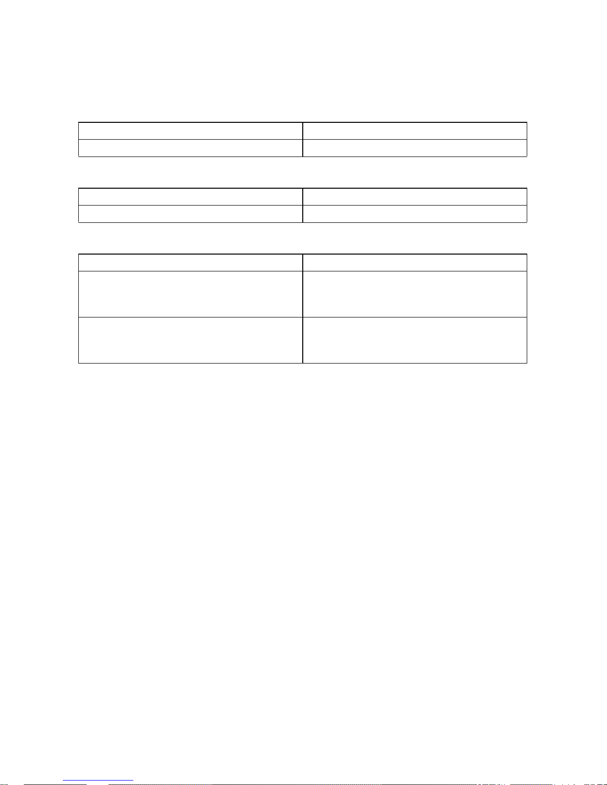
3.4 Technical Data of the Multifunction Relay
Maximum Switching Voltage
Maximum Switching Current
General
*equates to 20 years at twelve switching operations per day
AC 240 V
DC 30 V
AC 1.0 A
DC 1.0 A
Terminal Three-pole spring-cage terminal
Terminal on RS485 Quick Module
(only for SB 2000HF-30/SB 2500HF-30/
SB 3000HF-30)
Three-pole screw terminal
Electrical endurance (when adhering to the
maximum switching voltage and maximum
switching current)
at least 100,000 switching cycles*
Page 18

OptiTrac Global Peak SMA Solar Technology AG
18 ZusFunktNG-TB-en-25 Technical Description
4 OptiTrac Global Peak
OptiTrac Global Peak is an extension of the proven OptiTrac yield optimization function.
OptiTrac Global Peak improves the yield of the PV system for partially shaded PV modules. For further
information on this topic, refer to the Technical Information "Shade Management" available in the
download area at www.SMA.de/en.
4.1 Activating the OptiTrac Global Peak
OptiTrac Global Peak is deactivated upon delivery. Only activate this function if the PV system is
shaded in order to increase the yield. The following options are available depending on the type of
communication:
• Via RS485 with Sunny Data Control or Sunny WebBox
•Via Bluetooth with Sunny Explorer or Sunny WebBox with Bluetooth
Depending on the type of communication, the parameters are displayed differently on the
communication products.
Parameter Setting via RS485
Parameter Setting via Bluetooth
Name Description Value Explanation Default value
MPPShdw.IsOn Activation or
deactivation of
OptiTrac Global Peak
On Function active Off
Off Function inactive
Name Description Value Explanation Default value
OptiTrac Global Peak
switched on
Activation or
deactivation of
OptiTrac Global Peak
Ein Function active Aus
Aus Function inactive
Page 19
SMA Solar Technology AG OptiTrac Global Peak
Technical Description ZusFunktNG-TB-en-25 19
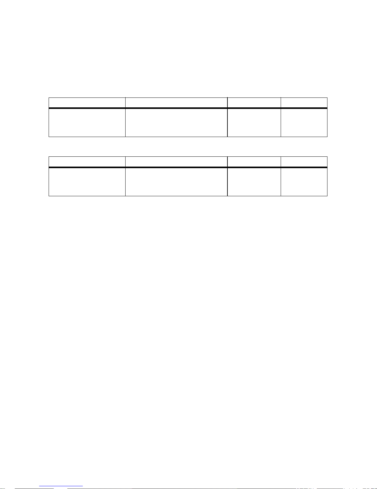
4.2 Setting the OptiTrac Global Peak
Upon logging in as an installer, you can also configure the functions of OptiTrac Global Peak.
You can specify the interval between two analyses of the operating point of the PV array.
Parameter Setting via RS485
Parameter Setting via Bluetooth
Name Description Range Default value
MPPShdw.CycTms Interval in which the inverter
optimizes the operating point of the
PV system
6min to 30min 6min
Name Description Range Default value
Cycle time of the
OptiTrac Global Peak
algorithm
Interval in which the inverter
optimizes the operating point of the
PV system
6min to 30min 6min
Page 20

Contact SMA Solar Technology AG
20 ZusFunktNG-TB-en-25 Technical Description
5 Contact
If you have technical problems concerning our products, contact the SMA Service Line.
We require the following information in order to provide you with the necessary assistance:
•Inverter device type
• Inverter serial number
• Inverter firmware version
• Special country-specific settings of the inverter (if applicable)
• Type and number of PV modules connected
• Mounting location and mounting altitude of the inverter
• Three-digit or four-digit event number and display message of the inverter
• Optional equipment, e.g. communication products
• Type of use of the multifunction relay/fault indicator contact (if present)
SMA Solar Technology AG
Sonnenallee 1
34266 Niestetal, Germany
www.SMA.de
SMA Service Line
Inverters: +49 561 9522 1499
Communication: +49 561 9522 2499
SMS with "CALL BACK" to: +49 176 888 222 44
Fax: +49 561 9522 4699
E-mail: [email protected]
Page 21

SMA Solar Technology AG Legal Restrictions
Technical Description ZusFunktNG-TB-en-25 21
The information contained in this document is the property of SMA Solar Technology AG. Publishing its content, either partially
or in full, requires the written permission of SMA Solar Technology AG. Any internal company copying of the document for the
purposes of evaluating the product or its correct implementation is allowed and does not require permission.
SMA Factory Warranty
The current warranty conditions come enclosed with your device. These are also available online at www.SMA.de and can be
downloaded and are available on paper from the usual sales channels if required.
Trademarks
All trademarks are recognized even if these are not marked separately. Missing designations do not mean that a product or brand
is not a registered trademark.
The Bluetooth
®
word mark and logos are registered trademarks owned by Bluetooth SIG, Inc. and any use of such marks by
SMA Solar Technology AG is under license.
SMA Solar Technology AG
Sonnenallee 1
34266 Niestetal
Germany
Tel. +49 561 9522-0
Fax +49 561 9522-100
www.SMA.de
E-Mail: [email protected]
© 2004 to 2013 SMA Solar Technology AG. All rights reserved
Page 22

XXX4."4PMBSDPN
4."4PMBS5FDIOPMPHZ
4."4PMBS5FDIOPMPHZ"(
XXX4."EF
4.""NFSJDB--$
XXX4.""NFSJDBDPN
4."5FDIOPMPHZ"VTUSBMJB1UZ-UE
XXX4.""VTUSBMJBDPNBV
4."#FOFMVY413-
XXX4."#FOFMVYDPN
4."#FJKJOH$PNNFSDJBM$P-UE
XXX4."$IJOBDPN
4."$[FDI3FQVCMJDTSP
XXX4."$[FDIDPN
4."'SBODF4"4
XXX4."'SBODFDPN
4.")FMMBT"&
XXX4.")FMMBTDPN
4."*C©SJDB5FDOPMPHB4PMBS4-
XXX4."*CFSJDBDPN
4."*UBMJB4SM
XXX4."*UBMJBDPN
4."5FDIOPMPHZ,PSFB$P-UE
XXX4.",PSFBDPN
 Loading...