

Page 1
EN
Wind Power Inverter
WINDY BOY 5000A / 6000A
Installation Manual
WB5A_6A-IA-IEN114540 | IME-WB50A_60A | Version 4.0
Page 2

Page 3

SMA Solar Technology AG Table of Contents
Table of Contents
1 Information on this Manual. . . . . . . . . . . . . . . . . . . . . . . . . 7
1.1 Validity . . . . . . . . . . . . . . . . . . . . . . . . . . . . . . . . . . . . . . . . . . . . 7
1.2 Target Group . . . . . . . . . . . . . . . . . . . . . . . . . . . . . . . . . . . . . . . 7
1.3 Additional Information . . . . . . . . . . . . . . . . . . . . . . . . . . . . . . . . 7
1.4 Symbols Used . . . . . . . . . . . . . . . . . . . . . . . . . . . . . . . . . . . . . . . 8
2 Safety . . . . . . . . . . . . . . . . . . . . . . . . . . . . . . . . . . . . . . . . . . 9
2.1 Intended Use. . . . . . . . . . . . . . . . . . . . . . . . . . . . . . . . . . . . . . . . 9
2.2 Safety Precautions. . . . . . . . . . . . . . . . . . . . . . . . . . . . . . . . . . . 10
2.3 Explanation of Symbols . . . . . . . . . . . . . . . . . . . . . . . . . . . . . . 11
2.3.1 Symbols on the Inverter. . . . . . . . . . . . . . . . . . . . . . . . . . . . . . . . . . . . . . . . . 11
2.3.2 Symbols on the Type Label . . . . . . . . . . . . . . . . . . . . . . . . . . . . . . . . . . . . . . 12
3 Unpacking. . . . . . . . . . . . . . . . . . . . . . . . . . . . . . . . . . . . . . 13
3.1 Scope of Delivery . . . . . . . . . . . . . . . . . . . . . . . . . . . . . . . . . . . 13
3.2 Identifying the Inverter . . . . . . . . . . . . . . . . . . . . . . . . . . . . . . . 14
4 Mounting. . . . . . . . . . . . . . . . . . . . . . . . . . . . . . . . . . . . . . . 15
4.1 Safety . . . . . . . . . . . . . . . . . . . . . . . . . . . . . . . . . . . . . . . . . . . . 15
4.2 Selecting the Mounting Location. . . . . . . . . . . . . . . . . . . . . . . . 16
4.3 Mounting the Inverter with the Wall Mounting Bracket . . . . . . 18
5 Electrical Connection . . . . . . . . . . . . . . . . . . . . . . . . . . . . . 21
5.1 Overview of the Connection Area . . . . . . . . . . . . . . . . . . . . . . 21
5.1.1 Exterior View . . . . . . . . . . . . . . . . . . . . . . . . . . . . . . . . . . . . . . . . . . . . . . . . . 21
5.1.2 Interior View . . . . . . . . . . . . . . . . . . . . . . . . . . . . . . . . . . . . . . . . . . . . . . . . . 22
5.2 Connection to the Power Distribution Grid (AC). . . . . . . . . . . . 24
5.2.1 Conditions for AC Connection . . . . . . . . . . . . . . . . . . . . . . . . . . . . . . . . . . . 24
5.2.2 Connecting the Inverter to the Power Distribution Grid (AC) . . . . . . . . . . . . 26
5.2.3 Additional Grounding of the Enclosure. . . . . . . . . . . . . . . . . . . . . . . . . . . . . 28
Installation Manual WB5A_6A-IA-IEN114540 3
Page 4

Table of Contents SMA Solar Technology AG
5.3 Setting the Display Language . . . . . . . . . . . . . . . . . . . . . . . . . . 29
5.4 Connecting the Small Wind Turbine System (DC) . . . . . . . . . . 30
5.4.1 Conditions for the DC Connection . . . . . . . . . . . . . . . . . . . . . . . . . . . . . . . . 30
5.4.2 Assembling the DC Connectors. . . . . . . . . . . . . . . . . . . . . . . . . . . . . . . . . . . 31
5.4.3 Opening the DC Connector . . . . . . . . . . . . . . . . . . . . . . . . . . . . . . . . . . . . . 33
5.4.4 Connecting the Small Wind Turbine System (DC). . . . . . . . . . . . . . . . . . . . . 34
5.5 Connection of the SMA Power Balancer . . . . . . . . . . . . . . . . . 36
5.5.1 Configuration . . . . . . . . . . . . . . . . . . . . . . . . . . . . . . . . . . . . . . . . . . . . . . . . 36
5.5.2 Cabling . . . . . . . . . . . . . . . . . . . . . . . . . . . . . . . . . . . . . . . . . . . . . . . . . . . . . 40
5.5.3 Function Test . . . . . . . . . . . . . . . . . . . . . . . . . . . . . . . . . . . . . . . . . . . . . . . . . 44
5.6 Communication. . . . . . . . . . . . . . . . . . . . . . . . . . . . . . . . . . . . . 45
5.7 Setting the Grid and Country Parameters . . . . . . . . . . . . . . . . . 45
5.7.1 Setting the Country of Installation . . . . . . . . . . . . . . . . . . . . . . . . . . . . . . . . . 45
5.7.2 Setting Off-Grid Operation . . . . . . . . . . . . . . . . . . . . . . . . . . . . . . . . . . . . . . 46
5.8 Polynomial Curve . . . . . . . . . . . . . . . . . . . . . . . . . . . . . . . . . . . 47
6 Commissioning . . . . . . . . . . . . . . . . . . . . . . . . . . . . . . . . . . 48
6.1 Commissioning the Inverter. . . . . . . . . . . . . . . . . . . . . . . . . . . . 48
6.2 Display Messages in the Startup Phase . . . . . . . . . . . . . . . . . . 49
6.3 Self-test in Accordance with DK 5940, Ed. 2.2
(Applies to Italy Only). . . . . . . . . . . . . . . . . . . . . . . . . . . . . . . . 50
6.3.1 Starting the Self-Test by Tapping. . . . . . . . . . . . . . . . . . . . . . . . . . . . . . . . . . 50
6.3.2 Completion of the Self-test. . . . . . . . . . . . . . . . . . . . . . . . . . . . . . . . . . . . . . . 51
6.4 Operating States of the Inverter . . . . . . . . . . . . . . . . . . . . . . . . 55
7 Opening and Closing. . . . . . . . . . . . . . . . . . . . . . . . . . . . . 56
7.1 Safety . . . . . . . . . . . . . . . . . . . . . . . . . . . . . . . . . . . . . . . . . . . . 56
7.2 Opening the Inverter. . . . . . . . . . . . . . . . . . . . . . . . . . . . . . . . . 57
7.3 Closing the Inverter. . . . . . . . . . . . . . . . . . . . . . . . . . . . . . . . . . 59
4 WB5A_6A-IA-IEN114540 Installation Manual
Page 5

SMA Solar Technology AG Table of Contents
8 Maintenance and Cleaning. . . . . . . . . . . . . . . . . . . . . . . . 61
8.1 Cleaning the Inverter. . . . . . . . . . . . . . . . . . . . . . . . . . . . . . . . . 61
8.2 Checking the Heat Dissipation . . . . . . . . . . . . . . . . . . . . . . . . . 61
8.2.1 Cleaning the Fans . . . . . . . . . . . . . . . . . . . . . . . . . . . . . . . . . . . . . . . . . . . . . 61
8.2.2 Checking the Fan . . . . . . . . . . . . . . . . . . . . . . . . . . . . . . . . . . . . . . . . . . . . . 63
8.3 Cleaning the Ventilation Grids . . . . . . . . . . . . . . . . . . . . . . . . . 64
9 Troubleshooting . . . . . . . . . . . . . . . . . . . . . . . . . . . . . . . . . 65
9.1 Blink Codes. . . . . . . . . . . . . . . . . . . . . . . . . . . . . . . . . . . . . . . . 65
9.2 Error Messages. . . . . . . . . . . . . . . . . . . . . . . . . . . . . . . . . . . . . 66
9.3 Red LED Permanently On . . . . . . . . . . . . . . . . . . . . . . . . . . . . . 71
9.3.1 Checking the Small Wind Turbine System for a Ground Fault . . . . . . . . . . . 71
9.3.2 Checking the Function of the Varistors . . . . . . . . . . . . . . . . . . . . . . . . . . . . . 72
10 Decommissioning . . . . . . . . . . . . . . . . . . . . . . . . . . . . . . . . 74
10.1 Disassembling the Inverter . . . . . . . . . . . . . . . . . . . . . . . . . . . . 74
10.2 Packing the Inverter. . . . . . . . . . . . . . . . . . . . . . . . . . . . . . . . . . 75
10.3 Storing the Inverter . . . . . . . . . . . . . . . . . . . . . . . . . . . . . . . . . . 75
10.4 Disposing of the Inverter . . . . . . . . . . . . . . . . . . . . . . . . . . . . . . 75
11 Technical Data . . . . . . . . . . . . . . . . . . . . . . . . . . . . . . . . . . 76
11.1 DC/AC . . . . . . . . . . . . . . . . . . . . . . . . . . . . . . . . . . . . . . . . . . . 76
11.1.1 Windy Boy 5000A . . . . . . . . . . . . . . . . . . . . . . . . . . . . . . . . . . . . . . . . . . . . 76
11.1.2 Windy Boy 6000A . . . . . . . . . . . . . . . . . . . . . . . . . . . . . . . . . . . . . . . . . . . . 78
11.2 General Data . . . . . . . . . . . . . . . . . . . . . . . . . . . . . . . . . . . . . . 80
11.3 Protective devices . . . . . . . . . . . . . . . . . . . . . . . . . . . . . . . . . . . 80
11.4 National Standards . . . . . . . . . . . . . . . . . . . . . . . . . . . . . . . . . 81
11.5 Climatic Conditions. . . . . . . . . . . . . . . . . . . . . . . . . . . . . . . . . . 81
11.6 Features . . . . . . . . . . . . . . . . . . . . . . . . . . . . . . . . . . . . . . . . . . 82
11.7 Torque. . . . . . . . . . . . . . . . . . . . . . . . . . . . . . . . . . . . . . . . . . . . 82
11.8 Distribution Systems . . . . . . . . . . . . . . . . . . . . . . . . . . . . . . . . . 82
Installation Manual WB5A_6A-IA-IEN114540 5
Page 6

Table of Contents SMA Solar Technology AG
12 Accessories . . . . . . . . . . . . . . . . . . . . . . . . . . . . . . . . . . . . . 83
13 Contact . . . . . . . . . . . . . . . . . . . . . . . . . . . . . . . . . . . . . . . . 84
6 WB5A_6A-IA-IEN114540 Installation Manual
Page 7

SMA Solar Technology AG Information on this Manual
1 Information on this Manual
1.1 Validity
This manual describes the mounting, installation, commissioning and maintenance of the following
SMA inverters:
• Windy Boy 5000A (WB 5000A, WB 5000A-11, WB 5000A-IT)
• Windy Boy 6000A (WB 6000A, WB 6000A-11, WB 6000A-IT)
Keep this manual in a convenient place for future reference.
1.2 Target Group
This manual is intended for electrically qualified persons. The tasks described in this manual may be
performed by electrically qualified persons only.
1.3 Additional Information
You will find further information on special topics such as designing a miniature circuit-breaker or the
description of the operating parameters in the download area at www.SMA.de/en.
Refer to the user manual provided for detailed information on operating the inverter.
Installation Manual WB5A_6A-IA-IEN114540 7
Page 8
Information on this Manual SMA Solar Technology AG
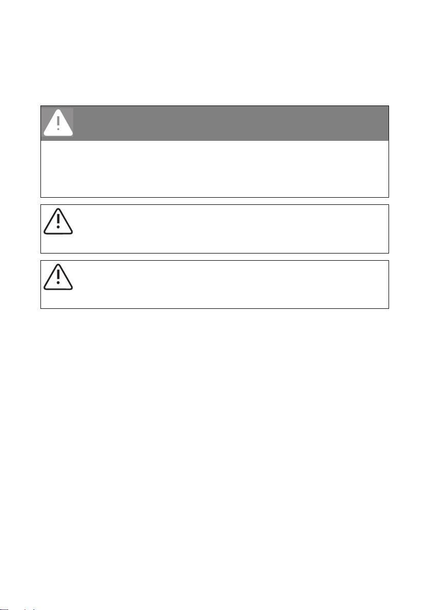
1.4 Symbols Used
The following types of safety precautions and general information are used in this manual:
DANGER!
DANGER indicates a hazardous situation which, if not avoided, will directly result in death
or serious injury.
WARNING!
WARNING indicates a hazardous situation which, if not avoided, can result in death or
serious injury.
CAUTION!
CAUTION indicates a hazardous situation which, if not avoided, could result in minor or
moderate injury.
NOTICE!
NOTICE indicates a situation that can result in property damage if not avoided.
Information
Information provides tips that are valuable for the optimal installation and operation of the
product.
☑ This symbol indicates the result of an action.
8 WB5A_6A-IA-IEN114540 Installation Manual
Page 9
SMA Solar Technology AG Safety
2 Safety
2.1 Intended Use
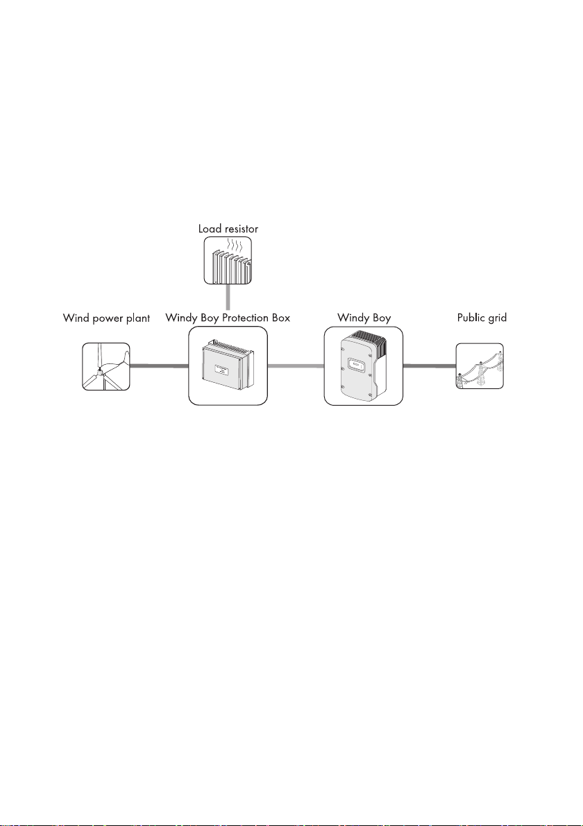
The Windy Boy is a wind power inverter, which converts rectified current of a small wind turbine
system into AC current and feeds this energy into the power distribution grid, domestic grid or the
Sunny Island system.
Principle of a small wind turbine system with Windy Boy
Furthermore, the Windy Boy can be used as an inverter for power conversion units based on
permanent magnet generators (hydro power systems, combined heat and power plant, diesel
generator, etc.). The manufacturer of the small wind turbine system or generator must have approved
his plant for operation with this Windy Boy.
When designing the PV plant, ensure that the permitted operating range of all components is
maintained at all times. In addition, ensure that through the use of appropriate protective measures
the maximum permissible input voltage of the inverter is not exceeded. SMA Solar Technology AG
offers you the corresponding components, such as the Windy Boy Protection Box
(overvoltage protection for wind power inverters including the rectifier).
Installation Manual WB5A_6A-IA-IEN114540 9
Page 10
Safety SMA Solar Technology AG
2.2 Safety Precautions
DANGER!
Danger to life due to high voltages in the inverter
• All work on the inverter may be carried out by electrically qualified persons only.
CAUTION!
Risk of burns due to hot enclosure parts
• Do not touch the enclosure during operation.
• Only touch the enclosure lid during operation.
10 WB5A_6A-IA-IEN114540 Installation Manual
Page 11
SMA Solar Technology AG Safety
2.3 Explanation of Symbols
This section gives an explanation of all the symbols found on the inverter and on the type label.
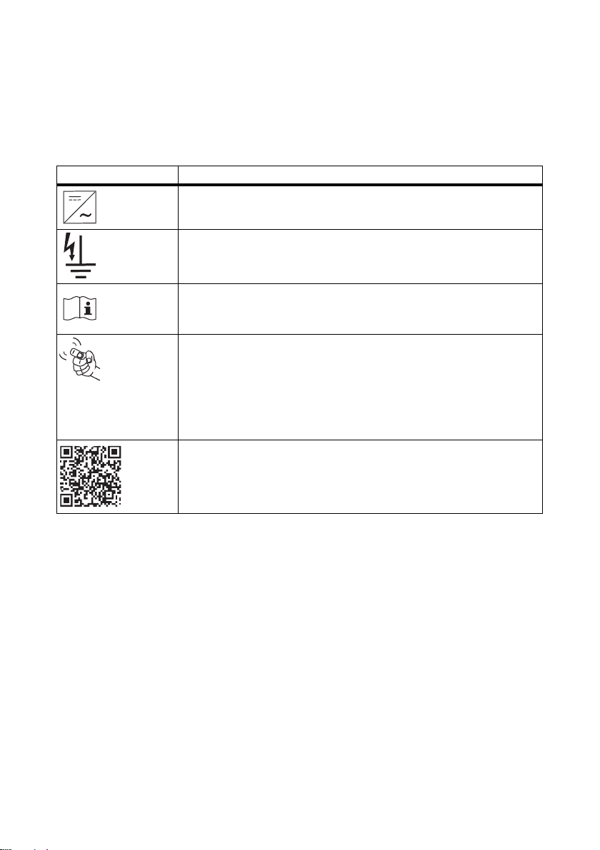
2.3.1 Symbols on the Inverter
Symbol Explanation
Operation display.
Indicates the operating state of the inverter.
Ground fault or varistor defective.
Read Section 9.3"Red LED Permanently On" (page71).
Error or disturbance
Read Section 9"Troubleshooting" (page65).
You can operate the display by tapping.
• Single tap: the backlight switches on or the display scrolls one
message further.
• 2 consecutive taps*: the inverter displays the startup phase message
once again (see Section 6.2"Display Messages in the Startup
Phase" (page49)).
QR-Code® ** for SMA bonus program
You will find information on the SMA bonus program at
www.SMA-Bonus.com.
* This function is valid from firmware version 2.18
** QR-Code is a registered wordmark of DENSO WAVE INCORPORATED.
Installation Manual WB5A_6A-IA-IEN114540 11
Page 12
Safety SMA Solar Technology AG
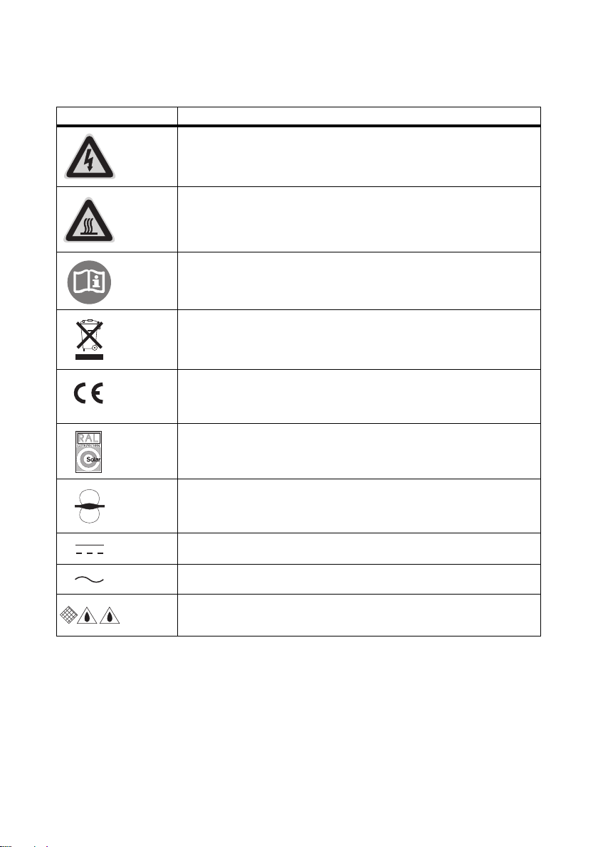
2.3.2 Symbols on the Type Label
Symbol Explanation
Beware of hazardous voltage.
The inverter operates at high voltages. All work on the inverter may be
carried out by electrically qualified persons only.
Beware of hot surface.
The inverter can become hot during operation. Avoid contact during
operation.
Observe all documentation that accompanies the inverter.
Th e in ver ter must not be d isp ose d of tog eth er w ith the hous eho ld waste. For
more information on disposal, see Section 10.4"Disposing of the Inverter"
(page75).
CE marking.
The inverter complies with the requirements of the applicable
EC guidelines.
RAL quality mark for solar products.
The inverter complies with the requirements of the German Institute for
Quality Assurance and Labeling.
The inverter has a transformer.
Direct current (DC)
Alternating current (AC)
The inverter is protected against dust intrusion and water jets from any
angle.
12 WB5A_6A-IA-IEN114540 Installation Manual
Page 13
SMA Solar Technology AG Unpacking
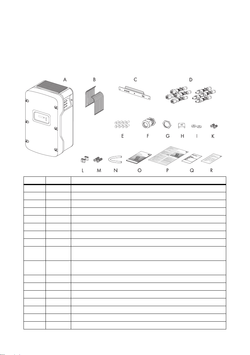
3 Unpacking
3.1 Scope of Delivery
Check the delivery for completeness and any visible external damage. Contact your specialty retailer
if anything is damaged or missing.
Object Quantity Description
A1 Inverter
B 2 Ventilation grid (1 x left, 1 x right)
C 1 Wall mounting bracket
D 8 DC connector (4 x positive, 4 x negative)
E 8 Sealing plug for DC connectors
F 1 Cable gland for AC connection
G 1 Counter nut for cable gland at AC connection
H 1 Clamping bracket for additional grounding
I 2 Conical spring washer
(1 x replacement for enclosure lid, 1 x for ground terminal)
K 2 M6x16 cheese-head screw
(1 x replacement for enclosure lid, 1 x for ground terminal)
L 2 Jumper (1 x for fan test, 1 x for the SMA Power Balancer wiring)
M2
N1 Silicone tube
O1 Installation manual
P1 User manual
Q 1 Document set with explanations and certificates
R 1 Supplementary sheet with inverter default settings
M6x8 cheese-head screw for securing the inverter in the wall mounting bracket
Installation Manual WB5A_6A-IA-IEN114540 13
Page 14

Unpacking SMA Solar Technology AG
3.2 Identifying the Inverter
You can identify the inverter using the type label. The type label is on the right-hand side of the
enclosure.
The serial number (Serial no.) and the type (Type / Model) of the product, as well as device-specific
characteristics are specified on the type label.
14 WB5A_6A-IA-IEN114540 Installation Manual
Page 15
SMA Solar Technology AG Mounting
4 Mounting
4.1 Safety
DANGER!
Danger to life due to fire or explosion
Despite careful construction, electrical devices can cause fires.
• Do not mount the inverter on flammable construction materials.
• Do not mount the inverter in areas where highly flammable materials are stored.
• Do not mount the inverter in a potentially explosive atmosphere.
CAUTION!
Risk of burns due to hot enclosure parts
• Mount the inverter in such a way that the enclosure cannot be touched inadvertently.
CAUTION!
Risk of injury due to the heavy weight of the inverter
• Note that the inverter weighs approx. 62 kg.
Installation Manual WB5A_6A-IA-IEN114540 15
Page 16
Mounting SMA Solar Technology AG
4.2 Selecting the Mounting Location
Consider the following requirements when selecting the mounting location:
• The mounting method and location must be suitable for the inverter's weight and dimensions
(see Section 11"Technical Data" (page76)).
• Mount on a solid surface.
• The mounting location must at all times be clear and safely accessible without the use of
additional aids such as scaffolding or lifting platforms. Non-fulfillment of these criteria may
restrict servicing.
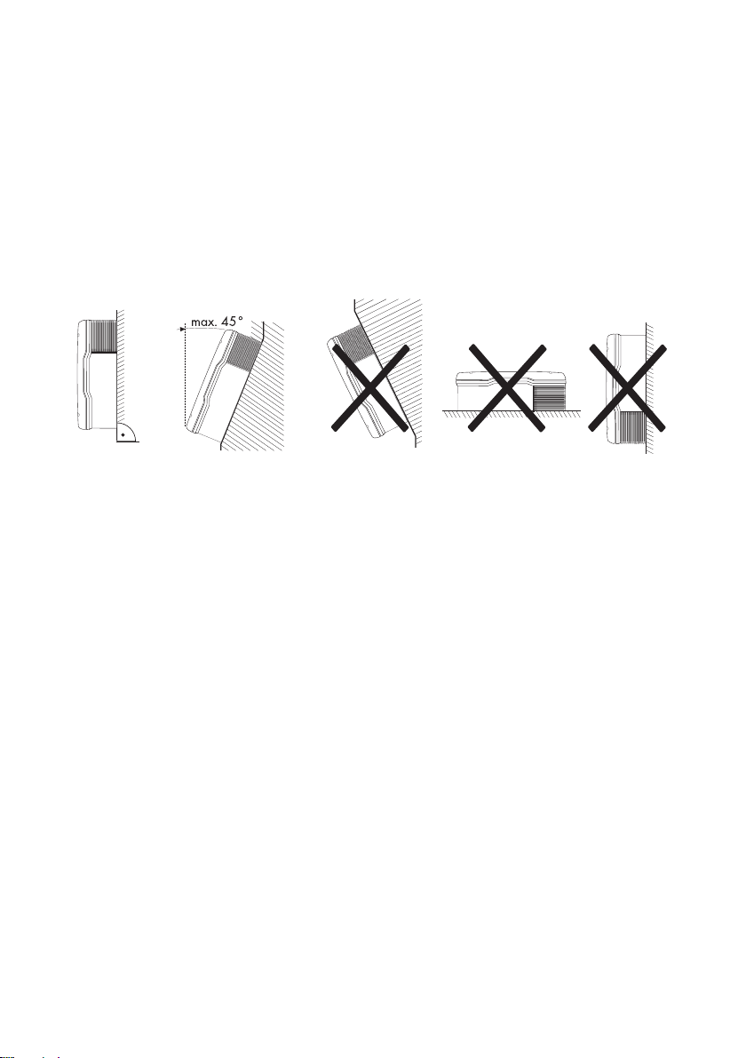
• Mount vertically or tilted backwards by max. 45 °.
• Never mount the device with a forward tilt.
• Never mount the device with a sideways tilt.
• Do not mount horizontally.
• The connection area must point downward.
• Install at eye level in order to allow operating states to be read at all times.
• To ensure optimal operation, the ambient temperature should be below 40°C.
• Do not expose the inverter to direct solar irradiation as this can cause excessive heating and
thus power reduction.
• In living areas, to avoid audible vibrations do not mount the device on plasterboard walls or
similar. When in operation, the inverter may emit noises which are perceived as annoying in
living areas.
16 WB5A_6A-IA-IEN114540 Installation Manual
Page 17
SMA Solar Technology AG Mounting
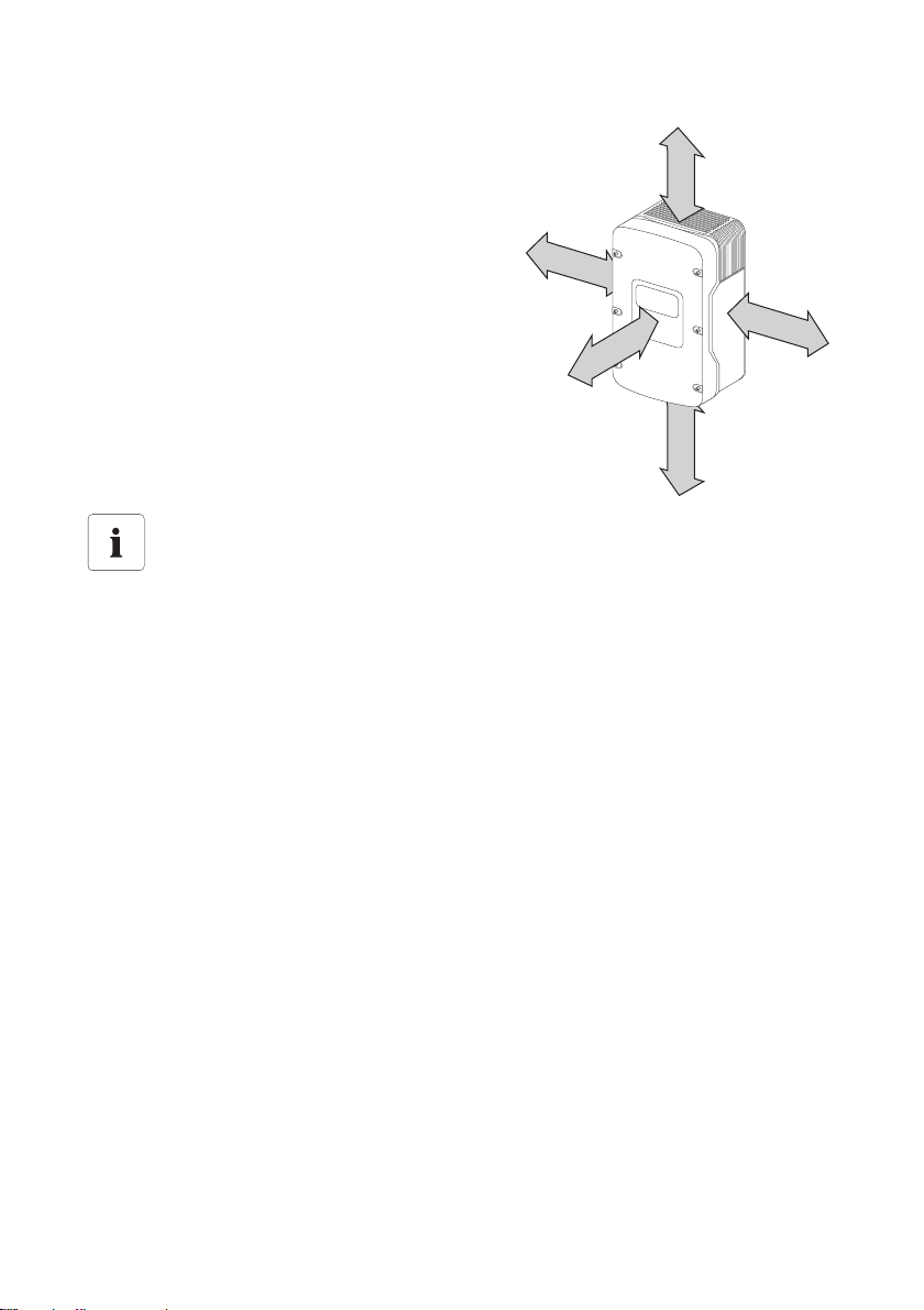
500 mm
300 mm
300 mm
50 mm
300 mm
• Observe minimum clearances as shown in the
diagram to walls, other inverters or objects, in order
to guarantee sufficient heat dissipation.
Multiple inverters installed in areas with high ambient temperatures
There must be sufficient clearance between the individual inverters to ensure that the
cooling air of the adjacent inverter is not drawn in.
If necessary, increase the spacing and make sure there is enough fresh-air supply to ensure
sufficient cooling of the inverters.
Installation Manual WB5A_6A-IA-IEN114540 17
Page 18
Mounting SMA Solar Technology AG
4.3 Mounting the Inverter with the Wall Mounting Bracket
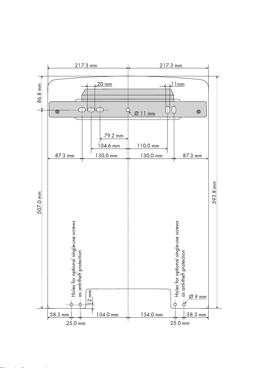
1. Mark the position of the drill holes using the wall mounting bracket and drill the holes.
Use at least 2 of the 6 holes, 1 hole each on the left- and right-hand sides respectively.
18 WB5A_6A-IA-IEN114540 Installation Manual
Page 19
SMA Solar Technology AG Mounting
CAUTION!
Risk of injury due to the heavy weight of the inverter
The inverter weighs approx. 62 kg.
• Mount the wall mounting bracket with the appropriate mounting material
(depending on the surface).
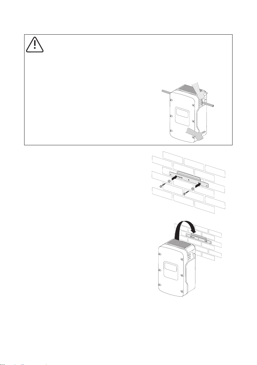
• U se the side h andle s (top and bo ttom ) or
a steel rod (maximum diameter 30 mm)
for transport and mounting. The rod must
be pushed through the enclosure
openings.
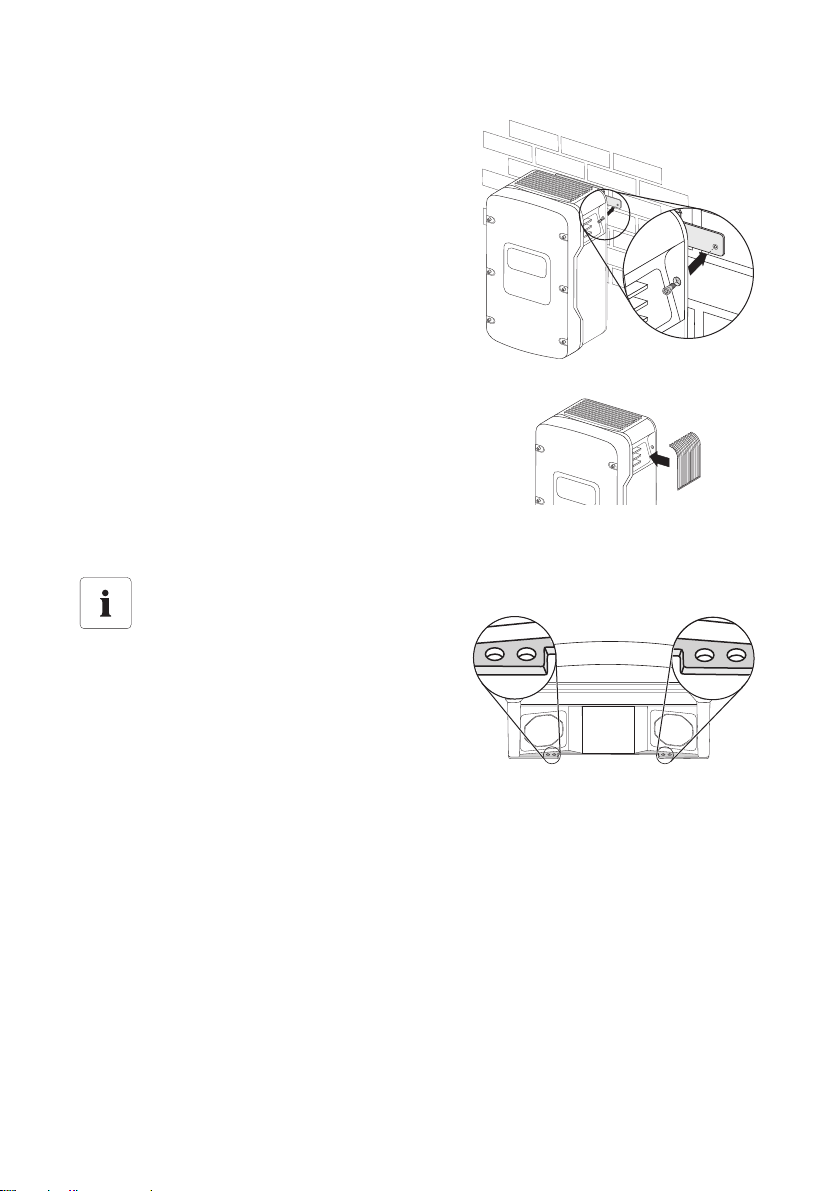
2. Secure the wall mounting bracket to the wall using
appropriate screws and washers.
3. Attach the inverter to the wall mounting bracket
using the special opening at the rear of the
enclosure.
Installation Manual WB5A_6A-IA-IEN114540 19
Page 20
Mounting SMA Solar Technology AG
4. Screw the inverter onto the wall mounting bracket
on both sides using the screws (M6x8) provided.
Only fasten the screws hand-tight.
5. Check to ensure that the inverter is securely in place.
6. Close the recessed grips with the ventilation grids
provided. To help you identify the sides, the
ventilation grids are marked on the inside with
"links/left" and "rechts/right".
The ventilation grids prevent intrusion of dust and
insects, and can be reordered from
SMA Solar Technology AG as required
(see Section 12"Accessories" (page83)).
Optional anti-theft protection
To protect the inverter against theft, the back
panel can be secured to the wall at the bottom
using 2 safety screws.
The other 2 holes are spares.
20 WB5A_6A-IA-IEN114540 Installation Manual
Page 21
SMA Solar Technology AG Electrical Connection
5 Electrical Connection
NOTICE!
Damage to the inverter due to electrostatic discharge
The internal components of the inverter can be irreparably damaged by electrostatic
discharge.
• Ground yourself before touching a component part.
5.1 Overview of the Connection Area
5.1.1 Exterior View
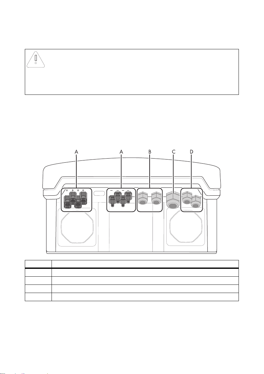
The following figure shows the assignment of the individual connection areas at the bottom of the
inverter.
Object Description
A DC connector for connecting the small wind turbine system
B Cable gland for optional communication via RS485 (PG16)
C Cable gland for grid connection (AC) (12 mm … 25 mm)
D Cable gland for SMA Power Balancer
Installation Manual WB5A_6A-IA-IEN114540 21
Page 22
Electrical Connection SMA Solar Technology AG
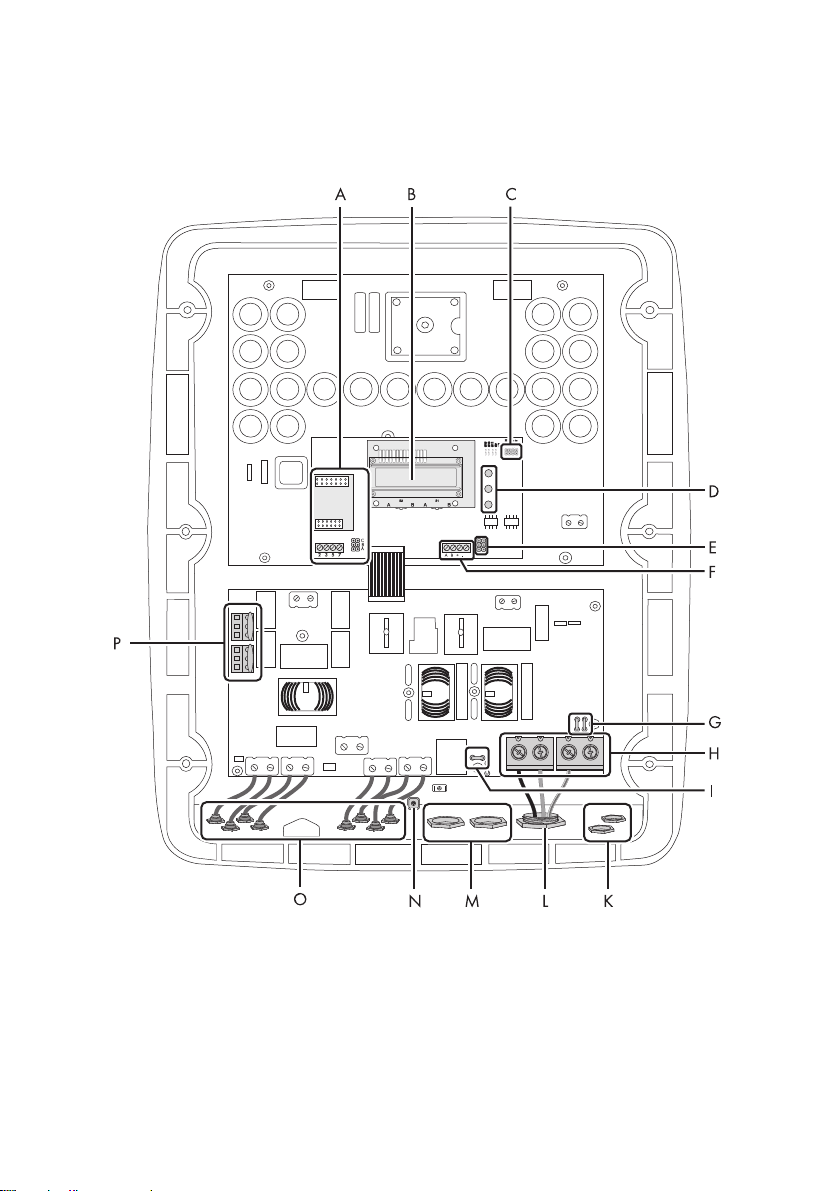
5.1.2 Interior View
The following figure shows the various components and connection areas of the open inverter.
22 WB5A_6A-IA-IEN114540 Installation Manual
Page 23
SMA Solar Technology AG Electrical Connection
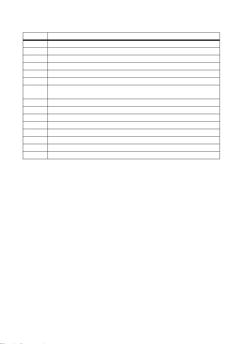
Object Description
A Connection area and slots for communication
BDisplay
C Jumper slot for the fan test
D LEDs for displaying the operating states
E Jumper slot for SMA Power Balancer
F Terminals for SMA Power Balancer
G Flat connector for grounding the cable shield when connecting the SMA Power
Balancer
H Terminals for grid cable (AC)
I Plug for grounding the cable shield for communication
K Cable gland for the SMA Power Balancer
L Cable gland for grid cable (AC)
M Cable gland for communication
N Screw fixture of shield clamp for data cable
ODC connector
PVaristors
Installation Manual WB5A_6A-IA-IEN114540 23
Page 24
Electrical Connection SMA Solar Technology AG
5.2 Connection to the Power Distribution Grid (AC)
5.2.1 Conditions for AC Connection
Connection requirements of the grid operator
Always observe the connection requirements of your grid operator.
Cable Design
The maximum cable lengths relative to the cable cross-section are shown in the following table.
Cable cross-section Maximum cable length
WB 5000A/WB 5000A-11 WB 6000A/WB 6000A-11
6 mm² 18 m 15 m
10 mm² 31 m 25 m
16 mm² 49 m 41 m
Reducing line losses by half
If three inverters with symmetrical feed-in are combined to form a three-phase system, the
neutral conductor is not subjected to any load, and the line losses are halved. This
reduction of line losses by 50% increases the maximum cable length by 100%.
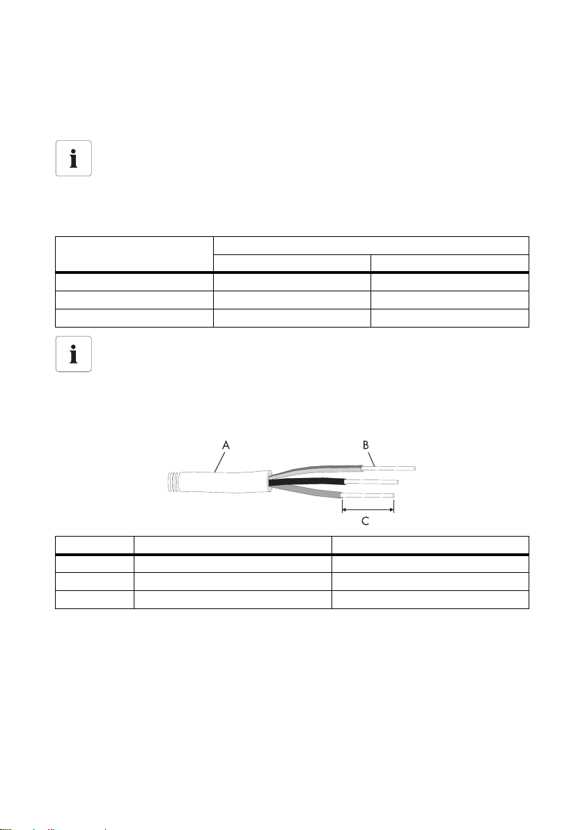
Cable Requirements
Object Description Value
A External diameter 12 mm ... 25 mm
B Cable cross-section 6 mm² ... 16 mm²
C Stripping length approx. 16 mm
24 WB5A_6A-IA-IEN114540 Installation Manual
Page 25
SMA Solar Technology AG Electrical Connection
Load Disconnection Unit
You must install a separate miniature circuit-breaker for each inverter in order to ensure that the
inverter can be securely disconnected under load. The maximum permissible fuse protection can be
found in Section 11"Technical Data" (page76).
Detailed information and examples on the design of miniature circuit-breakers are available in the
Technical Information "Miniature circuit-breaker" to be found in the download area of
SMA Solar Technology AG at www.SMA.de/en.
DANGER!
Danger to life due to fire
In the event of parallel connection of more than one inverter to the same miniature
circuit-breaker, the protective function of the miniature circuit-breaker is no longer
guaranteed. It can result in a cable fire or destruction of the inverter.
• Never connect several inverters to the same miniature circuit-breaker.
• Observe the maximum permissible fuse protection of the inverter when selecting the
miniature circuit-breaker.
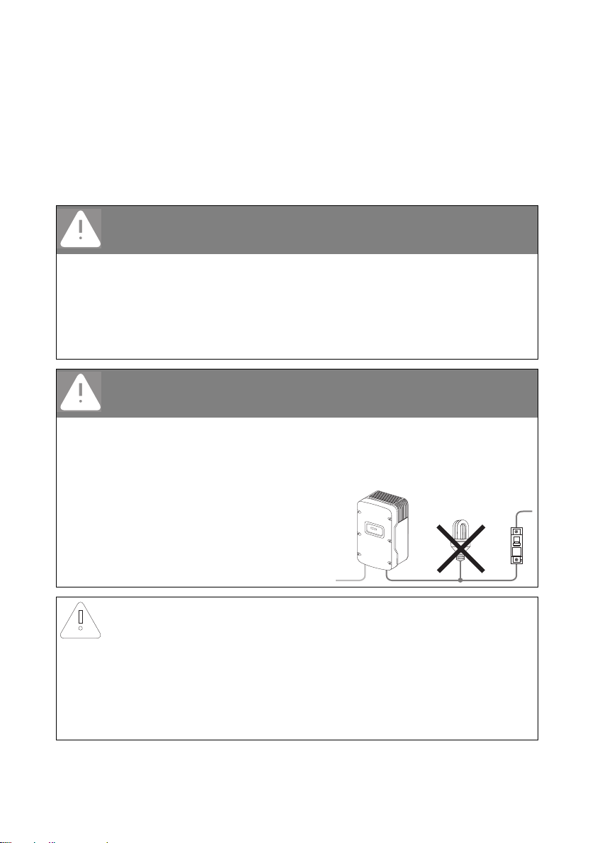
DANGER!
Danger to life through electric shock
When a generator (inverter) and a load are connected to the same miniature circuitbreaker, the protective function of the miniature circuit-breaker is no longer guaranteed.
The currents from the inverter and the grid can accumulate to form overcurrents that are not
detected by the miniature circuit-breaker.
• Never connect the load between the
inverter and the miniature circuit-breaker
without protection.
• Always protect the load separately.
NOTICE!
Damage to the inverter due to the use of screw-type fuses as load disconnection
units
A screw-type fuse, e.g., DIAZED fuse or NEOZED fuse, is not a switch-disconnector and
must never be used as such. A screw-type fuse only acts as cable protection.
Disconnection under load using a screw-type fuse can damage the inverter.
• Use o nly a switch-di sconnecto r or a mi niature circui t-breaker as a l oad dis conne ction
unit.
Installation Manual WB5A_6A-IA-IEN114540 25
Page 26
Electrical Connection SMA Solar Technology AG
5.2.2 Connecting the Inverter to the Power Distribution Grid (AC)
1. Check that the line voltage is within the permissible voltage range.
The exact operating range of the inverter is specified in the operating parameters. The relevant
document can be found in the download area at www.SMA.de/en,
in the "Technical Description" category of the respective inverter.
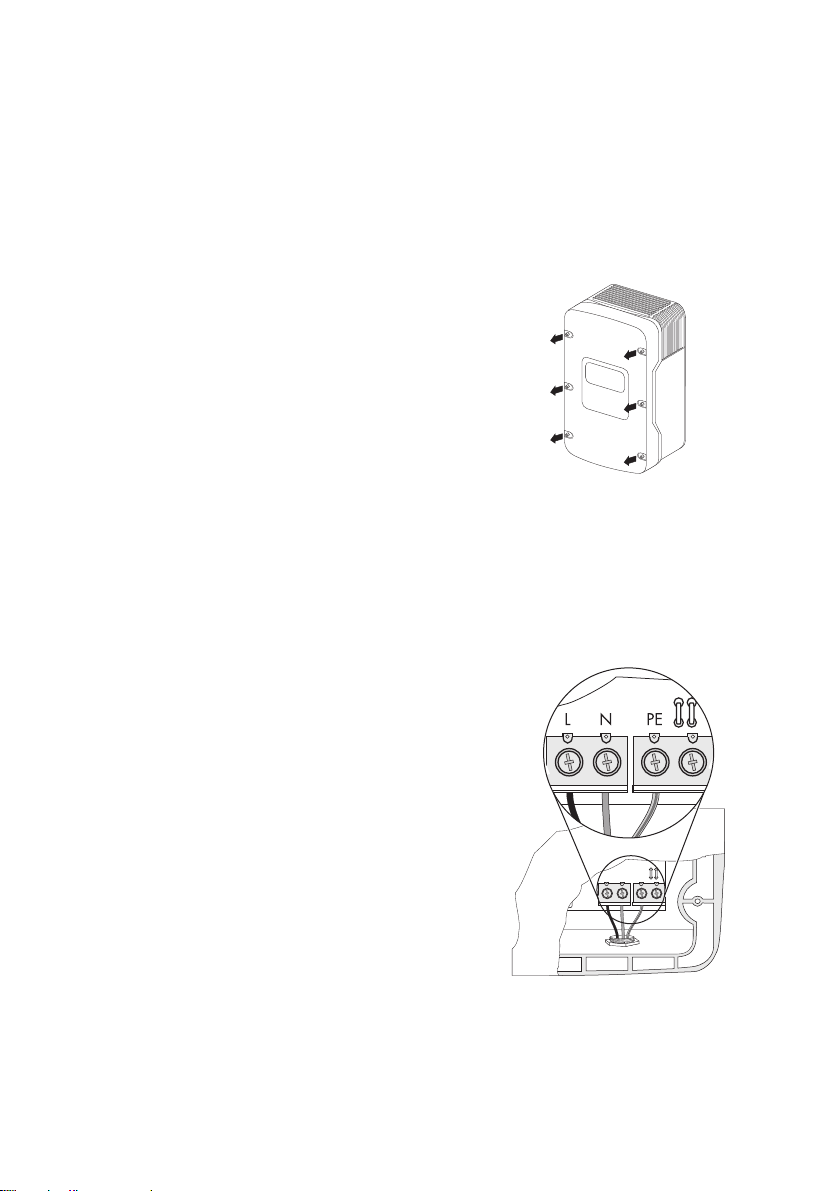
2. Disconnect the miniature circuit-breaker and secure against re-connection.
3. Loosen all screws of the enclosure lid and remove
the lid. To do this, use a hexagon socket wrench
(6 mm).
4. Remove the adhesive tape from the AC enclosure
opening.
5. Place the AC cable gland in position on the outside
of the enclosure opening and fasten with the
counter nut on the inside.
6. Pull the cable through.
7. Connect L, N and the protective conductor (PE) to
the terminal blocks using a screwdriver in
accordance with the labels.
The PE conductor must be 5 mm longer than the
L and N conductors.
L and N must not be swapped.
8. Fasten the cable gland tightly on the enclosure
opening.
26 WB5A_6A-IA-IEN114540 Installation Manual
Page 27
SMA Solar Technology AG Electrical Connection
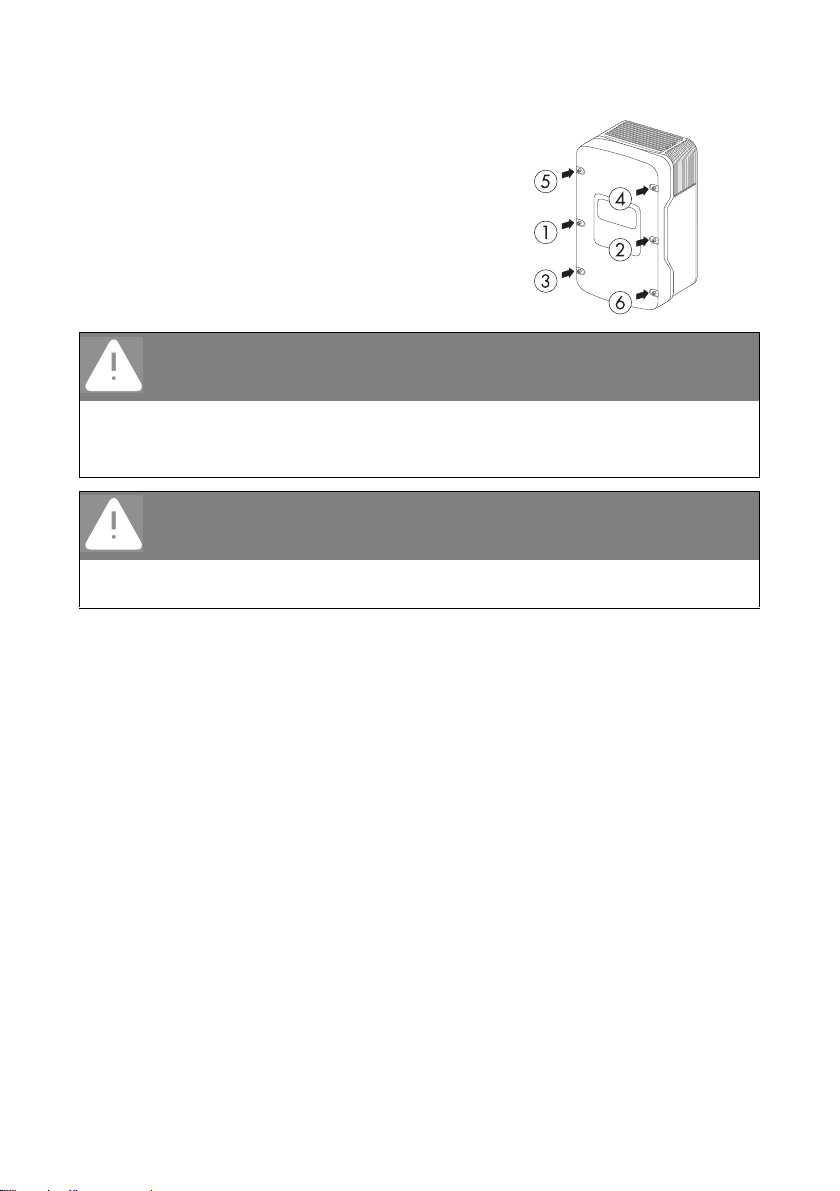
9. Secure the enclosure lid with all screws and the
corresponding conical spring washers. To do this,
use a hexagon socket wrench (6 mm).
Tighten the screws with 6 Nm torque in the order
shown in the figure on the right. The toothing of the
conical spring washers must point toward the
enclosure lid.
The scope of delivery of the inverter includes a
spare screw and a spare conical spring washer.
DANGER!
Danger to life due to live enclosure lid
The grounding of the enclosure lid is ensured by the conical spring washers.
• Atta ch the coni cal spring washers for all 6 screws wi th the toothing facing toward t he
enclosure lid.
DANGER!
Danger to life due to high voltages in the inverter
• Do not switch on the miniature circuit-breaker until the small wind turbine system has
been connected and the inverter is securely closed.
☑ The inverter is connected to the power distribution grid (AC).
Installation Manual WB5A_6A-IA-IEN114540 27
Page 28

Electrical Connection SMA Solar Technology AG
5.2.3 Additional Grounding of the Enclosure
If the installation so requires, you can use the ground terminal to connect a second protective
conductor or as equipotential bonding.
Procedure
1. Insert stripped grounding cable (D) underneath the
clamping bracket (C) (cross-section max. 16 mm²
or with bootlace ferrule max. 10 mm²).
2. Sec ure the clam pin g bracke t with th e screw ( A) and
washer (B).
The toothing of the washer must face toward the
clamping bracket.
☑ The inverter enclosure is additionally grounded.
You can ground multiple inverters as shown in the diagram below:
28 WB5A_6A-IA-IEN114540 Installation Manual
Page 29

SMA Solar Technology AG Electrical Connection
5.3 Setting the Display Language
You can set the display language using the switches underneath the display assembly inside the
inverter.
For inverters configured to the Italian country standard DK 5940, different switch positions apply.
You can find the standard to which the inverter was set upon delivery on the type label and the
enclosed supplement with the default settings. For more information, see the Technical Description
"Operating Parameters" at www.SMA.de/en.
Procedure
1. Open the inverter as described in Section 7.2"Opening the Inverter" (page57).
2. Set the switches to the required language as shown below.
For all country settings apart from DK 5940, the following switch positions apply:
Language Switch S2 Switch S1
German B B
English B A
French A B
Spanish A A
For inverters configured to the country standard
DK 5940, the following switch positions apply:
Language Switch S2 Switch S1
Italian B A
English A A
German B B
Spanish A B
3. Close the inverter as described in Section 7.3"Closing the Inverter" (page59).
☑ The display language is set.
Installation Manual WB5A_6A-IA-IEN114540 29
Page 30

Electrical Connection SMA Solar Technology AG
5.4 Connecting the Small Wind Turbine System (DC)
5.4.1 Conditions for the DC Connection
• The connection cables of the small wind turbine system must be fitted with connectors.
The DC connectors needed for DC connection are included in the delivery.
• The following limits at the DC input of the inverter must not be exceeded:
Maximum input voltage Maximum input current
600 V 26 A
DANGER!
Danger to life through electric shock or fire
The maximum possible input current is limited by the connectors used. If the connectors are
overloaded, an electric arc may occur and there is a risk of fire.
• Ensure that the input current does not exceed the maximum through-fault current of
the connectors used.
NOTICE!
Destruction of the inverter due to overvoltage
If the voltage of the small wind turbine system exceeds the maximum input voltage of the
inverter, the inverter can be destroyed by overvoltage. This will void all warranty claims.
• Install overvoltage protection, e.g. Windy Boy Protection Box, between the small
wind turbine system and the inverter.
30 WB5A_6A-IA-IEN114540 Installation Manual
Page 31

SMA Solar Technology AG Electrical Connection
5.4.2 Assembling the DC Connectors
For connection to the inverter, all connection cables of the small wind turbine system must be fitted
with the supplied DC connectors.
To assemble the DC connectors, proceed as follows. Ensure the connectors have the correct polarity.
The DC connectors are marked with the symbols "+" and " − ".
Cable requirements:
• Use a PV1-F cable.
Procedure
1. Lead the stripped cable all the way into the plug.
2. Press the clamping bracket down until it audibly
snaps into place.
3. Ensure that the cable is correctly inserted:
Result Measure
☑ If the stranded wires are visible in the
chamber of the clamping bracket, the cable
is correctly inserted.
Installation Manual WB5A_6A-IA-IEN114540 31
• Proceed to step 4.
Page 32

Electrical Connection SMA Solar Technology AG
+
Result Measure
☑ If the stranded wires are not visible, the
cable is not correctly inserted.
• Loosen the clamping bracket. To do so,
insert a screwdriver into the clamping
bracket to lever it open
(blade width: 3.5 mm).
• Remove the cable and go back to step 1.
4. Slide the screw joint up to the thread and fasten with a torque of 2 Nm.
☑ The DC connectors are assembled and can now be connected to the inverter as described in
Section 5.4.4"Connecting the Small Wind Turbine System (DC)" (page34).
32 WB5A_6A-IA-IEN114540 Installation Manual
Page 33

SMA Solar Technology AG Electrical Connection
5.4.3 Opening the DC Connector
1. Unscrew the screw connection.
2. Release the DC connector. To do so, insert a
screwdriver into the lateral shaft latching and lever
it open (blade width: 3.5 mm).
3. Carefully pull the DC connector apart.
4. Loosen the clamping bracket. To do so, insert a
screwdriver into the clamping bracket to lever it
open (blade width: 3.5 mm).
5. Remove the cable.
☑ The cable is now detached from the DC connector.
Installation Manual WB5A_6A-IA-IEN114540 33
Page 34

Electrical Connection SMA Solar Technology AG
5.4.4 Connecting the Small Wind Turbine System (DC)
DANGER!
Danger to life due to high voltages in the inverter
• Before connecting the small wind turbine system, ensure that it is not running.
NOTICE!
Destruction of the inverter due to overvoltage
• If the output voltage of the small wind turbine system exceeds the maximum input
voltage of the inverter, do not connect any DC cables to the inverter and check the
design of the plant.
1. Connect the assembled DC connectors to the inverter.
☑ The DC connectors click audibly into position.
To release the DC connectors, see Section 7.2"Opening the Inverter" (page57).
34 WB5A_6A-IA-IEN114540 Installation Manual
Page 35

SMA Solar Technology AG Electrical Connection
+
1
2
+
+
2. To seal the inverter, any unused DC inputs must be closed with DC connectors and sealing
plugs.
Sealing plugs
•Do NOT insert the sealing plugs DIRECTLY into the DC inputs on the inverter.
– For unused DC connectors, push down the
clamping bracket and slide the screw joint up to
the thread.
– Insert sealing plug into the DC connector.
– Fasten the DC connector (torque: 2 Nm).
– Insert the DC connectors with sealing plugs into
the corresponding DC inputs on the inverter.
☑ The DC connectors click audibly into position.
3. Ensure that all DC connectors are securely in place.
☑ The small wind turbine system is connected.
You can now commission the inverter as described
in Section 6"Commissioning" (page48).
The following connections are optional.
Installation Manual WB5A_6A-IA-IEN114540 35
Page 36

Electrical Connection SMA Solar Technology AG
5.5 Connection of the SMA Power Balancer
The inverter is standardly equipped with the SMA Power Balancer. This enables a circuitry of
3 inverters to a three-phase feed-in system.
Each of the three inverters in a group must be connected to a different line conductor of the
low-voltage grid (L1, L2, L3)!
If this electronic circuit is activated, you can specify how the other two inverters should react if there
is a device fault in the third inverter or a line voltage fault occurs in its phase.
The connections for the SMA Power Balancer are galvanically isolated from the rest of the inverter
electronic circuit.
5.5.1 Configuration
With configured country standard VDE-AR-N4105-MP or VDE-AR-N4105-HP, in the WB 5000A-11
and WB 6000A-11, the default setting of the SMA Power Balancer is activated and set to the
operation mode "PowerGuard". With all other country standards, the default setting of the
SMA Power Balancer in WB 5000A-11 und WB 6000A-11 is deactivated.
In WB 5000A/WB 5000A-IT/WB 6000A/WB 6000A-IT, the default setting of the
SMA Power Balancer is always deactivated, regardless of the configured country standard.
The SMA Power Balancer can be activated and configured via a communication product. To change
the "PowerBalancer" parameter, you need a personal access code, the so-called SMA Grid Guard
code. The application form for the personal access code is available in the download area at
www.SMA.de/en, in the "Certificate" category of the respective inverter.
The configuration options are described below.
36 WB5A_6A-IA-IEN114540 Installation Manual
Page 37

SMA Solar Technology AG Electrical Connection
Configuration Options
There are 4 different configuration options for the "PowerBalancer" parameter.
Local connection requirements
Select the respective setting and always observe the local connection requirements and
provisions of your grid operator.
•FaultGuard
– If one of the 3 inverters indicates a line voltage fault and stops feeding in, the other two
inverters also disconnect from the power distribution grid immediately.
– If one of the 3 inverters indicates a device fault and stops feeding in, the other two inverters
also disconnect from the power distribution grid 5 minutes later.
Installation Manual WB5A_6A-IA-IEN114540 37
Page 38

Electrical Connection SMA Solar Technology AG
•PhaseGuard
This operating mode enables the implementation of three-phase line voltage monitoring.
– If one of the 3 inverters indicates a line voltage fault and stops feeding in, the other two
inverters also disconnect from the power distribution grid automatically.
– If one of the three inverters indicates a device fault and stops feeding in, the other two
inverters are not affected and continue to feed in at full power.
38 WB5A_6A-IA-IEN114540 Installation Manual
Page 39

SMA Solar Technology AG Electrical Connection
•Off
The SMA Power Balancer is deactivated.
– If one of the inverters displays a device fault or a line voltage fault , only the affected
inverter disconnects from the power distribution grid and the other two inverters continue to
feed in at full power.
Installation Manual WB5A_6A-IA-IEN114540 39
Page 40

Electrical Connection SMA Solar Technology AG
•PowerGuard
This setting can be carried out if the entire small wind turbine system consists of 3 inverters only
and the asymmetric load is to be limited to 4.6 kVA in case of failure.
Differing asymmetric load limit for Italy
In inverters configured to country standard DK 5940, the asymmetric load is limited to
6kVA.
– If one of the 3 inverters indicates a line voltage fault or a device fault and stops feeding
in, the other two inverters automatically limit their power to 4.6 kVA.
5.5.2 Cabling
Cable Requirements
To connect the SMA Power Balancer, use a "LiYCY" cable with the following structure:
• Indoors: LiYCY 2 x 2 x 0.25
• Outdoors: Li-2YCYv 2 x 2 x 0.25
Object Description
A Flexible insulation
BShielding
2
C Twisted pair 2 (2 x 0.25 mm
D Twisted pair 1 (2 x 0.25 mm²)
40 WB5A_6A-IA-IEN114540 Installation Manual
)
Page 41

SMA Solar Technology AG Electrical Connection
Overview of the Connection Area
Position Description
A Screw terminals for the wire bridge
B Screw terminals for connecting the cables
CJumper slot
D Flat connector for grounding the cable shield
E Silicone tube / cable route
F Cable gland
Installation Manual WB5A_6A-IA-IEN114540 41
Page 42

Electrical Connection SMA Solar Technology AG
Procedure
1. Open the inverter as described in Section 7.2"Opening the Inverter" (page57).
2. Insert the cable into each inverter.
Use one of the two enclosure openings (F) on the bottom right hand side.
DANGER!
Danger to life due to high voltages on the SMA Power Balancer cable when
faults occur
• Sheath the positive and negative cable conductors in each inverter using the silicone
tube provided.
• Cut the silicone tube to the required length.
• The silicone tube must completely protect the cable inside the inverter.
3. Lead the cable along the cable route (E) as far as the terminal block (B).
4. Ground the cable shield in each inverter at the PE terminal (D).
5. Sheath the positive and negative cable conductors in each inverter with end sleeves.
6. Connect the positive and negative pole to the
corresponding screw terminals.
7. To connect the 3 inverters, connect the positive and negative cables from the 2 other inverters
to the terminal block of the middle inverter.
The length of the cables between 2 inverters must not exceed 300 m.
42 WB5A_6A-IA-IEN114540 Installation Manual
Page 43

SMA Solar Technology AG Electrical Connection
8. Only in the middle inverter
(the one with 2 insulated conductors per terminal),
insert one of the jumpers provided into the lowest of
the three slots as depicted on the right.
Do not plug the jumpers into the bottom slot of the
two other inverters.
or
Bridge the "A" and "B" screw terminals on the
middle inverter with a wire bridge.
Do not bridge the "A" and "B" screw terminals in
the two other inverters!
9. Measure the resistance between the positive and
negative poles of the terminal block in the middle
inverter.
☑ If the resistance is approximately 27.8 k Ω
(±370 Ω ), the SMA Power Balancer has been
connected correctly. Otherwise, check the
cabling.
10. Close all inverters as described in Section
7.3"Closing the Inverter" (page59).
Installation Manual WB5A_6A-IA-IEN114540 43
Page 44

Electrical Connection SMA Solar Technology AG
E-today 0Wh
Mode MPP
Disturbance
PowerBalance
Disturbance
Vac-Bfr
Disturbance
PowerBalance
5.5.3 Function Test
To test whether the SMA Power Balancer is operating correctly, proceed as follows:
1. Select the "PhaseGuard" setting of the "PowerBalancer" parameter for all three inverters.
2. Check whether all inverters in the group are feeding into the power distribution grid normally.
☑ Green LED glows continuously, or you see the
display message on the right: Proceed to step 3.
or
☑ If all the inverters in this group are displaying the
message on the right: check installation of the
SMA Power Balancer and contact the
SMA Service Line if necessary.
3. Switch off the miniature circuit-breaker in 1 of the
3 inverters.
• The inverter with the deactivated miniature circuitbreaker will then indicate a line voltage fault by the
display message pictured on the right
("Bfr" and "Srr" are irrelevant).
• The other 2 inverters will then also disconnect from
the power distribution grid, showing the display
message pictured on the right.
• Both inverters subsequently switch to "Balanced"
mode.
☑ If the inverters react as described above, the
function test has been completed successfully.
Otherwise, check the configuration.
4. If applicable, reset the "PowerBalancer" parameter
to the desired setting in all inverters.
5. Switch on the miniature circuit-breaker again.
☑ The function test is complete.
44 WB5A_6A-IA-IEN114540 Installation Manual
Page 45

SMA Solar Technology AG Electrical Connection
5.6 Communication
The inverter is equipped with a slot for communication interfaces which enable it to communicate with
data loggers (e.g., Sunny WebBox) or a PC with appropriate software (e.g., Sunny Explorer).
Refer to the communication interface manual for a detailed wiring diagram and installation
instructions.
The Power Reducer Box by SMA Solar Technology AG enables the active power of the inverter to be
limited or the displacement power factor to be set via external specification.
For detailed information on the Power Reducer Box, see the relevant technical description at
www.SMA.de/en.
5.7 Setting the Grid and Country Parameters
Changing grid-relevant and country parameters
To change grid-relevant parameters, you need a personal access code – the so-called
SMA Grid Guard code. The application form for the personal access code is available in
the download area at www.SMA.de/en, in the "Certificate" category of the respective
inverter.
Confirm the changes to these parameters with your grid operator.
A detailed description of the operating parameters for the inverter is available in the download area
at www.SMA.de/en in the category "Technical Description" of the respective inverter.
5.7.1 Setting the Country of Installation
Using the "Default" parameter, you can set the country of installation and/or the grid connection
standard valid for that country via a communication product (e.g., Sunny WebBox) or a PC with
corresponding software (e.g., Sunny Data Control or Sunny Explorer). However, this is only required
if the inverter was originally ordered for another country. You can find the standard to which the
inverter was set upon delivery on the type label and the enclosed supplement with the default settings.
Installation Manual WB5A_6A-IA-IEN114540 45
Page 46

Electrical Connection SMA Solar Technology AG
5.7.2 Setting Off-Grid Operation
To operate the inverter in an off-grid system with Sunny Island, you must set the inverter via the
"Default" parameter to off-grid operation ("OFF-Grid") operation.
You have several possibilities to set the inverter to off-grid operation:
• Setting via Sunny WebBox
or
• Setting via Sunny Data Control or Sunny Explorer
DANGER!
Danger to life due to high voltages in the event of outage of the power
distribution grid
If you set the inverter to off-grid operation, it does not fulfill any country-specific standards
or guidelines. If there is a power distribution grid outage, there will consequently be a
danger of back-feed.
• Never op era te t he i nve rte r di rec tly on t he p owe r di str ibu tio n gr id w hen set to off-grid
operation.
46 WB5A_6A-IA-IEN114540 Installation Manual
Page 47

SMA Solar Technology AG Electrical Connection
5.8 Polynomial Curve
The polynomial curve is a programmable power curve depending on the DC input voltage.
By adapting the default polynomial curve to the small wind turbine system being used, you can
optimize the energy output of the small wind turbine system.
To adapt the polynomial curve of the inverter to the small wind turbine system being used, you should
change the following parameters on the PC with the "Windy Boy Setup Tool" (www.SMA.de/en):
•Vpv-Start
• UdcWindStart
• Wind_a0 ... Wind_a3
•Pmax
•P-Wind-Ramp
•KP-Wind-Reg
•KI-Wind-Reg
•T-Stop
A description of the operating parameters is available in the download area at www.SMA.de/en in
the category "Technical Description" of the respective inverter.
The inverter regulates its output power according to the generator voltage. The following diagram
shows the function of a typical polynomial curve in a WB 5000A/WB 5000A-11/WB 6000A/
WB 6000A-11. Here, the AC power fed in is depicted as a function of the DC input voltage of the
inverter.
Installation Manual WB5A_6A-IA-IEN114540 47
Page 48

Commissioning SMA Solar Technology AG
6 Commissioning
6.1 Commissioning the Inverter
1. Check the following requirements before commissioning:
– The inverter is correctly mounted and connected.
– The miniature circuit-breaker is correctly dimensioned.
– The small wind turbine system is correctly grounded in accordance with the instructions of
the manufacturer.
– The rectifier and overvoltage protection (e.g. Windy Boy Protection Box) are installed
between the small wind turbine system and the inverter
– Unused DC inputs are closed using the corresponding DC connectors and sealing plugs.
2. Switch on the miniature circuit-breaker.
3. Commission the small wind turbine system in accordance with the instructions of the
manufacturer.
☑ All 3 LEDs lit or flashing: the startup phase commences.
☑ Green LED lit: commissioning was successful.
or
☑ Green LED flashing: grid connection conditions have not yet been reached.
or
☑ Red LED lit or flashing: a disturbance has occurred. Proceed to step 4.
Object Description
A Green LED: operation
B Red LED: ground fault or varistor
defective
C Yellow LED: disturbance
Self-test in accordance with DK 5940, Ed. 2.2 for initial commissioning
(applies to Italy only)
The Italian standard DK 5940 requires that an inverter may only b e op era ted on the po wer
distribution grid if the disconnection times for overvoltage, undervoltage, minimum
frequency and maximum frequency have been tested.
Start the self-test as described in Section 6.3"Self-test in Accordance with DK 5940, Ed.
2.2 (Applies to Italy Only)" (page50). The test takes approx. 8 minutes.
4. Read Section 9"Troubleshooting" (page65) and if necessary, eliminate the error or fault.
48 WB5A_6A-IA-IEN114540 Installation Manual
Page 49

SMA Solar Technology AG Commissioning
PowerBalancer
PowerGuard
6.2 Display Messages in the Startup Phase
• After commissioning, the inverter displays the
device type in the startup phase.
• A fte r 5 seco nds or a fu rth er tap o n th e enclos ure lid,
the inverter displays the firmware version of the
internal processors.
• A fte r anoth er 5 second s or a fu rther t ap, the inv ert er
displays the configured country standard
(example: "VDE-AR-N4105-MP").
• A fte r anoth er 5 second s or a fu rther t ap, the inv ert er
displays the configured operating mode of the
SMA Power Balancer (example: "PowerGuard").
Show display messages again (applicable from firmware version 2.18)
To have the startup phase messages displayed again during operation, tap on the
enclosure twice in rapid succession.
Installation Manual WB5A_6A-IA-IEN114540 49
Page 50

Commissioning SMA Solar Technology AG
6.3 Self-test in Accordance with DK 5940, Ed. 2.2 (Applies to Italy Only)
6.3.1 Starting the Self-Test by Tapping
You can start the test of the disconnection times by tapping on the enclosure lid. The requirement for
this is that the country configuration of the inverter has been set to Italy ("IT/DK5940 ") or "trimmed".
Proceed as follows for checking the disconnection times:
1. Connect the small wind turbine system to the inverter. The inverter can only initialize once the
small wind turbine system is producing enough power. It is therefore not possible to test the
disconnection time if there is no wind.
2. Connect the inverter on the AC side. To do this, you must execute the AC connection
(AC plug or direct connection) and/or switch on the miniature circuit-breaker on the grid supply
line (fuse and circuit-breaker).
3. The inverter is now in the startup phase, i.e. all 3 LEDs are simultaneously lit.
Start the self-test immediately after all 3 LEDS have gone out by tapping on the display of the
inverter.
4. The display will ask whether you would like to start
the test sequence. Confirm by tapping on the
display again within 30 seconds.
Once you have started the test sequence, the inverter will consecutively check the disconnection times
for overvoltage, undervoltage, maximum frequency and minimum frequency. During the test, the
inverter will display the values described in Section 6.3.2"Completion of the Self-test" (page51).
50 WB5A_6A-IA-IEN114540 Installation Manual
Page 51

SMA Solar Technology AG Commissioning
6.3.2 Completion of the Self-test
Note the values which are displayed during the self-test. These values must be entered in a test report.
The results of each test test are displayed 3 times, one after the other. The respective message is
displayed for 10 seconds.
In the self-test, the upper and lower disconnection thresholds for each protective function are adjusted
on a linear basis with a variation of 0.05 Hz/s and 0.05 Vn/s for frequency and voltage monitoring.
As soon as the actual measured value goes outside the permitted range
(adjusted disconnection threshold), the inverter disconnects from the power distribution grid.
Thus, the inverter determines the reaction time and performs the self-test.
Overvoltage Test
The inverter begins with the overvoltage test. During the
test sequence, the voltage limit applied is shown in the
display of the inverter.
The voltage is reduced step by step until the
disconnection threshold is reached and the inverter
disconnects from the power distribution grid.
Once the inverter has disconnected from the power distribution grid, the display successively shows
the following values:
•Disconnection value,
•Calibration value,
•Reaction time,
• Current line voltage.
Installation Manual WB5A_6A-IA-IEN114540 51
Page 52

Commissioning SMA Solar Technology AG
Undervoltage Test
After the overvoltage test, the inverter proceeds to carry
out the undervoltage test. During the test sequence, the
current calibration value of the voltage limit applied is
shown in the display of the inverter.
The voltage is increased step by step until the
disconnection threshold is reached and the inverter
disconnects from the power distribution grid.
Once the inverter has disconnected from the power distribution grid, the display successively shows
the following values:
•Disconnection value,
•Calibration value,
•Reaction time,
• Current line voltage.
52 WB5A_6A-IA-IEN114540 Installation Manual
Page 53

SMA Solar Technology AG Commissioning
Maximum Frequency
In a third step, the inverter tests the maximum frequency.
During the test sequence, the frequency limit applied is
shown in the display of the inverter.
The frequency is reduced step by step until the
disconnection threshold is reached and the inverter
disconnects from the power distribution grid.
Once the inverter has disconnected from the power distribution grid, the display successively shows
the following values:
•Disconnection value,
•Calibration value,
•Reaction time,
• Current power frequency
Installation Manual WB5A_6A-IA-IEN114540 53
Page 54

Commissioning SMA Solar Technology AG
Minimum Frequency
In the last step, the inverter tests the minimum frequency.
During the test sequence, the frequency limit applied is
shown in the display of the inverter.
The frequency is increased step by step until the
disconnection threshold is reached and the inverter
disconnects from the power distribution grid.
Once the inverter has disconnected from the power
distribution grid, the display successively shows the following values:
•Disconnection value,
•Calibration value,
•Reaction time,
• Current power frequency
When the inverter has carried out all four tests, it switches to the "Turbine" operating mode. The
original calibration values are then reset and the inverter automatically connects to the power
distribution grid. If you wish to repeat the test, you must switch off the inverter, i.e. disconnect it on the
AC and DC sides, and then recommission. You can then restart the self-test as described in Section
6.3.1"Starting the Self-Test by Tapping" (page50). The inverter recommences the test sequence as
described in Section 6.3.2"Completion of the Self-test" (page51).
54 WB5A_6A-IA-IEN114540 Installation Manual
Page 55

SMA Solar Technology AG Commissioning
6.4 Operating States of the Inverter
Startup Procedure
If the inverter has enough voltage and power, the three LEDs on the inverter light up simultaneously,
indicating that the startup process is ongoing.
As soon as the DC input voltage reaches the value configured for the parameter "Vpv-Start", the
inverter trips several self-tests, measuring procedures and synchronization with the power distribution
grid. This operating state is indicated on the inverter by the flashing green LED.
Once the DC input voltage has reached the "Vpv-Start" value for the time configured in "T-Start" and
all the tests have been completed successfully, the inverter connects to the power distribution grid and
the green LED comes on permanently. T he i nve rte r th en s wit ches to characteristic curve operation, and
regulates the input current according to the generator voltage.
Characteristic Curve Operation
After the startup procedure, the inverter switches to characteristic curve operation and regulates the
input current according to the generator voltage.
The inverter then begins to exert a load on the small wind turbine system, draws power from the small
wind turbine system according to the input voltage present, and then feeds it into the power
distribution grid. The maximum power output corresponds to the maximum AC power of the inverter.
However, it can be reduced using the "Pmax" parameter.
Shutdown Procedure
If wind strength is so low that the DC input voltage falls below an internally calculated value, the
inverter stops feeding power to the power distribution grid for the period defined in "T-Stop". As soon
as DC input voltage increases again, the inverter switches back to characteristic curve operation.
If the DC input voltage remains below an internally calculated value for the time set in "T-Stop", the
inverter will switch off.
If the DC input voltage is no longer sufficient to supply the on-board electronics with power, the
inverter switches off immediately.
Installation Manual WB5A_6A-IA-IEN114540 55
Page 56

Opening and Closing SMA Solar Technology AG
7 Opening and Closing
7.1 Safety
DANGER!
Electric shock due to high voltages in the inverter
Before opening the inverter, observe the following:
• Ensure that no voltage is present on the AC side.
•Ensure that no voltage or current is present on the DC side.
NOTICE!
Damage to the inverter due to electrostatic discharge
The internal component parts of the inverter can be irreparably damaged by electrostatic
discharge.
• Ground yourself before touching a component part.
56 WB5A_6A-IA-IEN114540 Installation Manual
Page 57

SMA Solar Technology AG Opening and Closing
7.2 Opening the Inverter
1. Stop the small wind turbine system and make sure that it cannot restart.
2. Disconnect the miniature circuit-breaker and secure against re-connection.
3. Use a current probe to make sure all DC cables are
current free.
☑ If current is present, check the installation.
4. Release and pull off all DC connectors with a
screwdriver (blade width: 3.5 mm):
– Insert a screwdriver into one of the side slots (1).
– Remove the DC connector by pulling straight
down (2). Do not pull the cable.
DANGER!
Danger to life due to high voltages in the inverter
The capacitors in the inverter take 5 minutes to discharge.
• Wait 5 minutes before opening the inverter.
Installation Manual WB5A_6A-IA-IEN114540 57
Page 58

Opening and Closing SMA Solar Technology AG
5. Loosen all screws of the enclosure lid. To do this,
use a hexagon socket wrench (6 mm).
6. Remove enclosure lid by pulling towards you.
7. Verify the absence of voltage L to N at the AC
terminal with a suitable instrument.
☑If voltage is present, check the installation.
8. Verify the absence of voltage L to PE at the
AC terminal with a suitable instrument.
☑If voltage is present, check the installation.
☑ The inverter is open and no voltage is present.
58 WB5A_6A-IA-IEN114540 Installation Manual
Page 59

SMA Solar Technology AG Opening and Closing
7.3 Closing the Inverter
1. Secure the enclosure lid with the 6 screws and the
corresponding conical spring washers. To do this,
use a hexagon socket wrench (6 mm).
Tighten the screws with 6 Nm torque in the order
shown in the figure on the right. The toothing of the
conical spring washers must point toward the
enclosure lid.
The scope of delivery of the inverter includes a
spare screw and a spare conical spring washer.
DANGER!
Danger to life due to live enclosure lid
The grounding of the enclosure lid is ensured by the conical spring washers.
• Atta ch the coni cal spring washers for all 6 screws wi th the toothing facing toward t he
enclosure lid.
2. Check the DC connectors for correct polarity and connect them to the inverter. To release the
DC connectors, see Section 7.2"Opening the Inverter" (page57).
☑ The DC connectors click audibly into position.
To release the DC connectors, see Section 7.2"Opening the Inverter" (page57).
3. Close all unused DC inputs as described in Section 5.4.4"Connecting the Small Wind Turbine
System (DC)" (page34) to seal the inverter.
4. Ensure that all DC connectors are securely in place.
5. Switch on the miniature circuit-breaker.
6. Commission the small wind turbine system in accordance with the instructions of the
manufacturer.
Installation Manual WB5A_6A-IA-IEN114540 59
Page 60

Opening and Closing SMA Solar Technology AG
7. Check whether the display and the LEDs indicate a
normal operating state
(see Section 6"Commissioning" (page48)).
☑ The inverter is closed and in operation.
60 WB5A_6A-IA-IEN114540 Installation Manual
Page 61

SMA Solar Technology AG Maintenance and Cleaning
8 Maintenance and Cleaning
8.1 Cleaning the Inverter
If the inverter is soiled and visibility of inverter operating data and operating modes is restricted, wipe
the enclosure lid, display and LEDs clean with a damp cloth. Do not use any caustic substances
(e.g., solvents, abrasives) for cleaning.
8.2 Checking the Heat Dissipation
8.2.1 Cleaning the Fans
If the fan guards are just clogged with loose dust, clean them with a vacuum cleaner. If you do not
achieve satisfactory results with a vacuum cleaner, dismantle the fans for cleaning.
Procedure
DANGER!
Danger to life due to high voltages in the inverter
• Stop the small wind turbine system and make sure that it cannot restart.
• Disconnect the inverter on the AC and DC sides.
1. Disconnect the inverter from both the DC and AC sides as described in Section 7.2"Opening
the Inverter" (page57).
2. Wait for the fans to stop rotating.
Cleaning the Fan Guards
3. Remove the fan guards:
– Press both latches on the right edge of the fan
guard to the right using a screwdriver and
dislodge from the retainer.
– Carefully remove the fan guard.
4. Clean the fan guards with a soft brush, a paint
brush, a cloth or compressed air.
Installation Manual WB5A_6A-IA-IEN114540 61
Page 62

Maintenance and Cleaning SMA Solar Technology AG
Cleaning the fans
5. Pres s th e fr ont lat che s of the f an b ack war ds a nd t he
rear latch forwards.
6. Remove the fan by pulling it slowly and carefully downwards.
7. Release and remove the plug.
The fan cables are long enough for you to lift the fans far enough out to disconnect the plug
inside the inverter.
8. Remove the fan.
9. Clean the fan with a soft brush, a paint brush, or a damp cloth.
NOTICE!
Damage to the fan by use of compressed air
• Do not use compressed air to clean the fan. This can damage the fan.
10. After cleaning, reassemble everything in reverse order.
11. Check the function of the fan as described in the following section.
62 WB5A_6A-IA-IEN114540 Installation Manual
Page 63

SMA Solar Technology AG Maintenance and Cleaning
8.2.2 Checking the Fan
There are two ways to check that the fan is working:
•In the installer mode, set the "Fan-Test" parameter to "1" via a communication product.
or
• Plug the provided jumper into the system control board.
Setting Parameters
1. Request an installer password from the SMA Service Line (contact see page 84).
2. In the installer mode, set the "Fan-Test" parameter to "1".
3. Check the air flow of the fans.
The inverter draws air in from underneath and then blows it back out on either side at the top.
Listen for any unusual noise which could indicate incorrect installation or a fault in the fans.
4. After the test, set the parameter "Fan-Test" back to "0".
☑ The test of the fans is complete.
Plugging the Jumper
The inverter recognizes the jumper only after a system restart
(i.e. all LEDs must have gone out prior to restart).
1. Open the inverter as described in Section 7.2"Opening the Inverter" (page57).
2. Plug the provided jumper in the slot on the system control board as shown below.
3. Close the inverter as described in Section 7.3"Closing the Inverter" (page59).
Installation Manual WB5A_6A-IA-IEN114540 63
Page 64

Maintenance and Cleaning SMA Solar Technology AG
4. Check the air flow of the fans.
The inverter draws air in from underneath and then blows it back out on either side at the top.
Listen for any unusual noise which could indicate incorrect installation or a fault in the fans.
5. After checking the fans, remove the jumper. Open and close the inverter as described in
Section 7"Opening and Closing" (page56).
☑ The test of the fans is now complete.
8.3 Cleaning the Ventilation Grids
The inverter draws cooling air in from underneath and then blows it back out through the ventilation
grids at the top. Clean the ventilation grids if they are soiled.
Procedure
1. Remove the ventilation grids.
To do this, insert your finger into the top of the
space between ventilation grid and enclosure and
remove the ventilation grid laterally.
2. Clean the ventilation grids with a soft brush, a paint
brush, or compressed air.
3. Re-attach the ventilation grids to the inverter.
The ventilation grids must be attached according to
the inside inscription
("links/left" and "rechts/right").
NOTICE!
Risk of damage to the inverter by intrusion of insects
• The ventilation grids must not be removed permanently, as otherwise the device will
not be protected against intrusion of insects.
64 WB5A_6A-IA-IEN114540 Installation Manual
Page 65

SMA Solar Technology AG Troubleshooting
9 Troubleshooting
If the inverter displays blink codes which differ from those described below, contact the
SMA Service Line.
In the user manual provided, you will also find a description of the display messages during operation,
status messages and measurement channels.
Do not try to carry out repairs other than those described here. Instead, use the
SMA Solar Technology AG 24-hour replacement service (the inverter will be ready for dispatch and
at the forwarding agency within 24 hours) and repair service.
9.1 Blink Codes
Green Red Yellow Status
flashing flashing flashing OK (startup phase)
permanently on off off OK (feed-in operation)
permanently on off ground fault or varistor
defective
permanently on OK (initialization)
flashing quickly
(3 x per second)
flashing slowly
(1 x per second)
goes off briefly
(approx. 1 x per second)
off off off OK (night-time deactivation)
off off OK (stop)
permanently on off ground fault or varistor
defective
off off OK
(waiting, grid monitoring)
permanently on off ground fault or varistor
defective
off off OK (derating)
on / flashing Fault
permanently on off ground fault or varistor
defective
on / flashing ground fault or varistor
defective and disturbance
Installation Manual WB5A_6A-IA-IEN114540 65
Page 66

Troubleshooting SMA Solar Technology AG
9.2 Error Messages
When a disturbance occurs, the inverter generates a display message depending on the operating
mode and the detected disturbance.
Message Description and Corrective Measures
!PV-Overvoltage!
!DISCONNECT DC!
ACVtgRPro The 10-minute average line voltage is no longer within the permissible
Overvoltage at DC input!
Overvoltage can destroy the inverter.
Corrective measures
Disconnect the inverter immediately.
1. Stop the small wind turbine system.
2. Disconnect the miniature circuit-breaker.
3. Remove all DC connectors.
4. Check the DC voltage:
– If the DC voltage is above the maximum input voltage,
check the plant design.
–If the DC voltage is under the maximum input voltage,
reconnect the small wind turbine system to the inverter as
de scr ibed in Sec tio n 5.4.4 "Co nnectin g th e Small W ind Turb ine
System (DC)" (page34).
If the display message is repeated, disconnect the inverter again and
contact the SMA Service Line.
range. This can be caused by either of the following:
• The line voltage at the connection point is too high.
• The grid impedance at the connection point is too high.
The inverter disconnects from the power distribution grid to assure
compliance with the power quality.
Corrective measures
Check the line voltage at the connection point of the inverter:
• If the line voltage is 253 V or higher as a result of local grid
conditions, contact the grid operator to request that the voltage be
adjusted at the feed-in point.
or
• Ask the grid operator to agree to an adjustment of the limit value
for the parameter "ACVtgRPro" for monitoring voltage quality.
• I f th e li ne volta ge i s pe rma nently w ith in t he toler anc e ra nge and the
error message is still displayed, contact the SMA Service Line.
66 WB5A_6A-IA-IEN114540 Installation Manual
Page 67

SMA Solar Technology AG Troubleshooting
Message Description and Corrective Measures
Bfr-Srr Internal measurement comparison disturbance or hardware defect.
Corrective measures
• Contact the SMA Service Line if this disturbance occurs frequently.
Derating The "Derating" operating state is a normal operating state which may
occur occasionally and can have several causes.
Once the inverter enters the "Derating" mode, it will display the
"Derating" warning until the next total shutdown of the inverter.
Corrective measures
• Check the heat dissipation as described in Section 8.2"Checking
the Heat Dissipation" (page61).
EEPROM Temporary disturbance while data is being written or read from
EEPROM. The data is not relevant for safe operation.
• This disturbance has no impact on the performance of the inverter.
EEPROM dBh E EPR OM d ata is d efe cti ve. The inv ert er h as s wit che d of f be cau se t he l oss
of data has disabled important functions of the inverter.
Corrective measures
• Contact the SMA Service Line.
EeRestore One of the duplicate records in the EEPROM is defective and has been
reconstructed without loss of data.
• This error message is only for information purposes and has no
effect on the performance of the inverter.
Fac-Bfr
Fac-Srr
FacFast
The grid frequency is no longer within the permissible range
("Bfr" or "Srr" is an internal display message which has no relevance for
the user).
The inverter disconnects from the power distribution grid for safety
reasons.
Corrective measures
• Eliminate the disturbance.
• If the grid frequency is within the tolerance range and the
disturbances "Fac-Bfr", "Fac-Srr" or "FacFast" are still displayed,
contact the SMA Service Line.
Imax Overcurrent on the AC side. This message is displayed when the current
on the AC grid is greater than specified.
Corrective measures
• Check the plant design and grid conditions.
Installation Manual WB5A_6A-IA-IEN114540 67
Page 68

Troubleshooting SMA Solar Technology AG
Message Description and Corrective Measures
K1-Close
K1-Open
Error during relay test.
Corrective measures
• Contact the SMA Service Line if this disturbance occurs frequently
or recurrently.
MSD-Fac
MSD-Vac
MSD-Timeout
Internal measurement comparison disturbance or hardware defect.
Corrective measures
• Contact the SMA Service Line if this disturbance occurs frequently.
Offset The "Offset" operating state is a normal operating state that occurs prior
to grid monitoring. If "Offset" is displayed as an error, there is a
disturbance in the data logging.
Corrective measures
• Contact the SMA Service Line if this disturbance occurs frequently.
PowerBalance The inverter is part of a three-phase system with two further inverters and
equipped with the SMA Power Balancer for preventing asymmetric
loads. The operating parameter "PowerBalancer" is set to "PhaseGuard"
or "FaultGuard".
Corrective measures
• For detailed descriptions of the operation modes "PhaseGuard"
and "FaultGuard", refer to Section 5.5.1"Configuration"
(page36).
Riso The electrical insulation between the small wind turbine system and
ground is faulty. The resistance between the DC plus and/or DC minus
connection and ground is outside the defined limit range.
Corrective measures
• Check the insulation of the small wind turbine system.
• Check the small wind turbine system for ground faults as described
in Section 9.3.1"Checking the Small Wind Turbine System for a
Ground Fault" (page71).
ROM The inverter firmware is faulty.
Corrective measures
• Contact the SMA Service Line if this disturbance occurs frequently.
Shutdown Temporary inverter disturbance.
Corrective measures
• Contact the SMA Service Line.
Trafo-Temp-F Temperatures in the transformer have exceeded the acceptable limit. The
inverter stops feeding the grid until the temperature reverts to within the
acceptable range.
• If this fault occurs frequently, check the heat dissipation.
68 WB5A_6A-IA-IEN114540 Installation Manual
Page 69

SMA Solar Technology AG Troubleshooting
Message Description and Corrective Measures
Trafo-Temp-W If the transformer temperature has risen above the acceptable level, the
inverter stops feeding the grid until the temperature has reverted to an
acceptable level and the plant can begin feeding the grid again. The
"Trafo-Temp-W" warning is displayed until the device is completely
disconnected.
Corrective measures
• Check the heat dissipation of the inverter.
Vac-Bfr
Vac-Srr
The line voltage is no longer within the permissible range
("Bfr" or "Srr" is an internal display message which has no relevance for
the user). This disturbance can be caused by any of the following
conditions:
• Grid disconnected (miniature circuit-breaker, fuse)
• AC cable is interrupted or
•AC cable is of high-resistance type.
The inverter disconnects from the power distribution grid for safety
reasons.
Corrective measures
• Check the line voltage and power supply line on the inverter.
• If the line voltage is outside the acceptable range because of local
grid conditions, ask the grid operator if the voltages can be
adjusted at the feed-in point or if they will agree to changes in the
values of the monitored operating limits
(operating parameters: Vac-Min and Vac-Max).
• If the grid frequency is within the tolerance range and the
disturbances "Vac-Bfr", or "Vac-Srr" are still displayed, contact the
SMA Service Line.
Installation Manual WB5A_6A-IA-IEN114540 69
Page 70

Troubleshooting SMA Solar Technology AG
Message Description and Corrective Measures
VpvMax Overvoltage at DC input!
Overvoltage can destroy the inverter.
Corrective measures
Disconnect the inverter immediately.
1. Stop the small wind turbine system.
2. Disconnect the miniature circuit-breaker.
3. Remove all DC connectors.
4. Check the DC voltage:
– If the DC voltage is above the maximum input voltage, check
the plant design.
–If the DC voltage is under the maximum input voltage,
reconnect the small wind turbine system to the inverter as
de scr ibed in Sec tio n 5.4.4 "Co nnectin g th e Small W ind Turb ine
System (DC)" (page34).
If the display message is repeated, disconnect the inverter again and
contact the SMA Service Line.
Watchdog
Watchdog Srr
Internal program run disturbance.
Corrective measures
• Contact the SMA Service Line if this disturbance occurs frequently.
70 WB5A_6A-IA-IEN114540 Installation Manual
Page 71

SMA Solar Technology AG Troubleshooting
9.3 Red LED Permanently On
If the red LED of the status display is continuously on during operation, there is either a ground fault
in the system or at least one of the varistors for the overvoltage protection is defective.
In deliberately grounded small wind turbine systems, the red LED has been on ever since the inverter
was commissioned. However, this has no impact on the function of the inverter. Before you check the
small wind turbine system for a ground fault, check whether deliberate grounding has been carried
out.
In deliberately grounded small wind turbine systems, check every so often that the varistors in the
inverter are working properly, since a varistor fault can no longer be displayed.
9.3.1 Checking the Small Wind Turbine System for a Ground Fault
DANGER!
Risk of lethal electric shock
• Do not touch the small wind turbine system
• Only touch the insulation of the cables on the small wind turbine system.
• Do not touch PE.
1. Disconnect the inverter on both the DC and AC sides as described in Section 7.2"Opening the
Inverter" (page57).
2. Measure resistances between the phases and the ground potential:
– Measure resistance between L1 of the small wind turbine system and the ground potential,
and record value.
– Measure resistance between L2 of the small wind turbine system and the ground potential,
and record value.
– Measure resistance between L3 of the small wind turbine system and the ground potential,
and record value.
If the measured resistances are smaller than 10 Ω , there is a ground fault present in the small
wind turbine system. Eliminate the ground fault.
If the measured resistances tend towards infinity, there is no ground fault present in the small
wind turbine system and presumably the varistors are faulty.
– Check the function of the varistors as described in Section 9.3.2"Checking the Function of
the Varistors" (page72).
Installation Manual WB5A_6A-IA-IEN114540 71
Page 72

Troubleshooting SMA Solar Technology AG
9.3.2 Checking the Function of the Varistors
Varistors are wear parts. Their functional efficiency diminishes with age or repeated strain as a result
of overvoltage. It is therefore possible that one of the thermally monitored varistors has lost its
protective function.
Position of varistors
The position of the varistors can be determined with the help of the diagram below.
Observe the following assignment of the terminals:
• Terminal A: outer terminal with loop
(varistor connection with crimp)
• Terminal B: middle terminal
• Terminal C: outer terminal with loop
(varistor connection without crimp)
You can check the function of the varistors as follows:
1. Open the inverter as described in Section 7.2"Opening the Inverter" (page57).
2. Use a multimeter to check that all the installed
varistors have a conductive connection between
connectors B and C.
Result Measure
There is a conductive connection. There must be a different error in the inverter.
•Close the inverter as described in
Section 7.3"Closing the Inverter" (page59).
• Contact the SMA Service Line.
72 WB5A_6A-IA-IEN114540 Installation Manual
Page 73

SMA Solar Technology AG Troubleshooting
Result Measure
There is no conductive connection.
The respective varistor is defective and must be
replaced.
Varistor failure is generally due to influences that affect
all varistors in a similar manner (temperature, age,
induced overvoltage). SMA Solar Technology AG
recommends that you replace both varistors.
The varistors are specially manufactured for use in the
inverter and are not commercially available. You must
order replacement varistors directly from
SMA Solar Technology AG
(see Section 12"Accessories" (page83)).
• To replace the varistors, proceed to step 3.
NOTICE!
Destruction of the inverter as a result of defective varistors.
• Provide for replacement varistors immediately and replace the defective varistors.
• For systems with a high risk of overvoltage, do not operate inverters using faulty
varistors or no varistors at all.
3. Insert insertion tool into the openings of the terminal
contacts (1).
☑ This releases the terminals.
If you have not received an insertion tool for
operating the terminals together with the
replacement varistors, please contact
SMA Solar Technology AG. As an alternative, the
terminal contacts can be operated using a 3.5 mm
screwdriver.
4. Remove the varistor (2).
5. Insert the new varistor (3).
When reinstalling, the pole with the small loop
(crimp) must be mounted in terminal A (3).
6. Close the inverter as described in
Section 7.3"Closing the Inverter" (page59).
☑ Testing and replacement of the varistors is complete.
Installation Manual WB5A_6A-IA-IEN114540 73
Page 74

Decommissioning SMA Solar Technology AG
10 Decommissioning
10.1 Disassembling the Inverter
1. Open the enclosure lid as described in Section 7.2"Opening the Inverter" (page57).
2. Remove all cables from the inverter.
3. Close the inverter with the 6 screws and the
corresponding conical spring washers.
4. Remove the ventilation grids on both sides.
5. Rem ove the 2 scr ews on the l eft and righ t si de of th e
inverter that attach it to the wall mounting bracket.
6. Disconnect the anti-theft protection, if applicable.
74 WB5A_6A-IA-IEN114540 Installation Manual
Page 75

SMA Solar Technology AG Decommissioning
7. Rem ove t he i nve rte r fr om t he w all mou nti ng b rack et
by lifting it vertically upwards.
8. To transport the inverter, use the side handles
(top and bottom) or a steel rod
(maximum diameter 30 mm). The rod must be
pushed through the enclosure openings.
☑ The inverter is disassembled.
10.2 Packing the Inverter
If possible, always pack the inverter in its original packaging. If the original package is no longer
available, use an equivalent box. The box must be completely closeable and suitable for the weight
and the size of the inverter.
10.3 Storing the Inverter
Store the inverter in a dry place where ambient temperatures are always between
–25°C and +60°C.
10.4 Disposing of the Inverter
Dispose of the inverter at the end of its service life in accordance with the disposal regulations for
electronic waste which apply at the installation location at that time. Alternatively, send it back to
SMA Solar Technology AG with shipping paid by sender, and labeled "ZUR ENTSORGUNG"
("for disposal") (see Section 13"Contact" (page84)).
Installation Manual WB5A_6A-IA-IEN114540 75
Page 76

Technical Data SMA Solar Technology AG
11 Technical Data
11.1 DC/AC
11.1.1 Windy Boy 5000A
DC Input
Turbine control Polynomial Curve
Maximum DC power at cos φ = 1 5 750 W
Recommended generator power at
2 500 full-load hours per year
Recommended generator power at
5 000 full-load hours per year
Maximum input voltage 600 V
DC voltage range 246 V … 600 V
Rated input voltage 270 V
Minimum input voltage 211 V
Start input voltage 250 V
Maximum input current 26 A
4 600 W
4 200 W
76 WB5A_6A-IA-IEN114540 Installation Manual
Page 77

SMA Solar Technology AG Technical Data
AC Output
Rated power at 230 V, 50 Hz 5 000 W
Maximum apparent AC power 5 500 VA
Rated grid voltage 230 V
AC nominal voltage 220 V / 230 V / 240 V
AC voltage range 165 V … 265 V
Nominal AC current at 220 V 22.7 A
Nominal AC current at 230 V 21.7 A
Nominal AC current at 240 V 20.8 A
Maximum output current 26 A
Total harmonic factor of output current at
≤3%
AC voltage < 2% and
AC power > 50% of rated power
Rated power frequency 50 Hz
AC power frequency 50 Hz / 60 Hz
Operating range at AC power frequency 50 Hz 44 Hz … 55 Hz
Operating range at AC power frequency 60 Hz 54 Hz … 65 Hz
Displacement power factor, adjustable* 0.8
overexcited
…0.8
underexcited
Power factor at nominal AC power** 1
Feed-in phases 1
Connection phases 1
Overvoltage category as per IEC 60644-1 III
* for WB 5000A-11
** for WB 5000A/WB 5000A-IT
Efficiency
Maximum efficiency, η
European weighted efficiency, η
Installation Manual WB5A_6A-IA-IEN114540 77
max
EU
96.1%
95.3%
Page 78

Technical Data SMA Solar Technology AG
11.1.2 Windy Boy 6000A
DC Input
Turbine control Polynomial Curve
Maximum DC power at cos φ = 1 6 300 W
Recommended generator power at
2 500 full-load hours per year
Recommended generator power at
5 000 full-load hours per year
Maximum input voltage 600 V
DC voltage range 246 V … 600 V
Rated input voltage 270 V
Minimum input voltage 242 V
Start input voltage 250 V
Maximum input current 26 A
5 500 W
5 100 W
78 WB5A_6A-IA-IEN114540 Installation Manual
Page 79

SMA Solar Technology AG Technical Data
AC Output
Rated power at 230 V, 50 Hz 6 000 W
Maximum apparent AC power 6 000 VA
Rated grid voltage 230 V
AC nominal voltage 220 V / 230 V / 240 V
AC voltage range 220 V … 240 V
Nominal AC current at 230 V 26 A
Nominal AC current at 240 V 25 A
Maximum output current 26 A
Total harmonic factor of output current at
≤3%
AC voltage < 2% and
AC power > 50% of rated power
Rated power frequency 50 Hz
AC power frequency 50 Hz / 60 Hz
Operating range at AC power frequency 50 Hz 44 Hz … 55 Hz
Operating range at AC power frequency 60 Hz 54 Hz … 65 Hz
Displacement power factor, adjustable* 0.8
overexcited
…0.8
underexcited
Power factor at nominal AC power** 1
Feed-in phases 1
Connection phases 1
Overvoltage category as per IEC 60644-1 III
* for WB 6000A-11
** for WB 6000A/WB 6000A-IT
Efficiency
Maximum efficiency, η
European weighted efficiency, η
Installation Manual WB5A_6A-IA-IEN114540 79
max
EU
96.1%
95.3%
Page 80

Technical Data SMA Solar Technology AG
11.2 General Data
Width x height x depth 468mm x 613mm x 242mm
Weight 62 kg
Length x width x height of packaging 396 mm x 803 mm x 596 mm
Transport weight 68 kg
Climatic category according to IEC 60721-2-1 4K4H
Operating temperature range − 25°C … +60°C
Max. permissible value for relative humidity,
non-condensing
Maximum operating altitude above mean sea
level
Noise emission (typical) ≤ 31 dB(A)
Power loss in night operation 0.25 W
Topology LF transformer
Cooling concept OptiCool
Fan connection
Degree of protection for electronics according to
IEC 60529
Protection class (according to IEC 62103) I
designed for safe disconnection in accordance with
DIN EN 50178:1998-04
100%
2 000 m
IP65
11.3 Protective devices
DC reverse polarity protection Short-circuit diode
DC overvoltage protection Thermally monitored varistors
AC short-circuit current capability Current control
Grid monitoring SMA Grid Guard 2.1
Maximum permissible fuse protection 40 A
Ground fault monitoring Insulation monitoring: R
Galvanic isolation available
80 WB5A_6A-IA-IEN114540 Installation Manual
> 0.7 M Ω
iso
Page 81

SMA Solar Technology AG Technical Data
11.4 National Standards
National standard,
status of 11/2011
WB 5000A-11
WB 6000A-11
WB 5000A
WB 6000A
WB 5000A-IT
WB 6000A-IT
VDE0126-1-1 ✓ ✓ ✓ ✓ ‒ ‒
VDE-AR-N-4105 ✓ ✓ ‒ ‒ ‒ ‒
AS 4777 ○ ○ ✓ ✓ ‒ ‒
VDE0126-1-1/
✓✓✓✓‒ ‒
UTE C15-712-1
UTE C15-712-1/
✓✓✓✓‒ ‒
EDF SEI req.
DK5940 ‒‒‒‒✓✓
EN 50438* ✓ ✓ ✓ ✓ ‒ ‒
RD 1663/2000 ✓ ✓ ✓ ✓ ‒ ‒
RD 661/2007 ✓ ✓ ✓ ✓ ‒ ‒
G83/1-1 ✓✓✓✓‒ ‒
○ In planning stage
* EN 50438: not applicable to all national standard deviations.
11.5 Climatic Conditions
According to IEC 60721-3-4, Installation Type C, Class 4K4H
Extended temperature range − 25°C … +60°C
Extended humidity range 0% … 100%
Extended air pressure range 79.5 kPa … 106 kPa
According to IEC 60721-3-2, Transport Type E, Class 2K3
Temperature range − 25°C … +70°C
Installation Manual WB5A_6A-IA-IEN114540 81
Page 82

Technical Data SMA Solar Technology AG
11.6 Features
DC connection SUNCLIX DC connector
AC connection Screw terminal
Display LC text display
Bluetooth
RS485, galvanically isolated optional
®
Wireless Technology optional
11.7 Torque
Enclosure lid screws 6.0 Nm
Additional ground terminal 6.0 Nm
Ch ees e-h ead scre w fo r at tac hin g th e enclos ure to
the wall mounting bracket
SUNCLIX swivel nut 2.0 Nm
Screw terminal AC connection 2.5 Nm
RS485 communication connection 1.5 Nm
6.0 Nm
11.8 Distribution Systems
IT system appropriate
TN-C system appropriate
TN-S system appropriate
TN-C-S system appropriate
TT system appropriate
Split-Phase appropriate
82 WB5A_6A-IA-IEN114540 Installation Manual
Page 83

SMA Solar Technology AG Accessories
12 Accessories
You will find the corresponding accessories and spare parts for your inverter in the following
overview. If required, you can order these from SMA Solar Technology AG or your specialty retailer.
Designation Brief Description SMA order number
Windy Boy Protection Box Rectifiers and overvoltage protection for
small wind turbine systems with Windy Boy
Ventilation grids Ventilation grid set "right and left" as spare
part
Replacement varistors Set of thermally controlled varistors (2 pcs.)
including insertion tool
Insertion tool for
Insertion tool for varistors SB-TVWZ
replacement of varistors
RS485 retrofit kit RS485 communication interface 485PB-SMC-NR
Bluetooth
Wireless
Bluetooth communication interface BTPBINV-NR
®
Technology retrofit kit
SUNCLIX DC connector Field plug for cable cross-section between
2.5 mm² … 6 mm²
WBP-Box 600
45-7202
SB-TV 4
SUNCLIX-FC6-SET
Installation Manual WB5A_6A-IA-IEN114540 83
Page 84

Contact SMA Solar Technology AG
13 Contact
If you encounter technical problems with our products, contact the SMA Service Line. We need the
following data in order to provide you with the necessary assistance:
• Inverter type
• inverter serial number
• Type of connected small wind turbine system
• Optional equipment, e.g. communication products
• Blink code or display message of the inverter
SMA Solar Technology AG
Sonnenallee 1
34266 Niestetal, Germany
www.SMA.de
SMA Service Line
Inverters: +49 561 9522 1499
Communication: +49 561 9522 2499
Fax: +49 561 9522 4699
E‑Mail: ServiceLine@SMA.de
84 WB5A_6A-IA-IEN114540 Installation Manual
Page 85

Page 86

Page 87

SMA Solar Technology AG Legal Restrictions
The information contained in this document is the property of SMA Solar Technology AG. Publishing its content, either partially or
in full, requires the written permission of SMA Solar Technology AG. Any internal company copying of the document for the
purposes of evaluating the product or its correct implementation is allowed and does not require permission.
Exclusion of liability
The general terms and conditions of delivery of SMA Solar Technology AG shall apply.
The content of these documents is continually checked and amended, where necessary. However, discrepancies cannot be
excluded. No guarantee is made for the completeness of these documents. The latest version is available online at www.SMA.de
or from the usual sales channels.
Guarantee or liability claims for damages of any kind are excluded if they are caused by one or more of the following:
• Damages during transportation
• Improper or inappropriate use of the product
• Operating the product in an unintended environment
• Operating the product whilst ignoring relevant, statutory safety regulations in the deployment location
• Ignoring safety warnings and instructions contained in all documents relevant to the product
• Operating the product under incorrect safety or protection conditions
• Altering the product or supplied software without authority
• The product malfunctions due to operating attached or neighboring devices beyond statutory limit values
• In case of unforeseen calamity or force majeure
The use of supplied software produced by SMA Solar Technology AG is subject to the following conditions:
• SMA Solar Technology AG rejects any liability for direct or indirect damages arising from the use of software developed by
SMA Solar Technology AG. This also applies to the provision or non-provision of support activities.
• Supplied software not developed by SMA Solar Technology AG is subject to the respective licensing and liability agreements
of the manufacturer.
SMA Factory Warranty
The current guarantee conditions come enclosed with your device. These are also available online at www.SMA.de and can be
downloaded or are available on paper from the usual sales channels if required.
Trademarks
All trademarks are recognized even if these are not marked separately. Missing designations do not mean that a product or brand
is not a registered trademark.
The Bluetooth
SMA Solar Technology AG is under license.
SMA Solar Technology AG
Sonnenallee 1
34266 Niestetal
Germany
Tel. +49 561 9522-0
Fax +49 561 9522-100
www.SMA.de
E-Mail: info@SMA.de
© 2004 to 2012 SMA Solar Technology AG. All rights reserved
®
word mark and logos are registered trademarks owned by Bluetooth SIG, Inc. and any use of such marks by
Installation Manual WB5A_6A-IA-IEN114540 87
Page 88

XXX4."4PMBSDPN
4."4PMBS5FDIOPMPHZ
4."4PMBS5FDIOPMPHZ"(
XXX4."EF
4.""NFSJDB--$
XXX4.""NFSJDBDPN
4."5FDIOPMPHZ"VTUSBMJB1UZ-UE
XXX4.""VTUSBMJBDPNBV
4."#FOFMVY413-
XXX4."#FOFMVYDPN
4."#FJKJOH$PNNFSDJBM$P-UE
XXX4."$IJOBDPN
4."$[FDI3FQVCMJDTSP
XXX4."$[FDIDPN
4."'SBODF4"4
XXX4."'SBODFDPN
4.")FMMBT"&
XXX4.")FMMBTDPN
4."*C©SJDB5FDOPMPHB4PMBS4-
XXX4."*CFSJDBDPN
4."*UBMJB4SM
XXX4."*UBMJBDPN
4."5FDIOPMPHZ,PSFB$P-UE
XXX4.",PSFBDPN
 Loading...