

Page 1
EN
Wind Power Inverter
WINDY BOY 5000A/6000A
User Manual
WB5A-6A-BA-BEN114530 | TBEN-WB50-60A | Version 3.0
Page 2

Page 3

SMA Solar Technology AG Table of Contents
Table of Contents
1 Information on this Manual. . . . . . . . . . . . . . . . . . . . . . . . . 5
1.1 Validity . . . . . . . . . . . . . . . . . . . . . . . . . . . . . . . . . . . . . . . . . . . . 5
1.2 Target Group . . . . . . . . . . . . . . . . . . . . . . . . . . . . . . . . . . . . . . . 5
1.3 Additional Information . . . . . . . . . . . . . . . . . . . . . . . . . . . . . . . . 5
1.4 Symbols Used . . . . . . . . . . . . . . . . . . . . . . . . . . . . . . . . . . . . . . . 6
2 Safety . . . . . . . . . . . . . . . . . . . . . . . . . . . . . . . . . . . . . . . . . . 7
2.1 Intended Use. . . . . . . . . . . . . . . . . . . . . . . . . . . . . . . . . . . . . . . . 7
2.2 Safety Instructions . . . . . . . . . . . . . . . . . . . . . . . . . . . . . . . . . . . . 8
2.3 Explanation of Symbols . . . . . . . . . . . . . . . . . . . . . . . . . . . . . . . 9
2.3.1 Symbols on the Inverter. . . . . . . . . . . . . . . . . . . . . . . . . . . . . . . . . . . . . . . . . . .9
2.3.2 Symbols on the Type Label . . . . . . . . . . . . . . . . . . . . . . . . . . . . . . . . . . . . . . 10
3 Product Overview . . . . . . . . . . . . . . . . . . . . . . . . . . . . . . . 11
4 Display . . . . . . . . . . . . . . . . . . . . . . . . . . . . . . . . . . . . . . . . 12
4.1 Operation . . . . . . . . . . . . . . . . . . . . . . . . . . . . . . . . . . . . . . . . . 12
4.2 Display Messages during Operation . . . . . . . . . . . . . . . . . . . . 12
4.3 Display Messages during a Disturbance . . . . . . . . . . . . . . . . . 13
4.4 DC Overvoltage . . . . . . . . . . . . . . . . . . . . . . . . . . . . . . . . . . . . 13
5 LED Signals . . . . . . . . . . . . . . . . . . . . . . . . . . . . . . . . . . . . . 14
6 Visual Inspection, Maintenance and Cleaning . . . . . . . . 16
7 Troubleshooting . . . . . . . . . . . . . . . . . . . . . . . . . . . . . . . . . 17
7.1 Status Messages . . . . . . . . . . . . . . . . . . . . . . . . . . . . . . . . . . . . 17
7.2 Measurement Channels . . . . . . . . . . . . . . . . . . . . . . . . . . . . . . 18
8 Glossary . . . . . . . . . . . . . . . . . . . . . . . . . . . . . . . . . . . . . . . 19
9 Contact . . . . . . . . . . . . . . . . . . . . . . . . . . . . . . . . . . . . . . . . 20
User Manual WB5A-6A-BA-BEN114530 3
Page 4

Table of Contents SMA Solar Technology AG
4 WB5A-6A-BA-BEN114530 User Manual
Page 5

SMA Solar Technology AG Information on this Manual
1 Information on this Manual
1.1 Validity
This manual applies to the following device types:
• WB 5000A
• WB 5000A-11
• WB 5000A-IT
• WB 6000A
• WB 6000A-11
• WB 6000A-IT
1.2 Target Group
This manual is intended for the operator.
1.3 Additional Information
You will find additional information on the device-specific technical data in the installation manual
provided.
You will find additional information on special subjects (e.g. description of the operating parameters)
in the download area at www.SMA.de/en.
User Manual WB5A-6A-BA-BEN114530 5
Page 6
Information on this Manual SMA Solar Technology AG
1.4 Symbols Used
The following types of safety precautions and general information are used in this manual:
DANGER!
DANGER indicates a hazardous situation which, if not avoided, will directly result in death
or serious injury.
WARNING!
WARNING indicates a hazardous situation which, if not avoided, could result in death or
serious injury.
CAUTION!
CAUTION indicates a hazardous situation which, if not avoided, could result in minor or
moderate injury.
NOTICE!
NOTICE indicates a situation that can result in property damage if not avoided.
Information
Information provides tips that are valuable for the optimal installation and operation of the
product.
6 WB5A-6A-BA-BEN114530 User Manual
Page 7
SMA Solar Technology AG Safety
2 Safety
2.1 Intended Use
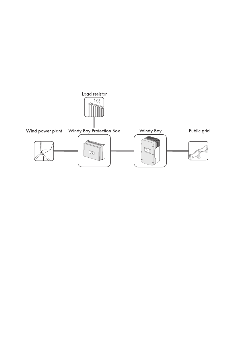
The Windy Boy is a wind energy inverter, which converts rectified current of a small wind turbine
system into AC current and feeds this energy into the power distribution grid, domestic grid or the
Sunny Island system.
Principle of a small wind turbine system with a Windy Boy
Furthermore, the Windy Boy can be used as an inverter for power conversion units based on
permanent magnet generators (hydro power system, combined heat and power plant, diesel
generator, etc.). The manufacturer of the small wind turbine system or generator should have
approved his plant for operation with this Windy Boy (also see the Windy Boy planning guidelines in
the download area at www.SMA.de/en).
When designing the PV plant, ensure that the permitted operating range of all components is
maintained at all times. In addition ensure that through the use of appropriate protective measures the
maximum permissible input voltage of the inverter is not exceeded. SMA Solar Technology AG offers
you the corresponding components, such as the Windy Boy Protection Box (overvoltage protection
for wind power inverters including the rectifier).
User Manual WB5A-6A-BA-BEN114530 7
Page 8
Safety SMA Solar Technology AG
!PV-Overvoltage!
!DISCONNECT DC!
2.2 Safety Instructions
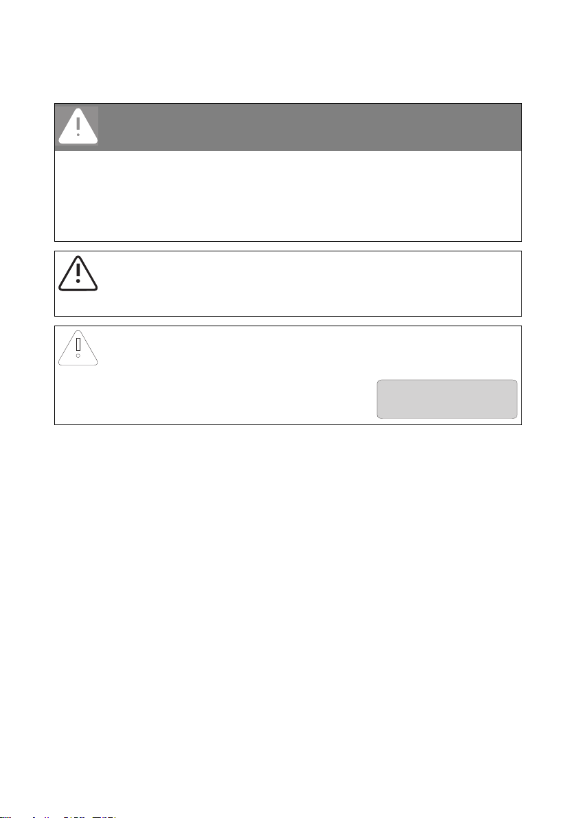
DANGER!
Electric shock caused by high voltage in the inverter
Even when no external voltage is present, there can still be high voltages in the inverter.
The following work should be carried out by electrically qualified personnel only.
• Electrical installation
• Repairs
• Modifications
CAUTION!
Risk of burns through contact with the enclosure during operation
• Only touch the enclosure lid and display during operation.
NOTICE!
Damage to the inverter through overvoltage, if the yellow LED flashes 4 times.
• Inform your installer immediately if the yellow LED
should start flashing and the following display
message appears.
8 WB5A-6A-BA-BEN114530 User Manual
Page 9

SMA Solar Technology AG Safety
2.3 Explanation of Symbols
2.3.1 Symbols on the Inverter
Symbol Explanation
Operation display.
Ground fault or varistor defective. Inform your installer.
An error has occurred. Inform your installer immediately.
You can operate the display by tapping the enclosure lid:
• Single tap: The backlight switches on or the display scrolls one
message further.
• Two taps in quick succession*: The inverter displays the device type,
the firmware version and the configured country setting
(see Section 4.2"Display Messages during Operation" (page12)).
QR-Code
You will find information on the SMA bonus program at
www.SMA-Bonus.com.
®
** for SMA bonus program
* This function is valid from firmware version 2.18.
** QR-Code is a registered trademark of DENSO WAVE INCORPORATED.
User Manual WB5A-6A-BA-BEN114530 9
Page 10

Safety SMA Solar Technology AG
2.3.2 Symbols on the Type Label
Symbol Explanation
Beware of hazardous voltage.
The inverter operates at high voltages. All work on the inverter must be
carried out by electrically qualified personnel only.
Beware of hot surface.
The inverter can become hot during operation. Avoid contact during
operation.
Observe all documentation that accompanies the inverter.
The inverter must not be disposed of together with the household waste.
Further information on disposal can be found in the enclosed installation
manual.
CE mark.
The inverter complies with the requirements of the applicable
EC guidelines.
The inverter has a transformer.
Direct current (DC).
Alternating current (AC).
Degree of protection IP65.
The inverter is protected against dust intrusion and water jets from any
angle.
RAL quality mark for solar products.
The inverter complies with the requirements of the German Institute for
Quality Assurance and Labeling.
10 WB5A-6A-BA-BEN114530 User Manual
Page 11

SMA Solar Technology AG Product Overview
3 Product Overview
Position Designation
ADisplay
BEnclosure lid
CLEDs
Green LED = Operation
Red LED = Ground fault or varistor defective
Yellow LED = Disturbance
D Ventilation grid
E Type label for the identification of the inverter via the serial number (Serial No.).
User Manual WB5A-6A-BA-BEN114530 11
Page 12

Display SMA Solar Technology AG
PowerBalancer
PowerGuard
4 Display
4.1 Operation
The display shows the current values of your plant. The displayed values are updated every
5 seconds.
You can operate the display by tapping the enclosure lid:
Single tap:
The backlight switches on or the display scrolls one message further.
2 taps in quick succession (valid from firmware version 2.18):
The inverter successively displays the device type, the firmware version, the configured country setting
and the configuration of the SMA Power Balancer.
4.2 Display Messages during Operation
After commissioning, the inverter successively displays the device type, the firmware version, the
configured country setting and the configuration of the SMA Power Balancer. If you want to view
again the display messages of the startup phase while in operation, double tap the enclosure lid
(from firmware version 2.18).
Display message Description
Inverter device type
Firmware version of internal processors
Configured country standard of inverter
(example: "GER/VDE0126-1-1")
Configuration of the SMA Power Balancer
(Example: "PowerGuard")
Upon error-free connection of the inverter to the power distribution grid, after approximately one
minute, the display starts alternating between the messages shown below. Each message appears for
5 seconds, and then the cycle restarts from the beginning.
12 WB5A-6A-BA-BEN114530 User Manual
Page 13

SMA Solar Technology AG Display
E-today 0Wh
Mode Disturbance
Disturbance
Vac-Bfr
!PV-Overvoltage!
!DISCONNECT DC!
Display message Description
Energy generated on the current day
Status message "Turbine"
Current feed-in capacity
Voltage of the small wind turbine system
After a further 5 seconds or after tapping, the current
values of the reactive power Qac and of the
displacement power factor cos φ (PF) are displayed.
Total amount of energy fed in
Total number of operating hours in feed-in operation
4.3 Display Messages during a Disturbance
In the event of a disturbance, the inverter displays the status "Disturbance" and an error message.
Inform your installer.
Display message Description
Energy generated on the current day
Status message "Disturbance"
Operating state
Error message
Measured value at the time of the disturbance
Current measured value (only displayed if a
measured value is responsible for the disturbance)
4.4 DC Overvoltage
Display message Description
The DC input voltage is too high at the inverter.
Inform your installer immediately!
User Manual WB5A-6A-BA-BEN114530 13
Page 14

LED Signals SMA Solar Technology AG
5 LED Signals
Status Description
All LEDs are on The inverter is initializing.
All LEDs are off The DC input voltage at the inverter is too low for feed-in.
All LEDs
flashing
Green LED on The inverter is feeding in to the power distribution grid.
Green LED
flashing
The inverter is in the start phase.
This flashing can have the following reasons:
• The inverter is monitoring the power distribution grid
and is waiti ng for the D C voltage t o reach a defi ned
limit so that it can begin feeding the grid.
• Operation interrupted.
• Power limitation in the inverter.
14 WB5A-6A-BA-BEN114530 User Manual
Page 15

SMA Solar Technology AG LED Signals
Status Description
Red LED on A ground fault has occurred or one of the thermally
monitored varistors on the DC input side is defective.
Inform your installer.
Yellow LED on The inverter is in the operating state
"Permanent Shutdown". This can have several causes.
Inform your installer.
Yellow LED
blinks
The inverter displays a disturbance. This can have several
causes. Inform your installer.
User Manual WB5A-6A-BA-BEN114530 15
Page 16

Visual Inspection, Maintenance and Cleaning SMA Solar Technology AG
6 Visual Inspection, Maintenance and Cleaning
Visual inspection
Check the inverter and cables for any signs of external damage. Contact your installer if you find any
damage. Do not perform any repair work yourself.
Maintenance and Cleaning
Ask your installer to check that the inverter is operating correctly at regular intervals.
If the inverter is dirty and the visibility of the operating data and operating states of the inverter is
limited, clean the enclosure lid, the display and the LEDs with a damp cloth. Do not use any corrosive
substances (e.g., solvents or abrasives) for cleaning.
16 WB5A-6A-BA-BEN114530 User Manual
Page 17

SMA Solar Technology AG Troubleshooting
7 Troubleshooting
7.1 Status Messages
Your inverter can be in various operating states. These are displayed as status messages, which can
vary according to the type of communication.
Message Description
Balanced The inverter has disconnected from the power distribution grid or
is limiting its power over a 10-minute average to 4.6 kVA
(in Italy: 6 kVA). The inverter is a part of a 3-phase system with
2 further inverters and is equipped with the SMA Power Balancer
to prevent the formation of unbalanced loads.
Derating Overtemperature in the inverter. The inverter reduces its output to
prevent overheating. To avoid unnecessary output losses, check
the plant configuration. Inform your installer.
Disturbance, disturbance Disturbance.
This message appears for safety reasons and ensures that the
inverter does not connect to the power distribution grid.
Inform your installer.
Error An error has been detected. Inform your installer.
Earthfault Measurement of the insulation resistance of the small wind turbine
system.
Grid monitoring Grid monitoring
This message appears during the startup phase before the inverter
is connected to the power distribution grid.
Of f G rid Th e in ver ter is i n "I sla nd" mod e. T his mod e is spe cia lly designed for
operation in an off-grid system.
Offset Offset adjustment of the measurement electronics.
Stop Operation interrupted.
Turbine The inverter is in the operating state "Turbine". This mode is
specially designed for operation on small wind turbine systems.
V-Const Constant voltage mode.
Waiting The connection conditions are not (yet) fulfilled.
User Manual WB5A-6A-BA-BEN114530 17
Page 18
Troubleshooting SMA Solar Technology AG
7.2 Measurement Channels
If your inverter is equipped with a communication product, then numerous measuring channels and
messages can be transmitted for diagnostics.
Measurement channel Description
Balan cer Displ ays th e current opera ting mode of th e inverter that is set to the
operating parameter "PowerBalancer".
Earthfault Insulation resistance of the small wind turbine system before
connecting to the power distribution grid.
Error Identification of the current disturbance/error.
E-total Total amount of energy fed in
Event-Cnt Number of events that have occurred
Fac Power frequency
h-On Total operating hours
h-total Total number of operating hours in feed-in operation
Iac Line current
Ipv Direct current
Is* Apparent current
Power On Total number of grid connections
Pac Generated AC power
PF* Displacement power factor cos φ
Phase The phase to which the inverter is connected.
Qac* Reactive power
Sac* Apparent power
Serial number Inverter serial number
Status Display of the current operating state
Vac Line voltage
Vpv DC input voltage
Vpv-Setpoint DC target voltage
* From firmware version 2.18
18 WB5A-6A-BA-BEN114530 User Manual
Page 19

SMA Solar Technology AG Glossary
8 Glossary
AC
Abbreviation for "alternating current".
DC
Abbreviation for "direct current".
Derating
A controlled reduction in performance, usually dependent on component temperatures.
SMA Power Balancer
The SMA Power Balancer is a serial feature of the inverter. The SMA Power Balancer prevents the
formation of an unbalanced load > 4.6 kVA (in Italy > 6 kVA) during three-phase feed-in. To this effect,
3 Windy Boys are connected via a control line to a 3-phase feed-in unit.
Varistor
The varistors protect the electronics in the inverter from atmospherically coupled energy peaks, such
as may occur when lightning strikes nearby.
User Manual WB5A-6A-BA-BEN114530 19
Page 20

Contact SMA Solar Technology AG
9 Contact
If you have technical problems, first contact your installer. We require the following information in
order to provide you with the necessary assistance:
•Inverter device type
• Inverter serial number
• Type of connected wind turbine system
• Blink code or display message of the inverter
• Optional equipment (e.g. communication products)
SMA Solar Technology AG
Sonnenallee 1
34266 Niestetal, Germany
www.SMA.de
SMA Service Line
Inverters +49 561 9522 1499
Communication: +49 561 9522 2499
Fax: +49 561 9522 4699
E‑mail: ServiceLine@SMA.de
20 WB5A-6A-BA-BEN114530 User Manual
Page 21

Page 22

Page 23

SMA Solar Technology AG Legal Restrictions
The information contained in this document is the property of SMA Solar Technology AG. Publishing its content, either partially or
in full, requires the written permission of SMA Solar Technology AG. Any internal company copying of the document for the
purposes of evaluating the product or its correct implementation is allowed and does not require permission.
Exclusion of liability
The general terms and conditions of delivery of SMA Solar Technology AG shall apply.
The content of these documents is continually checked and amended, where necessary. However, discrepancies cannot be
excluded. No guarantee is made for the completeness of these documents. The latest version is available online at www.SMA.de
or from the usual sales channels.
Guarantee or liability claims for damages of any kind are excluded if they are caused by one or more of the following:
• Damages during transportation
• Improper or inappropriate use of the product
• Operating the product in an unintended environment
• Operating the product whilst ignoring relevant, statutory safety regulations in the deployment location
• Ignoring safety warnings and instructions contained in all documents relevant to the product
• Operating the product under incorrect safety or protection conditions
• Altering the product or supplied software without authority
• The product malfunctions due to operating attached or neighboring devices beyond statutory limit values
• In case of unforeseen calamity or force majeure
The use of supplied software produced by SMA Solar Technology AG is subject to the following conditions:
• SMA Solar Technology AG rejects any liability for direct or indirect damages arising from the use of software developed by
SMA Solar Technology AG. This also applies to the provision or non-provision of support activities.
• Supplied software not developed by SMA Solar Technology AG is subject to the respective licensing and liability agreements
of the manufacturer.
SMA Factory Warranty
The current guarantee conditions come enclosed with your device. These are also available online at www.SMA.de and can be
downloaded or are available on paper from the usual sales channels if required.
Trademarks
All trademarks are recognized even if these are not marked separately. Missing designations do not mean that a product or brand
is not a registered trademark.
The Bluetooth
SMA Solar Technology AG is under license.
SMA Solar Technology AG
Sonnenallee 1
34266 Niestetal
Germany
Tel. +49 561 9522-0
Fax +49 561 9522-100
www.SMA.de
E-Mail: info@SMA.de
© 2004 to 2011 SMA Solar Technology AG. All rights reserved
®
word mark and logos are registered trademarks owned by Bluetooth SIG, Inc. and any use of such marks by
User Manual WB5A-6A-BA-BEN114530 23
Page 24

XXX4."4PMBSDPN
4."4PMBS5FDIOPMPHZ
4."4PMBS5FDIOPMPHZ"(
XXX4."EF
4.""NFSJDB--$
XXX4.""NFSJDBDPN
4."5FDIOPMPHZ"VTUSBMJB1UZ-UE
XXX4.""VTUSBMJBDPNBV
4."#FOFMVY413-
XXX4."#FOFMVYDPN
4."#FJKJOH$PNNFSDJBM$P-UE
XXX4."$IJOBDPN
4."$[FDI3FQVCMJDTSP
XXX4."$[FDIDPN
4."'SBODF4"4
XXX4."'SBODFDPN
4.")FMMBT"&
XXX4.")FMMBTDPN
4."*C©SJDB5FDOPMPHB4PMBS4-
XXX4."*CFSJDBDPN
4."*UBMJB4SM
XXX4."*UBMJBDPN
4."5FDIOPMPHZ,PSFB$P-UE
XXX4.",PSFBDPN
 Loading...