

Page 1
EN
Wind Power Inverter
WINDY BOY 3300 / 3800
User Manual
WB33_38-BA-BEN120930 | TBEN-WB33-38 | Version 3.0
Page 2

Page 3

SMA Solar Technology AG Table of Contents
Table of Contents
1 Information on this Manual. . . . . . . . . . . . . . . . . . . . . . . . . 5
1.1 Validity . . . . . . . . . . . . . . . . . . . . . . . . . . . . . . . . . . . . . . . . . . . . 5
1.2 Target Audience . . . . . . . . . . . . . . . . . . . . . . . . . . . . . . . . . . . . . 5
1.3 Additional Information . . . . . . . . . . . . . . . . . . . . . . . . . . . . . . . . 5
1.4 Symbols Used . . . . . . . . . . . . . . . . . . . . . . . . . . . . . . . . . . . . . . . 6
2 Safety . . . . . . . . . . . . . . . . . . . . . . . . . . . . . . . . . . . . . . . . . . 7
2.1 Intended Use. . . . . . . . . . . . . . . . . . . . . . . . . . . . . . . . . . . . . . . . 7
2.2 Safety Precautions. . . . . . . . . . . . . . . . . . . . . . . . . . . . . . . . . . . . 8
2.3 Explanation of Symbols . . . . . . . . . . . . . . . . . . . . . . . . . . . . . . . 9
2.3.1 Symbols on the Inverter. . . . . . . . . . . . . . . . . . . . . . . . . . . . . . . . . . . . . . . . . . .9
2.3.2 Symbols on the Type Label . . . . . . . . . . . . . . . . . . . . . . . . . . . . . . . . . . . . . . 10
3 Product Overview . . . . . . . . . . . . . . . . . . . . . . . . . . . . . . . 11
4 Display . . . . . . . . . . . . . . . . . . . . . . . . . . . . . . . . . . . . . . . . 12
4.1 Operation . . . . . . . . . . . . . . . . . . . . . . . . . . . . . . . . . . . . . . . . . 12
4.2 Display Messages during Operation . . . . . . . . . . . . . . . . . . . . 12
4.3 Display Messages during a Disturbance . . . . . . . . . . . . . . . . . 14
4.4 DC Overvoltage . . . . . . . . . . . . . . . . . . . . . . . . . . . . . . . . . . . . 14
5 LED Signals . . . . . . . . . . . . . . . . . . . . . . . . . . . . . . . . . . . . . 15
6 Visual Inspection, Maintenance and Cleaning . . . . . . . . 17
7 Troubleshooting . . . . . . . . . . . . . . . . . . . . . . . . . . . . . . . . . 18
7.1 Status Messages . . . . . . . . . . . . . . . . . . . . . . . . . . . . . . . . . . . . 18
7.2 Measurement Channels . . . . . . . . . . . . . . . . . . . . . . . . . . . . . . 19
8 Glossary . . . . . . . . . . . . . . . . . . . . . . . . . . . . . . . . . . . . . . . 20
9 Contact . . . . . . . . . . . . . . . . . . . . . . . . . . . . . . . . . . . . . . . . 21
User Manual WB33_38-BA-BEN120930 3
Page 4

Table of Contents SMA Solar Technology AG
4 WB33_38-BA-BEN120930 User Manual
Page 5

SMA Solar Technology AG Information on this Manual
1 Information on this Manual
1.1 Validity
This manual applies to the following device types:
• WB 3300
• WB 3300-IT
• WB 3300-11
• WB 3800
• WB 3800-IT
• WB 3800-11
1.2 Target Audience
This manual is intended for the operator.
1.3 Additional Information
You will find additional information on the device-specific technical data in the installation manual
provided.
You will find additional information on particular topics (e.g. description of the operating parameters)
in the download area at www.SMA.de/en.
User Manual WB33_38-BA-BEN120930 5
Page 6
Information on this Manual SMA Solar Technology AG
1.4 Symbols Used
The following types of safety precautions and general information are used in this manual:
DANGER!
DANGER indicates a hazardous situation which, if not avoided, will result in death or
serious injury.
WARNING!
WARNING indicates a safety precaution which, if not avoided, could result in death or
serious injury.
CAUTION!
CAUTION indicates a hazardous situation which, if not avoided, could result in minor or
moderate injury.
CAUTION!
NOTICE indicates a situation which, if not avoided, could result in property damage.
Information
Information provides valuable hints on the optimum installation and operation of the
product.
6 WB33_38-BA-BEN120930 User Manual
Page 7
SMA Solar Technology AG Safety
2 Safety
2.1 Intended Use
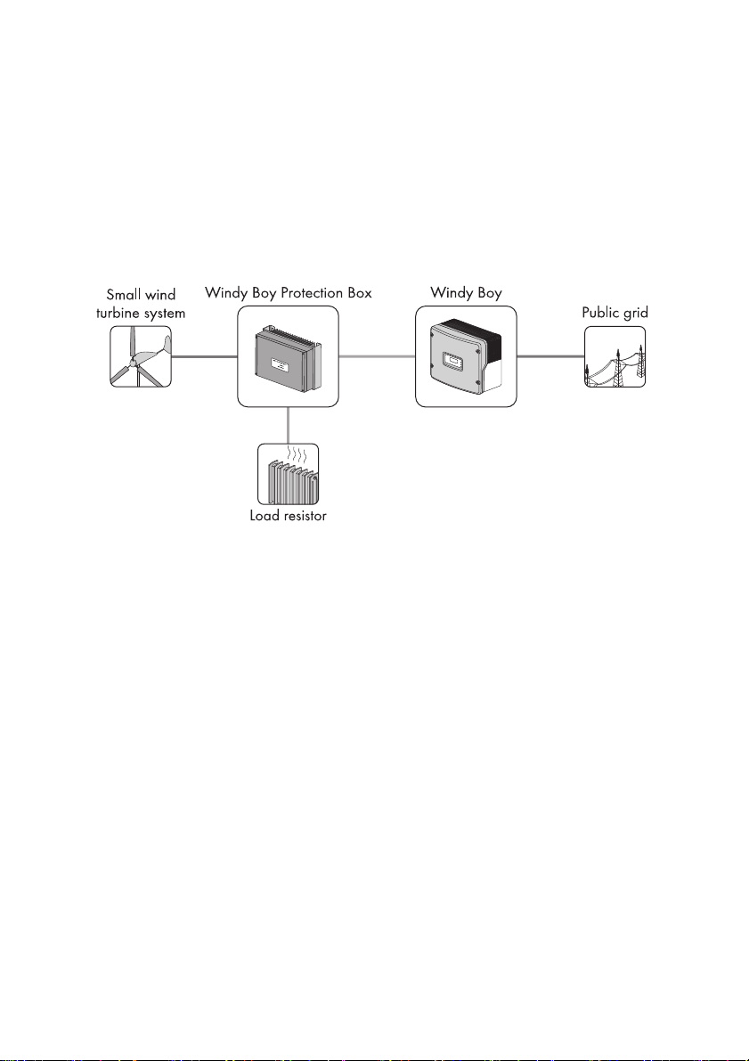
The Windy Boy is a wind energy inverter which converts the rectified current of a small wind turbine
system int o AC curren t and feeds this energy into the el ectricity grid, dom estic g rid or the Sun ny Island
system.
Principle of a small wind turbine system with a Windy Boy
Furthermore, the Windy Boy can be used as an inverter for power conversion units based on
permanent magnet generators (hydro-electric systems, combined heat and power plants, diesel
generators, etc.). The manufacturer of the small wind turbine system or generator must have
approved his plant for operation with this Windy Boy.
For safety reasons, it is not permitted to modify the product or install components that are not
explicitly recommended or distributed by SMA Solar Technology AG.
When designing the PV plant, ensure that the permitted operating range of all components is
complied with at all times. Moreover, make sure that appropriate protective measures are in place to
ensure that the maximum permissible input voltage is not exceeded. SMA Solar Technology AG
offers you the requisite components, such as the Windy Boy Protection Box (overvoltage protection
for wind power inverters, including the rectifier).
User Manual WB33_38-BA-BEN120930 7
Page 8
Safety SMA Solar Technology AG
2.2 Safety Precautions
DANGER!
Electric shock caused by high voltage in the inverter
Even when no external voltage is connected, there may still be high voltages present in the
inverter. The following work may only be carried out by trained, electrically qualified
personnel:
• Electrical installation
• Repairs
• Modifications
CAUTION!
Risk of burns through contact with the enclosure during operation
• Only touch the enclosure lid and the display during operation.
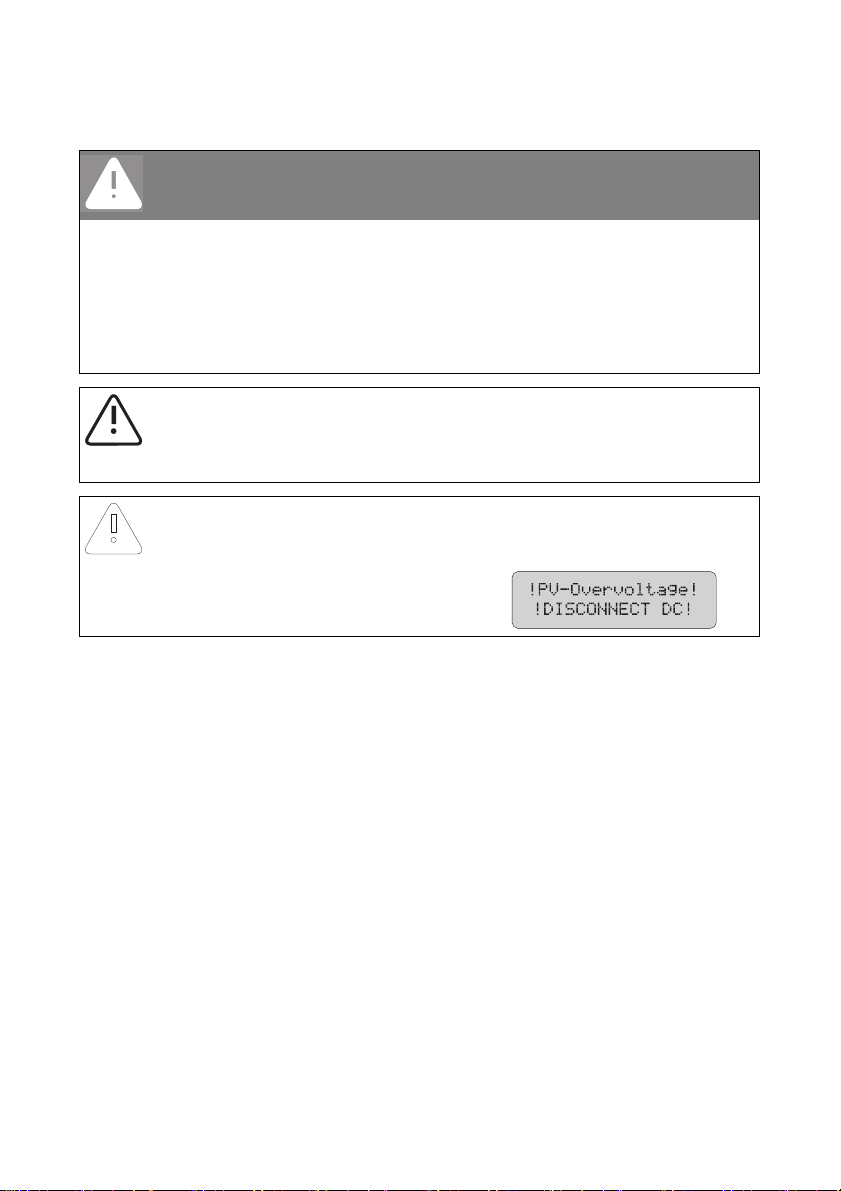
CAUTION!
Damage to the inverter through overvoltage, if the yellow LED flashes 4 times.
• Inform your installer immediately if the
yellow LED starts to flash and the
following display message appears:
8 WB33_38-BA-BEN120930 User Manual
Page 9

SMA Solar Technology AG Safety
2.3 Explanation of Symbols
2.3.1 Symbols on the Inverter
Symbol Explanation
Operation display
Earth fault or varistor defective Please inform your installer.
An error has occurred. Inform your installer immediately.
You can operate the display by tapping the enclosure lid.
• Single tap: the backlight switches on or the display scrolls one
message further.
• Double tap in quick succession*: The inverter displays the device
type, the firmware version and the configured country standard
(see Section 4.2"Display Messages during Operation" (page12)).
QR-Code
You will find information on the SMA bonus programme at
www.SMA-Bonus.com.
®
** for SMA bonus programme
* This function is valid as of firmware version 4.00.
** QR-Code is a registered trademark of DENSO WAVE INCORPORATED.
User Manual WB33_38-BA-BEN120930 9
Page 10

Safety SMA Solar Technology AG
2.3.2 Symbols on the Type Label
Symbol Explanation
Beware of dangerous electrical voltage.
The inverter operates at high voltages. All work on the inverter may only be
carried out by a trained, electrically qualified person.
Beware of hot surface.
The inverter can become hot during operation. Avoid contact during
operation.
Observe all documentation that accompanies the inverter.
The inverter must not be disposed of together with the household waste.
Further disposal information can be found in the enclosed installation
manual.
CE marking
The inverter complies with the requirements of the applicable EC directives.
The inverter has a transformer.
Direct current (DC)
Alternating current (AC)
Degree of protection IP65
The inverter is protected against dust intrusion and water jets from any
angle.
The inverter is suitable for outdoor installation.
RAL quality mark for solar products
The inverter complies with the requirements of the German Institute for
Quality Assurance and Labelling.
10 WB33_38-BA-BEN120930 User Manual
Page 11

SMA Solar Technology AG Product Overview
XXXXXXXXX
*
XX
X*
S
U
N
N
Y
B
O
Y
I
A
C
n
o
m
I
ACnom
c
o
s
ϕ
xxxxxx
A
B
C
D
E
3 Product Overview
Position Designation
AEnclosure lid
BDisplay
CLEDs
Green LED = Operation
Red LED = Earth fault or varistor defective
Yellow LED = Fault
D Ventilation grid
E Type label for the identification of the inverter via the serial number (Serial No.).
User Manual WB33_38-BA-BEN120930 11
Page 12

Display SMA Solar Technology AG
SB xxx
WRxxx
Sunny Boy xxx
WRxx
4 Display
4.1 Operation
The display shows the current values of your plant. The displayed values are updated every
5 seconds.
You can operate the display by tapping the enclosure lid.
Single tap:
The backlight is switched on. After two minutes, the backlight switches off automatically.
Double tap in quick succession (valid from firmware version 4.00):
The inverter successively displays the device type, the firmware version and the configured country
standard.
4.2 Display Messages during Operation
After commissioning, the inverter successively displays the device type, the firmware version and the
configured country standard. If you want to view the display messages of the startup phase again
while in normal operation, tap on the enclosure lid twice in quick succession
(from firmware version 4.00).
Display message Description
Inverter device type
Firmware version of internal processors
Default country standard in the inverter, example:
"VDE-AR-N4105"
12 WB33_38-BA-BEN120930 User Manual
Page 13

SMA Solar Technology AG Display
Upon error-free connection of the inverter to the electricity grid, after approximately one minute, the
display starts alternating between the messages shown below. Each message appears for five
seconds, and then the cycle restarts from the beginning.
Display message Description
Energy generated on the current day
Status message "Turbine"*
Status message "Turbine"**
Current feed-in capacity
AC line voltage of the inverter:
After a further five seconds or after tapping, the
current values of the reactive power Qac and of the
displacement power factor cos φ (PF) are
displayed.**
Total amount of energy fed in
Total number of operating hours in feed-in operation
* Applicable for WB 3300 / WB 3300-IT / WB 3800 / WB 3800-IT
** Applicable for WB 3300-11 / WB 3800-11
User Manual WB33_38-BA-BEN120930 13
Page 14

Display SMA Solar Technology AG
4.3 Display Messages during a Disturbance
In the event of a disturbance, the inverter displays the status "Disturbance" and an error message.
Please inform your installer. The following messages will be generated:
Display message Description
Energy generated on the current day
Status message "Disturbance"
Operating state
Error message
Measured value at the time of the disturbance
Current measured value (only displayed if a
measured value is responsible for the disturbance)
4.4 DC Overvoltage
Display message Description
The DC input voltage connected to the inverter is too
high.
Please inform your installer immediately.
14 WB33_38-BA-BEN120930 User Manual
Page 15

SMA Solar Technology AG LED Signals
5 LED Signals
Status Description
All LEDs are on The inverter is initializing.
All LEDs are off The DC input voltage at the inverter is too low for feed-in.
All LEDs are
flashing
Green LED is on
Green LED is
flashing
The inverter is in the startup phase.
The inverter is feeding into the electricity grid.
This flashing can be caused by:
• The inverter is monitoring the electricity grid and is
waiting for the DC voltage to reach a defined limit
so that it can begin feeding the into the network.
• Operation interrupted.
• Power limitation in the inverter.
User Manual WB33_38-BA-BEN120930 15
Page 16

LED Signals SMA Solar Technology AG
Status Description
Red LED is on An earth fault has occurred or one of the thermally
monitored varistors on the DC input side is defective.
Please inform your installer.
Yellow LED is on
Yellow LED is
flashing
The inverter is in the operating state
"Operation permanently disabled". This can have several
causes. Please inform your installer.
Th is i ndicat es a dis tur ban ce. This can have sev era l cause s.
Please inform your installer.
16 WB33_38-BA-BEN120930 User Manual
Page 17

SMA Solar Technology AG Visual Inspection, Maintenance and Cleaning
6 Visual Inspection, Maintenance and Cleaning
Visual inspection
Check the inverter and cables for any signs of external damage. Contact your installer if you find any
damage. Do not perform any repair work yourself.
Maintenance and cleaning
CAUTION!
Damage to the display by use of cleaning agents
• If the inverter is dirty, clean the enclosure lid, the display and the LEDs with clear
water and a cloth only.
User Manual WB33_38-BA-BEN120930 17
Page 18

Troubleshooting SMA Solar Technology AG
7 Troubleshooting
7.1 Status Messages
Your inverter can be in various operating states. These are displayed as status messages, which can
vary according to the type of communication.
Message Description
Derating Overtemperature in the inverter. The inverter reduces its power to
prevent overheating. To avoid unnecessary yield losses, check the
plant configuration. Please inform your installer.
Error An error has been detected. Please inform your installer.
Grid monitoring Grid monitoring
This message appears during the startup phase before the inverter
is connected to the electricity grid, and following an error.
Of f G rid Th e in ver ter is i n "I sla nd" mod e. T his mod e is spe cia lly designed for
operation in an off-grid system.
Offset Offset adjustment of the measurement electronics.
Stop Operation interrupted.
Turbine The inverter is in the operating state "Turbine". This mode is
specially designed for operation in small wind turbine systems.
V-Const Constant voltage mode.
Waiting The conditions for connecting are not (yet) fulfilled.
Warning/Disturbance Disturbance
This message appears for safety reasons and ensures that the
inverter does not connect to the electricity grid. Please inform your
installer.
18 WB33_38-BA-BEN120930 User Manual
Page 19

SMA Solar Technology AG Troubleshooting
7.2 Measurement Channels
If your inverter is equipped with a communication product, numerous measurement channels and
messages can be transmitted for diagnostics.
Measurement channel Description
Error Identification of the present disturbance/error
E-total Total amount of energy fed in
Event-Cnt Number of events that have occurred
Fac Power frequency
h-On Total operating hours
h-total Total number of operating hours in feed-in operation
Iac Line current
Ipv Direct current
Pac Generated AC power
Power On Total number of grid connections
Riso Insulation resistance of the small wind turbine system
Serial number Inverter serial number
Status Display of the current operating state
Vac Line voltage
Vpv DC input voltage
Vpv-Set DC target voltage
User Manual WB33_38-BA-BEN120930 19
Page 20

Glossary SMA Solar Technology AG
8 Glossary
AC
Abbreviation for "Alternating Current".
DC
Abbreviation for "Direct Current".
Derating
A controlled reduction in performance, usually dependent on component temperatures.
Varistor
The varistors protect the electronics in the inverter from atmospherically coupled energy peaks, such
as those that can occur when lightning strikes nearby.
20 WB33_38-BA-BEN120930 User Manual
Page 21

SMA Solar Technology AG Contact
9 Contact
If you hav e te chn ica l pr obl ems , pl eas e co nta ct y our ins tal ler f irst. The following information is required
in order to provide you with the necessary assistance:
•Inverter device type
• Inverter serial number
• Type of connected small wind turbine system
• Blink code or display message of the inverter
• Optional equipment (e.g. communication products)
SMA Solar Technology AG
Sonnenallee 1
34266 Niestetal, Germany
www.SMA.de
SMA Service Line
Inverters: +49 561 9522 1499
Communication: +49 561 9522 2499
Fax: +49 561 9522 4699
E‑Mail: ServiceLine@SMA.de
User Manual WB33_38-BA-BEN120930 21
Page 22

Page 23

SMA Solar Technology AG Legal Restrictions
The information contained in this document is the property of SMA Solar Technology AG. Publishing its content, either partially or
in full, requires the written permission of SMA Solar Technology AG. Any internal company copying of the document for the
purposes of evaluating the product or its correct implementation is allowed and does not require permission.
SMA Factory Warranty
The current warranty conditions come enclosed with your device. These are also available online at www.SMA.de and can be
downloaded or are available on paper from the usual sales channels if required.
Trademarks
All trademarks are recognized even if these are not marked separately. Missing designations do not mean that a product or brand
is not a registered trademark.
The Bluetooth
SMA Solar Technology AG is under licence.
SMA Solar Technology AG
Sonnenallee 1
34266 Niestetal
Germany
Tel. +49 561 9522-0
Fax +49 561 9522-100
www.SMA.de
E-Mail: info@SMA.de
© 2004 to 2012 SMA Solar Technology AG. All rights reserved
®
word mark and logos are registered trademarks owned by Bluetooth SIG, Inc. and any use of such marks by
User Manual WB33_38-BA-BEN120930 23
Page 24

XXX4."4PMBSDPN
4."4PMBS5FDIOPMPHZ
4."4PMBS5FDIOPMPHZ"(
XXX4."EF
4.""NFSJDB--$
XXX4.""NFSJDBDPN
4."5FDIOPMPHZ"VTUSBMJB1UZ-UE
XXX4.""VTUSBMJBDPNBV
4."#FOFMVY413-
XXX4."#FOFMVYDPN
4."#FJKJOH$PNNFSDJBM$P-UE
XXX4."$IJOBDPN
4."$[FDI3FQVCMJDTSP
XXX4."$[FDIDPN
4."'SBODF4"4
XXX4."'SBODFDPN
4.")FMMBT"&
XXX4.")FMMBTDPN
4."*C©SJDB5FDOPMPHB4PMBS4-
XXX4."*CFSJDBDPN
4."*UBMJB4SM
XXX4."*UBMJBDPN
4."5FDIOPMPHZ,PSFB$P-UE
XXX4.",PSFBDPN
 Loading...