

Page 1
CA
US
Wind power inverter
WindyBoy 3000-US/3800-US/4000-US
Addendum operating requirements
1 Notes on this addendum
1.1 Validity
This addendum does not replace the attached Sunny Boy installation guide.
• Pay attention to all operation and safety instructions listed in the Sunny Boy installation
guide.
• The Sunny Boy installation guide is delivered with the WindyBoy inverter.
This addendum describes necessary confingurations for operating a WindyBoy in combination with
a small wind turbine system.
This addendum is valid for the following Sunny Boy installation guides:
• Sunny Boy 3000-US
• Sunny Boy 3800-US
• Sunny Boy 4000-US
The listed types of inverters are referred to in the following as WindyBoy.
1.2 Target group
This addendum is for qualified personnel. Qualified personnel have received training and have
demonstrated skills and knowledge in the construction and operation of this device. Qualified
personnel are trained to deal with the dangers and hazards involved in installing electric devices.
1.3 Appropriate usage
Use the WindyBoy only in combination with a small wind turbine system having a permanet magnet
generator.
Do not operate the WindyBoy without using a rectifier with overvoltage protection like
the WindyBoyProtection Box.
Do not use the WindyBoy for purposes other than those described here. Alternative uses,
modifications to the WindyBoy or the installation of components not expressly recommended or sold
by the manufacturer void the warranty claims and operation permission.
DBWB30-40US-UUS113610 | DBUS-WB30-40US | Version 1.0
Page 2
SMA America, LLC Electrical connection
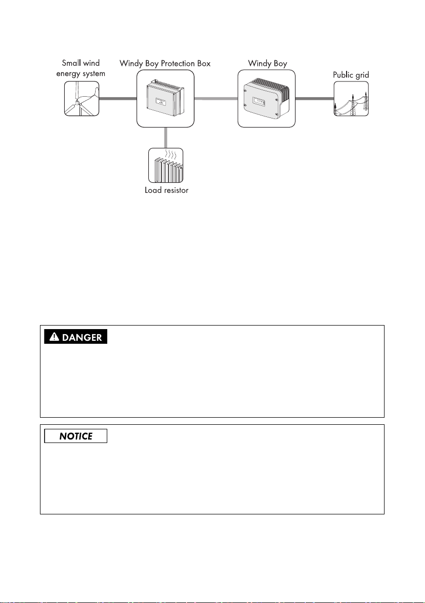
Figure1: Concept of a wind turbine system using this WindyBoy
When designing the wind turbine system, ensure that the values comply with the permitted operating
range of all components at all times.
The manufacturer of the wind turbine must have approved the turbine for use with the WindyBoy.
2 Electrical connection
2.1 Safety precautions
Risk of electric shock due to high voltages inside the WindyBoy.
Death or serious injuries will result.
• All work on the WindyBoy must only be carried out by qualified personnel.
• All work on the WindyBoy must only be done as described in this manual.
• Pay attention to all safety instructions.
Electrostatic discharges possible when components are touched.
Damage to components will result.
• Follow ESD protective provisions.
• Remove existing electrostatic charges by touching a grounded metal surface
(e.g. housing).
Addendum operating requirements DBWB30-40US-UUS113610 2/12
Page 3
SMA America, LLC Electrical connection
2.2 Load disconnection unit
Risk of electric shock due to missing protective function on the line circuit breaker.
Death or serious burn injury will result.
When a generator and a consumer are connected to the same line circuit breaker, the line circuit
breaker loses its protective function. The current from the inverter and the grid can add up to
overcurrent which is not detected by the line circuit breaker.
• Never connect loads between the inverter and the line circuit breaker without protection.
• Always install separate fuses for loads.
A screw type fuse element, e.g. D system (Diazed) or D0 system (Neozed) is not a circuit breaker,
and thus must not be used as a load disconnection unit. When disconnecting under load, the fuse
element may be damaged or its functionality may be impaired by contact burning. It only acts as
cable protection.
• Use only line circuit breakers as load disconnection units!
Detailed information
Detailed information and sample designs of a line circuit breaker can be found in the
TechnicalInformation "Line circuit breaker" in the download section of
www.SMA‑America.com.
2.3 Connecting the turbine to the rectifier
Destruction of the inverter by overvoltage.
If the voltage of the small wind turbine system exceeds the maximum input voltage of the inverter, it
can be destroyed by the overvoltage. All warranty claims become void.
• Install overvoltage protection, e.g. WindyBoy Protection Box, between the small wind turbine
system and the inverter.
For proper connection refer to the installion guides of the wind turbine system and the attached Sunny
Boy installation guide.
2.4 Connecting the rectifier to the WindyBoy
For proper connection refer to the attached installion guide of the Sunny Boy and the rectifier.
Addendum operating requirements DBWB30-40US-UUS113610 3/12
Page 4
SMA America, LLC Turbine operation
3 Turbine operation
The WindyBoy is a single phase inverter that converts DC current into AC current and feeds the
energy generated by a wind turbine system into an existing power supply system.
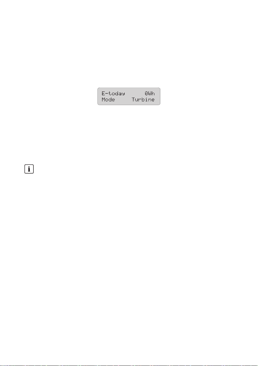
The WindyBoy inverter has a special operating mode for wind generators (see figure below). That
allows performance adjustment to the characteristic curves for generators of many different
manufacturers. In this way maximum yields can be obtained from your wind turbine system.
Figure2: Display operation mode
The mechanical power of the wind turbine is delivered to the WindyBoy in the form of a direct,
rotational-speed variable DC voltage (RPM) and current intensity (torque).
Most small wind turbine systems have a permanent magnet generator. For converting the variable
frequency AC generator voltage into DC current a rectifier like the WindyBoy Protection Box is
needed.
If a different operation mode is displayed:
• Activate the operating mode "Turbine" by using Sunny Data Control.
• If problems occur contact the SMA Serviceline.
Addendum operating requirements DBWB30-40US-UUS113610 4/12
Page 5

SMA America, LLC Turbine operation
3.1 Polynomial characteristic curve
The operation mode "Turbine" of the inverter uses a programmable output characteristic curve (output
and voltage curve) to regulate the input current depending on the generator voltage.
The polynomial characteristic curve is a programmable power curve depending on the DC input
voltage. By adapting the default polynomial characteristic curve to the small wind turbine system
being used, you can optimize the energy output of the small wind turbine system.
To optimall y adapt th e poly nomia l char acter istic curve of the inverter to the wind turbine system being
used, you can change the following parameters on the PC with the WindyBoy Setup Tool
version1.0.6 or Sunny Data Control (www.SMA-America.com). Before changing the curve
parameters, consult the manufacturer of the wind turbine system for its typical characteristics:
Parameter Description
Vpv-Start This value defines the grid connection voltage. As soon as the DC input
voltage of the inverter reaches the voltage set here, the grid monitoring of
the inverter starts up. When this occurs, the inverter carries out various
self‑tests, measurement processes and grid synchronization. When the tests
are successfully completed and the DC input voltage for the time "T-Start"
rises above "Vpv-Start", the inverter connects to the grid.
Vd cWi ndS tar t Th is v alue de fin es the s tartin g po int of the output characteristic curve. When
the DC input voltage reaches this value after grid synchronization, the
in ver ter usi ng t he outp ut char acteristic curve, starts with the load o f the wi nd
turbine and feeds into the grid.
Wind_a
0
Wind_a
1
Wind_a
2
Wind_a
3
Pmax This value defines the maximum AC output power of the inverter. The
P-Wind-Ramp This value defines the target startup of the wind turbine system. Only after
KP-Wind-Ramp This value defines the control speed of the power characteristic curve. The
This value serves to internally calculate the output characteristic curve. By
the following formula: P(U)=a0 + a1⨯U + a2⨯U2 + a3⨯U
3
inverter feeds the maximum power that has been set here into the grid.
Should the wind turbine system however produce more power than
"Pmax", this surplus power must be purged accordingly. Otherwise, there
is a risk that the inverter will be damaged by overvoltage.
connecting the inverter to the grid, the wind turbine system is not rapidly
charged but using a configurable ramp.
inverter reacts to changes in the DC input voltage by adjusting its output
power using the power characteristic curve. The higher this parameter is
set, the larger the power jump in response to the changes in the DC input
voltage. Values that are too high lead to vacillations and instability in the
system. Values that are too low delay the optimal load of the turbine and
thereby reduce the yield.
Addendum operating requirements DBWB30-40US-UUS113610 5/12
Page 6

SMA America, LLC Turbine operation
Parameter Description
KI-Wind-Ramp This value defines the control speed of the power characteristic curve. The
inverter reacts to changes in the DC input voltage by adjusting its output
power using the power characteristic curve. The higher this parameter is
set, the quicker the inverter regulates the output difference in response to
changes in DC input voltage. Values that are too high lead to vacillations
and inst abili ty in the s ystem . Values t hat ar e too l ow del ay the optimal load
of the turbine and thereby reduce the optimal yield.
T-Stop This value defines the time in which the inverter remains connected to the
grid despite low input voltage. When the DC input voltage exceeds the
minimum DC voltage, the inverter remains on the grid for the time "T-Stop"
, but does not feed in any power. During this time, it receives its own power
from the AC grid. When the DC input voltage exceeds the minimum DC
input voltage in that time, the inverter feeds the power directly into the grid.
No grid synchronization is required.
T-Start This value defines the waiting time of the inverter, before it connects to the
grid. When the tests are successfully completed and the DC input voltage
rises above the configured time "Vpv-Start", the inverter connects to the
grid. This value is prescribed by country-specific standards and may only
be changed with the permission of SMA Solar Technology.
The inverter regulates its output power according to the generator voltage. The following illustration
shows the function of a typical polynomial characteristic curve. Here, the fed-in AC power is shown
according to the DC input voltage of the inverter.
Addendum operating requirements DBWB30-40US-UUS113610 6/12
Page 7

SMA America, LLC Turbine operation
3.2 Characteristic curve operation
Characteristic curve operation
The characteristic curve of the WindyBoy only approximates the actu al c har act eristi cs o f a r eal
small wind energy system. Consult the manufacturer of your wind generator for its typical
characteristics before changing the curve parameters.
Startup Procedure
If the inverter has enough voltage and power, the startup process is displayed by means of
simultaneous lighting of the three LEDs on the inverter.
As soon as the DC input voltage defined in the parameter "Vpv-Start" is reached, the inverter starts a
number of self-tests and measurement processes and synchronizes with the grid. This operating mode
is indicated by means of the green LED blinking on the inverter.
When the tests are successfully completed and the DC input voltage is above "Vpv-Start", for the time
configured in "T-Start", the inverter connects to the grid and the green LED lights up. The inverter then
switches to characteristic curve operation, and regulates the input current according to the generator
voltage.
Characteristic Curve Operation
After the startup procedure, the inverter switches to characteristic curve operation, and regulates the
input current according to the generator voltage.
The inverter then begins to put a load on the wind turbine system and then according to the present
input voltage, takes power from the wind turbine system and feeds it into the grid. The maximum
power corresponds to the maximum AC power of the inverter. However, it can be reduced using the
"Pmax" parameter.
Shutdown Procedure
If the wind strength is so low that the DC input voltage falls below the minimum voltage of the
operating range „Turbine Mode“, the inverter ceases feeding power in to t he m ains gri d fo r th e period
defined in "T-Stop". When the DCinput voltage increases again, the inverter switches back to
characteristic curve operation.
If the DC input voltage for the time set in "T-Stop" falls below the minimum voltage of the operating
range „Turbine Mode“, the inverter will switch off.
If the DC input voltage is no longer sufficient to supply the on-board electronics with power, the
inverter deactivates immediately.
Addendum operating requirements DBWB30-40US-UUS113610 7/12
Page 8

SMA America, LLC Turbine operation
3.3 Changing the power characteristic curve
The USB service interface can only be used by opening the WindyBoy.
• Observe the safety instructions in the operating and installation manuals for your WindyBoy.
Requirement the power characteristic curve
In order to configure the WindyBoy, a DC input voltage - the minimum open-circuit voltage for
activating the operating mode "Turbine" - is needed. In addition, the WindyBoy must be
connected to the grid voltage.
Not suitable for permanent installation
Once you have finished setting the parameters, the service interface must be removed and the
WindyBoy must be closed. The connection is therefore not suitable for permanent installation.
Figure3: Connection to PC (example)
Ensure that the operating mode "Turbine" is activated.
In addition to the communications possibilities described in the attached Sunny Boy installation guide,
you can also implement a simple parameter setting using an optional "USB service interface". This
special cable allows communication between a PC and a single WindyBoy.
You need to install the WindyBoy Setup Tool version 1.0.6 or Sunny Data Control software on your
PC, which is available from the download area at www.SMA-America.com. The WindyBoy Setup
Tool and the SunnyData Control software are PC programs for direct monitoring and configuration
of your WindyBoy, which also allow visualization and logging of various system parameters.
Addendum operating requirements DBWB30-40US-UUS113610 8/12
Page 9

SMA America, LLC Commissioning
4Commissioning
Figure4: Display and LED
Object Description Explanation
A Green LED Operation
BRed LED Ground fault
C Yellow LED Disturbance
1. Check the following requirements before commissioning:
• Correct mounting and correct connection of the inverter.
• Correct layout of the line circuit breaker.
• Correct grounding of the small wind turbine system according to the manufacturer's
instructions.
• Rectifier and overvoltage protection (e.g. WindyBoy Protection Box) between the small
wind turbine system and the inverter have been installed.
2. Commission the small wind turbine system according to the instructions of the manufacturer.
☑ The green LED glows or blinks: commissioning has been successful.
or
☑ The red or yellow LED glows or blinks: an error has occurred.
Addendum operating requirements DBWB30-40US-UUS113610 9/12
Page 10

Page 11

Page 12

 Loading...