

Page 1
EN
Wind Power Inverters
WINDY BOY 3000TL / 3600TL / 4000TL / 5000TL
Installation Manual
WB3-5TL-21-IA-en-10 | IMEN-WB3-5TL-21 | Version 1.0
Page 2

Page 3

SMA Solar Technology AG Table of Contents
Table of Contents
1 Information about this document . . . . . . . . . . . . . . . . . . . . . . . . 7
2 Safety . . . . . . . . . . . . . . . . . . . . . . . . . . . . . . . . . . . . . . . . . . . . . 10
2.1 Intended Use . . . . . . . . . . . . . . . . . . . . . . . . . . . . . . . . . . . . . . . . . . . 10
2.2 Skills of Qualified Persons . . . . . . . . . . . . . . . . . . . . . . . . . . . . . . . . . 11
2.3 Safety Precautions . . . . . . . . . . . . . . . . . . . . . . . . . . . . . . . . . . . . . . . 11
3 Scope of Delivery . . . . . . . . . . . . . . . . . . . . . . . . . . . . . . . . . . . . 12
4 Product Description . . . . . . . . . . . . . . . . . . . . . . . . . . . . . . . . . . 13
4.1 Windy Boy. . . . . . . . . . . . . . . . . . . . . . . . . . . . . . . . . . . . . . . . . . . . . 13
4.2 Type Label . . . . . . . . . . . . . . . . . . . . . . . . . . . . . . . . . . . . . . . . . . . . . 15
4.3 Display. . . . . . . . . . . . . . . . . . . . . . . . . . . . . . . . . . . . . . . . . . . . . . . . 17
4.4 Bluetooth. . . . . . . . . . . . . . . . . . . . . . . . . . . . . . . . . . . . . . . . . . . . . 20
4.5 Slot for Communication Interface . . . . . . . . . . . . . . . . . . . . . . . . . . . 20
4.6 Operating Parameters . . . . . . . . . . . . . . . . . . . . . . . . . . . . . . . . . . . . 20
4.7 Slot for Multi-Function Interface . . . . . . . . . . . . . . . . . . . . . . . . . . . . . 21
4.8 Grid Management. . . . . . . . . . . . . . . . . . . . . . . . . . . . . . . . . . . . . . . 21
4.9 Varistors. . . . . . . . . . . . . . . . . . . . . . . . . . . . . . . . . . . . . . . . . . . . . . . 21
4.10 SMA Grid Guard . . . . . . . . . . . . . . . . . . . . . . . . . . . . . . . . . . . . . . . 22
5 Mounting. . . . . . . . . . . . . . . . . . . . . . . . . . . . . . . . . . . . . . . . . . . 23
5.1 Selecting the Mounting Location . . . . . . . . . . . . . . . . . . . . . . . . . . . . 23
5.2 Mounting the Inverter . . . . . . . . . . . . . . . . . . . . . . . . . . . . . . . . . . . . 26
6 Electrical Connection . . . . . . . . . . . . . . . . . . . . . . . . . . . . . . . . . 28
6.1 Safety during Electrical Connection. . . . . . . . . . . . . . . . . . . . . . . . . . 28
6.2 Overview of the Connection Area. . . . . . . . . . . . . . . . . . . . . . . . . . . 28
6.2.1 View from Below . . . . . . . . . . . . . . . . . . . . . . . . . . . . . . . . . . . . . . . 28
6.2.2 Interior View. . . . . . . . . . . . . . . . . . . . . . . . . . . . . . . . . . . . . . . . . . . 29
Installation Manual WB3-5TL-21-IA-en-10 3
Page 4

Table of Contents SMA Solar Technology AG
6.3 AC Connection . . . . . . . . . . . . . . . . . . . . . . . . . . . . . . . . . . . . . . . . . 29
6.3.1 Conditions for the AC Connection . . . . . . . . . . . . . . . . . . . . . . . . . . 29
6.3.2 Connecting the Inverter to the Power Distribution Grid . . . . . . . . . . 31
6.3.3 Additional Grounding of the Enclosure . . . . . . . . . . . . . . . . . . . . . . 34
6.4 DC Connection . . . . . . . . . . . . . . . . . . . . . . . . . . . . . . . . . . . . . . . . . 35
6.4.1 Connecting the Connection Cables to DC Connectors . . . . . . . . . . 35
6.4.2 Bridging the DC Inputs on the Inverter. . . . . . . . . . . . . . . . . . . . . . . 37
6.4.3 Connecting the Rectifier . . . . . . . . . . . . . . . . . . . . . . . . . . . . . . . . . . 38
7 Initial Start-Up. . . . . . . . . . . . . . . . . . . . . . . . . . . . . . . . . . . . . . . 42
7.1 Procedure . . . . . . . . . . . . . . . . . . . . . . . . . . . . . . . . . . . . . . . . . . . . . 42
7.2 Configuring the Country Data Set . . . . . . . . . . . . . . . . . . . . . . . . . . . 42
7.3 Setting the NetID. . . . . . . . . . . . . . . . . . . . . . . . . . . . . . . . . . . . . . . . 45
7.4 Commissioning the Inverter for the First Time. . . . . . . . . . . . . . . . . . . 46
7.5 For Italy Only: Starting the Self-Test. . . . . . . . . . . . . . . . . . . . . . . . . . 47
7.5.1 Abortion of the Self-Test . . . . . . . . . . . . . . . . . . . . . . . . . . . . . . . . . . 48
7.5.2 Restarting the Self-Test . . . . . . . . . . . . . . . . . . . . . . . . . . . . . . . . . . . 48
8 Configuration . . . . . . . . . . . . . . . . . . . . . . . . . . . . . . . . . . . . . . . 49
8.1 Changing the Display Language. . . . . . . . . . . . . . . . . . . . . . . . . . . . 49
8.2 Changing the Plant Password and Plant Time . . . . . . . . . . . . . . . . . . 50
8.3 Adapting the Polynomial Curve. . . . . . . . . . . . . . . . . . . . . . . . . . . . . 50
8.4 Setting the Deactivation Delay . . . . . . . . . . . . . . . . . . . . . . . . . . . . . 51
8.5 Changing the DC Critical Voltage for Feed-in to the
Power Distribution Grid . . . . . . . . . . . . . . . . . . . . . . . . . . . . . . . . . . . 52
8.6 Connecting the Inverter to Sunny Portal. . . . . . . . . . . . . . . . . . . . . . . 53
8.7 Setting the Operating Parameters . . . . . . . . . . . . . . . . . . . . . . . . . . . 53
9 Disconnecting the Inverter from Voltage Sources . . . . . . . . . . 54
10 Recommissioning the Inverter . . . . . . . . . . . . . . . . . . . . . . . . . . 57
4 WB3-5TL-21-IA-en-10 Installation Manual
Page 5

SMA Solar Technology AG Table of Contents
11 Troubleshooting . . . . . . . . . . . . . . . . . . . . . . . . . . . . . . . . . . . . . 59
11.1 LED Signals . . . . . . . . . . . . . . . . . . . . . . . . . . . . . . . . . . . . . . . . . . . . 59
11.2 Messages . . . . . . . . . . . . . . . . . . . . . . . . . . . . . . . . . . . . . . . . . . . . . 59
11.2.1 Event Messages . . . . . . . . . . . . . . . . . . . . . . . . . . . . . . . . . . . . . . . . 59
11.2.2 Error Messages . . . . . . . . . . . . . . . . . . . . . . . . . . . . . . . . . . . . . . . . 60
11.3 Cleaning the Inverter . . . . . . . . . . . . . . . . . . . . . . . . . . . . . . . . . . . . . 70
11.4 Checking the Small Wind Turbine System for Ground Faults . . . . . . 71
11.5 Checking the Function of the Varistors. . . . . . . . . . . . . . . . . . . . . . . . 72
11.6 Replacing the Varistors . . . . . . . . . . . . . . . . . . . . . . . . . . . . . . . . . . . 73
12 Decommissioning . . . . . . . . . . . . . . . . . . . . . . . . . . . . . . . . . . . . 75
12.1 Disassembling the Inverter . . . . . . . . . . . . . . . . . . . . . . . . . . . . . . . . . 75
12.2 Packing the Inverter . . . . . . . . . . . . . . . . . . . . . . . . . . . . . . . . . . . . . . 76
12.3 Disposing of the Inverter . . . . . . . . . . . . . . . . . . . . . . . . . . . . . . . . . . 76
13 Technical Data . . . . . . . . . . . . . . . . . . . . . . . . . . . . . . . . . . . . . . 77
13.1 DC/AC . . . . . . . . . . . . . . . . . . . . . . . . . . . . . . . . . . . . . . . . . . . . . . . 77
13.1.1 Windy Boy 3000TL . . . . . . . . . . . . . . . . . . . . . . . . . . . . . . . . . . . . . 77
13.1.2 Windy Boy 3600TL . . . . . . . . . . . . . . . . . . . . . . . . . . . . . . . . . . . . . 79
13.1.3 Windy Boy 4000TL . . . . . . . . . . . . . . . . . . . . . . . . . . . . . . . . . . . . . 81
13.1.4 Windy Boy 5000TL . . . . . . . . . . . . . . . . . . . . . . . . . . . . . . . . . . . . . 83
13.2 General Data. . . . . . . . . . . . . . . . . . . . . . . . . . . . . . . . . . . . . . . . . . . 85
13.3 Protective Devices . . . . . . . . . . . . . . . . . . . . . . . . . . . . . . . . . . . . . . . 86
13.4 Climatic Conditions . . . . . . . . . . . . . . . . . . . . . . . . . . . . . . . . . . . . . . 86
13.5 Features . . . . . . . . . . . . . . . . . . . . . . . . . . . . . . . . . . . . . . . . . . . . . . . 87
13.6 Torques . . . . . . . . . . . . . . . . . . . . . . . . . . . . . . . . . . . . . . . . . . . . . . . 87
13.7 Grounding Systems . . . . . . . . . . . . . . . . . . . . . . . . . . . . . . . . . . . . . . 87
13.8 Data Storage Capacity . . . . . . . . . . . . . . . . . . . . . . . . . . . . . . . . . . . 87
13.9 Multi-Function relay . . . . . . . . . . . . . . . . . . . . . . . . . . . . . . . . . . . . . . 88
14 Accessories . . . . . . . . . . . . . . . . . . . . . . . . . . . . . . . . . . . . . . . . . 89
15 Contact . . . . . . . . . . . . . . . . . . . . . . . . . . . . . . . . . . . . . . . . . . . . 90
Installation Manual WB3-5TL-21-IA-en-10 5
Page 6

Table of Contents SMA Solar Technology AG
6 WB3-5TL-21-IA-en-10 Installation Manual
Page 7
SMA Solar Technology AG 1 Information about this document
1 Information about this document
Validity
This document is valid for the following device types as of firmware version 2.10:
• WB 3000TL-21
• WB 3600TL-21
• WB 4000TL-21
• WB 5000TL-21
Target Group
This document is intended for qualified persons. Only qualified personnel with the appropriate skills
are allowed to perform the tasks described in this document (see Section2.2 "Skills of Qualified
Persons", page11).
Additional Information
Links to additional information can be found at www.SMA-Solar.com:
Document title Document type
Miniature Circuit-Breaker Technical information
Measured Values and Parameters Technical description
®
SMA Bluetooth ‒ SMA Bluetooth
in Practice
®
SMA Bluetooth
Wireless Technology Technical description
Wireless Technology
Technical information
Installation Manual WB3-5TL-21-IA-en-10 7
Page 8
1 Information about this document SMA Solar Technology AG
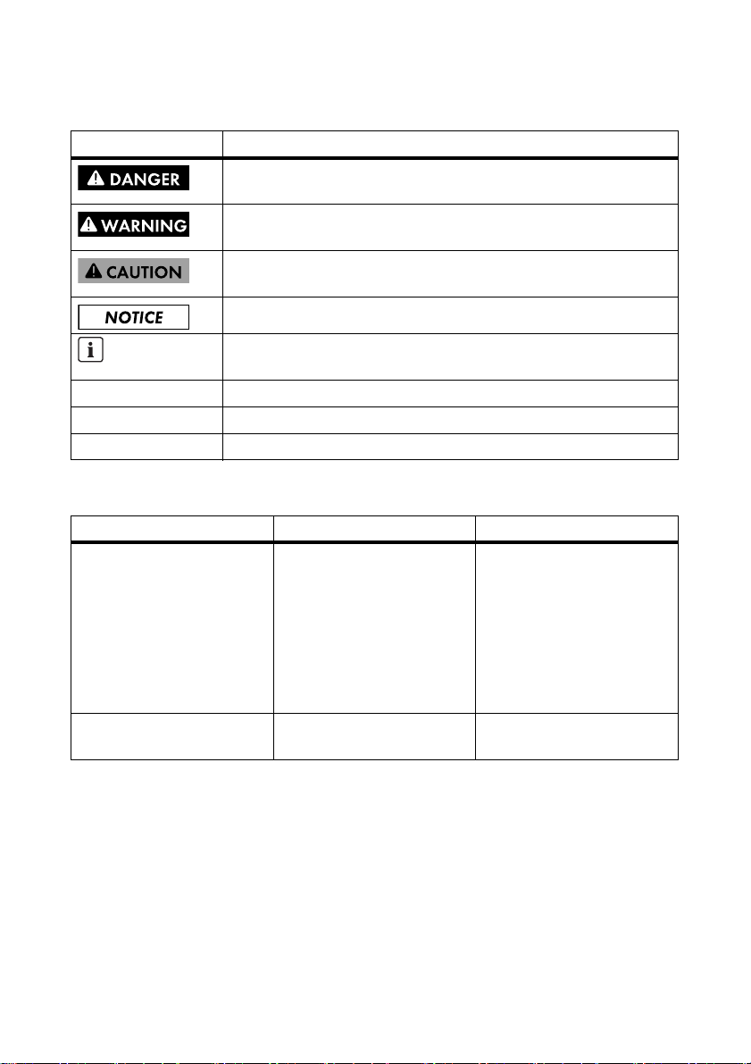
Symbols
Symbol Explanation
Indicates a hazardous situation which, if not avoided, will result in death
or serious injury
Indicates a hazardous situation which, if not avoided, can result in death
or serious injury
Indicates a hazardous situation which, if not avoided, can result in minor
or moderate injury
Indicates a situation which, if not avoided, could result in property damage
Information that is important for a specific topic or goal, but is not
safety-relevant
☐ Indicates an essential requirement for achieving a specific goal
☑ Desired result
✖ A problem that could occur
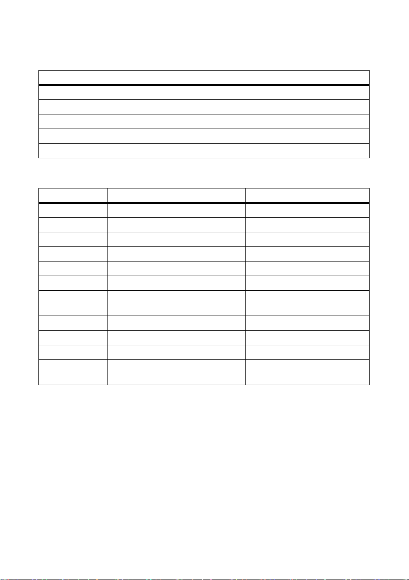
Typographies
Typography Use Example
bold •Display messages
• Parameters
• Connections
•Elements on an interface
text
• Elements to be selected
• Elements to be entered
[Button] • Button on a user interface • Select
• Select the Set country
standard parameter and
adjust the required
country data set.
[Device selection].
8 WB3-5TL-21-IA-en-10 Installation Manual
Page 9
SMA Solar Technology AG 1 Information about this document
Nomenclature
Complete designation Designation in this document
Torque Torque
Electronic Solar Switch ESS
Small wind turbine system Small wind turbine system, plant
®
SMA Bluetooth
Wireless Technology Bluetooth
Windy Boy Inverter, product
Abbreviations
Abbreviations Designation Explanation
AC Alternating Current ‒
DC Direct Current ‒
EC European Community ‒
EMC Electromagnetic Compatibility ‒
LED Light-Emitting Diode ‒
MSL Mean Sea Level ‒
NetID Network Identification Identification number for
SMA Bluetooth network
PC Personal Computer ‒
PE Protective Earth Protective conductor
SWTS Small Wind Turbine System ‒
VDE Verband der Elektrotechnik Elektronik
Informationstechnik e.V.
Association for Electrical, Electronic
and Information Technologies
Installation Manual WB3-5TL-21-IA-en-10 9
Page 10
2 Safety SMA Solar Technology AG
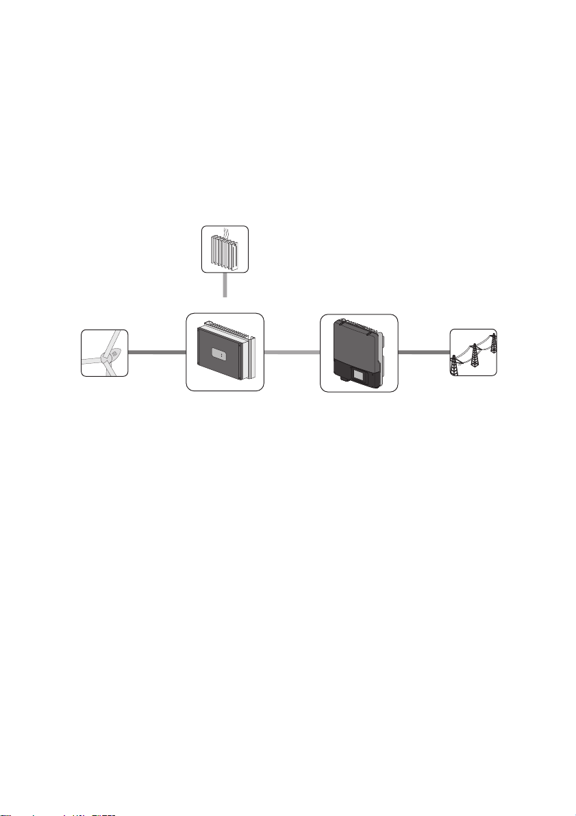
Windy Boy Protection Box
Windy Boy
power
distribution grid
Small Wind
Turbine System
Load resistor
2 Safety
2.1 Intended Use
The Windy Boy is a transformerless wind power inverter that converts the rectified alternating current
of a small wind turbine system or other energy converters based on permanent magnet electric
generators into alternating current suitable for the grid and feeds this energy into the power
distribution grid or stand-alone grid.
Figure1: Principle of a small wind turbine system with Windy Boy
The Windy Boy is suitable for indoor and outdoor use.
The Windy Boy may only be used with small wind turbine systems or with energy converters based
on permanent magnet electric generators (e.g. water energy plants, CHP plants, diesel generators).
The small wind turbine system or energy converter must be suitable for use with the Windy Boy and
ap pro ved by t he s mal l wi nd t urb ine sys tem or e ner gy c onv ert er m anuf act ure r. S MA S ola r Te chn olo gy
recommends operating Windy Boy together with a small wind turbine system without neutral
grounding.
The Windy Boy must not be connected to a direct current supply grid.
An overvoltage protection must be installed between the Windy Boy and the rectifier to limit the direct
vo lta ge. Use onl y an ove rvo lta ge p rot ect ion tha t is design ed f or the maximum power of the small wind
turbine system. SMA Solar Technology recommends using the Windy Boy Protection Box of type
50 0-1 1. I f you ar e no t using the Windy B oy P rot ect ion Box of t ype 500-11, you must install a capacity
of at least 120 μF between the Windy Boy and the rectifier. A low DC voltage ripple has a positive
effect on the electrical endurance of the inverter.
All components must remain within their permitted operating ranges at all times.
Alternative uses of the Windy Boy not expressly recommended by SMA Solar Technology AG are
not permitted.
The Windy Boy must not be connected in parallel with other inverters on the DC side.
10 WB3-5TL-21-IA-en-10 Installation Manual
Page 11

SMA Solar Technology AG 2 Safety
For safety reasons, it is not permitted to modify the product or install components that are not explicitly
recommended or distributed by SMA Solar Technology AG for this product.
Before carrying out work on the inverter and before the ESS can be removed, the small wind turbine
system must always be stopped and secured against restart. Disconnecting the inverter and removing
the ESS while the small wind turbine system is running can cause damage to the small wind turbine
system and the inverter due to the resulting rapid discharge.
• Do not mount the Windy Boy on flammable construction materials.
• Do not mount the Windy Boy near areas containing highly flammable materials.
• Do not mount the Windy Boy in potentially explosive areas.
The enclosed documentation is an integral part of this product.
• Read and observe the documentation.
• Keep the documentation in a convenient place for future reference.
2.2 Skills of Qualified Persons
The tasks described in this document must be performed by qualified persons only. Qualified persons
must have the following skills:
• Knowledge of how an inverter works and is operated
• Training in how to deal with the dangers and risks associated with installing and using electrical
devices and plants
• Training in the installation and commissioning of electrical devices and plants
• Knowledge of all applicable standards and directives
• Knowledge of and adherence to this document and all safety precautions
2.3 Safety Precautions
Electric Shock
High voltages that can cause fatal electric shocks when touched are present in the live components
of the inverter.
• Prior to pe rforming any work on the inver ter, d isconnec t it from any voltage sou rce as described
in this document (see Section 9).
Burn Hazards
Some parts of the enclosure can become hot during operation.
• Do not touch any parts other than the lower enclosure lid of the inverter during operation.
Electrostatic Discharge
By touching electronic components, you can damage or even destroy the inverter through electrostatic
discharge (ESD).
• Ground yourself before touching any components.
Installation Manual WB3-5TL-21-IA-en-10 11
Page 12
3 Scope of Delivery SMA Solar Technology AG
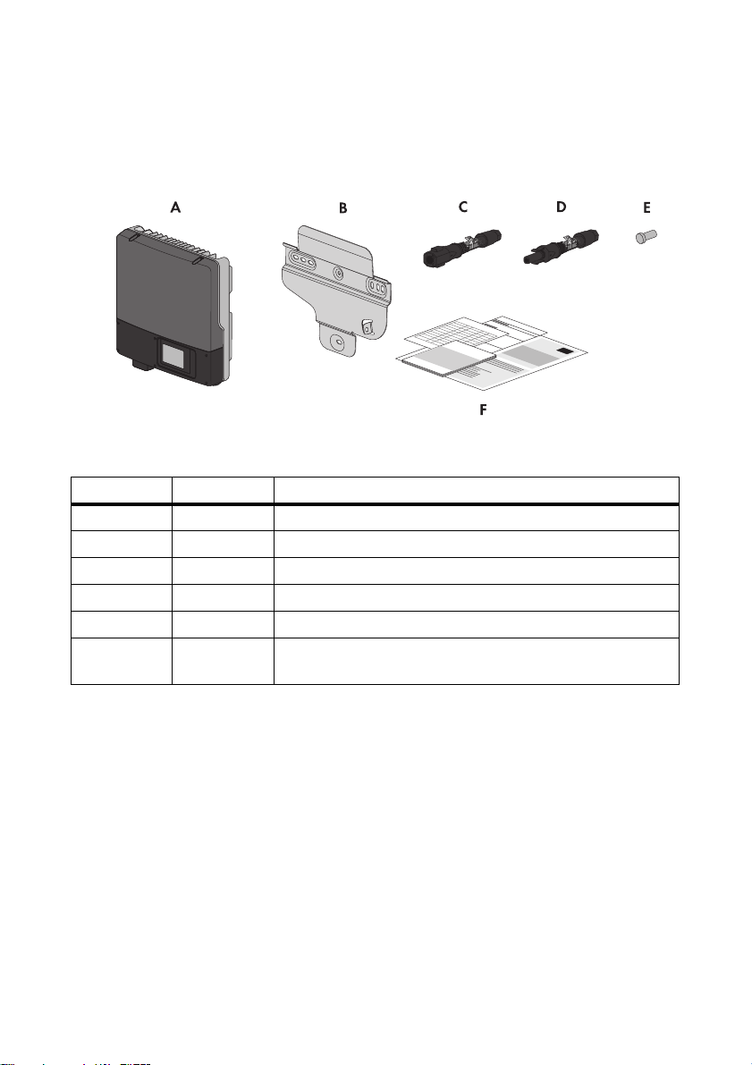
3 Scope of Delivery
Check the scope of delivery for completeness and any externally visible damage. Contact your
specialty retailer if the scope of delivery is incomplete or damaged.
Figure2: Components included in the scope of delivery
Position Quantity Description
A1Inverter
B 1 Wall mounting bracket
C4Positive DC connector
D4Negative DC connector
E8Sealing plug
F 1 Installation manual, user manual, document set with explanations
and certificates, supplementary sheet with the default settings
12 WB3-5TL-21-IA-en-10 Installation Manual
Page 13
SMA Solar Technology AG 4 Product Description
A
B
C
D
E
F
G
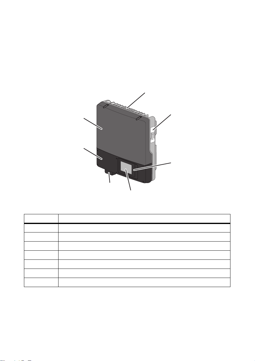
4 Product Description
4.1 Windy Boy
The Windy Boy is a transformerless wind power inverter that converts the alternating current of a small
wind turbine system into alternating current suitable for the grid and feeds this energy into the power
distribution grid or stand-alone grid.
Figure3: Design of the Windy Boy
Position Description
A Cooling fins
B Type label
CLEDs
DDisplay
E Electronic Solar Switch (ESS)
FLower enclosure lid
G Upper enclosure lid
Installation Manual WB3-5TL-21-IA-en-10 13
Page 14
4 Product Description SMA Solar Technology AG
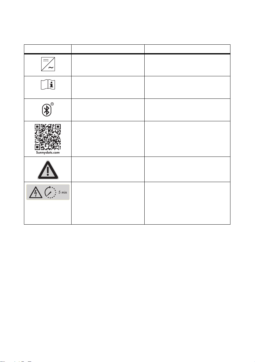
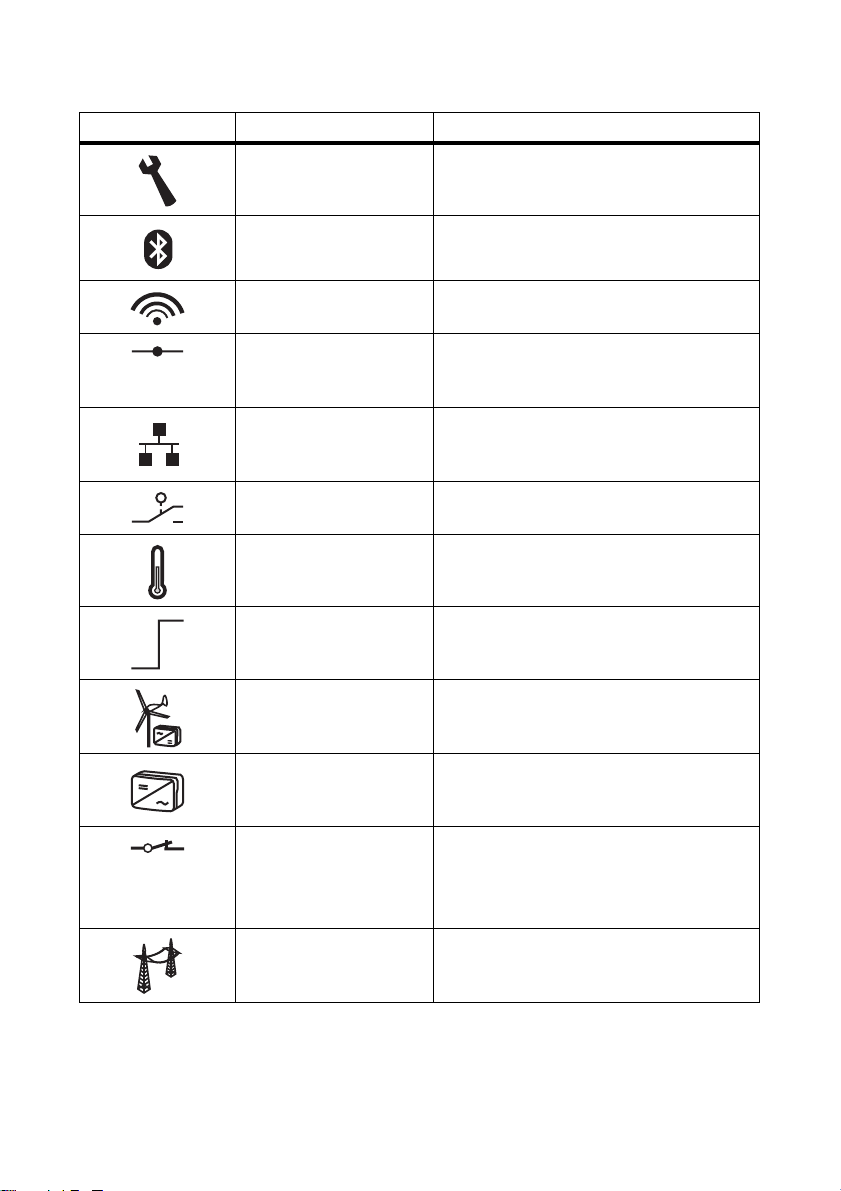
Symbols on the inverter
Symbol Description Explanation
Inverter This symbol defines the function of the
green LED. The green LED indicates the
operating state of the inverter.
Observe documentation This symbol defines the function of the
red LED. The red LED indicates an error.
Read this document to remedy the error.
Bluetooth This symbol defines the function of the
bl ue L ED. The blu e LE D in dic ate s th at the
Bluetooth communication is enabled.
QR Code
®
Danger If a second protective conductor is
The QR Code® refers to the SMA bonus
program (for information on this, see
www.SMA-Bonus.com).
required, also ground the enclosure (see
Section 6.3.3).
Danger to life due to high
voltages in the inverter; observe
waiting time.
High voltages that can cause fatal
electric shocks are present in the live
components of the inverter. Disconnect
the inverter from any voltage sources
before performing any work on it
(see Section 9).
14 WB3-5TL-21-IA-en-10 Installation Manual
Page 15
SMA Solar Technology AG 4 Product Description
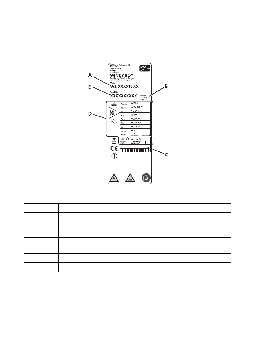
4.2 Type Label
The type label provides a unique identification of the inverter. The type label is on the right-hand side
of the enclosure.
Figure4: Layout of the type label
Position Description Explanation
A Model Inverter device type
BDate of manufacture Inverter manufacture date
(year-month-day)
C Additional information Field for additional information, e.g.
standard information
D Device-specific characteristics ‒
E Serial No. Inverter serial number
You will require the information on the type label to use the inverter safely and when seeking customer
support from the SMA Service Line. The type label must be permanently affixed to the inverter.
Installation Manual WB3-5TL-21-IA-en-10 15
Page 16
4 Product Description SMA Solar Technology AG
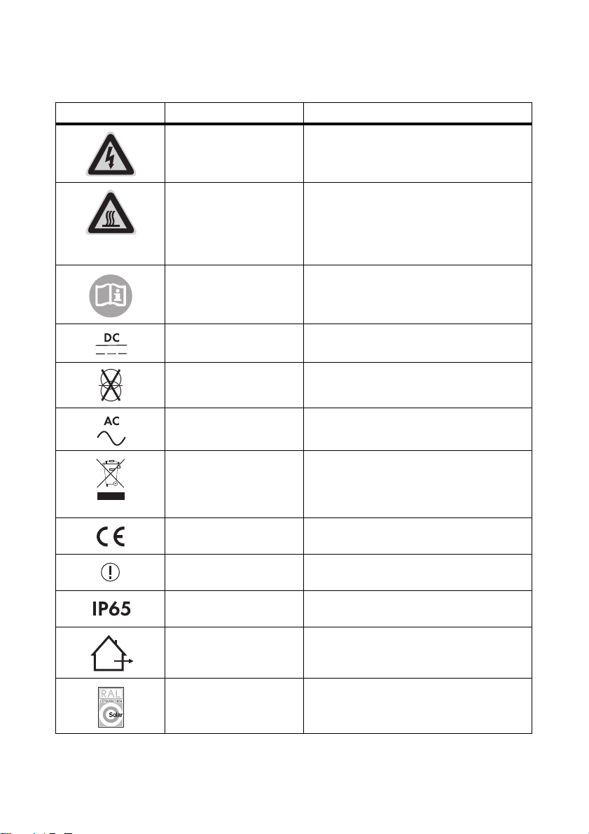
Symbols on the type label
Symbol Description Explanation
Danger to life due to high
voltages.
The product operates at high voltages.
All work on the inverter must be carried out by
qualified persons only.
Risk of burns from hot
surfaces
The product can become hot during operation.
Avoid contact during operation. Allow the
product to cool down sufficiently before
carrying out any work. Wear personal
protective equipment such as safety gloves.
Observe documentation Observe all documentation that is supplied
with the product.
DC Direct current
Without transformer The product does not have a transformer.
AC Alternating current
WEEE designation Do not dispose of the product together with the
household waste but in accordance with the
locally applicable disposal regulations for
electronic waste.
CE marking The product complies with the requirements of
the applicable EC directives.
Device class ID The product is equipped with a wireless
component and complies with device class 2.
Degree of protection The product is protected against dust intrusion
and water jets from any angle.
Outdoor The product is suitable for outdoor installation.
RAL quality mark for solar
products
The product complies with the requirements of
the German Institute for Quality Assurance
and Certification.
16 WB3-5TL-21-IA-en-10 Installation Manual
Page 17
SMA Solar Technology AG 4 Product Description
Symbol Description Explanation
Certified safety The product is VDE-tested and complies with
the requirements of the German Equipment
and Product Safety Act.
C-Tick The product complies with the requirements of
the applicable Australian EMC standards.
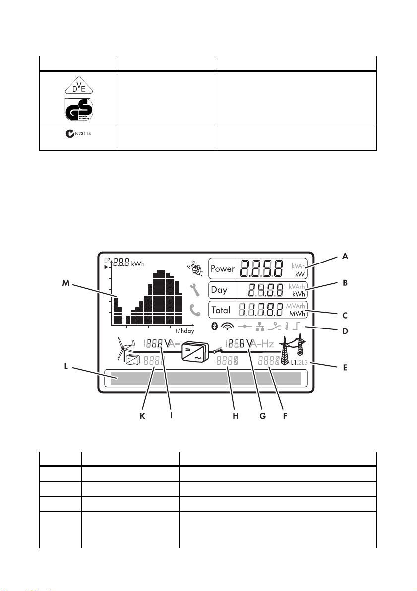
4.3 Display
The display shows the current operating data of the inverter (e.g. current power, daily energy, total
energy) as well as events or errors. The power and energy are displayed as bars in the diagram.
There is a slot for an SD card on the left edge of the display enclosure. You can use the SD card to
carry out an inverter firmware update, for example (for information on firmware updates with an
SD card see the technical description "Firmware Update with SD Card" at www.SMA-Solar.com).
Figure5: Display layout (example)
Position Description Explanation
A Power Current power
B Day Daily energy
C Total Displays the total amount of energy fed in up until now
D Active functions The different symbols indicate which functions for
communication, grid management or temperature
derating are enabled or active.
Installation Manual WB3-5TL-21-IA-en-10 17
Page 18
4 Product Description SMA Solar Technology AG
Position Description Explanation
E Line conductor Indicates which line conductor the displayed values are
assigned to.
F Event number relating to the
power distribution grid
G Output voltage/
output current
H Event number relating to the
Event number of errors relating to the power distribution
grid
Displays output voltage and output current of a line
conductor in alternation
Event number of errors relating to the inverter
inverter
IInput voltage/
input current
K Event number relating to the
small wind turbine system
Displays input voltage and input current of one input in
alternation
Event number of errors relating to the small wind turbine
system
L Text line Displays the event message or error message
M Power and yield curve Changes in power over the last 16 feed-in hours or the
energy yields over the last 16 days
• In order to switch between the displays, tap once
on the enclosure lid
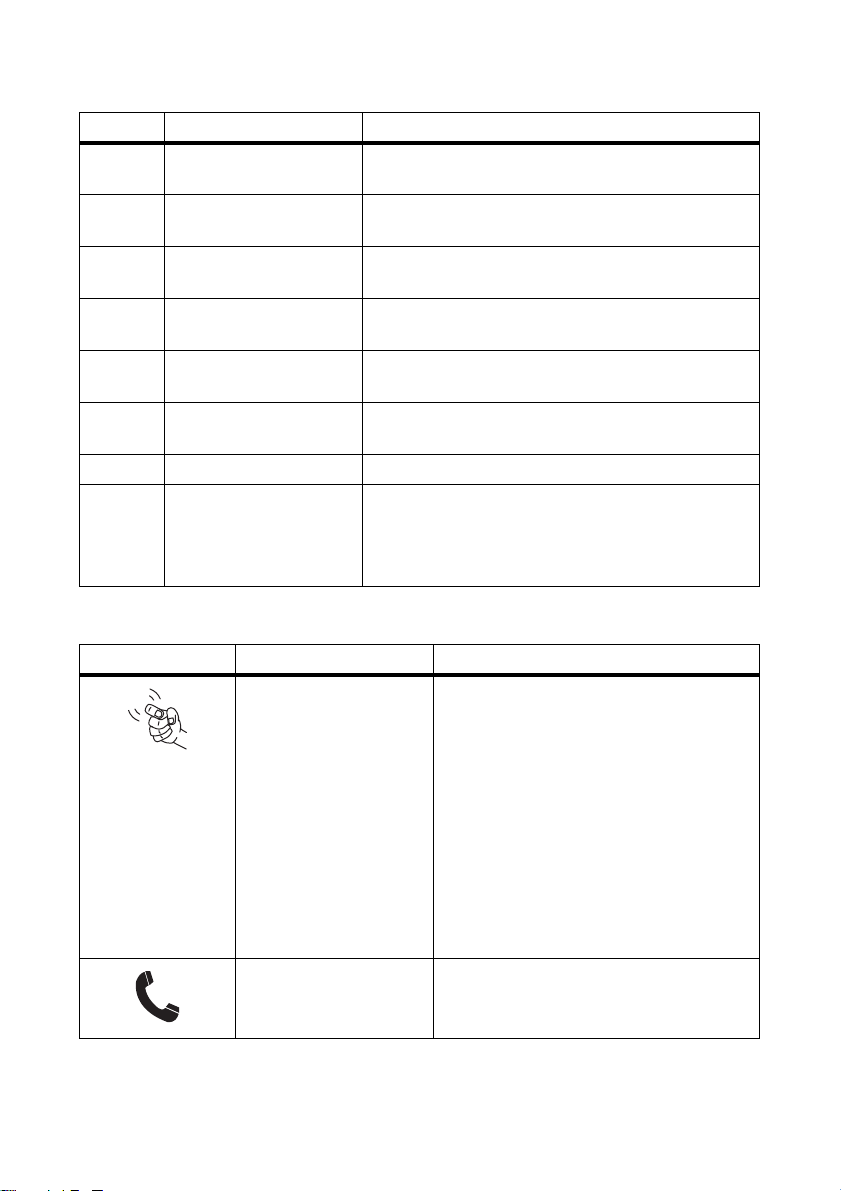
Symbols on the display
Symbol Description Explanation
Tapping You can operate the display by tapping on the
enclosure lid:
• Tapping once: to activate the backlight,
to scroll to the next text line, to switch
between the power graphs of the last
16 feed-in hours and the energy yields of
the last 16 days.
• Tapping twice: the display shows, in
succession, the firmware version, the
serial number or designation of the
inverter, NetID, the configured country
data set and display language.
Telephone receiver Indicates that an error cannot be rectified on
site
• Contact the SMA Service Line.
18 WB3-5TL-21-IA-en-10 Installation Manual
Page 19
SMA Solar Technology AG 4 Product Description
Symbol Description Explanation
Wrench Indicates that an error can be rectified on site
Bluetooth Indicates that an active Bluetooth conne cti on is
established
Bluetooth connection
quality
Indicates the quality of the Bluetooth
connection to other Bluetooth devices
Speedwire If a Speedwire data module is installed in the
inverter, this symbol indicates that there is a
connection to a network.
Webconnect function If a Webconnect data module is installed in the
inverter, this symbol indicates that it is possible
to connect to the Sunny Portal.
Multi-function relay Indicates that the multi-function relay is active
Thermometer Indicates that the power of the inverter is
limited due to excessive temperature
Power limitation Indicates that the external active power
limitation via the plant control is active
Small wind turbine system
‒
with rectifier
Inverter ‒
Grid relay A closed grid r elay i ndicates that t he inv erter is
feeding into the power distribution grid.
An open grid relay shows that the inverter is
disconnected from the power distribution grid.
Power distribution grid ‒
Installation Manual WB3-5TL-21-IA-en-10 19
Page 20

4 Product Description SMA Solar Technology AG
4.4 Bluetooth
The inverter is equipped as standard with a Bluetooth interface and can communicate with special
SMA communication products or other inverters (for information on supported products, see
www.SMA-Solar.com).
If you would like to communicate via Bluetooth, you can protect the inverter with one plant password
for the user and one plant password for the installer.
All inverters are delivered with a standard plant password for the user (0000) and a standard plant
password for the installer (1111). To protect the plant from unauthorized access, you must change
the plant passwords using Sunny Explorer (for information on changing the plant password, refer to
the Sunny Explorer help).
If you do not wish to communicate via Bluetooth, deactivate the Bluetooth communication
(see Section7.3 "Setting the NetID", page45).
4.5 Slot for Communication Interface
The inverter can optionally be fitted with an extra communication interface (e.g. RS485).
This communication interface enables the inverter to communicate with special SMA communication
products (for information on supported products, see www.SMA-Solar.com). The communication
interface can be retrofitted or installed by default with the respective order.
Depending on the type of communication, RS485, Bluetooth, or Speedwire, the parameters and
messages are displayed differently on the communication products.
Example: How the country data set parameter is displayed
• For communication with RS485: CntrySet parameter
• For communication with Bluetooth or Speedwire: Set country standard parameter
4.6 Operating Parameters
Various operating parameters control the functionality of the inverter. You can only adjust all
operating parameters of the inverter, excluding the country data set, using an SMA communication
product (see Section 8.7). You can adjust the country data set before commissioning or within the first
ten feed-in hours via two rotary switches in the inverter (see Section 7.2).
20 WB3-5TL-21-IA-en-10 Installation Manual
Page 21

SMA Solar Technology AG 4 Product Description
4.7 Slot for Multi-Function Interface
The inverter has a slot for a multi-function interface. This slot is designed to connect a simple
multi-function relay, an SMA Power Control Module, or a fan retrofit kit. The multi-function interface
can be retrofitted or installed by default with the respective order.
Multi-Function Relay
You can configure the multi-function relay for various operating modes. The multi-function relay is
used, for example, to switch error indicators on or off (for information on installation and
configuration, see installation manual of the multi-function relay).
SMA Power Control Module
The SMA Power Control Module enables the inverter to implement grid management and is equipped
with an additional multi-function relay (for information on installation and configuration, see the
SMA Power Control Module installation manual).
Fan Retrofit Kit
The fan retrofit kit is used for additional inverter cooling at high ambient temperatures and also has a
multi-function relay (for information on installation and configuration, see the fan retrofit kit installation
manual). The fan retrofit kit and the SMA Power Control Module cannot be operated in parallel.
4.8 Grid Management
The inverter is equipped with grid management functions.
Depending on the requirements of the grid operator, you can activate and configure the functions
(e.g. provision of reactive power, active power limitation) via operating parameters (for information
on the functions and operating parameters, see the Technical Description "Measured Values and
Parameters" at www.SMA-Solar.com).
4.9 Varistors
Varistors are voltage-dependent resistors that protect the inverters against overvoltage. The inverter is
equipped with thermally monitored varistors.
Varistors can become worn and lose their protective function with age or repeated strain as a result
of overvoltage. The inverter detects if one of the varistors is defective and displays an error message.
The varistors are specially manufactured for use in the inverter and are not commercially available.
You must order new varistors directly from SMA Solar Technology AG.
Installation Manual WB3-5TL-21-IA-en-10 21
Page 22

4 Product Description SMA Solar Technology AG
4.10 SMA Grid Guard
SMA Grid Guard acts as an automatic disconnection device between a grid-parallel generator
(e.g. a PV plant or small wind turbine system) and the power distribution grid.
Furthermore, SMA Grid Guard is a grid monitoring concept which detects errors by permanently
monitoring grid impedance, line voltage and power frequency. For example, SMA Grid Guard
detects when a stand-alone grid is formed and immediately disconnects the inverter from the power
distribution grid.
In some countries, the connection conditions require a device which protects grid-relevant operating
parameters against unpermitted changes. SMA Grid Guard assumes this function and protects the
setting of the country data set after the first 10 feed-in hours. After the first 10 feed-in hours the country
data set can only be changed using a communication product and after a personal access code has
been entered, the SMA Grid Guard code. You can obtain the SMA Grid Guard code from
SMA Solar Technology AG (for application for the SMA Grid Guard code, see certificate
"Application for SMA Grid Guard-Code" at www.SMA-Solar.com).
22 WB3-5TL-21-IA-en-10 Installation Manual
Page 23
SMA Solar Technology AG 5 Mounting
5 Mounting
5.1 Selecting the Mounting Location
Requirements for the mounting location:
Danger to life due to fire or explosion
Despite careful construction, electrical devices can cause fires.
• Do not mount the inverter on flammable construction materials.
• Do not mount the inverter in areas where highly flammable materials are stored.
• Do not mount the inverter in a potentially explosive atmosphere.
☐ The mounting location must be inaccessible to children.
☐ A solid foundation must be available for mounting, e.g. concrete or masonry. When mounted
on plasterboard or similar materials in a living area, the inverter will develop audible vibrations
during operation, which could be considered disturbing.
☐ The mounting location must be suitable for the weight and dimensions of the inverter
(see Section13 "Technical Data", page77).
☐ The mounting location must be easily and safely accessible at all times without the use of
additional aids being necessary, e.g., scaffolding or lifting platforms. Non-fulfillment of these
criteria may restrict servicing.
☐ The mounting location must not be exposed to direct solar irradiation. Direct solar irradiation
can overheat the inverter. As a result, the inverter reduces its power output.
☐ Climatic conditions must be met (see Section13 "Technical Data", page77).
☐ The ambient temperature must be below 40°C to ensure the optimal operation of the inverter.
Installation Manual WB3-5TL-21-IA-en-10 23
Page 24
5 Mounting SMA Solar Technology AG
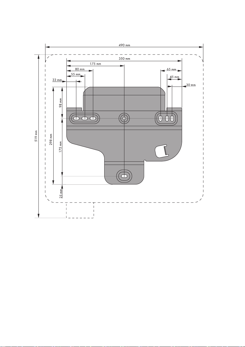
Dimensions for wall mounting:
Figure6: Wall mounting bracket dimensioning
24 WB3-5TL-21-IA-en-10 Installation Manual
Page 25
SMA Solar Technology AG 5 Mounting
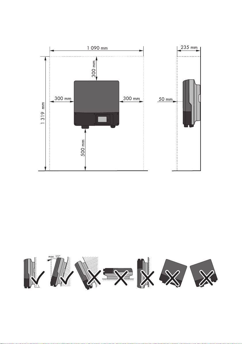
Observe recommended clearances:
Figure7: Recommended clearances
• Observe minimum clearances to the walls as well as to other inverters or objects.
This ensures adequate heat dissipation and sufficient space to remove the ESS.
• If multiple inverters are mounted in areas with high ambient temperatures, increase the
clearances between the inverters and ensure sufficient fresh-air supply.
☑ This prevents a reduction in inverter power as a result of high temperatures (for details
on temperature derating, see the Technical Information "Temperature Derating"
at www.SMA-Solar.com).
Observe permitted mounting position:
Figure8: Permitted and prohibited mounting positions
Installation Manual WB3-5TL-21-IA-en-10 25
Page 26
5 Mounting SMA Solar Technology AG
• Mount t he inv erter in a pe rmitt ed mou nting posit ion. T he dis play should be mounted at eye level.
☑ Mounting the inverter in a permissible position will ensure that no moisture can penetr ate the
inverter.
☑ By mounting the device at eye level, display messages and LED signals can be read without
difficulty.
5.2 Mounting the Inverter
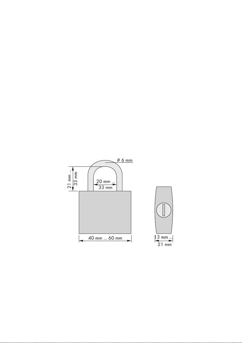
Anti-theft device:
You can protect the inverter from theft with a padlock. The padlock locks the inverter to the wall
mounting bracket.
The device must meet the following requirements:
☐ The material must be resistant to corrosion.
☐ The lock shackle must be hardened.
☐The lock cylinder must be secured.
☐ If it is mounted outdoors, the padlock must be weather-proof.
☐ The function must be guaranteed for the electrical endurance of the inverter.
Figure9: Dimensions of the padlock for the anti-theft device
Additionally required mounting material (not included in the scope of delivery):
☐ 3 screws (minimum diameter 6 mm) that are suitable for the foundation
☐ 3 washers (minimum external diameter 18 mm) that are suitable for the screws
☐ 3 screw anchors that are suitable for the foundation
☐ If the inverter is to be protected against theft, 1 padlock
1. Ensure that there are no lines laid in the wall which could be damaged when drilling.
26 WB3-5TL-21-IA-en-10 Installation Manual
Page 27
SMA Solar Technology AG 5 Mounting
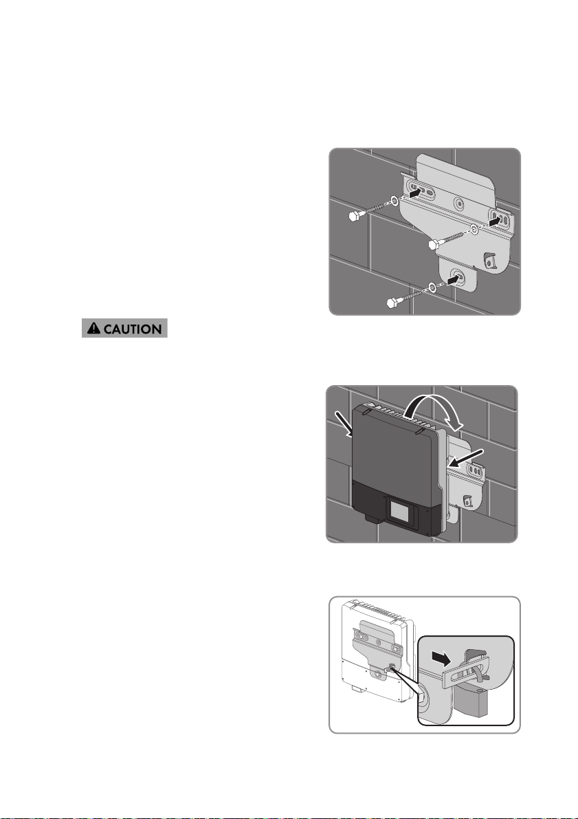
2. Mark the position of the drill holes using the wall mounting bracket. Use at least two holes on
the left-hand and right-hand side and the lower hole in the wall mounting bracket.
Tip: When mounting on a post, use the upper and lower central holes.
3. Drill the holes and insert the screw anchors.
4. Secure the wall mounting bracket horizontally to
the wall using screws and washers.
5.
Risk of injury when hanging the inverter in the wall mounting bracket
• Keep in mind the weight of the inverter (see Section13 "Technical Data", page77).
• Hang the inverter in the wall mounting
bracket. Use the recessed grips at the side
and transport the inverter in a horizontal
position.
6. Ensure that the inverter is securely seated.
7. To protect the inverter from theft, attach a padlock:
• Place the shackle of the padlock through the
metal lug on the wall mounting bracket and
through the lug on the rear of the inverter.
As you do so, move the shackle outward from
the center of the inverter.
• Close the shackle.
Installation Manual WB3-5TL-21-IA-en-10 27
Page 28
6 Electrical Connection SMA Solar Technology AG
A B
C
D
6 Electrical Connection
6.1 Safety during Electrical Connection
Electric Shock
High voltages that can cause fatal electric shocks when touched are present in the live components
of the inverter.
• Prior to pe rforming any work on the inver ter, d isconnec t it from any voltage sou rce as described
in this document (see Section 9).
Electrostatic Discharge
Touching electronic components can cause damage to or destroy the inverter through electrostatic
discharge.
• Ground yourself before touching any components.
6.2 Overview of the Connection Area
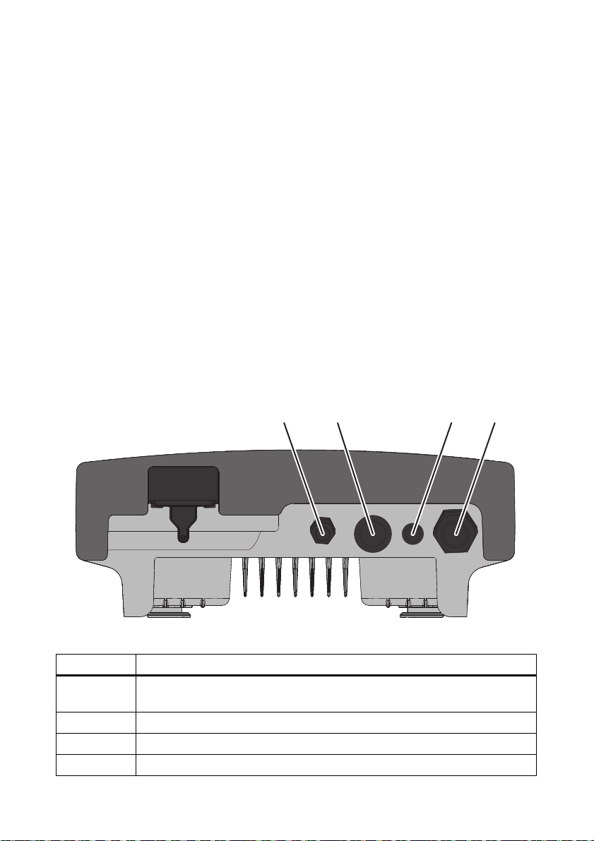
6.2.1 View from Below
Figure10: Enclosure openings at the bottom of the inverter
Position Description
A Cable gland M20x1.5 for connection to the multi-function interface or connection
of the fan retrofit kit
B Enclosure opening with filler-plug for connection to the communication interface
C Enclosure opening with filler-plug for connection to the communication interface
D Cable gland M32x1.5 for connection to the power distribution grid
28 WB3-5TL-21-IA-en-10 Installation Manual
Page 29

SMA Solar Technology AG 6 Electrical Connection
B
A CDEF
G
H
6.2.2 Interior View
Figure11: Connection areas in the interior of the inverter
Position Description
A 2 positive and 2 negative DC connectors, input A
B Jack for plugging in the ESS
C 2 positive and 2 negative DC connectors, input B
D Jack for connecting the multi-function interface
E Jack for connecting the communication interface
F Connecting terminal plate for connecting the AC cable
G Installation location for retrofitted fan
H Ground terminal for additional grounding of the inverter
6.3 AC Connection
6.3.1 Conditions for the AC Connection
Cable requirements:
☐ External diameter: 12 mm to 21 mm
☐ Maximum wire size: maximal 10 mm²
☐ Stripping length: 12 mm
Installation Manual WB3-5TL-21-IA-en-10 29
Page 30

6 Electrical Connection SMA Solar Technology AG
☐ The cable must be dimensioned in accordance with the local and national directives for the
dimensioning of cables. The requirements for the minimum wire size derive from these directives.
Influencing factors for cable dimensioning are, among others, the following: nominal AC
current, type of cable, routing method, cable bundling, ambient temperature, and maximum
desired line losses.
Switch-disconnector and cable protection:
Damage to the inverter due to the use of screw-type fuses as load disconnection units
Screw-type fuses (e.g. DIAZED fuses or NEOZED fuses) are not switch-disconnectors
• Do not use screw-type fuses as load disconnection units.
• Use a switch-disconnector or miniature circuit-breaker as a load disconnection unit
(for information and examples for designing, see the Technical Information "Miniature
Circuit-Breaker" at www.SMA-Solar.com).
• In plants with multiple inverters, protect every inverter with a separate miniature circuit-breaker.
Observe the maximum permissible fuse protection (see Section13 "Technical Data", page77).
That prevents residual voltage being present at the corresponding cable after disconnection.
• Loads installed between the inverter and the miniature circuit-breaker must be protected
separately.
Residual-current device:
• If an external residual-current device is prescribed, install a residual-current device that trips at
a residual current of 100 mA or higher (for information on choice of residual-current devices,
see the Technical Information "Criteria for Selecting a Residual-Current Device" at
www.SMA-Solar.com).
Protective conductor monitoring:
The inverter is equipped with protective conductor monitoring that detects if the protective conductor
is not connected and if this is the case, disconnects the inverter from the power distribution grid.
Depending on the installation site and grounding system, it may be advisable to deactivate the
protective conductor monitoring. Ask your grid operator or SMA Solar Technology AG to advise.
• To ensure safety according to IEC 62109 when the protective conductor monitoring is
deactivated, connect a protective conductor to the connecting terminal plate for the AC cable
(minimum cross-section: 10 mm², copper wire).
or
Connect a second protective conductor with the same wire size as the original protective
conductor (see Section6.3.3 "Additional Grounding of the Enclosure", page34). This prevents
touch current if the original protective conductor fails.
Connection of a second protective conductor
In some countries a second protective conductor is required as a matter of principle.
In each case, observe the local applicable regulations.
30 WB3-5TL-21-IA-en-10 Installation Manual
Page 31

SMA Solar Technology AG 6 Electrical Connection
1
2
6.3.2 Connecting the Inverter to the Power Distribution Grid
Requirements:
☐ The connection requirements of the grid operator must be met.
☐ The line voltage must be within the permissible range. The exact operating range of the inverter
is specified in the operating parameters (see the Technical Description "Measured Values and
Parameters" at www.SMA-Solar.com).
1. Stop the small wind turbine system and secure against restart.
2. Disconnect the miniature circuit-breaker and secure against re-connection.
3. Remove the ESS.
4. Loosen all six screws of the lower enclosure lid
us ing an Allen ke y (AF 3) and remov e the enclosur e
lid.
5. Flip the display up to have more space to make the
connection. Loosen the screw on the display to do
this.
☑ The display clicks into place.
Installation Manual WB3-5TL-21-IA-en-10 31
Page 32

6 Electrical Connection SMA Solar Technology AG
6. If the diameter of the AC cable is between 15 mm and 21 mm, remove the insert from the seal
in the AC cable gland:
• Unscrew the swivel nut of the AC cable gland.
• Remove the insert in the seal of the AC cable
gland.
• Screw the swivel nut a little way onto the AC cable gland. Do not fully tighten the swivel nut.
7. Strip the AC cable insulation.
8. Shorten L and N by 5 mm each.
9. Strip 12 mm of the L, N, and PE insulation each.
10. Route the AC cable into the inverter through the cable gland. If necessary, slightly loosen the
swivel nut of the cable gland.
11. Push the safety levers of the connecting terminal
plate for the AC cable right up to the stop.
12. Connect the AC cable to the connecting terminal plate for the AC cable:
• Connect PE to the terminal.
•Connect N to the N terminal.
•Connect L to the L terminal.
32 WB3-5TL-21-IA-en-10 Installation Manual
Page 33

SMA Solar Technology AG 6 Electrical Connection
13.
Danger of crushing when safety levers snap shut
The safety levers close by snapping down fast and hard.
• Only press the safety levers on the terminals
down with your thumb. Do not grasp the
entire connecting terminal plate for the AC
cable and do not place your fingers under
the safety levers.
14. If the display is still raised, lower it again.
15. Fasten the screw on the display hand-tight.
16. Retighten the swivel nut of the AC cable gland.
Installation Manual WB3-5TL-21-IA-en-10 33
Page 34

6 Electrical Connection SMA Solar Technology AG
6.3.3 Additional Grounding of the Enclosure
If a second protective conductor or equipotential bonding is required locally, you can also ground
the enclosure. This prevents touch current if the original protective conductor fails.
Cable requirement:
☐ Maximum grounding cable cross-section: 10 mm²
1. Strip the grounding cable insulation.
2. Loosen the screws using an Allen key (AF 4), until
the grounding cable can be led under the clamping
bracket.
3. Feed the grounding cable under the clamping
bracket. Set the protective conductor to the left.
4. Tighten the clamping bracket with the screw and
conical spring washer (torque: 6 Nm). The teeth of
the conical spring washer must face the clamping
bracket.
34 WB3-5TL-21-IA-en-10 Installation Manual
Page 35

SMA Solar Technology AG 6 Electrical Connection
+
6.4 DC Connection
6.4.1 Connecting the Connection Cables to DC Connectors
Figure12: DC connectors
Position Description
A Negative DC connector
B Positive DC connector
Required material (not included in the scope of delivery):
☐ 2 PV1-F cables for connecting the rectifier (maximum length: 30 m)
☐ 2 PV1-F cables for bridging the DC inputs on the inverter (length: 25 cm to 35 cm)
Cable requirements:
☐ External diameter: 5 mm to 8 mm
☐ Wire size: 2.5 mm² to 6 mm²
Assigning the PV1-F cables to the DC connectors:
• Connect one PV1-F cable for connecting the rectifier to a positive DC connector.
• Connect one PV1-F cable for connecting the rectifier to a negative DC connector.
• Connect each end of the PV1-F cable for bridging the DC inputs to a positive DC connector.
• Connect each end of the PV1-F cable for bridging the DC inputs to a negative DC connector.
Connect each connection cable to the appropriate DC connector according to the following
procedure.
1. Strip the insulation of the cable by 12 mm.
2. Lead the stripped cable all the way into the DC
connector. Ensure that the stripped cable and the
DC connector have the same polarity.
Installation Manual WB3-5TL-21-IA-en-10 35
Page 36

6 Electrical Connection SMA Solar Technology AG
+
+
+
1
2
+
1
2
3. Press the clamping bracket down.
☑ The clamping bracket snaps audibly into place.
☑ The stranded wire can be seen inside the
clamping bracket chamber.
✖ The stranded wire cannot be seen in the chamber.
The cable is not positioned correctly.
• Loosen the clamping bracket. To do so, insert
a screwdriver (blade width: 3.5 mm) into the
clamping bracket and lever it out.
• Remove the cable and start again from step
2.
4. Push the swivel nut up to the thread and tighten
(torque: 2 Nm).
36 WB3-5TL-21-IA-en-10 Installation Manual
Page 37

SMA Solar Technology AG 6 Electrical Connection
6.4.2 Bridging the DC Inputs on the Inverter
Requirements:
☐ A negative connection cable to bridge the DC inputs on the inverter must be equipped with
two negative DC connectors.
☐ A positive connection cable to bridge the DC inputs on the inverter must be equipped with
two positive DC connectors.
Bridge the two rear DC connectors of input A with the two rear DC connectors of input B according
to the following procedure.
1. Stop the small wind turbine system and secure against restart.
2. Disconnect the miniature circuit-breaker and secure against re-connection.
3. If the ESS is plugged in, remove the ESS.
4. Re mov e th e fi lle r-p lug s fr om t he r ear DC c onn ect ors
of both inputs on the inverter.
5. Connect the positive DC connectors of input A with
the positive DC connectors of input B.
Installation Manual WB3-5TL-21-IA-en-10 37
Page 38

6 Electrical Connection SMA Solar Technology AG
6. Connect the negative DC connectors of input A with
the negative DC connectors of input B.
6.4.3 Connecting the Rectifier
Requirements:
☐ The rear DC inputs on the inverter must be bridged.
☐ The positive connection cable of the rectifier must be fitted with a positive DC connector.
☐ The negative connection cable of the rectifier must be fitted with a negative DC connector.
Destruction of the inverter due to overvoltage
If the ope n-c irc uit vol tag e of the pla nt e xce eds the max imu m in put vol tag e of the inv ert er, the inv ert er
can be destroyed by overvoltage.
• Install overvoltage protection between the inverter and the rectifier.
• If the open-circuit voltage of the plant exceeds the maximum input voltage of the inverter,
do not connect any DC cables to the inverter and check the design of the plant.
38 WB3-5TL-21-IA-en-10 Installation Manual
Page 39

SMA Solar Technology AG 6 Electrical Connection
1. Re move the fille r-plug s from the front DC connector s
of both inputs on the inverter.
2. Check the connection cables of the rectifier for ground faults (see Section 11.4).
3. Connect the rectifier to the inverter:
• Connect the positive connection cable to the
front positive DC connector of input A on the
inverter.
• Connect the negative connection cable to the
front negative DC connector of input A on the
inverter.
☑ The DC connectors click audibly into place.
Installation Manual WB3-5TL-21-IA-en-10 39
Page 40

6 Electrical Connection SMA Solar Technology AG
+
1
2
+
+
4.
Damage to the inverter due to moisture penetration
The inverter is only properly sealed when all the unused DC inputs are sealed with DC
connectors and sealing plugs.
•Do NOT insert the sealing plugs DIRECTLY into the DC inputs on the inverter.
• For unused DC connectors, push down the
clamping bracket and push the swivel nut up
to the thread.
• Insert the sealing plug into the DC connector.
• Tighten the DC connector (torque: 2 Nm).
• Insert the DC connectors with sealing plugs
into the corresponding DC inputs on the
inverter.
☑ The DC connectors click audibly into
place.
5. Ensure that all DC connectors are securely in place.
40 WB3-5TL-21-IA-en-10 Installation Manual
Page 41

SMA Solar Technology AG 6 Electrical Connection
1
2
3
4
5
6
6. Place the lower enclosure lid with the 6 screws on
the enclosure and secure with screw 6. Then tighten
all screws with an Allen key (AF 3) in the order
1 to 6 (torque: 2 Nm).
7. Securely plug in the ESS. The ESS must be aligned
parallel to and flush with the enclosure.
Installation Manual WB3-5TL-21-IA-en-10 41
Page 42

7 Initial Start-Up SMA Solar Technology AG
7 Initial Start-Up
7.1 Procedure
Before you can commission the inverter, you must check various settings and if necessary make
changes. This section describes the procedure for initial start-up and provides an overview of the steps
that must always be performed in the given sequence.
Procedure See
1. Check the country data set configuration of the inverter. Type label or
supplementary sheet
with default settings
2. If the country data set is not correctly configured for your country or
purpose, adjust the desired country data set and the associated
display language.
3. If the inverter will communicate with several Bluetooth devices, or if
Bluetooth will not be used as a type of communication, configure
NetID.
4. Commission the inverter for the first time and start a self-test, if
required.
7.2 Configuring the Country Data Set
There is a display language assigned to each country data set. Configure the country data set with
the associated display language so it is appropriate for your country or purpose. If the display
language is not your desired language, you can change the display language after commissioning
(see Section 8.1).
Section 7.2
Section 7.3
Section 7.4 and
Section 7.5
Country data set must be correctly configured
If you configure a country data set that is not valid for your country or purpose, it can cause a
disturbance in the plant and lead to problems with the grid operator. When selecting the
country data set always observe the locally valid standards and directives, as well as the
characteristics of the plant (e.g. dimensions of the plant, grid-connection point, etc.).
• If you are not sure which country data set is valid for your country or purpose, contact
your grid operator and ask which country data set should be configured.
1. Ensure that the inverter is disconnected from voltage sources and t he l owe r en clos ure lid is o pen .
42 WB3-5TL-21-IA-en-10 Installation Manual
Page 43

SMA Solar Technology AG 7 Initial Start-Up
B
A
2. Using a slotted screwdriver (blade width: 2.5 mm),
set rotary switches A and B to the country data set
that is valid for your country or purpose.
☑ The inverter will adopt the setting up to five minutes after commissioning.
Rotary switch positions
Rotary switch A Rotary switch B Country data set Display language
0 0 Default setting Default setting
1 0 VDE0126-1-1 German
1 2 VDE-AR-N4105* German
1 4 VDE-AR-N4105-MP** German
1 6 VDE-AR-N4105-HP*** German
1 8 VDE0126-1-1 French
1 9 VDE0126-1-177/UTE French
2 0 VDE0126-1-1 Italian
2 8 AS4777.3 English
3 1 CEI 0-21 intern**** Italian
3 2 CEI 0-21 extern***** Italian
4 0 RD1663-A Spanish
4 1 RD1663/661-A Spanish
48PPC Greek
49PPC English
5 1 KEMCO501/2009 English
5 2 KEMCO501/2009 Korean
5 8 G83/1-1 English
5AG 59/2 English
6 0 EN50438 German
6 1 EN50438 English
6 2 EN50438 French
6 3 EN50438 Italian
Installation Manual WB3-5TL-21-IA-en-10 43
Page 44

7 Initial Start-Up SMA Solar Technology AG
Rotary switch A Rotary switch B Country data set Display language
6 4 EN50438 Spanish
6 5 EN50438 Greek
6 6 EN50438 Czech
6 7 EN50438 Portuguese
6 8 EN50438 Bulgarian
6 9 EN50438 Polish
7 0 EN50438-CZ Czech
7 1 EN50438-CZ English
7 2 EN50438-CZ German
74PPDS Czech
75PPDS English
76PPDS German
7 8 C10/11 French
7 9 C10/11 English
7 A C10/11 German
7 B C10/11 Dutch
A C SI4777-2 English
B 8 IEC61727/MEA English
B C IEC61727/PEA English
C0Other standardEnglish
C 1 Other standard German
C 2 Other standard French
C3Other standardSpanish
C 4 Other standard Italian
C 5 Other standard Greek
C6Other standardCzech
D 0 Island mode 60 Hz English
D 1 Island mode 60 Hz German
D 2 Island mode 60 Hz French
D 3 Island mode 60 Hz Spanish
D 4 Island mode 60 Hz Italian
D 5 Island mode 60 Hz Greek
44 WB3-5TL-21-IA-en-10 Installation Manual
Page 45

SMA Solar Technology AG 7 Initial Start-Up
C
Rotary switch A Rotary switch B Country data set Display language
D 6 Island mode 60 Hz Czech
E 0 Island mode 50 Hz English
E 1 Island mode 50 Hz German
E 2 Island mode 50 Hz French
E 3 Island mode 50 Hz Spanish
E 4 Island mode 50 Hz Italian
* setting in accordance with VDE-AR-N 4105 for plants ≤ 3.68 kVA (Germany)
** setting in accordance with VDE-AR-N 4105 for plants from 3.68 kVA to 13.8 kVA (Germany)
*** setting in accordance with VDE-AR-N 4105 for plants > 13.8 kVA (Germany)
**** planned setting in accordance with CEI 0-21 for plants ≤ 6 kVA (Italy)
***** planned setting according to CEI 0-21 for plants with external grid and plant protection > 6 kVA (Italy)
7.3 Setting the NetID
By default, the NetID is set to 1 for all SMA inverters and SMA communication products with
Bluetooth. If your plant consists of an inverter and a maximum of one further Bluetooth device
(e.g. computer with Bluetooth or SMA communication product), you can leave the NetID set to 1.
You must change the NetID in the following cases:
• If your plant consists of an inverter and two further Bluetooth devices (e.g. computer with
Bluetooth or SMA communication product) or of several inverters, you need to change the
NetID of your plant. This enables you to communicate with several Bluetooth devices.
• If another plant with Bluetooth is loc ated wi thi n 50 0 m of y our plant, you mus t ch ange th e Ne tID
of your plant. This will help to separate both plants from each other.
• If you do not want to communicate using Bluetooth, deactivate the Bluetooth communication on
your inverter. This protects your plant from unauthorized access.
All Bluetooth devices in a plant must have the same NetID. Before commissioning, you can set a new
NetID in the inverter by using rotary switch C. The setting will be adopted up to five minutes after
commissioning.
Figure13: Positions of rotary switch C
Installation Manual WB3-5TL-21-IA-en-10 45
Page 46

7 Initial Start-Up SMA Solar Technology AG
C
C
Position Explanation
0 Communication via Bluetooth is disabled.
1 Communication via Bluetooth with a maximum of one other Bluetooth device
2 to F NetID for communication via Bluetooth with several Bluetooth devices
1. Ensure that the inverter is disconnected from voltage sources and t he l owe r en clos ure lid is o pen .
2. Determine a free NetID using the Sunny Explorer software (see the documentation for the
Sunny Explorer software).
3. To con fig ure a ne w Ne tID , set th e ro tar y sw itc h C to
the determined NetID using a slotted screwdriver
(blade width: 2.5 mm).
4. To deactivate the communication via Bluetooth, set
the rotary switch C to the position 0 using a slotted
screwdriver (blade width: 2.5 mm). This protects
your plant from unauthorized access.
☑ The inverter will adopt the setting up to five minutes after commissioning.
7.4 Commissioning the Inverter for the First Time
When commissioning the inverter for the first time, proceed as follows.
Requirements:
☐ The AC miniature circuit-breaker must be correctly rated.
☐ Overvoltage protection must be installed between the inverter and the rectifier.
☐ The inverter must be correctly mounted and closed.
☐ All cables must be correctly connected.
☐ Unused DC inputs must be sealed using the corresponding DC connectors and sealing plugs.
☐ The country data set must be configured according to the country or purpose.
☐ The ESS must be securely plugged in.
46 WB3-5TL-21-IA-en-10 Installation Manual
Page 47

SMA Solar Technology AG 7 Initial Start-Up
1. Switch on the miniature circuit-breaker.
2. If the multi-function relay is used, switch on the load supply voltage.
3. Start the small wind turbine system.
☑ The start phase begins.
☑ The green LED is lit and the display shows, in succession, the device type, the firmware
version, the se rial n umber or designat ion of the in verte r, the NetID , and t he spe cifie d coun try
data set and display language.
✖ Green LED flashing?
Possible cause of error: The DC input voltage is still too low, or the inverter is monitoring the
power distribution grid.
• If the DC input voltage is sufficiently high and the grid start-up conditions are met, the
inverter starts to operate.
✖ The red LED is lit and an error message and event number appear in the display?
• Eliminate the fault (see Section11 "Troubleshooting", page59).
4. Configure the inverter (see Section 8).
7.5 For Italy Only: Starting the Self-Test
The self-test is only valid for inverters that are configured with the country data set
CEI0-21 Int/CEI 0-21 Intern and were commissioned in Italy.
The Italian standard requires that all inverters feeding into the power distribution grid are equipped
with a self-test function in accordanc e with CEI 0-21. During the self-test, the inverter will consecutively
check the reaction times for overvoltage, undervoltage, maximum frequency and minimum frequency.
The self-test changes the upper and lower trip-limit values for each pr otective funct ion on a lin ear ba sis
for frequency monitoring and voltage monitoring. As soon as the measured value exceeds the
permitted trip-limit value, the inverter disconnects from the power distribution grid. In this way, the
inverter determines the reaction time up to disconnection and checks itself.
After the self-test has been completed, the inverter automatically switches back to the feed-in
operation, resets the original calibration values and connects to the power distribution grid.
Requirements:
☐ Configured country data set: CEI0-21Int/CEI 0-21 Intern or amended country data set
trimmed/Special setting based on one of the country data sets mentioned above.
☐ A report for entering the test results must be available.
☐ The inverter must be in operation and in the start phase.
Installation Manual WB3-5TL-21-IA-en-10 47
Page 48

7 Initial Start-Up SMA Solar Technology AG
1. As soon as the configured country data set appears in the display, tap once on the display
within ten seconds.
☑ A message informing you that the self-test has started is shown in the display:
Avvio Autotest.
✖The message Avvio Autotest is not shown in the display?
Ten seconds have passed and the self-test has not started.
• Restart the self-test (see Section 7.5.2).
2. Tap on the display within 20 seconds and enter the test results that follow into the test report.
☑ The self-test starts.
☑ The inverter displays the results of the individual tests for overvoltage, undervoltage,
maximum frequency and minimum frequency. The results are displayed three times in
succession for ten seconds each.
Example: Display messages for overvoltage test
•Test name: Autotest Vac Max
• Current line voltage: Vac Max 245,0 V
• Disconnection value: Valore di soglia 233,0 V
•Calibration value: Valore die taratura 276,0 V
• Reaction time: Tempo die intervento 0,08 s
7.5.1 Abortion of the Self-Test
If, during the self-test, an unexpected disconnection requirement occurs, the self-test is aborted.
The same applies if the DC voltage is so low that the feed-in cannot be continued.
• A message informing you that the self-test has been aborted is shown in the display for ten
seconds: Autotest interroto.
• Restart the self-test (see Section 7.5.2).
7.5.2 Restarting the Self-Test
1. Stop the small wind turbine system and secure against restart.
2. Disconnect the miniature circuit-breaker and secure against re-connection.
3. If the multi-function relay is used, switch off the load supply voltage, if necessary.
4. Remove the ESS from the inverter for five minutes and then plug it in again.
5. Commission the inverter again (see section 7.4).
☑ The inverter is once again in the start phase and you can start the self-test (see Section 7.5).
48 WB3-5TL-21-IA-en-10 Installation Manual
Page 49

SMA Solar Technology AG 8 Configuration
B
A
8 Configuration
8.1 Changing the Display Language
If the language associated with the country data set is not your desired language, you can change
the display language according to the following procedure.
1. Disconnect the inverter and open the lower enclosure lid (see Section 9).
2. Set the rotary switch A to 0 using a slotted
screwdriver (blade width: 2.5 mm). This ensures
that the country data set remains unchanged.
3. Set the rotary switch B to the desired language
using a slotted screwdriver (blade width: 2.5 mm):
Position Display language
0 Default setting
1English
2 German
3French
4Spanish
5Italian
6 Greek
7Czech
8Korean
9Portuguese
ADutch
BSlovenian
CBulgarian
DPolish
4. Re-commission the inverter (see Section 10).
☑ The inverter will adopt the setting up to five minutes after commissioning.
Installation Manual WB3-5TL-21-IA-en-10 49
Page 50

8 Configuration SMA Solar Technology AG
8.2 Changing the Plant Password and Plant Time
Requirements:
☐A computer with Bluetooth interface must be available.
☐ Sunny Explorer must be installed on the PC or laptop.
☐ The plant must be logged in to Sunny Explorer.
• Change the standard plant password (see Sunny Explorer help). This protects your plant from
unauthorized access.
• Change the plant time (see Sunny Explorer help).
8.3 Adapting the Polynomial Curve
The polynomial curve is a programmable power curve depending on the DC input voltage.
By adapting the polynomial curve of the inverter to the plant being used, you can optimize the energy
yield of the plant. To do so, you need the power-voltage characteristic curve for the plant being used.
Request the characteristic curve from the manufacturer of the plant.
To set the polynomial curve of the inverter, you must calculate the coefficients of the polynomial curve
using the Windy Boy Setup Tool. You can adjust the calculated coefficients with the Sunny Explorer
and transfer them to the inverter.
Requirements:
☐ A PC or laptop with Bluetooth interface must be available.
☐ Windy Boy Setup Tool, as of software version 1.05 and Sunny Explorer, as of software version
1.02, must be installed on the computer (for installation file see www.SMA-Solar.com).
☐ The plant must be logged in to Sunny Explorer.
☐ Power-voltage characteristic curve for the small wind turbine system must be available.
☐ AC line voltage or a DC voltage of at least 150 VDC must be present at the inverter.
Procedure:
• Calculate values for polynomial curve with Windy Boy Setup Tool
• Adjust calculated values for polynomial curve with Sunny Explorer
Calculating values for polynomial curve with Windy Boy Setup Tool
1. Open the Windy Boy Setup Tool.
2. Select [Device selection].
3. Select the inverter in the Device type list
4. If the default inverter parameters have been changed, manually enter the adjusted values of the
parameters in the appropriate fields (see the documentation for the Windy Boy Setup Tools).
5. Adjust the polynomial curve (power characteristic curve) (see the documentation for the Windy
Boy Setup Tool). In doing so, display the polynomial curve as monotonically increasing.
6. Note the values for the parameters Wind_a0, Wind_a1, Wind_a2, and Wind_a3.
50 WB3-5TL-21-IA-en-10 Installation Manual
Page 51

SMA Solar Technology AG 8 Configuration
Adjusting calculated values for polynomial curve with Sunny Explorer
1. Log in to Sunny Explorer as Installer (see Sunny Explorer help).
2. Select the parameter Constant deviation of power calculation and set the noted values for
parameter Wind_a0.
3. Select the parameter Coefficient of power calculation based on Udc and set the noted
values for parameter Wind_a1.
4. Select the parameter Coefficient of power calculation based on Udc^2 and set the noted
values for the parameter Wind_a2.
5. Select the parameter Coefficient of power calculation based on Udc^3 and set the noted
values for the parameter Wind_a3.
6. Save setting.
8.4 Setting the Deactivation Delay
The deactivation delay is the amount of time that must pass from the moment the DC feed-in conditions
are no longer met until the moment the inverter disconnects itself from the power distribution grid.
Requirement:
☐ A communication product that is appropriate for the type of communication used must be
available.
1. Select the parameter Deactivation delay or T-Stop and set the desired value.
2. Save setting.
Installation Manual WB3-5TL-21-IA-en-10 51
Page 52

8 Configuration SMA Solar Technology AG
8.5 Changing the DC Critical Voltage for Feed-in to the Power Distribution Grid
It is possible to change the default setting for the critical voltage to end and/or start feed-in.
Requirement:
☐ A communication product that is appropriate for the type of communication used must be
available.
Changing the critical voltage to end feed-ing
If the de fault value s for ending fee d-in a re not in the range of the set polynomial curve, you must adjust
the critical voltages to the zero-crossing of the power-voltage characteristic curve with the x axis. By
doing so, you achieve optimum start-up behavior for the plant.
Figure14: Power-voltage characteristic curve of a small wind turbine system indicating the default value for
1. Select the parameter Critical voltage to end feed-in or Upv-Stop and set the desired value.
2. Save setting.
52 WB3-5TL-21-IA-en-10 Installation Manual
critical voltage to end feed-in and the zero-crossing of the curve with the x axis (example)
Page 53

SMA Solar Technology AG 8 Configuration
Changing the critical voltage to start feed-in
If it is intended that feed-in to the power distribution grid and stress of the plant are not to start until
there is higher DC voltage, change the DC default values as described below.
1. To change the default value for the DC input, select the parameter Critical voltage to start
feed-in or A.VStr and set the desired value.
2. Save setting.
8.6 Connecting the Inverter to Sunny Portal
If the inverter is equipped with the Webconnect data module, you can connect the inverter to the
Sunny Portal.
Requirements:
☐ The inverter must be equipped with the Webconnect data module.
☐ The inverter must be connected to a network with Internet connection.
• Connect the inverter to Sunny Portal and register in the Sunny Portal (see the user manual of
Webconnect plants in the Sunny Portal)
8.7 Setting the Operating Parameters
Requirements:
☐ A communication product that is appropriate for the type of communication used must be
available.
☐ The changes to the grid-relevant parameters must be approved by the responsible grid
operator.
☐ For changing the grid-relevant parameters, an SMA Grid Guard code must be available
(see certificate "Application for SMA Grid Guard-Code" at www.SMA-Solar.com).
1. Access the user interface of the communication product and log in as "Installer".
2. If required, enter the SMA Grid Guard code.
3. Select and set the desired parameter.
4. Save setting.
Installation Manual WB3-5TL-21-IA-en-10 53
Page 54

9 Disconnecting the Inverter from Voltage Sources SMA Solar Technology AG
9 Disconnecting the Inverter from Voltage Sources
Destruction of the measuring device due to overvoltage
•Only use measuring devices with a DC input voltage range up to at least 1,000 V.
1. Stop the small wind turbine system and secure against restart.
2. Disconnect the miniature circuit-breaker and secure against re-connection.
3. If the multi-function relay is used, switch off the load supply voltage.
4. Remove the ESS.
5. Wait until the LEDs, display and if necessary, the load connected to the multi-function relay,
are switched off.
6. Use a current probe to make sure no current is
present in the DC cables.
7.
Danger to life due to high voltages
The capacitors in the inverter require five minutes to discharge.
• Wait five minutes before opening the enclosure lid.
8. Loosen all six screws of the lower enclosure lid
us ing an Allen ke y (AF 3) and remov e the enclosur e
lid.
54 WB3-5TL-21-IA-en-10 Installation Manual
Page 55

SMA Solar Technology AG 9 Disconnecting the Inverter from Voltage Sources
2
9. Unlock and disconnect all DC connectors. To do
this, insert a screwdriver into one of the side slots
(blade width: 3.5 mm) and pull the DC connectors
straight down. Do NOT PULL ON THE CABLE
while doing this.
10. Ensure that no voltage is present on the DC inputs
using a suitable measuring device.
11. Ensure that no voltage is present on the AC
connecting terminal plate between L and N using a
suitable measuring device. Insert the test probe
(maximum diameter: 2 mm) in each round opening
of the terminal.
Installation Manual WB3-5TL-21-IA-en-10 55
Page 56

9 Disconnecting the Inverter from Voltage Sources SMA Solar Technology AG
1
2
12. Ensure that no voltage is present on the AC
connecting terminal plate between L and PE using a
suitable measuring device. Insert the test probe
(maximum diameter: 2 mm) in each round opening
of the terminal.
13. Flip the display up to have more space to make the
measurement. Loosen the screw on the display to
do this.
☑ The display clicks into place.
14. Ensure that no voltage is present between all
terminals of the multi-function relay and PE of the
AC connecting terminal plate.
15.
Electrostatic discharges can damage the inverter
The internal components of the inverter can be irreparably damaged by electrostatic discharge.
• Ground yourself before touching any components.
56 WB3-5TL-21-IA-en-10 Installation Manual
Page 57

SMA Solar Technology AG 10 Recommissioning the Inverter
10 Recommissioning the Inverter
If you have disconnected the inverter from voltage sources (e.g. for configuration purposes) and want
to re-commission it, proceed as follows.
Requirements:
☐ The AC miniature circuit-breaker must be correctly rated.
☐ A rectifier and overvoltage protection must be installed between the inverter and the plant.
☐ The inverter must be correctly mounted.
1. Connect the rectifier to the inverter:
• Connect the positive connection cable to the
front positive DC connector of input A on the
inverter.
• Connect the negative connection cable to the
front negative DC connector of input A on the
inverter.
☑ The DC connectors click audibly into place.
2. Seal all unused DC inputs using the DC connectors
with sealing plugs.
Installation Manual WB3-5TL-21-IA-en-10 57
Page 58

10 Recommissioning the Inverter SMA Solar Technology AG
1
2
3
4
5
6
3. Place the lower enclosure lid with the 6 screws on
the enclosure and secure with screw 6. Then tighten
all screws with an Allen key (AF 3) in the order 1 to
6 (torque: 2 Nm).
4. Securely plug in the ESS. The ESS must be aligned
parallel to and flush with the enclosure.
5. Switch on the miniature circuit-breaker.
6. Start the small wind turbine system.
☑ The green LED is lit and the display shows the device type, the firmware version, the NetID,
the configured country data set and the display language.
✖ Green LED flashing?
Possible cause of error: The DC input voltage is still too low, or the inverter is monitoring the
power distribution grid.
• If the DC input voltage is sufficiently high and the grid start-up conditions are met, the
inverter starts to operate.
✖ The red LED is lit and an error message and event number appear in the display?
• Eliminate the fault (see Section11 "Troubleshooting", page59).
58 WB3-5TL-21-IA-en-10 Installation Manual
Page 59

SMA Solar Technology AG 11 Troubleshooting
11 Troubleshooting
11.1 LED Signals
The LEDs indicate the operating state of the inverter.
LED Status Explanation
Green Is lit Operation
In case of an event, the event message is shown in the display
(see Section 11.2.1).
Fl ash ing The r equ ire men ts f or t he c onn ect ion to th e po wer dis tri buti on g rid hav e no t
been met.
In case of an event, the event message is shown in the display
(see Section 11.2.1).
Red Is lit Error
The display shows the error message and event number
(see Section 11.2.2).
Blue Is lit Bluetooth communication is activated.
11.2 Messages
11.2.1 Event Messages
Display message Cause
Update file OK The update file found is valid.
SD card is read The inverter is currently reading the SD card.
No new update
SDcard
Update communication The inverter updates the communication component.
Update main CPU The inverter updates the inverter component.
Update RS485i
module
Update Bluetooth The inverter updates the Bluetooth component.
Upd. language table The inverter updates the language table.
Update completed The inverter has successfully completed the update.
Grid
param.unchanged
Installation Manual WB3-5TL-21-IA-en-10 59
There are no update files relevant for this inverter on the SD card or the
available update has already been carried out.
The RS485 communication module (DM-485CB-10) is currently being
updated.
The selected rotary switch position is not assigned or it is not possible to
change the grid parameters.
Page 60

11 Troubleshooting SMA Solar Technology AG
Display message Cause
Inst. code valid The SMA Grid Guard code entered is valid. Protected parameters have
now been unblocked and you can adjust the parameters.
The parameters are automatically locked again after ten feed-in hours.
Self-test The self-test is being carried out.
11.2.2 Error Messages
Event
number
101 to
103
Display message Cause and corrective measures
Grid fault The line voltage or grid impedance at the termination
point of the inverter is too high. The inverter has
disconnected from the power distribution grid.
Corrective measures:
• Check that the line voltage at the termination point
of the inverter is permanently in the permissible
range.
If the line voltage is outside the permissible range
due to local grid conditions, contact the grid
operator. Ask the grid operator whether the voltage
can be adapted at the feed-in point or if it would be
acceptable to change the monitored operating
limits.
If the line voltage is permanently in the permissible
range and this message is still displayed, contact
the SMA Service Line.
60 WB3-5TL-21-IA-en-10 Installation Manual
Page 61

SMA Solar Technology AG 11 Troubleshooting
Event
Display message Cause and corrective measures
number
202 to
203,
205
Grid fault The power distribution grid has been disconnected, the
AC cable is damaged or the line voltage at the
termination point of the inverter is too low. The inverter
has disconnected from the power distribution grid.
Corrective measures:
• Ensure that the miniature circuit-breaker is switched
on.
• Ensure that the AC cable is not damaged.
• Ensure that the AC cable is connected correctly.
• Check that the line voltage at the termination point
of the inverter is permanently in the permissible
range.
If the line voltage is outside the permissible range
due to local grid conditions, contact the grid
operator. Ask the grid operator whether the voltage
can be adapted at the feed-in point or if it would be
acceptable to change the monitored operating
limits.
If the line voltage is permanently in the permissible
range and this message is still displayed, contact
the SMA Service Line.
301 Grid fault The 10-minute average line voltage is no longer within
the permissible range. The line voltage or grid impedance
at the termination point is too high. The inverter
disconnects from the power distribution grid to comply
with the power quality.
Corrective measures:
• Check that the line voltage at the termination point
of the inverter is permanently in the permissible
range.
If the line voltage is outside the permissible range
due to local grid conditions, contact the grid
operator. Ask the grid operator whether the voltage
can be adapted at the feed-in point or if it would be
acceptable to change the monitored operating
limits.
If the line voltage is permanently in the permissible
range and this message is still displayed, contact
the SMA Service Line.
Installation Manual WB3-5TL-21-IA-en-10 61
Page 62

11 Troubleshooting SMA Solar Technology AG
Event
Display message Cause and corrective measures
number
401 Grid fault The inverter is no longer in grid-parallel operation.
The inverter has stopped feeding into the power
distribution grid.
Corrective measures:
• Check the grid connection for strong, short-term
frequency variations.
501 Grid fault The power frequency is not within the permissible range.
The inverter has disconnected from the power distribution
grid.
Corrective measures:
• If possible, check the power frequency and observe
how often fluctuations occur.
If there is a high number of fluctuations and this
message is displayed frequently, contact the grid
operator and ask whether they approve a change
of the operating parameters of the inverter.
If the grid operator approves, discuss any changes
to the operating parameters with the SMA Service
Line.
601 Grid fault The inverter has detected an excessively high proportion
of direct current in the line current.
Corrective measures:
• Check the grid connection for direct current.
• If this message is displayed frequently, contact the
grid operator and check whether it is possible to
raise the limiting value for monitoring on the
inverter.
62 WB3-5TL-21-IA-en-10 Installation Manual
Page 63

SMA Solar Technology AG 11 Troubleshooting
Event
Display message Cause and corrective measures
number
701 Frq. not permitted
Check parameter
801 Waiting for grid voltage
Grid failure
Check fuse
901 PE conn. missing
Check connection
1001 L / N swapped
Check connection
1101 Installation fault
Check connection
The power frequency is not within the permissible range.
The inverter has disconnected from the power distribution
grid.
Corrective measures:
• If possible, check the power frequency and observe
how often fluctuations occur.
If there is a high number of fluctuations and this
message is displayed frequently, contact the grid
operator and ask whether they approve a change
of the operating parameters of the inverter.
If the grid operator approves, discuss any changes
to the operating parameters with the SMA Service
Line.
The AC cable is not correctly connected or the country
data set is not correctly configured.
Corrective measures:
• Ensure that the AC cable is correctly connected
(see Section 6.3.2).
• Ensure that the country data set has been
configured correctly.
•Check fuse.
PE not connected correctly
Corrective measures:
• Ensure that the PE is correctly connected
(see Section 6.3.2).
The connection of L and N is swapped.
Corrective measures:
• Ensure that L and N are correctly connected
(see Section 6.3.2).
The connection of L and N is incorrect.
Corrective measures:
• Ensure that L and N are correctly connected
(see Section 6.3.2).
Installation Manual WB3-5TL-21-IA-en-10 63
Page 64

11 Troubleshooting SMA Solar Technology AG
Event
Display message Cause and corrective measures
number
1501 Reconnection fault grid The changed country data set or the value of a parameter
you have set does not correspond to the local
requirements. The inverter cannot connect to the power
distribution grid.
Corrective measures:
• Ensure that the country data set has been
configured cor rectl y. Che ck the setti ng of t he rotary
switches A and B or select the parameter
Set country standard or CntrySet and check the
value.
3301 to
3303
Unstable operation The supply at the DC input is not sufficient for stable
operation. The inverter cannot connect to the power
distribution grid.
Corrective measures:
• Ensure that the small wind turbine system is
correctly rated.
3304 Gen. output too low The small wind turbine system delivers insufficient DC
power. The inverter cannot connect to the power
distribution grid.
Corrective measures:
• Wait for stronger wind, if necessary reduce the
critical voltage to start feed-in. To do this, change
the parameter Critical voltage to start feed-in or
A.VStr.
• If this message is frequently displayed at medium
wind conditions, ensure that the small wind turbine
system is correctly rated.
64 WB3-5TL-21-IA-en-10 Installation Manual
Page 65

SMA Solar Technology AG 11 Troubleshooting
Event
Display message Cause and corrective measures
number
3401 to
3402
DC overvoltage
Disconnect generator
3501 Insulation failure
Check generator
3601 High discharge curr.
Check generator
Overvoltage at DC input. The inverter may be destroyed.
When this message is signaled, it is accompanied by
rapid flashing of the backlight.
Corrective measures:
• IMMEDIATELY DISCONNECT the inverter from
voltage sources (see Section 9).
• Check the DC voltage to ensure it is below the
maximum input voltage of the inverter. If the DC
voltage is below the maximum input voltage of the
inverter, reconnect the DC connectors to the
inverter.
• If the DC voltage is above the maximum input
voltage of the inverter, ensure that the small wind
turbine system and the relevant DC overvoltage
protection are correctly rated or contact the small
wind turbine system installer.
• If this message is repeated frequently, contact the
SMA Service Line.
The inverter has detected a ground fault in the small wind
turbine system.
Corrective measures:
• Check the small wind turbine system for ground
faults (see Section 11.4).
The leakage currents of the inverter and the small wind
turbine system are too high. A ground fault, a residual
current or a malfunction is present.
The inverter interrupts feed-in operation immediately after
exceeding a limiting value. When the fault is eliminated,
the inverter automatically reconnects to the power
distribution grid.
Corrective measures:
• Check the small wind turbine system for ground
faults (see Section 11.4).
Installation Manual WB3-5TL-21-IA-en-10 65
Page 66

11 Troubleshooting SMA Solar Technology AG
Event
Display message Cause and corrective measures
number
3701 Resid.curr.too high The inverter has detected a residual current after brief
grounding of the small wind turbine system.
Corrective measures:
• Check the small wind turbine system for ground
faults (see Section 11.4).
3801 to
3802
DC overcurrent
Check generator
Overcurrent at the DC input . The i nvert er bri efly i nterr upts
feed-in.
Corrective measures:
• If this message is frequently displayed, ensure that
the small wind turbine system is correctly rated and
correctly connected to the rectifier.
• Ensure that the DC inputs on the inverter are
bridged (see Section 6.4.3).
3901 to
3902
Waiting for DC start
conditions
Start cond. not met
The conditions for the feed-in to the power distribution
grid have not been met.
Corrective measures:
• Wait for stronger wind, if necessary reduce the
critical voltage to start feed-in. To do this, change
the parameter Critical voltage to start feed-in or
A.VStr.
• If this message is frequently displayed at medium
wind conditions, ensure that the small wind turbine
system is correctly rated.
6001 to
6009
Self diagnosis
Interference device
The cause must be determined by the SMA Service Line.
Corrective measures:
• Contact the SMA Service Line.
6101 to
6112
Self diagnosis
Interference device
The cause must be determined by the SMA Service Line.
Corrective measures:
• Contact the SMA Service Line.
6202 Self diagnosis
Interference device
The cause must be determined by the SMA Service Line.
Corrective measures:
• Contact the SMA Service Line.
6301 Self diagnosis
Interference device
The cause must be determined by the SMA Service Line.
Corrective measures:
• Contact the SMA Service Line.
66 WB3-5TL-21-IA-en-10 Installation Manual
Page 67

SMA Solar Technology AG 11 Troubleshooting
Event
Display message Cause and corrective measures
number
6304 to
6306
Self diagnosis
Interference device
6314 Self diagnosis
Interference device
6401 to
6411
6415 to
6416
Self diagnosis
Interference device
Self diagnosis
Interference device
6438 Self diagnosis
Interference device
6501 to
6502
6603 to
6604
6701 to
Self diagnosis
Overtemperature
Self diagnosis
Overload
Comm. disturbed Internal error. The inverter continues to feed into the
6702
6801to
6802
Self diagnosis
Input A defective
The cause must be determined by the SMA Service Line.
Corrective measures:
• Contact the SMA Service Line.
The cause must be determined by the SMA Service Line.
Corrective measures:
• Contact the SMA Service Line.
The cause must be determined by the SMA Service Line.
Corrective measures:
• Contact the SMA Service Line.
The cause must be determined by the SMA Service Line.
Corrective measures:
• Contact the SMA Service Line.
The cause must be determined by the SMA Service Line.
Corrective measures:
• Contact the SMA Service Line.
The inverter has switched off due to an excessive
temperature.
Corrective measures:
• Clean the cooling fins and air ducts
(see Section 11.3).
• Ensure that the inverter has sufficient ventilation.
The cause must be determined by the SMA Service Line.
Corrective measures:
• Contact the SMA Service Line.
power distribution grid.
Corrective measures:
• Contact the SMA Service Line.
The cause must be determined by the SMA Service Line.
Corrective measures:
• Contact the SMA Service Line.
Installation Manual WB3-5TL-21-IA-en-10 67
Page 68

11 Troubleshooting SMA Solar Technology AG
Event
Display message Cause and corrective measures
number
6901 to
6902
Self diagnosis
Input B defective
The cause must be determined by the SMA Service Line.
Corrective measures:
• Contact the SMA Service Line.
7001 to
7002
Sensor fault The cause must be determined by the SMA Service Line.
Corrective measures:
• Contact the SMA Service Line.
7008 Disturbance sensor display
temperature
The cause must be determined by the SMA Service Line.
Corrective measures:
• Contact the SMA Service Line.
7101 SD card defective SD card is not correctly formatted.
Corrective measures:
• Re-format the SD card.
• Re-save the files to the SD card.
7106 Update file defect. Update file on the SD card is faulty.
Corrective measures:
• Re-format the SD card.
• Re-save the files to the SD card.
7110 No update file found No update file found.
Corrective measures:
• Copy the update file in the SD card folder.
To do this, select the \UPDATE folder.
7201 to
7202
Data stor. not poss. Internal error. The inverter continues to feed into the
power distribution grid.
Corrective measures:
• Contact the SMA Service Line.
7303 Update main CPU failed The cause must be determined by the SMA Service Line.
Corrective measures:
• Contact the SMA Service Line.
68 WB3-5TL-21-IA-en-10 Installation Manual
Page 69

SMA Solar Technology AG 11 Troubleshooting
Event
Display message Cause and corrective measures
number
7305 Update RS485i module
failed
Internal error. The inverter continues to feed into the
power distribution grid.
Corrective measures:
• Re-try update.
• If this message is displayed again, contact the
SMA Service Line.
7307 Update BT failed Internal error. The inverter continues to feed into the
power distribution grid.
Corrective measures:
• Re-try update.
• If this message is displayed again, contact the
SMA Service Line.
7311 Update language table
failed
Internal error. The inverter continues to feed into the
power distribution grid.
Corrective measures:
• Re-try update.
• If this message is displayed again, contact the
SMA Service Line.
7401 Varistor defective At least 1 of the thermally monitored varistors is defective.
Corrective measures:
• Check the function of the varistors
(see section 11.5).
7508 External fan fault The external fan is defective or blocked.
Corrective measures:
• Ensure that the fan is clean.
• Ensure that the external fan is correctly connected.
7701 to
7703
Self diagnosis
Interference device
The cause must be determined by the SMA Service Line.
Corrective measures:
• Contact the SMA Service Line.
8001 Derating occurred The inverter has reduced its power output for more than
ten minutes due to excessive temperature.
Corrective measures:
• If this message is frequently displayed, clean the
cooling fins and air ducts (see Section 11.3).
• Ensure that the inverter has sufficient ventilation.
Installation Manual WB3-5TL-21-IA-en-10 69
Page 70

11 Troubleshooting SMA Solar Technology AG
Event
Display message Cause and corrective measures
number
8101 to
8104
Comm. disturbed The cause must be determined by the SMA Service Line.
Corrective measures:
• Contact the SMA Service Line.
9002 Inst. code invalid The SMA Grid Guard code entered is incorrect. The
parameters are still protected and cannot be changed.
Corrective measures:
• Enter the correct SMA Grid Guard code.
9003 Grid param. locked The parameters are locked. The parameters cannot be
changed.
Corrective measures:
• Unlock the parameters with the SMA Grid Guard
code.
9005 Waiting for main CPU.
Ensure DC supply
DC supply is insufficient. The inverter was not able to
adopt the parameter change.
Corrective measures:
• Ensure that the rectifier is correctly connected (see
Section 6.4.3).
• Ensure that the small wind turbine system provides
sufficient DC voltage in windy conditions.
9007 Abort self-test The self-test was stopped due to DC voltage being too
low.
Corrective measures:
• Wait for sufficient wind.
11.3 Cleaning the Inverter
•
Damage to the display due to the use of cleaning agents
• If the inverter is dirty, clean the enclosure lid, the display, and the LEDs using only clean
water and a cloth.
• If the cooling fins on the rear of the enclosure are dirty, clean them with a soft brush.
• If the air ducts on the top of the inverter are dirty, clean them with a soft brush.
70 WB3-5TL-21-IA-en-10 Installation Manual
Page 71

SMA Solar Technology AG 11 Troubleshooting
11.4 Checking the Small Wind Turbine System for Ground Faults
If the inverter displays the event numbers 3501, 3601 or 3701, there could be a ground fault.
Danger to life due to electric shock
In the event of a ground fault, high voltages can be present.
• Only touch the cables of the small wind turbine system on their insulation.
• Do not connect DC cables with ground faults to the inverter.
Destruction of the measuring device due to overvoltage
•Only use measuring devices with a DC input voltage range up to at least 1,000 V.
Check the small wind turbine system for ground faults according to the following procedure.
1. Disconnect the inverter from voltage sources (see Section 9).
2. Disconnect the Windy Boy Protection Box from voltage sources (see installation manual of the
Windy Boy Protection Box).
3. Measure resistances:
• Measure resistance between L1 of the small wind turbine system and the ground potential,
and record value.
• Measure resistance between L2 of the small wind turbine system and the ground potential,
and record value.
• Measure resistance between L3 of the small wind turbine system and the ground potential,
and record value.
If the measured resistances are smaller than 10 Ω , there is a ground fault present.
Eliminate the ground fault.
If the measured resistances are almost infinite, there is no ground fault present in the small wind
turbine system. Ensure that there is no ground fault in the connection cables on the inverter.
4. Re-commission the inverter (see Section 10).
Installation Manual WB3-5TL-21-IA-en-10 71
Page 72

11 Troubleshooting SMA Solar Technology AG
ETFV
20K510
1132
ETFV
20K510
1132
11.5 Checking the Function of the Varistors
If the inverter displays event number 7401, one of the varistors is probably defective. Check the
function of each varistor as described below.
Destruction of the inverter due to overvoltage
If varistors are missing, the inverter is no longer protected against overvoltage.
• Do not operate the inverter without varistors in plants with a high risk of overvoltages.
• Only re-commission the inverter after you have replaced the defective varistors.
Destruction of the measuring device due to overvoltage
•Only use measuring devices with a DC input voltage range up to at least 1,000 V.
1. Disconnect the inverter from voltage sources (see Section 9).
2.
Danger to life due to high voltages
• Wait five minutes before opening the upper enclosure lid.
3. Loosen the screws on the upper enclosure lid using
an Allen key (AF 4) and remove the enclosure lid.
4. Use a multimeter to measure whether there is a
conductive connection between the upper and the
middle connection wire.
72 WB3-5TL-21-IA-en-10 Installation Manual
Page 73

SMA Solar Technology AG 11 Troubleshooting
ETFV
20K510
1132
If the re i s no con duc tiv e co nne ction p res ent , th e va ris tor is d efective. SMA Solar Technology AG
recommends replacing all varistors immediately.
– Order new varistors and insertion tools (see Section14 "Accessories", page89).
– If new varistors are available, replace all varistors (see Section 11.6).
If there is a conductive connection present, contact SMA Service Line.
11.6 Replacing the Varistors
1. Disconnect the inverter from voltage sources (see Section 9).
2.
Danger to life due to high voltages
• Wait five minutes before opening the upper enclosure lid.
3. Loosen the screws on the upper enclosure lid with
an Allen key (AF 4) and remove the enclosure lid.
4. Insert the insertion tool into the clamp contacts of
the terminal block.
5. Pull the varistor out of the terminal block.
Installation Manual WB3-5TL-21-IA-en-10 73
Page 74

11 Troubleshooting SMA Solar Technology AG
ETFV
20K510
1132
ETFV
20K510
1132
3
5
4
2
1
6. In sert the ne w varistor into the te rminal. The ma rking
on the varistor must point left to the enclosure.
7. Remove the insertion tool from the contacts of the
terminal block.
8. Place the upper enclosure lid with the 5 screws and
conical spring washers on the enclosure and
tighten them using an Allen key (AF 4) in the order
1 to 5. The teeth of the conical spring washer must
face the enclosure lid.
9. Re-commission the inverter (see Section 10).
74 WB3-5TL-21-IA-en-10 Installation Manual
Page 75

SMA Solar Technology AG 12 Decommissioning
1
2
3
4
5
6
12 Decommissioning
12.1 Disassembling the Inverter
1. Disconnect the inverter from voltage sources (see Section 9).
2. Remove the AC cable from the inverter.
3. If you are using a multi-function relay, remove the cable from the inverter.
4. If a data cable is connected, remove the data cable from the inverter.
5. Place the lower enclosure lid with the 6 screws on
the enclosure and secure using 6 screws. Then
tighten all screws with an Allen key (AF 3) in the
order 1 to 6 (torque: 2 Nm).
6. Securely plug in the ESS. The ESS must be aligned
parallel to and flush with the enclosure.
7.
Risk of burns due to hot enclosure parts
• Wait 30 minutes for the enclosure to cool down.
Installation Manual WB3-5TL-21-IA-en-10 75
Page 76

12 Decommissioning SMA Solar Technology AG
1
2
8. If the inverter is protected against theft, open the
padlock and remove it.
9.
Risk of injury when taking down the inverter
• Keep in mind the weight of the inverter (see Section13 "Technical Data", page77).
• Lift the inverter off the wall mounting bracket.
Use the recessed grips at the side and
transport the inverter in a horizontal position.
12.2 Packing the Inverter
• Pack the inverter. Use the original packaging or packaging that is suitable for the weight and
dimensions of the inverter (see Section13 "Technical Data", page77).
12.3 Disposing of the Inverter
• Dispose of the inverter in accordance with the locally applicable disposal regulations for
electronic waste.
or
Return the inverter to SMA Solar Technology AG at your own expense (see Section15
"Contact", page90). When doing so, label the packaging "ZUR ENTSORGUNG"
("FOR DISPOSAL").
76 WB3-5TL-21-IA-en-10 Installation Manual
Page 77

SMA Solar Technology AG 13 Technical Data
13 Technical Data
13.1 DC/AC
13.1.1 Windy Boy 3000TL
DC input
Maximum DC power at cos φ = 1 3,200 W
Maximum input voltage 550 V
Operating voltage range 80 V to 500 V
Rated input voltage 400 V
Minimum open-circuit voltage for activating
turbine operation
Maximum input current 30 A
Maximum input current per DC input range on
the inverter
Number of independent DC input ranges 2
125 V
15 A
Installation Manual WB3-5TL-21-IA-en-10 77
Page 78

13 Technical Data SMA Solar Technology AG
AC output
Rated power at 230 V, 50 Hz 3,000 W
Maximum apparent AC power 3,000 VA
Rated grid voltage 230 V
Nominal AC voltage 220 V/230 V/240 V
AC voltage range 180 V to 280 V
Nominal AC current at 220 V 13.6 A
Nominal AC current at 230 V 13.0 A
Nominal AC current at 240 V 12.5 A
Maximum output current 16 A
Total harmonic factor of the output current with
total harmonic factor of the AC voltage < 2%,
and AC power > 50% of the rated power
Rated power frequency 50 Hz
AC power frequency*
Operating range at AC power frequency 50 Hz 45 Hz to 55 Hz
Operating range at AC power frequency 60 Hz 55 Hz to 65 Hz
Power factor at rated power 1
Displacement power factor, adjustable 0.8
overexcited
Feed-in phases 1
Connection phases 1
Overvoltage category according to
IEC 60664-1
* depending on the country setting
≤ 4%
50 Hz/60 Hz
to 0.8
underexcited
III
Efficiency
Maximum efficiency, η
European weighted efficiency, η
78 WB3-5TL-21-IA-en-10 Installation Manual
max
EU
97.0%
96.0%
Page 79

SMA Solar Technology AG 13 Technical Data
13.1.2 Windy Boy 3600TL
DC input
Maximum DC power at cos φ = 1 3,880 W
Maximum input voltage 550 V
Operating voltage range 80 V to 500 V
Rated input voltage 400 V
Minimum open-circuit voltage for activating
turbine operation
Maximum input current 30 A
Maximum input current per DC input range on
the inverter
Number of independent DC input ranges 2
125 V
15 A
Installation Manual WB3-5TL-21-IA-en-10 79
Page 80

13 Technical Data SMA Solar Technology AG
AC output
Rated power at 230 V, 50 Hz 3,680 W
Maximum apparent AC power 3,680 VA
Rated grid voltage 230 V
Nominal AC voltage 220 V/230 V/240 V
AC voltage range 180 V to 280 V
Nominal AC current at 220 V 16 A
Nominal AC current at 230 V 16 A
Nominal AC current at 240 V 15.3 A
Maximum output current 16 A
Total harmonic factor of the output current with
total harmonic factor of the AC voltage < 2%,
and AC power > 50% of the rated power
Rated power frequency 50 Hz
AC power frequency*
Operating range at AC power frequency 50 Hz 45 Hz to 55 Hz
Operating range at AC power frequency 60 Hz 55 Hz to 65 Hz
Power factor at rated power 1
Displacement power factor, adjustable 0.8
overexcited
Feed-in phases 1
Connection phases 1
Overvoltage category according to
IEC 60664-1
* depending on the country setting
≤ 4%
50 Hz/60 Hz
to 0.8
underexcited
III
Efficiency
Maximum efficiency, η
European weighted efficiency, η
80 WB3-5TL-21-IA-en-10 Installation Manual
max
EU
97.0%
96.4%
Page 81

SMA Solar Technology AG 13 Technical Data
13.1.3 Windy Boy 4000TL
DC input
Maximum DC power at cos φ = 1 4,200 W
Maximum input voltage 550 V
Operating voltage range 80 V to 500 V
Rated input voltage 400 V
Minimum open-circuit voltage for activating
turbine operation
Maximum input current 30 A
Maximum input current per DC input range on
the inverter
Number of independent DC input ranges 2
125 V
15 A
Installation Manual WB3-5TL-21-IA-en-10 81
Page 82

13 Technical Data SMA Solar Technology AG
AC output
Rated power at 230 V, 50 Hz 4,000 W
Maximum apparent AC power 4,000 VA
Rated grid voltage 230 V
Nominal AC voltage 220 V/230 V/240 V
AC voltage range 180 V to 280 V
Nominal AC current at 220 V 18.2 A
Nominal AC current at 230 V 17.4 A
Nominal AC current at 240 V 16.7 A
Maximum output current 22 A
Total harmonic factor of the output current with
total harmonic factor of the AC voltage < 2%,
and AC power > 50% of the rated power
Rated power frequency 50 Hz
AC power frequency*
Operating range at AC power frequency 50 Hz 45 Hz to 55 Hz
Operating range at AC power frequency 60 Hz 55 Hz to 65 Hz
Power factor at rated power 1
Displacement power factor, adjustable 0.8
overexcited
Feed-in phases 1
Connection phases 1
Overvoltage category according to
IEC 60664-1
* depending on the country setting
≤ 4%
50 Hz/60 Hz
to 0.8
underexcited
III
Efficiency
Maximum efficiency, η
European weighted efficiency, η
82 WB3-5TL-21-IA-en-10 Installation Manual
max
EU
97.0%
96.4%
Page 83

SMA Solar Technology AG 13 Technical Data
13.1.4 Windy Boy 5000TL
DC input
Maximum DC power at cos φ = 1 5,200 W
Maximum input voltage 550 V
Operating voltage range 80 V to 500 V
Rated input voltage 400 V
Minimum open-circuit voltage for activating
turbine operation
Maximum input current 30 A
Maximum input current per DC input range on
the inverter
Number of independent DC input ranges 2
125 V
15 A
Installation Manual WB3-5TL-21-IA-en-10 83
Page 84

13 Technical Data SMA Solar Technology AG
AC output
Rated power at 230 V, 50 Hz 4,600 W
Maximum apparent AC power*
Rated grid voltage 230 V
Nominal AC voltage 220 V/230 V/240 V
AC voltage range 180 V to 280 V
Nominal AC current at 220 V 20.9 A
Nominal AC current at 230 V 20 A
Nominal AC current at 240 V 19.2 A
Maximum output current 22 A
Total harmonic factor of the output current with
total harmonic factor of the AC voltage < 2%,
and AC power > 50% of the rated power
Rated power frequency 50 Hz
AC power frequency**
Operating range at AC power frequency 50 Hz 45 Hz to 55 Hz
Operating range at AC power frequency 60 Hz 55 Hz to 65 Hz
Power factor at rated power 1
Displacement power factor, adjustable 0.8
Feed-in phases 1
Connection phases 1
Overvoltage category according to
IEC 60664-1
* for country settings VDE-AR-N-4105: 4,600 VA
** depending on the country setting
5,000 VA
50 Hz/60 Hz
overexcited
≤ 4%
to 0.8
III
underexcited
Efficiency
Maximum efficiency, η
European weighted efficiency, η
84 WB3-5TL-21-IA-en-10 Installation Manual
max
EU
97.0%
96.5%
Page 85

SMA Solar Technology AG 13 Technical Data
13.2 General Data
Width x height x depth with
490 mm x 519 mm x 185 mm
Electronic Solar Switch
Weight 26 kg
Length x width x height of packaging 597 mm x 617 mm x 266 mm
Transport weight 30 kg
Climatic category according to IEC 60721-3-4 4K4H
Operating temperature range ‒25°C to +60°C
Maximum permissible value for relative humidity,
100%
non-condensing
Maximum operating altitude above mean sea
2,000 m
level
Noise emission (typical) 25 dB(A)
Power loss in night operation ˂ 1 W
Topology Transformerless
Cooling concept Convection
Degree of protection according to IEC 60529 IP65
Protection class (according to IEC 62103) I
Installation Manual WB3-5TL-21-IA-en-10 85
Page 86

13 Technical Data SMA Solar Technology AG
13.3 Protective Devices
DC reverse polarity protection Short-circuit diode
DC disconnection device Electronic Solar Switch
DC overvoltage protection Thermally monitored varistors
AC short-circuit current capability Current control
Grid monitoring SMA Grid Guard 3
Maximum permissible fuse protection for
WB 3000TL-21
Maximum permissible fuse protection for
WB 3600TL-21
Maximum permissible fuse protection for
WB 4000TL-21
Maximum permissible fuse protection for
WB 5000TL-21
Ground-fault monitoring for WB 3000TL-21 Insulation monitoring R
Ground-fault monitoring for WB 3600TL-21 Insulation monitoring R
Ground-fault monitoring for WB 4000TL-21 Insulation monitoring R
Ground-fault monitoring for WB 5000TL-21 Insulation monitoring R
All-pole sensitive residual-current monitoring unit Available
25 A
32 A
32 A
32 A
> 625 k Ω
iso
> 550 k Ω
iso
> 500 k Ω
iso
> 400 k Ω
iso
13.4 Climatic Conditions
According to IEC 60721-3-4, installation type C, class 4K4H
Extended temperature range ‒25°C to +60°C
Extended humidity range 0% to 100%
Extended air pressure range 79.5 kPa to106 kPa
According to IEC 60721-3-2, transport type E, class 2K3
Temperature range ‒25°C to +70°C
86 WB3-5TL-21-IA-en-10 Installation Manual
Page 87

SMA Solar Technology AG 13 Technical Data
13.5 Features
DC connection SUNCLIX DC connector
AC connection Spring clamp terminal
Display LC graphic display
®
Bluetooth
RS485, galvanically isolated Optional
Speedwire Data Module Optional
Webconnect Data Module Optional
Multi-function relay Optional
Wireless Technology As standard
13.6 Torques
Upper enclosure lid screws 6 Nm
Lower enclosure lid screws 2 Nm
Additional ground terminal 6 Nm
SUNCLIX swivel nut 2 Nm
RS485 interface fastening screw 1.5 Nm
Multi-function relay fastening screw 1.5 Nm
13.7 Grounding Systems
TN-C system Suitable
TN-S system Suitable
TN-C-S system Suitable
TT system, if U
< 15 V Suitable
N_PE
13.8 Data Storage Capacity
Daily energy yield 63 days
Daily yields 30 years
Event messages for end users 250 events
Event messages for installers 250 events
Installation Manual WB3-5TL-21-IA-en-10 87
Page 88

13 Technical Data SMA Solar Technology AG
13.9 Multi-Function relay
Maximum AC switching voltage 240 V
Maximum DC switching voltage 30 V
Maximum AC switching current 1.0 A
Maximum DC switching current 1.0 A
Terminal 3-pole spring clamp terminal
Minimum electrical endurance when the
maximum switching voltage and maximum
switching current are complied with*
* corresponds to 20 years with 12 switching operations per day
100,000 switching cycles
88 WB3-5TL-21-IA-en-10 Installation Manual
Page 89

SMA Solar Technology AG 14 Accessories
14 Accessories
You will find relevant accessories and spare parts for your product in the following overview. If
required, you can order them from SMA Solar Technology AG or from your specialty retailer.
Description Brief description SMA order number
Electronic Solar Switch ESS as spare part ESS-HANDLE*
Insertion tool for replacement of
varistors
Replacement varistors Set with 3 thermally-monitored
Multi-function relay retrofit kit Multi-function relay for
RS485 retrofit kit RS485 interface DM-485CB-10
Speedwire Data Module Communication interface for
Webconnect Data Module Communication interface for
Fan retrofit kit Fan to be installed in the inverter
SUNCLIX DC connector Field plug for wire sizes of
* When ordering a new ESS, always indicate the device type and serial number of the inverter.
Insertion tool for varistors SWR-TVWZ
MSWR-TV9
varistors incl. insertion tool
MFR01-10
retrofitting in PV inverters
SPWDM-10
Speedwire communication
WEBCONDM-10
Speedwire communication and
connection to Sunny Portal
FANKIT01-10
for supplementary cooling
SUNCLIX-FC6-SET
2.5 mm² to 6 mm²
Installation Manual WB3-5TL-21-IA-en-10 89
Page 90

15 Contact SMA Solar Technology AG
15 Contact
If you have technical problems concerning our products, contact the SMA Service Line. We need the
following data in order to provide you with the necessary assistance:
•Inverter device type
• Inverter serial number
• Firmware version of the inverter
• Special country-specific settings of the inverter (if applicable)
• Type and power of the small wind turbine system connected
• Mounting location and mounting altitude of the inverter
• 3-digit or 4-digit event number and display message of the inverter
• Optional equipment, e.g. communication products
• Type of use of the multi-function relay (if present)
SMA Solar Technology AG
Sonnenallee 1
34266 Niestetal, Germany
www.SMA.de
SMA Service Line
Inverters +49 561 9522 1499
Communication: +49 561 9522 2499
Fax: +49 561 9522 4699
E‑Mail: ServiceLine@SMA.de
90 WB3-5TL-21-IA-en-10 Installation Manual
Page 91

SMA Solar Technology AG Legal Restrictions
Legal Restrictions
The information contained in this document is the property of SMA Solar Technology AG. Publishing its content, either partially or
in full, requires the written permission of SMA Solar Technology AG. Any internal company copying of the document for the
purposes of evaluating the product or its correct implementation is allowed and does not require permission.
SMA Factory Warranty
The current warranty conditions come enclosed with your device. These are also available online at www.SMA-Solar.com and can
be downloaded and are available on paper from the usual sales channels if required.
Trademarks
All trademarks are recognized even if these are not marked separately. Missing designations do not mean that a product or brand
is not a registered trademark.
The Bluetooth
Solar Technology AG is under licence.
QR Code
SMA Solar Technology AG
Sonnenallee 1
34266 Niestetal
Germany
Tel. +49 561 9522-0
Fax +49 561 9522-100
www.SMA.de
E-Mail: info@SMA.de
© 2004 to 2012 SMA Solar Technology AG. All rights reserved
®
wor d mark an d logo s are reg istered trade mark s owne d by Bl ueto oth SI G, Inc. a nd any use of su ch marks by SMA
®
is a registered trademark of DENSO WAVE INCORPORATED.
Installation Manual WB3-5TL-21-IA-en-10 91
Page 92

SMA Solar Technology
www.SMA-Solar.com
SMA Solar Technology AG
www.SMA.de
SMA Australia Pty. Ltd.
www.SMA-Australia.com.au
SMA Benelux bvba/sprl
www.SMA-Benelux.com
SMA Beijing Commercial Company Ltd.
www.SMA-China.com.cn
SMA Central & Eastern Europe s.r.o.
www.SMA-Czech.com
SMA France S.A.S.
www.SMA-France.com
SMA Hellas AE
www.SMA-Hellas.com
SMA Ibérica Tecnología Solar, S.L.U.
www.SMA-Iberica.com
SMA Solar India Pvt. Ltd.
www.SMA-India.com
SMA Italia S.r.l.
www.SMA-Italia.com
SMA Japan K.K.
www.SMA-Japan.com
SMA Technology Korea Co., Ltd.
www.SMA-Korea.com
SMA Middle East LLC
www.SMA-Me.com
SMA Portugal - Niestetal Services Unipessoal Lda
www.SMA-Portugal.com
SMA Solar (Thailand) Co., Ltd.
www.SMA-Thailand.com
SMA Solar UK Ltd.
www.SMA-UK.com
 Loading...