

Page 1
EN
Wind Power Inverter
WINDY BOY 3000TL / 3600TL / 4000TL / 5000TL
User Manual
WB3-5TL-21-BA-en-10 | TBEN-WB3-5TL-21 | Version 1.0
Page 2

Page 3

SMA Solar Technology AG Table of Contents
Table of Contents
1 Information on this Document. . . . . . . . . . . . . . . . . . . . . . . . . . . 5
2 Safety . . . . . . . . . . . . . . . . . . . . . . . . . . . . . . . . . . . . . . . . . . . . . . 7
2.1 Intended Use . . . . . . . . . . . . . . . . . . . . . . . . . . . . . . . . . . . . . . . . . . . . 7
2.2 Safety Precautions . . . . . . . . . . . . . . . . . . . . . . . . . . . . . . . . . . . . . . . . 8
3 Product Description . . . . . . . . . . . . . . . . . . . . . . . . . . . . . . . . . . . 9
3.1 Windy Boy. . . . . . . . . . . . . . . . . . . . . . . . . . . . . . . . . . . . . . . . . . . . . . 9
3.2 Display. . . . . . . . . . . . . . . . . . . . . . . . . . . . . . . . . . . . . . . . . . . . . . . . 11
3.3 Type Label . . . . . . . . . . . . . . . . . . . . . . . . . . . . . . . . . . . . . . . . . . . . . 14
3.4 Bluetooth. . . . . . . . . . . . . . . . . . . . . . . . . . . . . . . . . . . . . . . . . . . . . 16
3.5 Slot for Communication Interface . . . . . . . . . . . . . . . . . . . . . . . . . . . 16
3.6 Slot for Multi-Function Interface . . . . . . . . . . . . . . . . . . . . . . . . . . . . . 17
4 LED Signals . . . . . . . . . . . . . . . . . . . . . . . . . . . . . . . . . . . . . . . . . 18
5 Cleaning the Inverter . . . . . . . . . . . . . . . . . . . . . . . . . . . . . . . . . 19
6 Glossary . . . . . . . . . . . . . . . . . . . . . . . . . . . . . . . . . . . . . . . . . . . 20
7 Contact . . . . . . . . . . . . . . . . . . . . . . . . . . . . . . . . . . . . . . . . . . . . 21
User Manual WB3-5TL-21-BA-en-10 3
Page 4

Table of Contents SMA Solar Technology AG
4 WB3-5TL-21-BA-en-10 User Manual
Page 5
SMA Solar Technology AG 1 Information on this Document
1 Information on this Document
Validity
This document is valid for the following devices types as of firmware version 2.10:
• WB 3000TL-21
• WB 3600TL-21
• WB 4000TL-21
• WB 5000TL-21
Target Group
This document is intended for end users.
Symbols
Symbol Explanation
Indicates a hazardous situation which, if not avoided, will result in death
or serious injury
Indicates a hazardous situation which, if not avoided, can result in death
or serious injury
Indicates a hazardous situation which, if not avoided, could result in minor
or moderate injury
Indicates a situation which, if not avoided, could result in property damage
Information that is important for a specific topic or goal, but is not
safety-relevant
☐ Indicates an essential requirement for achieving a specific goal
☑ Desired result
✖ A problem that might occur
Nomenclature
Complete designation Designation in this document
Small wind turbine system Small wind turbine system, plant
®
SMA Bluetooth
Windy Boy Inverter, product
User Manual WB3-5TL-21-BA-en-10 5
Wireless Technology Bluetooth
Page 6
1 Information on this Document SMA Solar Technology AG
Abbreviations
Abbreviation Designation Explanation
AC Alternating Current ‒
DC Direct Current ‒
EC European Community ‒
LED Light-Emitting Diode ‒
SWTS Small Wind Turbine System ‒
VDE Verband der Elektrotechnik
Elektronik Informationstechnik e.V.
Association for Electrical, Electronic
and Information Technologies
6 WB3-5TL-21-BA-en-10 User Manual
Page 7
SMA Solar Technology AG 2 Safety
2 Safety
2.1 Intended Use
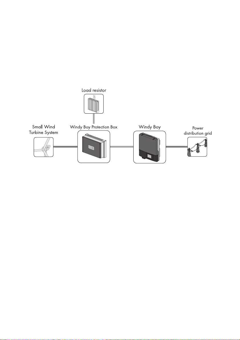
The Windy Boy is a transformerless wind energy inverter which converts the rectified alternating
current generated by the small wind turbine system, or other energy converters based on permanent
magnet generators, into grid-compatible alternating current, and feeds this into the electricity grid or
stand-alone grid.
Figure1: Structure of a small wind turbine system with Windy Boy
The Windy Boy is suitable for indoor and outdoor use.
Alternative uses of the Windy Boy not expressly recommended by SMA Solar Technology AG are
not permitted.
For safety reasons, it is not permitted to modify the product or install components that are not explicitly
recommended or distributed by SMA Solar Technology AG for this product.
The enclosed documentation is a part of this product.
• Read and adhere to the documentation.
• Keep the documentation in a convenient place for future reference.
User Manual WB3-5TL-21-BA-en-10 7
Page 8

2 Safety SMA Solar Technology AG
2.2 Safety Precautions
Electric Shock
High voltages are present in the live components of the inverter. Touching these components can
cause fatal electric shocks.
• Do not open the inverter.
• All work on the inverter (e.g. repairs, modifications) must be carried out by skilled persons only.
Burn Hazards
Some parts of the enclosure can become hot during operation.
• During operation, only touch the lower enclosure lid. Do not place any obj ect s on the enc losure ,
as this can lead to yield losses.
Inverter Damage
Overvoltages can destroy the inverter.
• If the display message DC overvoltage ‒ Disconnect generator is shown, inform your
installer IMMEDIATELY.
The inverter can be damaged by removing the ESS under load.
• Always leave the ESS plugged in during operation.
8 WB3-5TL-21-BA-en-10 User Manual
Page 9

SMA Solar Technology AG 3 Product Description
A
B
C
D
E
F
G
3 Product Description
3.1 Windy Boy
The Windy Boy is a transformerless wind energy inverter which converts the rectified alternating
current generated by the small wind turbine system into grid-compatible alternating current, and feeds
this into the electricity grid or stand-alone grid.
Figure2: Design of the Windy Boy
Position Description
A Cooling fins
BType label
CLEDs
DDisplay
E Electronic Solar Switch (ESS)*
FLower enclosure lid
G Upper enclosure lid
* Always leave the ESS plugged in during operation. The ESS must only be removed by a skilled person, in order to ensure
that no voltage is present in the inverter.
User Manual WB3-5TL-21-BA-en-10 9
Page 10

3 Product Description SMA Solar Technology AG
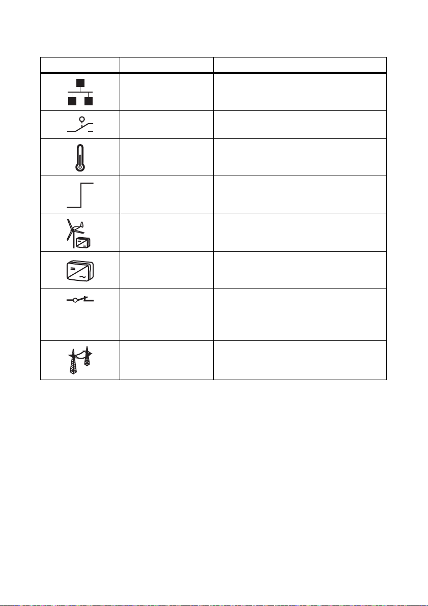
Symbols on the Inverter
Symbol Description Explanation
Inverter This symbol defines the function of the
green LED. The green LED indicates the
operating state of the inverter.
Observe the documentation This symbol defines the function of the
red LED. The red LED indicates an error.
• Contact installer.
Bluetooth This symbol defines the function of the
blue LED. The blue LED indicates that
communication via Bluetooth is
activated.
QR Code
®
Danger If a second protective conductor is
By scanning this code, the solar power
professional installing the inverter can
register the inverter and take part in the
SMA bonus programme.
required, the enclosure must be
additionally earthed.
10 WB3-5TL-21-BA-en-10 User Manual
Page 11

SMA Solar Technology AG 3 Product Description
3.2 Display
The display shows the current operating data of the inverter (e.g. current power, daily energy, total
energy) as well as events or errors. The power and energy are displayed as bars in the diagram.
The display values may deviate from the actual values and must not be used for billing purposes.
The values measured by the inverter are required for the operational control and to control the current
to be fed into the electricity grid.
Figure3: Design of the display (example)
Position Description Explanation
A Power Current power
B Day Daily energy
C Total Total amount of energy fed in until now
D Active functions The different symbols indicate which functions fo r
communication, grid management or
temperature derating are enabled or active.
E Line conductor Indicates which line conductor the displayed
values are assigned to
F Event number relating
to the electricity grid
GOutput voltage/
output current
H Event number relating
Event number of errors relating to the electricity
grid
Alternates between output voltage and output
current of a line conductor
Event number of errors relating to the inverter
to the inverter
User Manual WB3-5TL-21-BA-en-10 11
Page 12

3 Product Description SMA Solar Technology AG
Position Description Explanation
I Input voltage/input
current
K Event number relating
to the small wind
Alternates between input voltage and input
current of one input
Event number of errors relating to the small wind
turbine system
turbine system
L Text line Displays the event message or error message
M Power and yield curve Changes in power over the last 16 feed-in hours
or the energy yields over the last 16 days.
• In order to switch between the displays,
tap once on the enclosure lid.
Symbols on the Display
Symbol Description Explanation
Tapping You can operate the display by tapping on the
enclosure lid:
• T ap once : to a cti vate th e bac kli ght , to s cro ll
to the next text line, to switch between the
power graphs of the last 16 feed-in hours
and the energy yields of the last 16 days
• Tap twice in succession: the display
successively shows the firmware version,
the serial number or designation of the
inverter, Bluetooth NetID, the set country
data set and display language.
Telephone receiver Indicates that an error cannot be rectified on site
• Contact installer.
Spanner Indicates an error that can be rectified on site by
your installer.
• Contact installer.
Bluetooth Indicates that an active Bluetooth connection is
established
Bluetooth connection
quality
Indicates the quality of the Bluetooth connection
to other Bluetooth devices.
Speedwire If a Speedwire data module is installed in the
inverter, this symbol shows that there is a
connection to a network
12 WB3-5TL-21-BA-en-10 User Manual
Page 13
SMA Solar Technology AG 3 Product Description
Symbol Description Explanation
Webconnect function If a Webconnect data module is installed in the
inverter, this symbol shows that connection to
Sunny Portal is possible
Multi-function relay Indicates that the multi-function relay is active
Thermometer Indicates that the power of the inverter is limited
due to excessive temperature
Power limitation Indicates that the external active power limitation
via the plant control is active
Small wind turbine
‒
system with rectifier
Inverter ‒
Grid relay A closed grid relay indicates that the inverter is
feeding into the electricity grid.
An open grid relay shows that the inverter is
disconnected from the electricity grid.
Electricity grid ‒
User Manual WB3-5TL-21-BA-en-10 13
Page 14

3 Product Description SMA Solar Technology AG
3.3 Type Label
The type label uniquely identifies the inverter. The type label is located on the right-hand side of the
enclosure.
Figure4: Design of the type label
Position Description Explanation
A Model Inverter device type
B Date of manufacture Inverter manufacture date
(year-month-day)
C Additional information Field for additional information,
e.g. country-specific standard
information
D Device-specific characteristics ‒
E Serial No. Inverter serial number
You will require the information on the type label to use the inverter safely and when seeking customer
support from the SMA Service Line. The type label must be permanently attached to the inverter.
14 WB3-5TL-21-BA-en-10 User Manual
Page 15
SMA Solar Technology AG 3 Product Description
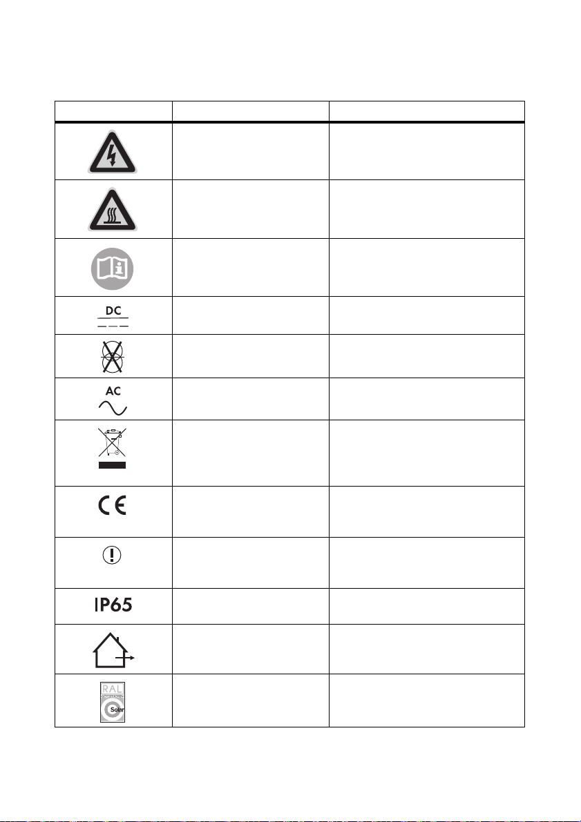
Symbols on the Type Label
Symbol Description Explanation
Danger to life due to high
voltages
Risk of burns from hot surfaces The product can become hot during
Observe the documentation Observe all documentation that is
DC Direct current
Without transformer The product does not have a
AC Alternating current
WEEE designation Do not dispose of the product together
CE marking The product complies with the
Device class ID The product is equipped with a wireless
Degree of protection The product is protected against dust
Outdoor The product is suitable for outdoor
The product operates at high voltages.
All work on the inverter must be carried
out by skilled persons only.
operation. Avoid contact during
operation.
supplied with the product.
transformer.
wi th h ouseh old waste but in acc ordan ce
with the locally applicable disposal
regulations for electronic waste.
requirements of the applicable
EC directives.
component and complies with device
class 2.
intrusion and water jets from any angle.
installation.
RAL quality mark for solar
products
The product complies with the
requirements of the German Institute for
Quality Assurance and Certification.
User Manual WB3-5TL-21-BA-en-10 15
Page 16

3 Product Description SMA Solar Technology AG
Symbol Description Explanation
Certified safety The product is VDE-tested and complies
with the requirements of the German
Equipment and Product Safety Act.
C-Tick The product complies with the
requirements of the applicable
Australian EMC standards.
3.4 Bluetooth
The inverter is equipped with a Bluetooth interface as standard and can communicate with special
SMA communication products or other inverters (for information on supported products, see
www.SMA-Solar.com).
If you wish to communicate via Bluetooth, you can protect the inverter with a plant password for the
user.
All inverters are delivered with a default plant password for the user (0000) as standard. To protect
the plant from unauthorised access, you must change the default plant password for the user using
Sunny Explorer (for information on changing the plant password, refer to the Sunny Explorer help).
3.5 Slot for Communication Interface
The inverter can optionally be fitted with an extra communication interface (e.g., RS485).
This communication interface enables the inverter to communicate with special SMA communication
products (for information on supported products, see www.SMA-Solar.com). The communication
interface can either be retrofitted or installed ex works according to a specific order.
16 WB3-5TL-21-BA-en-10 User Manual
Page 17

SMA Solar Technology AG 3 Product Description
3.6 Slot for Multi-Function Interface
The inverter is equipped with a slot for multi-function interfaces. This slot is designed to connect a
simple multi-function relay, an SMA Power Control Module or a fan retrofit kit. The multi-function
interface can either be retrofitted or installed ex works according to a specific order.
Multi-Function Relay
The multi-function relay can activate and deactivate error messages, for example.
SMA Power Control Module
The SMA Power Control Module enables the inverter to implement grid management and is also
equipped with a multi-function relay.
Fan Retrofit Kit
The fan retrofit kit provides additional cooling of the inverter in th e event of high a mbient tempera tures
and is likewise equipped with a multi-function relay. The fan retrofit kit and the SMA Power Control
Module cannot be operated in parallel.
User Manual WB3-5TL-21-BA-en-10 17
Page 18

4 LED Signals SMA Solar Technology AG
4 LED Signals
The LEDs indicate the operating state of the inverter.
Description Status Explanation
Green LED Glowing Operation
Flashing Requirements for connection to the electricity grid have
not been met.
Red LED Glowing Failure
• Contact installer.
Blue LED Glowing Bluetooth communication is activated.
18 WB3-5TL-21-BA-en-10 User Manual
Page 19

SMA Solar Technology AG 5 Cleaning the Inverter
5 Cleaning the Inverter
•
Damage to the display by use of cleaning agents
• If the inverter is dirty, clean the enclosure lid, the display and the LEDs using only clean
water and a cloth.
User Manual WB3-5TL-21-BA-en-10 19
Page 20

6 Glossary SMA Solar Technology AG
6 Glossary
Bluetooth
Bluetooth is a radio technology that allows the inverter and other communication products to
communicate with each other. For Bluetooth communication, the Bluetooth devices do not need to be
within sight of each other.
Energy
Energy is the power that a system can supply or consume within a certain time unit. Energy is
measured in Wh (watt hours). If, for instance, your inverter feeds in for half an hour at 3,000 W and
half an hour at 2,000 W, it will have fed a total of 2,500 Wh into the electricity grid.
Power
Power is the product of voltage and electrical current strength. Power is measured in W (watts).
The power shown in the display is an instantaneous value. It indicates the power that your inverter is
currently feeding into the electricity grid.
20 WB3-5TL-21-BA-en-10 User Manual
Page 21

SMA Solar Technology AG 7 Contact
7 Contact
If you have technical problems, first contact your installer. The following information is required in
order to provide you with the necessary assistance:
•Inverter device type
• Inverter serial number
• Firmware version of the inverter
• Special country-specific settings of the inverter (if applicable)
• Type and number of small wind turbine systems connected
• Installation location and installation altitude of the inverter
• Three-digit or four-digit event number and display message of the inverter
• Optional equipment, e.g. communication products
• Use of the multi-function relay (if available)
SMA Solar Technology AG
Sonnenallee 1
34266 Niestetal, Germany
www.SMA.de
SMA Service Line
Inverters +49 561 9522 1499
Communication: +49 561 9522 2499
Fax: +49 561 9522 4699
E‑Mail: ServiceLine@SMA.de
User Manual WB3-5TL-21-BA-en-10 21
Page 22

Page 23

SMA Solar Technology AG Legal Restrictions
Legal Restrictions
The information contained in this document is the property of SMA Solar Technology AG. Publishing its content, either partially or
in full, requires the written permission of SMA Solar Technology AG. Any internal company copying of the document for the
purposes of evaluating the product or its correct implementation is allowed and does not require permission.
SMA Factory Warranty
The current warranty conditions come enclosed with your device. These are also available online at www.SMA-Solar.com and can
be downloaded and are available on paper from the usual sales channels if required.
Trademarks
All trademarks are recognized even if these are not marked separately. Missing designations do not mean that a product or brand
is not a registered trademark.
The Bluetooth
Solar Technology AG is under licence.
QR Code
SMA Solar Technology AG
Sonnenallee 1
34266 Niestetal
Germany
Tel. +49 561 9522-0
Fax +49 561 9522-100
www.SMA.de
E-Mail: info@SMA.de
© 2004 to 2012 SMA Solar Technology AG. All rights reserved
®
wor d mark and logos are registere d trademarks own ed by Blu etooth SIG, Inc. and any use of suc h marks by SMA
®
is a registered trademark of DENSO WAVE INCORPORATED.
User Manual WB3-5TL-21-BA-en-10 23
Page 24

SMA Solar Technology
www.SMA-Solar.com
SMA Solar Technology AG
www.SMA.de
SMA Australia Pty. Ltd.
www.SMA-Australia.com.au
SMA Benelux bvba/sprl
www.SMA-Benelux.com
SMA Beijing Commercial Company Ltd.
www.SMA-China.com.cn
SMA Central & Eastern Europe s.r.o.
www.SMA-Czech.com
SMA France S.A.S.
www.SMA-France.com
SMA Hellas AE
www.SMA-Hellas.com
SMA Ibérica Tecnología Solar, S.L.U.
www.SMA-Iberica.com
SMA Solar India Pvt. Ltd.
www.SMA-India.com
SMA Italia S.r.l.
www.SMA-Italia.com
SMA Japan K.K.
www.SMA-Japan.com
SMA Technology Korea Co., Ltd.
www.SMA-Korea.com
SMA Middle East LLC
www.SMA-Me.com
SMA Portugal - Niestetal Services Unipessoal Lda
www.SMA-Portugal.com
SMA Solar (Thailand) Co., Ltd.
www.SMA-Thailand.com
SMA Solar UK Ltd.
www.SMA-UK.com
 Loading...