

Page 1
EN
Accessories for Central Inverter
VOLTAGE STABILIZER
Installation Guide
Ukonstanter-IEN103610 | 98-4042110 | Version 1.0
Page 2

Page 3

SMA Solar Technology AG Table of Contents
Table of Contents
1 Notes on this Manual. . . . . . . . . . . . . . . . . . . . . . . . . . . . . . 5
2 Safety . . . . . . . . . . . . . . . . . . . . . . . . . . . . . . . . . . . . . . . . . . 7
2.1 Appropriate Usage. . . . . . . . . . . . . . . . . . . . . . . . . . . . . . . . . . . 7
2.2 Safety Instructions . . . . . . . . . . . . . . . . . . . . . . . . . . . . . . . . . . . . 8
2.3 Personnel . . . . . . . . . . . . . . . . . . . . . . . . . . . . . . . . . . . . . . . . . . 9
3 Delivery. . . . . . . . . . . . . . . . . . . . . . . . . . . . . . . . . . . . . . . . 10
3.1 Check for Transport Damage . . . . . . . . . . . . . . . . . . . . . . . . . . 10
3.2 Scope of Supply . . . . . . . . . . . . . . . . . . . . . . . . . . . . . . . . . . . . 10
4 Mounting. . . . . . . . . . . . . . . . . . . . . . . . . . . . . . . . . . . . . . . 11
4.1 Choosing an Installation Site . . . . . . . . . . . . . . . . . . . . . . . . . . 11
4.2 Mounting the Voltage Stabilizer . . . . . . . . . . . . . . . . . . . . . . . . 12
5 Electrical Connection . . . . . . . . . . . . . . . . . . . . . . . . . . . . . 14
5.1 Overview of External Components for Internal Power Supply . 14
5.2 Line Circuit Breaker. . . . . . . . . . . . . . . . . . . . . . . . . . . . . . . . . . 14
5.3 Inserting the Cables . . . . . . . . . . . . . . . . . . . . . . . . . . . . . . . . . 15
5.4 Connecting the Cables Inside the Voltage Stabilizer . . . . . . . . 16
5.5 Connecting the Cables in the Sunny Central . . . . . . . . . . . . . . 20
6 Commissioning . . . . . . . . . . . . . . . . . . . . . . . . . . . . . . . . . . 23
7 Maintenance and Service . . . . . . . . . . . . . . . . . . . . . . . . . 24
8 Technical Data . . . . . . . . . . . . . . . . . . . . . . . . . . . . . . . . . . 25
9 Contact . . . . . . . . . . . . . . . . . . . . . . . . . . . . . . . . . . . . . . . . 26
Installation Guide Ukonstanter-IEN103610 3
Page 4

Table of Contents SMA Solar Technology AG
4 Ukonstanter-IEN103610 Installation Guide
Page 5

SMA Solar Technology AG 1Notes on this Manual
1 Notes on this Manual
Area of Validity
This manual is valid for the voltage stabilizer.
This manual supplements the installation manual of the following inverters:
• Sunny Central 400HE-11 (SC 400HE-11)
• Sunny Central 500HE-11 (SC 500HE-11)
• Sunny Central 630HE-11 (SC 630HE-11)
These inverter types will be referred to as "Sunny Central" in the following.
Combining the voltage stabilizer with other inverter types is not possible and is explicitly not
recommended.
Target Group
This guide is for electrically skilled persons. A qualified electrically skilled person is conversant with
the practices of installing electrical systems as well as the dangers and risks involved.
Additional Information
You can find further information on special subjects in the download area at www.SMA.de/en.
There are many items available for download including the following information:
•SunnyCentralxxxHE-11 installation manual
• technical information on the Sunny Central
Installation Guide Ukonstanter-IEN103610 5
Page 6
1Notes on this Manual SMA Solar Technology AG
%"/(&3
8"3/*/(
$"65*0/
/05*$&
Symbols Used
The following types of safety notes and general information are used in this manual:
"DANGER" indicates a hazardous situation which, if not avoided, will result in death or serious
injury.
"WARNING" indicates a hazardous situation which, if not avoided, could result in death or serious
injury.
"CAUTION" indicates a hazardous situation which, if not avoided, could result in minor or moderate
injury.
"NOTICE" indicates a situation that can result in property damage, if not avoided.
Information
Information provides tips that are valuable for the optimal installation and operation of your
product.
☑ This symbol indicates the result of an action.
✖ This symbol indicates a possible error.
6 Ukonstanter-IEN103610 Installation Guide
Page 7
SMA Solar Technology AG 2Safety
A
BC
S
M
A
SUNNY CENTRAL 630HE
2Safety
2.1 Appropriate Usage
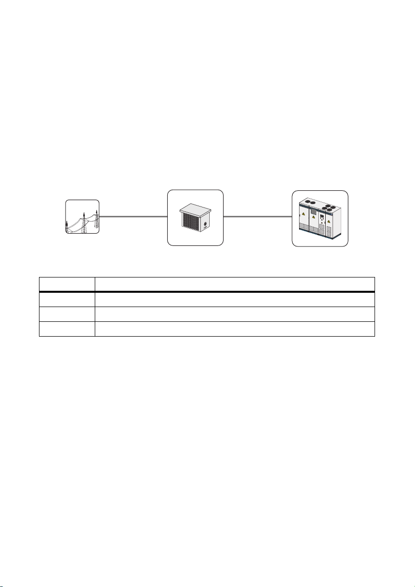
The voltage stabilizer connects the Sunny Central with the public power distribution grid in order to
secure the internal power supply of the inverter. The voltage stabilizer reduces fluctuating grid
voltages in order to ensure a constant power supply to the SunnyCentral.
The voltage stabilizer may only be used with a specially adapted Sunny Central xxxHE-11 device.
If a voltage stabilizer is installed later as an upgrade, SMA Solar Technology AG must be contacted
about the modification of the inverter.
Figure1:Principle of the voltage stabilizer
Position Description
A Power distribution grid
BVoltage stabilizer
C Sunny Central
Any other usage or installation of components and modifications than described in the usage
regulations jeopardize the operational safety of the device and void all warranty claims as well as
the operation permission.
Installation Guide Ukonstanter-IEN103610 7
Page 8

2Safety SMA Solar Technology AG
2.2 Safety Instructions
Following Handling Instructions
High voltages are present in the voltage stabilizer. Failure to follow this manual, the operating
instructions and the safety notes may lead to severe injury from electric shock. Only perform work as
described in this manual. Observe all safety notes.
Disconnecting the Device
Work on the inverter is only allowed if the power is disconnected and in compliance with the
guidelines that apply at the installation location.
• Disconnecting the device:
–grid voltage
• Ensure that the device cannot be reconnected.
• Ensure that no voltage is present in the system.
• Ground and short-circuit.
• Cover or safeguard any adjacent live components.
Error-Free Operation of the Voltage Stabilizer
In case of a ground fault, assume that grounded plant components are still live. Ensure there is no
voltage present before touching.
The operation of a damaged voltage stabilizer can lead to serious injuries through electric shock.
Operate the voltage stabilizer only if it is in a technically proper and operationally safe status.
Operate the voltage stabilizer only if there is no visible damage and check regularly for visible
damage. Ensure that all external safety equipment is freely accessible at all times and is checked for
proper functioning at least once a year.
Protective Conductor Connection
Also connect the grounding bridge when replacing the voltage stabilizer.
Warning Signs
Warning signs must be easily readable at all times and must be replaced in the event of
damage.
Storing the Documentation
Keep this documentation within close reach of the voltage stabilizer. It must be accessible to
service and maintenance personnel at all times.
8 Ukonstanter-IEN103610 Installation Guide
Page 9

SMA Solar Technology AG 2Safety
2.3 Personnel
All work on the voltage stabilizer may only be carried out by qualified technical personnel.
Qualified means that the personnel has the relevant training for the tasks.
The personnel must be familiar with the contents of this guide and the Sunny Central manual in order
to commission and operate the voltage stabilizer. Especially the safety notes must be observed.
Installation Guide Ukonstanter-IEN103610 9
Page 10

3Delivery SMA Solar Technology AG
3Delivery
3.1 Check for Transport Damage
Despite the robust packaging, damage can occur during shipping and transport. Check the voltage
stabilizer visually before installation. Should you detect any external defects, contact your supplier.
3.2 Scope of Supply
Figure2:Components of the supply
Position Description
AVoltage stabilizer
10 Ukonstanter-IEN103610 Installation Guide
Page 11

SMA Solar Technology AG 4Mounting
100 mm
100 mm
500 mm
500 mm
4Mounting
4.1 Choosing an Installation Site
Requirements:
☐ Installation site is located inside a closed building.
☐ The foundations must be level and solid.
☐ The installation site is not in close proximity to a source of heat.
☐ Minimum clearances have been observed.
Minimum Clearances:
Fi gur e3 :M ini mum cle ara nce s be twe en t he v olt age sta bil ize r an d non-electronic components in its close proximity.
Figure4:Minimum clearances between the voltage stabilizer and electronic components in its close proximity.
Installation Guide Ukonstanter-IEN103610 11
Page 12

4Mounting SMA Solar Technology AG
500 mm
SUNNY CENTRAL 630
SMA
Figure5:Minimum clearance to the Sunny Central
4.2 Mounting the Voltage Stabilizer
Additional Material:
☐ The screw anchors, screws and washers required for mounting must be provided by the
customer.
Figure6:Position of the mounting rail and measurements of the hole in the mounting rail
12 Ukonstanter-IEN103610 Installation Guide
Page 13

SMA Solar Technology AG 4Mounting
1. Mark the position of the drill holes.
2. Drill the holes and insert suitable screw anchors.
3. Attach the voltage stabilizer to the floor using appropriate screws and washers.
4. Check that the voltage stabilizer is securely in place.
Installation Guide Ukonstanter-IEN103610 13
Page 14

5Electrical Connection SMA Solar Technology AG
5 Electrical Connection
5.1 Overview of External Components for Internal Power Supply
Figure7:Connection area of the inverter and the voltage stabilizer
Position Description
AInverter
B Line circuit breaker (type D)
C Station sub-distribution
DVoltage stabilizer
E 415 V circuit (unstable input voltage)
F 230 V circuit (stabilized output voltage)
G Temperature monitoring
The temperature circuit monitors the operating temperature of the voltage stabilizer. If the operating
temperature of the voltage stabilizer exceeds 50 °C, the Sunny Central will shut down since the
voltage stabilizer will no longer be able to ensure a stable power supply.
5.2 Line Circuit Breaker
In order to operate the voltage stabilizer, it is necessary to secure the power supply of the
Sunny Central with a 16 A type D line circuit breaker. The line circuit breaker is located in the station
sub-distribution.
• Check which line circuit breaker is installed.
☑ A 16 A type D line circuit breaker is installed.
✖ There is no 16 A type D line circuit breaker installed?
14 Ukonstanter-IEN103610 Installation Guide
Page 15

SMA Solar Technology AG 5Electrical Connection
/05*$&
• Replace it with a matching type D line circuit breaker.
5.3 Inserting the Cables
Required cables:
☐2x1.5mm2 cable for temperature monitoring
☐3x4mm
☐2x4mm
☐1x4mm
Flashover along the surface of the cable insulation.
• Use separate cable channels for the 230 V circuit and the 415 V circuit in order to ensure
2
cable for the 230 V circuit, maximum cable length: 7 m
2
cable for the 415 V circuit
2
PE cable for the enclosure
sufficient insulation between the two circuits.
Figure8:Cable glands on the side
Position Description
A Cable gland for temperature monitoring
B Cable gland for 415 V circuit and the protective conductor cable
C Cable gland for the 230 V circuit
Installation Guide Ukonstanter-IEN103610 15
Page 16

5Electrical Connection SMA Solar Technology AG
/05*$&
1. Unscrew the screws on the cover and remove the
cover.
2. Insert the protective conductor cable through the cable gland.
3. Insert the temperature monitoring cables through the cable gland.
4. Insert the cable of the 415 V circuit through the cable gland.
5. Insert the cable of the 230 V circuit through the cable gland.
6. Attach the cable inside the voltage stabilizer in such a manner as to ensure proper strain relief.
5.4 Connecting the Cables Inside the Voltage Stabilizer
There will be no proper protection if the protective conductor cable is connected
incorrectly.
Check if the grounding bridge matches the circuit diagram.
Circuit Diagram
For all electrical connections, it is imperative that you use the provided Sunny Central circuit
diagram.
16 Ukonstanter-IEN103610 Installation Guide
Page 17

SMA Solar Technology AG 5Electrical Connection
Overview of the Connection Area in the Voltage Stabilizer
Figure9:
Object Description
A 415 V circuit
B 230 V circuit
C Temperature monitoring
Connection to Terminals
• All connection terminals that are not being used must be screwed tightly.
• Strip 5 mm from the cable insulation.
• Observe the following torques when connecting the cables to the terminals:
M3 0.6 … 0.8 Nm
M4 1.5 … 1.8 Nm
M6 3.2 … 3.7 Nm
Procedure:
• Connect the protective conductor cable.
• Connect the temperature monitoring.
• Connect the 230 V circuit.
• Connect the 415 V circuit.
• Close the voltage stabilizer.
Installation Guide Ukonstanter-IEN103610 17
Page 18

5Electrical Connection SMA Solar Technology AG
U
415
u
u
u
230
230
230
1
2
3
4
u
u
230
230
230
1
2
3
4
u
230
230
1
2
3
4
Connecting the Protective Conductor Cable
1. Check if the protective conductor bridge is
available at the terminal strip according to the
circuit diagram.
☑ Protective conductor bridge is available.
✖ Protective conductor bridge is not available?
• Establish protective conductor bridge
according to the circuit diagram.
2. Strip the cable insulation.
3. Attach a terminal lug to the cable.
4. Connect the protective conductor cable to the
protective conductor grounding point in the voltage
stabilizer.
5. Connect the protective conductor cable to the protective conductor rail in the station subdistribution outside of the voltage stabilizer.
Connecting the Temperature Monitoring
1. Strip the cable insulation.
2. Connect the cables to the terminals. Use wire
sleeves for this.
3. Tighten the cable screw connections.
18 Ukonstanter-IEN103610 Installation Guide
Page 19

SMA Solar Technology AG 5Electrical Connection
U
415
u
u
u
230
230
230
1
2
3
4
U
415
u
u
u
230
230
230
U
415
u
u
u
230
230
230
1
2
3
4
U
415
u
Connecting the 230 V Circuit
1. Strip the cable insulation.
2. Connect the cables to the terminals. Use wire
sleeves for this. Also connect the protective
conductor cable according to the circuit diagram.
3. Tighten the cable screw connections.
Connecting the 415 V Circuit
1. Strip the cable insulation.
2. Connect the cables to the terminals. Use wire
sleeves for this.
3. Tighten the cable screw connections.
Closing the Voltage Stabilizer
1. Put on the cover and tighten the screws.
Installation Guide Ukonstanter-IEN103610 19
Page 20

5Electrical Connection SMA Solar Technology AG
5
4
3
2
1
2
1
A
C
B
Z120-X120
Z121-X121
5.5 Connecting the Cables in the Sunny Central
Circuit Diagram
For all electrical connections, it is imperative that you use the provided Sunny Central circuit
diagram. The exact position of the terminal strip can be determined with the help of the
reference designation.
Overview of the Connection Area in the Sunny Central
Figure10:Connection terminal strip in the Sunny Central, examples shown here are for options 2/0 and 5/5
Object Description
A Temperature monitoring
B 230 V circuit
C 415 V circuit
Connection to Terminals
• All connection terminals that are not being used must be screwed tightly.
• Strip 5 mm from the cable insulation.
• Observe the following torques when connecting the cables to the terminals:
M3 0.6 … 0.8 Nm
M4 1.5 … 1.8 Nm
M6 3.2 … 3.7 Nm
20 Ukonstanter-IEN103610 Installation Guide
Page 21

SMA Solar Technology AG 5Electrical Connection
S
M
A
Procedure:
• Insert the cables into the inverter (see inverter documentation).
• Connect the temperature monitoring.
• Connect the 230 V circuit.
• Connect the 415 V circuit.
Connecting the Temperature Monitoring
1. Strip the cable insulation.
2. Insert a screwdriver into the square-shaped
opening next to the terminal and open the terminal
lock by pressing it.
3. Connect the cables to the terminals. Use wire
sleeves for this.
4. Pull the screwdriver out of the terminal.
5. Tighten the cable screw connections.
Installation Guide Ukonstanter-IEN103610 21
Page 22

5Electrical Connection SMA Solar Technology AG
S
M
A
S
M
A
Connecting the 230 V Circuit
1. Strip the cable insulation.
2. Insert a screwdriver into the square-shaped opening next the terminal and open the terminal lock
by pressing it.
3. Connect the cables to the terminals. Use wire
sleeves for this.
4. Pull the screwdriver out of the terminal.
5. Tighten the cable screw connections.
Connecting the 415 V Circuit
1. Strip the cable insulation.
2. Insert a screwdriver into the square-shaped opening next the terminal and open the terminal lock
by pressing it.
3. Connect the cables to the terminals. Use wire
sleeves for this.
4. Pull the screwdriver out of the terminal.
5. Tighten the cable screw connections.
22 Ukonstanter-IEN103610 Installation Guide
Page 23

SMA Solar Technology AG 6Commissioning
6Commissioning
Sunny Central Installation Manual
Follow all instructions in the Sunny Central installation manual.
Requirements for Commissioning
☐ There is a protective conductor connection between the voltage stabilizer and the
Sunny Central.
☐ All screws and cable glands are tight.
☐ The line circuit breaker is working properly.
The voltage stabilizer is started up as soon as the Sunny Central is started up.
Installation Guide Ukonstanter-IEN103610 23
Page 24

7Maintenance and Service SMA Solar Technology AG
7 Maintenance and Service
Maintenance Intervals
Observe the information in the Sunny Central maintenance guide. The maintenance guide
describes all relevant safety notes and maintenance intervals.
Maintenance Work:
• Press the test button on the residual current device in the Sunny Central every 2 years.
This ensures that the residual current device is working properly.
☑ The residual current device will trip and the indicator light on the service socket will go out.
✖ The residual current device does not trip or the indicator light on the service socket does not
go out?
• Replace the residual current device.
• Check that the connection cable is securely in place.
• Check the voltage stabilizer for dirt every 6 months.
• Always ensure that the vents are free of dirt or foreign objects.
• Check if the fan is functioning correctly every 12 months.
Service Work:
• Replace the capacitors after expiration of their service life. The service life of the capacitors is
limited to 100 000 hrs.
24 Ukonstanter-IEN103610 Installation Guide
Page 25

SMA Solar Technology AG 8Technical Data
8 Technical Data
Electrical Data
Maximum rated output power P
Nominal input voltage U
Input voltage range of the nominal input
nom
AC
U
AC
5kVA
415 V
−20%…+15%
voltage
Output voltage U
Output voltage range of the nominal
AC
U
AC
230 V
−10%…+10%
output voltage
Mechanical Data
Width x height x depth 740 mm x 620 mm x 550 mm
Weight 100 kg
Ambient Conditions
Permissible ambient temperature for installation
at altitudes of up to 1 000 m
Permissible ambient temperature for installation
at altitudes of up to 2 000 m
Maximum altitude above sea level 2 000 m
Degree of protection IP20
Insulation class ta55/F
−20°C…+50°C
−20°C…+40°C
Installation Guide Ukonstanter-IEN103610 25
Page 26

9Contact SMA Solar Technology AG
9Contact
If you have technical problems concerning our products, contact the SMA Serviceline. We need the
following information in order to provide you with the necessary assistance:
•inverter type
• serial number of inverter
• type and number of PV modules connected
• type of communication
• display information of the inverter
• error or warning number of the inverter
SMA Solar Technology AG
Sonnenallee 1
34266 Niestetal, Germany
www.SMA.de
SMA Serviceline
Tel. +49 561 9522 299
Fax +49 561 9522 3299
E‑Mail: SunnyCentral.Service@SMA.de
26 Ukonstanter-IEN103610 Installation Guide
Page 27

SMA Solar Technology AG Legal Restrictions
The information contained in this document is the property of SMA Solar Technology AG. Publishing its content, either partially or
in full, requires the written permission of SMA Solar Technology AG. Any internal company copying of the document for the
purposes of evaluating the product or its correct implementation is allowed and does not require permission.
Exclusion of liability
The general terms and conditions of delivery of SMA Solar Technology AG shall apply.
The content of these documents is continually checked and amended, where necessary. However, discrepancies cannot be
excluded. No guarantee is made for the completeness of these documents. The latest version is available online at www.SMA.de
or from the usual sales channels.
Guarantee or liability claims for damages of any kind are excluded if they are caused by one or more of the following:
• Damages during transportation
• Improper or inappropriate use of the product
• Operating the product in an unintended environment
• Operating the product whilst ignoring relevant, statutory safety regulations in the deployment location
• Ignoring safety warnings and instructions contained in all documents relevant to the product
• Operating the product under incorrect safety or protection conditions
• Altering the product or supplied software without authority
• The product malfunctions due to operating attached or neighboring devices beyond statutory limit values
• In case of unforeseen calamity or force majeure
The use of supplied software produced by SMA Solar Technology AG is subject to the following conditions:
• SMA Solar Technology AG rejects any liability for direct or indirect damages arising from the use of software developed by
SMA Solar Technology AG. This also applies to the provision or non-provision of support activities.
• Supplied software not developed by SMA Solar Technology AG is subject to the respective licensing and liability agreements
of the manufacturer.
SMA Factory Warranty
The current guarantee conditions come enclosed with your device. These are also available online at www.SMA.de and can be
downloaded or are available on paper from the usual sales channels if required.
Trademarks
All trademarks are recognized even if these are not marked separately. Missing designations do not mean that a product or brand
is not a registered trademark.
The Bluetooth
Solar Technology AG is under license.
SMA Solar Technology AG
Sonnenallee 1
34266 Niestetal
Germany
Tel. +49 561 9522-0
Fax +49 561 9522-100
www.SMA.de
E-Mail: info@SMA.de
© 2004 to 2010 SMA Solar Technology AG. All rights reserved
®
wor d mark an d logos are registe red trademar ks owned by Bluetoo th SIG, Inc . and any use o f such marks by SMA
Installation Guide Ukonstanter-IEN103610 27
Page 28

XXX4."4PMBSDPN
4."4PMBS5FDIOPMPHZ
4."4PMBS5FDIOPMPHZ"(
XXX4."EF
4.""NFSJDB--$
XXX4.""NFSJDBDPN
4."5FDIOPMPHZ"VTUSBMJB1UZ-UE
XXX4.""VTUSBMJBDPNBV
4."#FOFMVY413-
XXX4."#FOFMVYDPN
4."#FJKJOH$PNNFSDJBM$P-UE
XXX4."$IJOBDPN
4."$[FDI3FQVCMJDTSP
XXX4."$[FDIDPN
4."'SBODF4"4
XXX4."'SBODFDPN
4.")FMMBT"&
XXX4.")FMMBTDPN
4."*C©SJDB5FDOPMPHB4PMBS4-
XXX4."*CFSJDBDPN
4."*UBMJB4SM
XXX4."*UBMJBDPN
4."5FDIOPMPHZ,PSFB$P-UE
XXX4.",PSFBDPN
 Loading...