

Page 1
Installation Manual
SMA POWER CONTROL MODULE (PWCMOD)
PCONTROLMOD-IA-en-15 | Version 1.5 ENGLISH
Page 2

Legal Provisions SMA Solar Technology AG
Legal Provisions
The information contained in this document is the property of SMA Solar Technology AG. Publishing
its content, either partially or in full, requires the written permission of SMA Solar Technology AG.
Any internal company copying of the document for the purposes of evaluating the product or its
correct implementation is allowed and does not require permission.
SMA Warranty
You can download the current warranty conditions from the Internet at www.SMA-Solar.com.
Trademarks
All trademarks are recognized, even if not explicitly identified as such. A lack of identification does
not mean that a product or symbol is not trademarked.
The BLUETOOTH
and any use of these marks by SMA Solar Technology AG is under license.
Modbus® is a registered trademark of Schneider Electric and is licensed by the Modbus
Organization, Inc.
QR Code is a registered trademark of DENSO WAVE INCORPORATED.
®
Phillips
and Pozidriv® are registered trademarks of Phillips Screw Company.
®
Torx
is a registered trademark of Acument Global Technologies, Inc.
SMA Solar Technology AG
Sonnenallee 1
34266 Niestetal
Germany
Tel. +49 561 9522-0
Fax +49 561 9522-100
www.SMA.de
E-mail: info@SMA.de
© 2004 to 2014 SMA Solar Technology AG. All rights reserved.
®
word mark and logos are registered trademarks owned by Bluetooth SIG, Inc.
2 PCONTROLMOD-IA-en-15 Installation Manual
Page 3

SMA Solar Technology AG Table of Contents
Table of Contents
1 Information on this Document. . . . . . . . . . . . . . . . . . . . . . . . . . . 5
1.1 Validity. . . . . . . . . . . . . . . . . . . . . . . . . . . . . . . . . . . . . . . . . . . . . . . . . 5
1.2 Target Group. . . . . . . . . . . . . . . . . . . . . . . . . . . . . . . . . . . . . . . . . . . . 5
1.3 Further Information. . . . . . . . . . . . . . . . . . . . . . . . . . . . . . . . . . . . . . . . 5
1.4 Symbols. . . . . . . . . . . . . . . . . . . . . . . . . . . . . . . . . . . . . . . . . . . . . . . . 5
1.5 Typographies. . . . . . . . . . . . . . . . . . . . . . . . . . . . . . . . . . . . . . . . . . . . 6
1.6 Nomenclature . . . . . . . . . . . . . . . . . . . . . . . . . . . . . . . . . . . . . . . . . . . 6
1.7 Display of Parameters . . . . . . . . . . . . . . . . . . . . . . . . . . . . . . . . . . . . . 6
1.8 Figures. . . . . . . . . . . . . . . . . . . . . . . . . . . . . . . . . . . . . . . . . . . . . . . . . 6
2 Safety . . . . . . . . . . . . . . . . . . . . . . . . . . . . . . . . . . . . . . . . . . . . . . 7
2.1 Intended Use . . . . . . . . . . . . . . . . . . . . . . . . . . . . . . . . . . . . . . . . . . . . 7
2.2 Safety Information . . . . . . . . . . . . . . . . . . . . . . . . . . . . . . . . . . . . . . . . 7
2.3 Supported Products . . . . . . . . . . . . . . . . . . . . . . . . . . . . . . . . . . . . . . . 8
3 Scope of Delivery . . . . . . . . . . . . . . . . . . . . . . . . . . . . . . . . . . . . . 9
4 Product Description . . . . . . . . . . . . . . . . . . . . . . . . . . . . . . . . . . 10
4.1 SMA Power Control Module. . . . . . . . . . . . . . . . . . . . . . . . . . . . . . . 10
4.2 Type Label . . . . . . . . . . . . . . . . . . . . . . . . . . . . . . . . . . . . . . . . . . . . . 11
4.3 Multifunction Relay . . . . . . . . . . . . . . . . . . . . . . . . . . . . . . . . . . . . . . 11
5 Electrical Connection . . . . . . . . . . . . . . . . . . . . . . . . . . . . . . . . . 13
5.1 Mounting Position and Cable Route . . . . . . . . . . . . . . . . . . . . . . . . . 13
5.2 Cable Requirements. . . . . . . . . . . . . . . . . . . . . . . . . . . . . . . . . . . . . . 14
5.3 Installation of the Module . . . . . . . . . . . . . . . . . . . . . . . . . . . . . . . . . 15
5.3.1 Installing the Module in the Sunny Boy Smart Energy . . . . . . . . . . . 15
5.3.2 Installing the Module in the Sunny Tripower / Sunny Boy. . . . . . . . 17
5.4 Preparing the Enclosure Opening on the Inverter . . . . . . . . . . . . . . . 18
5.5 Preparing the Connection Cables for Connection to
Multi-Pole Plugs . . . . . . . . . . . . . . . . . . . . . . . . . . . . . . . . . . . . . . . . . 19
5.6 Connecting the Ripple Control Receiver . . . . . . . . . . . . . . . . . . . . . . 19
5.7 Using the Ripple Control Receiver Signal for Additional Inverters. . . 23
Installation Manual PCONTROLMOD-IA-en-15 3
Page 4

Table of Contents SMA Solar Technology AG
5.8 Multifunction Relay Connection. . . . . . . . . . . . . . . . . . . . . . . . . . . . . 24
5.8.1 Connection Options for the Multifunction Relay . . . . . . . . . . . . . . . 24
5.8.2 Connecting the Remote Terminal to the Multifunction Relay . . . . . . 28
6 Configuring the Module. . . . . . . . . . . . . . . . . . . . . . . . . . . . . . . 30
6.1 Information on Module Configuration. . . . . . . . . . . . . . . . . . . . . . . . 30
6.2 Setting the Operating Mode Active Power Limitation or Remote
Shutdown. . . . . . . . . . . . . . . . . . . . . . . . . . . . . . . . . . . . . . . . . . . . . . 30
6.3 Setting the Operating Mode of the Multifunction Relay . . . . . . . . . . 31
7 Troubleshooting . . . . . . . . . . . . . . . . . . . . . . . . . . . . . . . . . . . . . 32
8 Decommissioning . . . . . . . . . . . . . . . . . . . . . . . . . . . . . . . . . . . . 33
8.1 Removing the Module from the Sunny Boy Smart Energy. . . . . . . . . 33
8.2 Removing the Module from the Sunny Tripower / Sunny Boy. . . . . . 35
8.3 Disposing of the Module . . . . . . . . . . . . . . . . . . . . . . . . . . . . . . . . . . 35
9 Technical Data . . . . . . . . . . . . . . . . . . . . . . . . . . . . . . . . . . . . . . 36
10 Contact . . . . . . . . . . . . . . . . . . . . . . . . . . . . . . . . . . . . . . . . . . . . 37
4 PCONTROLMOD-IA-en-15 Installation Manual
Page 5
SMA Solar Technology AG 1 Information on this Document
1 Information on this Document
1.1 Validity
This d ocumen t is valid for de vice ty pe "PWCMOD-10" (SMA Power Control Module) from hardware
version A1.
1.2 Target Group
The tasks described in this document must be performed by qualified persons only. Qualified persons
must have the following skills:
• Training in the installation and commissioning of electrical devices and installations
• Knowledge of how to deal with the dangers and risks associated with installing and using
electrical devices and installations
• Knowledge of all applicable standards and directives
• Knowledge of how an inverter works and is operated
• Knowledge of and compliance with this document, including all safety information
1.3 Further Information
Links to additional information can be found at www.SMA-Solar.com:
Document title Document type
Firmware Update with SD Card Technical Description
Measured Values and Parameters Technical Description
1.4 Symbols
Symbol Explanation
Indicates a hazardous situation which, if not avoided, will result in death
or serious injury
Indicates a hazardous situation which, if not avoided, can result in death
or serious injury
Indicates a hazardous situation which, if not avoided, can result in minor
or moderate injury
Indicates a situation which, if not avoided, can result in property damage
Information that is important for a specific topic or goal, but is not
safety-relevant
☐ Indicates a requirement for meeting a specific goal
☑ Desired result
✖ A problem that might occur
Installation Manual PCONTROLMOD-IA-en-15 5
Page 6

1 Information on this Document SMA Solar Technology AG
1.5 Typographies
Typography Use Example
Bold • Display texts
• Elements on a user interface
• Connections
• Elements to be selected
• Elements to be entered
> • Connects several elements to
be selected
[Button/Key] • Button or key to be selected or
pressed
• The value can be found in the
field Energy.
• Select Settings.
• Enter the value 10 in the field
Minutes.
• Select Settings > Date.
• Select [Next].
1.6 Nomenclature
Complete designation Designation in this document
SMA Power Control Module Module
Sunny WebBox with
BLUETOOTH
PV system System
®
Wireless Technology
Sunny WebBox with BLUETOOTH
1.7 Display of Parameters
Depending on the type of communication (e.g. RS485, BLUETOOTH or Speedwire/Webconnect),
the parameters are displayed differently in the communication products. This document uses both
methods of displaying parameters.
Example: Display of the parameter for setting the operating mode of the multifunction
relay
• For communication via RS485: parameter Mlt.OpMode
• For communication via BLUETOOTH or Speedwire/Webconnect: parameter Operating
mode of multifunction relay
1.8 Figures
The figures in this document have been created for inverters of type Sunny Tripower and may deviate
slightly in some cases for inverters of type Sunny Boy.
6 PCONTROLMOD-IA-en-15 Installation Manual
Page 7
SMA Solar Technology AG 2 Safety
2 Safety
2.1 Intended Use
The SMA Power Control Module is a multifunction interface which enables grid management services
to be implemented for one inverter. In addition, the module is equipped with a multifunction relay.
The module is available as a retrofit kit or is pre-installed in the inverter.
The module must only be used with the supported products.
The inverter still complies with the standard after the product has been installed.
For safety reasons, it is not permitted to modify the product or install components that are not explicitly
recommended or distributed by SMA Solar Technology AG for this product.
The enclosed documentation is an integral part of this product.
• Read and observe the documentation.
• Keep the documentation in a convenient place for future reference.
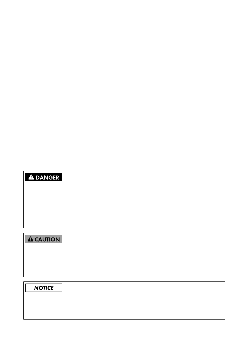
2.2 Safety Information
This section contains safety information that must be observed at all times when working on or with
the product. To prevent personal injury and property damage and to ensure long-term operation of
the product, read this section carefully and observe all safety information at all times.
Danger to life due to electric shock when opening the inverter
High voltages are present in the live components of the inverter. Touching live components results
in death or serious injury.
• Prior to performing any work on the inverter, always disconnect the inverter from voltage
sources on the AC and DC sides (see inverter manual). Observe the waiting time to allow the
capacitors to discharge.
Risk of burns due to hot enclosure parts
Some parts of the inverter enclosure can get hot during operation. Touching these enclosure parts
can result in burn injuries.
• During operation, do not touch any parts other than the lower enclosure lid of the inverter.
Damage to the inverter due to electrostatic discharge
The internal components of the inverter can be irreparably damaged by electrostatic discharge.
• Ground yourself before touching any inverter component.
Installation Manual PCONTROLMOD-IA-en-15 7
Page 8

2 Safety SMA Solar Technology AG
2.3 Supported Products
SMA Inverters
The module must only be installed in the following inverters from the indicated inverter firmware
version:
Sunny Boy From inverter firmware version
SB 2500TLST-21
SB 3000TLST-21
SB 3000TL-21
SB 3600TL-21
SB 4000TL-21
SB 5000TL-21
SB 6000TL-21
SB 3600SE-10
SB 5000SE-10
Sunny Tripower From inverter firmware version
STP 8000TL-10
STP10000TL-10
STP 12000TL-10
STP 15000TL-10
STP 17000TL-10
STP 20000TL-30
STP 25000TL-30
STP 15000TLHE-10
STP 20000TLHE-10
STP 15000TLEE-10
STP 20000TLEE-10
* If the firmware version of the inverter is lower than specified i n th e ta ble, you mus t up dat e th e in ver ter fir mwar e to the version
indicated or higher. For information on performing the firmware update, refer to the Technical Description "Firmware
Update with SD Card" at www.SMA-Solar.com.
2.55.23.R*
2.55.03.R*
2.4.30.R
2.50*
2.60.03.R*
2.51*
Additional SMA Products
The module can be configured with the following communication products:
• Sunny Explorer from software version 1.06*
• Sunny WebBox with BLUETOOTH from firmware version 1.03
• Sunny WebBox from firmware version 1.0
• SMA Cluster Controller from firmware version 1.0
* Inverters of type SB xx00SE-10 are supported from Sunny Explorer software version 1.07.03.
8 PCONTROLMOD-IA-en-15 Installation Manual
Page 9

SMA Solar Technology AG 3 Scope of Delivery
3 Scope of Delivery
Check the scope of delivery for completeness and any externally visible damage. Contact your
distributor if the delivery is incomplete or damaged.
Scope of delivery differs according to order option
If you have ordered the module separately from the inverter, the scope of delivery of the retrofit
kit includes the components shown below. If you have ordered the inverter together with the
module, the module will be pre-installed in the inverter upon delivery.
Figure1: Components included in the scope of delivery
Position Quantity Designation
A 1 SMA Power Control Module
B 2 Cable gland with single-hole seal
C2 Counter nut
D2 Two-hole seal
E 2 Three-pole plug
F 2 Six-pole plug
G 1 Installation manual
Installation Manual PCONTROLMOD-IA-en-15 9
Page 10
4 Product Description SMA Solar Technology AG
4 Product Description
4.1 SMA Power Control Module
The SMA Power Control Module is a multifunction interface which enables grid management services
to be implemented for one inverter. In addition, the module is equipped with a multifunction relay.
For the implementation of grid management services, the module rec eiv es the sp eci fic ati ons of t he g rid
operator via a ripple control receiver. In total, there are 16 setting possibilities or entry combinations.
The module can implement the following grid management services:
• Active power limitation in staged intervals of 0%, 30%, 60% and 100% of the agreed
connected active power
• For systems with a maximum power output of 6 kW and only in conjunction with inverters of
type SB xx00TL-21, SB xx00TLST-21, SB xx00SE-10:
– Remote shutdown within 50 ms
– Narrowing of the frequency limits to between 49.5 Hz and 50.5 Hz
The multifunction relay can be used for the following functions, for example:
• as fault indicator or operation signaling contact
• to control an external load or charge batteries
• to report the switching status of the grid relay (report start of grid feed-in to grid operator)
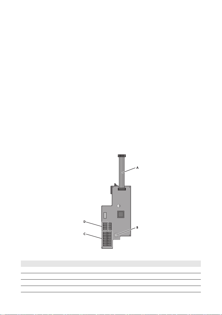
Figure2: Design of the SMA Power Control Module
Position Designation
ARibbon cable
B Screw for attaching the module in the inverter
C Terminals for ripple control receiver
D Multifunction relay terminal
10 PCONTROLMOD-IA-en-15 Installation Manual
Page 11

SMA Solar Technology AG 4 Product Description
4.2 Type Label
The type label clearly identifies the product. The type label is located on the back of the product.
You can read off the following data from the type label:
• Device type (Type)
•Serial number
• Hardware version (Version)
• Device-specific characteristics
Yo u wi ll r equ ire the inf ormatio n on the typ e la bel to u se t he p roduct safely and when seeking customer
support from the SMA Service Line. The type label must remain permanently attached to the product.
4.3 Multifunction Relay
Error message required by standard
In some countries, signaling of errors is required by standards, e.g. IEC 62109-2.
This requirement can be met in one of two ways:
• Operate the multifunction relay in the operating mode Fault indication (FltInd) and
connect a display to the multifunction relay that signals an error or the undisturbed
operation of the inverter.
• Activate the error alarm in Sunny Portal (see the Sunny Portal user manual at
www.SunnyPortal.com for information on receiving error alarms via Sunny Portal).
This requires the inverter to be registered on Sunny Portal.
You can use the multifunction relay for various purposes:
Operating mode of
multifunction relay
(Mlt.OpMod)
Fault indication (FltInd) The multifunction relay controls a display device which,
Self-consumption
(SelfCsmp)
Control via communication
(ComCtl)
Battery bank (BatCha) The multifunction relay controls the charging of external batteries
Installation Manual PCONTROLMOD-IA-en-15 11
Description
de pen din g on the t ype of c onn ect ion , signal s ei the r an err or o r th e
undisturbed operation of the inverter.
This operating mode is set by default.
The multifunction relay switches the loads on or off depending on
the amount of power available from the PV array. If a battery is
integrated in the system, the multifunction relay will still switch the
lo ads on o r of f de pen din g on t he a mou nt o f po wer avai lab le f rom
the PV array, not from the battery.
The multifunction relay switches loads on and off according to
commands transmitted by a communication product.
depending on the amount of power available from the system.
Page 12

4 Product Description SMA Solar Technology AG
Operating mode of
Description
multifunction relay
(Mlt.OpMod)
Fan control (FanCtl) The multifunction relay controls an external fan depending on the
temperature of the inverter.
If the temperature of the inverter is 5°C higher than a specific
threshold set in the inverter, the fan starts automatically. If the
temperature of the inverter is 10°C below the set threshold, the
fan stops automatically.
Switching status grid relay
(GriSwCpy)
The multifunction relay switches simultaneously with the grid relay
of the inverter and transmits a signal to the grid operator.
Depending on the intended application of the multifunction relay, the procedure for connection will
vary (see Section5.8.1 "Connection Options for the Multifunction Relay", page24).
After commissioning, you must set the operating mode of the multifunction relay via a communication
product and, if necessary, make further settings relating to the operating mode (see Section6.3
"Setting the Operating Mode of the Multifunction Relay", page31).
12 PCONTROLMOD-IA-en-15 Installation Manual
Page 13

SMA Solar Technology AG 5 Electrical Connection
5 Electrical Connection
5.1 Mounting Position and Cable Route
Mounting Position and Cable Route in the Sunny Boy Smart Energy
Fi gure 3: Mou nting posit ion an d cable r oute i n the S unny Boy S mart Energy with the enclosu re lid open a nd the
display flipped up
Position Designation
AInverter display (flipped up)
B Mounting position of the module
C Cable route to the module
D Cable gland M20 x 1.5
Installation Manual PCONTROLMOD-IA-en-15 13
Page 14

5 Electrical Connection SMA Solar Technology AG
Mounting Position and Cable Route in the Sunny Tripower / Sunny Boy
Figure4: Mounting position and cable route in the Sunny Tripower / Sunny Boy with the lower enclosure lid
open and the display flipped up
Position Designation
AInverter display (flipped up)
B Mounting position of the module
C Cable route to the module
D Cable gland M20 x 1.5
5.2 Cable Requirements
☐ UV-resistant for outdoor use
☐ Cable diameter when using a single-hole seal (one cable per cable gland): 5 mm to 13 mm
☐ Cable diameter when using a two-hole cable seal (two cables per cable gland): 6.0 mm
☐ Conductor cross-section: 0.5 mm
2
to 1.5 mm
☐ Maximum cable length: 100 m
☐ Required number of insulated conductors for connecting the ripple control receiver: at least five
☐ Required number of insulated conductors for connecting to the multifunction relay: at least two
Common connection cable
You can use one connection cable with at least seven insulated conductors to connect both the
ripple control receiver and the multifunction relay.
14 PCONTROLMOD-IA-en-15 Installation Manual
2
Page 15

SMA Solar Technology AG 5 Electrical Connection
5.3 Installation of the Module
5.3.1 Installing the Module in the Sunny Boy Smart Energy
Procedure:
1.
Danger to life due to electric shock when opening the inverter
High voltages are present in the live components of the inverter. Touching live components
results in death or serious injury.
• Disconnect the inverter from all voltage sources on the AC and DC sides and open it
(see inverter manual). Observe the waiting time to allow the capacitors to discharge.
2. Remove the display:
• Flip the display up.
• Remove the plug of the display ribbon cable
from the pin connector on the display
assembly.
• Flip the display down.
• Press the right-hand retainer outwards.
• Pull the display out of the right-hand retainer.
• Pull the display out of the left-hand retainer.
• Set the display aside in a safe place.
Installation Manual PCONTROLMOD-IA-en-15 15
Page 16

5 Electrical Connection SMA Solar Technology AG
3. Insert the ribbon cable of the module into the pin
connector on the display assembly.
4. Insert the module into the inverter. Insert the
left-hand key on the module into the hole in the
plastic retainer for the display assembly.
5. Use an Allen key (AF 3) to fasten the screw to the
module (torque: 1.5 Nm)
6. Install the display:
• (1) Plug the ribbon cable plug into the pin
connector on the display assembly.
• (2) Push the display into the right-hand retainer.
• (3) Push the display into the left-hand retainer.
16 PCONTROLMOD-IA-en-15 Installation Manual
Page 17

SMA Solar Technology AG 5 Electrical Connection
5.3.2 Installing the Module in the Sunny Tripower / Sunny Boy
Requirement:
☐ The firmware version of the inverter is supported (see Section2.3 "Supported Products",
page8). If necessary, update the inverter firmware (see the Technical Description "Firmware
Update with SD Card" at www.SMA-Solar.com).
Procedure:
1.
Danger to life due to electric shock when opening the inverter
High voltages are present in the live components of the inverter. Touching live components
results in death or serious injury.
• Disconnect the inverter from all voltage sources on the AC and DC sides and open it
(see the inverter manual). Observe the waiting time to allow the capacitors to discharge.
2. Loosen the screw of the display and flip the display up until it snaps into place.
3. If another communication interface is installed at the mounting location of the module,
disassemble it (see the installation manual of the communication interface).
4. Position the module in the inverter and lead the
ribbon cable upwards behind the display. The key
on the rear edge of the m odule m ust fit into the hole
in the plastic retainer in the inverter.
5. Use an Allen key (AF 3) to fasten the screw to the
module (torque: 1.5 Nm)
6. Flip the display down.
7. Insert the r ibb on c abl e in to th e le ft pi n co nne cto r on
the display of the inverter.
Installation Manual PCONTROLMOD-IA-en-15 17
Page 18

5 Electrical Connection SMA Solar Technology AG
5.4 Preparing the Enclosure Opening on the Inverter
Displayed graphics
Using example illustrations, this section shows only the preparation of the enclosure openings
on the inverter Sunny Tripower. However, the same method is used to connect to the module in
all inverters. Only the inverter environment is different.
Procedure:
1. Prepare the cable gland:
• If the enclosure opening of the inverter is sealed
with a filler plug, push the filler plug out of the
enclosure opening.
• If the enclosure opening of the inverter is sealed
with a cable gland installed in reversed
manner, loosen the external counter nut and
remove the cable gland.
2. Insert the cable gland from the outside and tighten
it with the counter nut from the inside.
3. If two cables must be led through the cable gland, press out the single-hole seal and replace
with a two-hole seal. Make sure that the enclosure opening of the inverter is tightly sealed.
18 PCONTROLMOD-IA-en-15 Installation Manual
Page 19

SMA Solar Technology AG
5.5 Preparing the Connection Cables for Connection to Multi-Pole Plugs
Always proceed as follows to prepare connection cables for connection to multi-pole plugs.
Procedure:
1. Trim 4 cm of the cable sheath at the end of the connection cable to be attached to the multi-pole
plug.
2. Trim unused insulated conductors flush with the cable sheath.
3. Strip off the conductor insulation by 6 mm.
5.6 Connecting the Ripple Control Receiver
Additionally required material (not included in the scope of delivery):
☐ One ripple control receiver with four outputs (see figure 5)
☐ One or two connection cables (see Section5.2 "Cable Requirements", page14)
Requirements:
☐ The connection cable must have been prepared for connection to the multi-pole plug (see
Section5.5 "Preparing the Connection Cables for Connection to Multi-Pole Plugs", page19).
☐ The enclosure opening on the inverter must be prepared (see Section5.4 "Preparing the
Enclosure Opening on the Inverter", page18).
Duplicate terminals for ripple control receiver
The ripple control receiver can be connected either to pins 1 to 5 or to pins 14 to 18.
The pins 1/18, 2/17, 3/16, 4/15 and 5/14 are each bridged so that a loop through of the
ripple control receiver signals is possible.
Figure5: Pin assignment of the module at the ripple control receiver terminals
Installation Manual PCONTROLMOD-IA-en-15 19
Page 20

5 Electrical Connection SMA Solar Technology AG
Pin Signal
Pin 5 / Pin 14 + 12 V
Pin 4 / Pin 15 D4
Pin 3 / Pin 16 D3
Pin 2 / Pin 17 D2
Pin 1 / Pin 18 D1
Functions of Signals D1 to D4 in Operating Mode Remote Shutdown
(Default Settings for Italy)
D1 D2 D3*
D4* Function
Closed Closed Open/Closed Open/Closed No specification
Open Closed Open/Closed Open/Closed Remote shutdown
Closed Open Open/Closed Open/Closed Narrowing of
frequency limits
Open Open Open/Closed Open/Closed Remote shutdown
* The signals D3 and D4 are not evaluated in the operating mode Remote shutdown.
20 PCONTROLMOD-IA-en-15 Installation Manual
Page 21

SMA Solar Technology AG 5 Electrical Connection
Value
-1%***
communication product
D1: 0| D2: 0| D3: 0| D4: 1 100%
Open Closed Open Open D1: 0| D2: 1| D3: 0| D4: 0 30%
Open Open Open Open D1: 0| D2: 0| D3: 0| D4: 0**
Closed Open Open Open D1: 1| D2: 0| D3: 0| D4: 0 0%
Digital input D1 Digital input D2 Digital input D3 Digital input D4 Display in the
Functions of Signals D1 to D4 in Operating Mode Active Power Limitation (Default Settings for Germany)
Installation Manual PCONTROLMOD-IA-en-15 21
Open Open Closed Open D1: 0| D2: 0| D3: 1| D4: 0 60%
Closed Closed Open Open D1: 1| D2: 1| D3: 0| D4: 0 -1%***
Open Closed Closed Open D1: 0| D2: 1| D3: 1| D4: 0 -1%***
Closed Open Closed Open D1: 1| D2: 0| D3: 1| D4: 0 -1%***
Open Open Open Open/Closed*
Closed Closed Closed Open D1: 1| D2: 1| D3: 1| D4: 0 -1%***
Closed Open Open Closed D1: 1| D2: 0| D3: 0| D4: 1 -1%***
Open Closed Open Closed D1: 0| D2: 1| D3: 0| D4: 1 -1%***
Closed Closed Open Closed D1: 1| D2: 1| D3: 0| D4: 1 -1%***
Open Open Closed Closed D1: 0| D2: 0| D3: 1| D4: 1 -1%***
Closed Open Closed Closed D1: 1| D2: 0| D3: 1| D4: 1 -1%***
Open Closed Closed Closed D1: 0| D2: 1| D3: 1| D4: 1 -1%***
Closed Closed Closed Closed D1: 1| D2: 1| D3: 1| D4: 1 -1%***
* Depending on the number of inputs of the ripple control receiver to be connected
Instantaneous value.
** When using the Sunny WebBox with RS485 communication, observe the following: If there is no signal, the value D0 is displayed for the parameter PCM-DigInStt under
*** The value "-1%" blocks the entry combination.
Page 22

5 Electrical Connection SMA Solar Technology AG
Procedure:
1.
Danger to life due to electric shock from faulty connection of the ripple control
receiver
In the event of faulty connection of the connection cable to the ripple control receiver, grid
voltage may be present in the module.
• Do not connect the insulated conductors of the connection cable to the line conductors of
the ripple control receiver.
• When connecting, ensure that no bridge is being used in the ripple control receiver.
2. Connect the connection cable to the ripple control receiver (see ripple control receiver manual).
Trim the unused insulated conductors up to the cable sheath and note the conductor colors.
Ripple control receiver
signal
Insulated conductor color Module
pin assignment
+ 12 V Pin 5 / Pin 14
D4 Pin 4 / Pin 15
D3 Pin 3 / Pin 16
D2 Pin 2 / Pin 17
D1 Pin 1 / Pin 18
3. Insert the connection cable through the seal and cable gland into the inverter.
4. Connect the connection cable to the six-pole plug as follows:
• Release the required conductor inlets of the plug using a screwdriver.
• Insert the insulated conductors into the conductor inlets. Make sure that the noted conductor
colors correspond to the pin assignment of the module.
5. Insert the six-pole plug into the terminal of the module. Observe the pin assignment.
6. Fasten the swivel nut hand-tight to the cable gland.
Ensure that the cable is securely in place and that
the enclosure opening of the inverter is tightly
sealed.
7. Flip down the display and fasten the screw hand-tight.
8. Close and commission the inverter (see inverter manual).
22 PCONTROLMOD-IA-en-15 Installation Manual
Page 23

SMA Solar Technology AG 5 Electrical Connection
5.7 Using the Ripple Control Receiver Signal for Additional Inverters
Additionally required material (not included in the scope of delivery):
☐ One connection cable for each additional inverter (see Section5.2 "Cable Requirements",
page14)
Requirements:
☐ The module must be installed in all inverters (see Section5.3 "Installation of the Module",
page15).
☐ The ripple control receiver must be connected to one of the modules (see Section5.6
"Connecting the Ripple Control Receiver", page19).
☐ The required enclosure openings on all inverters must be prepared (see Section5.4 "Preparing
the Enclosure Opening on the Inverter", page18).
☐ Both ends of the connection cable must be prepared for connection to a multi-pole plug
(see Section5.5 "Preparing the Connection Cables for Connection to Multi-Pole Plugs",
page19).
Possible to connect a maximum of five modules in parallel
You can use the signal from one ripple control receiver for a maximum of five inverters with
modules.
Figure6: Cabling for transmission of the signal from the ripple control receiver (example)
Installation Manual PCONTROLMOD-IA-en-15 23
Page 24

5 Electrical Connection SMA Solar Technology AG
Procedure:
1. Insert one end of the cable in inverter 1 and the other end in inverter 2. Each cable must be
routed through the seal and the cable gland of the inverter.
2. Connect a six-pole plug to each end of the cable as follows:
• Release the required conductor inlets of the plug using a screwdriver.
• Insert the insulated conductors into the conductor inlets. Make sure that the noted conductor
colors correspond to the pin assignment of the module.
3. In inverter 1, connect the six-pole plug to the free terminal for the ripple control receiver.
Observe the pin assignment.
4. In inverter 2, connect the six-pole plug to one of the terminals for the ripple control receiver.
Observe the pin assignment.
5. Fasten the swivel nut of the cable gland on both inverters hand-tight. Ensure that the cable is
securely in place and that the enclosure opening of the inverter is tightly sealed.
6. On both inverters, flip down the display and fasten the display screw hand-tight.
7. Close and commission both inverters (see inverter manual).
5.8 Multifunction Relay Connection
5.8.1 Connection Options for the Multifunction Relay
Depending on the required purpose of the multifunction relay, you can choose between the following
connection options (see Section4.3 "Multifunction Relay", page11):
Operating mode of
multifunction relay
(Mlt.OpMod)
Fault indication (FltInd) Using the multifunction relay as fault indicator contact
Self-consumption
(SelfCsmp)
Control via communication
(ComCtl)
Battery bank (BatCha) Controlling loads or charging batteries in a power-dependent
Fan control (FanCtl) Connecting the external fan (see fan documentation)
Switching status grid relay
(GriSwCpy)
24 PCONTROLMOD-IA-en-15 Installation Manual
Connection option
Controlling loads or charging batteries in a power-dependent
way via the multifunction relay
Controlling loads or charging batteries in a power-dependent
way via the multifunction relay
way via the multifunction relay
Reporting the switching status of the grid relay
Page 25

SMA Solar Technology AG 5 Electrical Connection
Using the Multifunction Relay as a Fault Indicator Contact or Operation Signaling
Contact
You can use the multifunction relay as a fault indicator contact for displaying or reporting inverter
errors. This requires a parallel connection. Alternatively, you can choose to have the undisturbed
operation displayed or reported. This requires a series connection. You can connect several inverters
to one fau lt in dic ato r co nta ct or ope rat ion sign ali ng c ont act . Yo u must connect the mu ltifunctio n rela ys
of several inverters in parallel.
Figure7: Wiring diagram with several inverters for connection of an operation signaling contact and wiring
Installation Manual PCONTROLMOD-IA-en-15 25
diagram for connection of a fault indicator contact (example)
Page 26

5 Electrical Connection SMA Solar Technology AG
Controlling loads or charging external batteries in a power-dependent way via
the multifunction relay
Loads can be controlled and external batteries charged in a power-dependent way via the
multifunction relay. To enable this function, a contactor (K1) must be connected to the multifunction
relay. The contactor (K1) switches the operating current for the load on or off. If you want external
batteries to be charged depending on the available power, the contactor serves to activate or
deactivate the charging of the batteries.
Figure8: Wiring diagram for connection to control a load or for the power-dependent charging of the batteries
26 PCONTROLMOD-IA-en-15 Installation Manual
Page 27

SMA Solar Technology AG 5 Electrical Connection
Reporting the Switching Status of the Grid Relay
The multifunction relay can trip a signal to the grid operator as soon as the first inverter connects to
the utility grid. To enable this function, you must switch the multifunction relays of all connected
inverters in parallel.
Figure9: Wiring diagram for reporting the switching status of the grid relay (example)
Installation Manual PCONTROLMOD-IA-en-15 27
Page 28

5 Electrical Connection SMA Solar Technology AG
5.8.2 Connecting the Remote Terminal to the Multifunction Relay
Requirements:
☐ You must select the connection option depending on the desired function of the multifunction
relay (see Section5.8.1 "Connection Options for the Multifunction Relay", page24).
☐ The technical requirements of the multifunction relay must be met (see Section9 "Technical
Data", page36).
☐ The enclosure opening on the inverter must be prepared (see Section5.4, page18).
☐ The connection cable must have been prepared for connection to the multi-pole plug
(see Section5.5, page19).
☐ Only use contactors which meet the connection requirements of the multifunction relay
(see Section9 "Technical Data", page36).
Destruction of the multifunction relay as a result of excessive contact load
• Observe the maximum switching voltage and maximum switching current (see Section9
"Technical Data", page36).
•Only use suitable contactors (see Section9 "Technical Data", page36).
Figure10: Pin assignment of the module at the multifunction relay terminal
Pin Signal Explanation
9NCBack contact
8NOFront contact
7 CO Change-over contact
28 PCONTROLMOD-IA-en-15 Installation Manual
Page 29

SMA Solar Technology AG 5 Electrical Connection
Procedure:
1. Connect the connection cable to the remote terminal (see the remote terminal manual). Trim the
unused insulated conductors up to the cable sheath and note down the conductor colors.
2. Insert the connection cable through the seal and cable gland into the inverter.
3. Connect the connection cable to the three-pole plug as follows:
• Release the required conductor inlets of the plug using a screwdriver.
• Insert the insulated conductors into the conductor inlets. Make sure that the noted conductor
colors correspond to the pin assignment of the module.
4. Connect the three-pole plug to the multifunction relay terminal of the module. Observe the pin
assignment.
5. Fasten the swivel nut hand-tight to the cable gland.
Ensure that the cable is securely in place and that
the enclosure opening of the inverter is tightly
sealed.
6. Flip down the display and fasten the screw hand-tight.
7. Close and commission the inverter (see inverter manual).
8. Use a communication product to set the operating mode of the multifunction relay (see
communication product manual).
9. If available, switch on the external supply voltage of the multifunction relay.
Installation Manual PCONTROLMOD-IA-en-15 29
Page 30

6 Configuring the Module SMA Solar Technology AG
6 Configuring the Module
6.1 Information on Module Configuration
Active power reduction to one of the 16 values set is realized within five seconds in the inverter.
Grid disconnection is possible within two seconds. In order to block an entry combination, the value
−1% mu st b e se t in the c omm uni cat ion pro duc t (s ee ta ble on p age 21) . Thi s en abl es u nas sig ned ent ry
combinations to be blocked.
If the grid operator does not permit the inverter to still feed in a low amount of active power when
limited to 0%, you must set the following parameter for grid disconnection. Setting this parameter
additionally opens the grid relays at a command of 0%. As a result, the inverter disconnects from the
utility grid and grid feed-in is no longer possible. Depending on the type of communication and the
communication product used, the parameter name may vary:
Type of
communication
BLUETOOTH,
Speedwire/
Webconnect
RS485 P-GriSwOpnZerW Yes/No
When the parameter is activated (Yes), the inverter disconnects from the utility grid when the signal
"0%" is issued. When the parameter is deactivated (No), the inverter continues to feed in with
minimum power when the signal "0%" is issued.
You can set the operating mode of the multifunction relay by means of a communication product
(for a detailed description of the operating parameters, see the Technical Description "Measured
Values and Parameters" at www.SMA-Solar.com).
Parameter name Setting
Equipment & device control system > Configuration
of feed-in management > Grid disconnection at 0%
or 0W setpoint, configuration of feed-in
management
Yes/No
6.2 Setting the Operating Mode Active Power Limitation or Remote Shutdown
Depending on the o rdered cou ntry op tion, the o perati ng mode Active power limitation or Remote
shutdown is activated by default.
Procedure:
• If you wish to use the operating mode Active power limitation, select the parameter
Operating mode of Power Control Module/PCM-OpMode and set it to the value Active
power limitation/ModWMax.
• If you wish to use the operating mode Remote shutdown, select the parameter Operating
mode of Power Control Module/PCM-OpMode and set it to the value Remote
shutdown/ModRemOff.
30 PCONTROLMOD-IA-en-15 Installation Manual
Page 31

SMA Solar Technology AG 6 Configuring the Module
6.3 Setting the Operating Mode of the Multifunction Relay
Procedure:
• Set the operating mode of the multifunction relay.
• If one of the following operating modes is used, you will need to carry out further settings for
the operating mode:
– Self-consumption/SelfCsmp
– Control via communication/ComCtl
– Battery bank/BatCha
Setting the Operating Mode of the Multifunction Relay
By default, the multifunction relay is set to activate a fault indicator if an error occurs. If you wish to
use the multifunction relay for another purpose, you will need to set the operating mode.
• Select the parameter Operating mode of multifunction relay/Mlt.OpMode and set the
desired operating mode (see Section4.3 "Multifunction Relay", page11).
Settings for Operating Mode Self-Consumption/SelfCsmp
• S et t he p owe r th res hol d fr om w hic h a l oad is t o be swi tch ed o n. S ele ct t he p ara met er Minimum
On time for MFR self-consumption/Mlt.MinOnPwr and set the desired power.
• Set the minimum time for which the power must exceed the set threshold in order to switch on
the load. Select the parameter Minimum On power for MFR self-consumption/
Mlt.MinOnPwr and set the desired minimum time.
• Set the minimum duration for which the load remains switched on. Select the parameter
Minimum On time for MFR self-consumption/Mlt.MinOnTmm and set the minimum
duration.
Settings for Operating Mode Control via Communication/ComCtl
• Set the status of the multifunction relay where it is to be controlled via a communication product.
Select the parameter Status of MFR with control via communication/MltComCtl.Sw and
set the status.
Settings for Operating Mode Battery bank/BatCha
• Set the power threshold from which the battery is to be charged. Select the parameter
Minimum on-power of MFR battery bank/Mlt.BatCha.Pwr and set the desired power.
• Set the minimum time which must elapse after charging the battery before it can be charged
again. Select the parameter Minimum On power for MFR battery bank/
Mlt.BatCha.Tmm and set the minimum time.
Installation Manual PCONTROLMOD-IA-en-15 31
Page 32

7 Troubleshooting SMA Solar Technology AG
7 Troubleshooting
Problem Cause and corrective measures
The inverter with module is not displayed in
Sunny Explorer.
The inverter with module has not been
commissioned.
Corrective measure:
• Commission the inverter with module
(see inverter manual).
The module is not properly connected.
Corrective measure:
•Ensure that the module is correctly
connected (see Section5 "Electrical
Connection", page13).
The firmware version of the inverter is not
supported (see Section2.3 "Supported
Products", page8).
Corrective measure:
• Update the inverter firmware (see inverter
manual).
The software version of Sunny Explorer is older
than version 1.06.
Corrective measure:
• Download Sunny Explorer from software
version 1.06 at www.SMA-Solar.com.
32 PCONTROLMOD-IA-en-15 Installation Manual
Page 33

SMA Solar Technology AG 8 Decommissioning
8 Decommissioning
8.1 Removing the Module from the Sunny Boy Smart Energy
Procedure:
1.
Danger to life due to electric shock when opening the inverter
High voltages are present in the live components of the inverter. Touching live components
results in death or serious injury.
• Disconnect the inverter from all voltage sources on the AC and DC sides and open it
(see inverter manual). Observe the waiting time to allow the capacitors to discharge.
2. Remove the display:
• Flip the display up.
• Remove the plug of the display ribbon cable
from the pin connector on the display
assembly.
• Flip the display down.
• (1) Press the right-hand retainer outwards.
• (2) Pull the display out of the right-hand
retainer.
• (3) Pull the display out of the left-hand retainer.
• Set the display aside in a safe place.
Installation Manual PCONTROLMOD-IA-en-15 33
Page 34

8 Decommissioning SMA Solar Technology AG
3. Remove the plug of the module ribbon cable from
the pin connector on the display assembly.
4. Loosen the screw on the module and remove the module from the inverter.
5. Install the display:
• (1) Plug the ribbon cable plug into the pin
connector on the display assembly.
• (2) Push the display into the right-hand retainer.
• (3)Push the display into the left-hand retainer.
6. Close the inverter (see inverter manual).
34 PCONTROLMOD-IA-en-15 Installation Manual
Page 35

SMA Solar Technology AG 8 Decommissioning
8.2 Removing the Module from the Sunny Tripower / Sunny Boy
Procedure:
1.
Danger to life due to electric shock when opening the inverter
High voltages are present in the live components of the inverter. Touching live components
results in death or serious injury.
• Disconnect the inverter from all voltage sources on the AC and DC sides and open it
(see inverter manual). Observe the waiting time to allow the capacitors to discharge.
2. Press the left-hand and right-hand lock hooks
outwards and remove the ribbon cable plug from
the left-hand pin connector on the inverter display.
3. Loosen the display screw and flip the display up.
4. Remove the plug for the ripple control receiver and/or multifunction relay from the module.
5. Open the cable gland(s) and remove the connection cables for the ripple control receiver and/
or multifunction relay from the inverter.
6. Seal the enclosure opening of the inverter using a filler plug. Make sure that the enclosure
opening of the inverter is tightly sealed.
7. Remove the module from the interface slot.
8. Flip down the display and fasten the screw hand-tight.
9. Close the inverter (see inverter manual).
8.3 Disposing of the Module
• Dispose of the module in accordance with the disposal regulations for electronic waste
applicable at the installation site.
Installation Manual PCONTROLMOD-IA-en-15 35
Page 36

9 Technical Data SMA Solar Technology AG
9 Technical Data
Connections
Ripple control receiver 4 digital inputs
Multifunction relay Relay output
Voltage Supply
Voltage supply via inverter
Ambient Conditions during Operation
Ambient temperature − 25°C to +85°C
Relative humidity, non-condensing 4% to 100%
Maximum height above mean sea level 3,000 m
Ambient Conditions for Storage/Transport
Ambient temperature − 40°C to +70°C
Relative humidity, non-condensing 10% to 95%
Maximum height above mean sea level 3,000 m
General Data
Dimensions (width x height x depth) 58 mm x 115 mm x 31 mm
Weight 49 g
Mounting location in the inverter
Degree of protection*
Required degree of protection of the inverter IP54
Maximum number of modules switched in
parallel
* in accordance with IEC 60529
IP20
5
Multifunction Relay
Maximum DC switching voltage 30 V
Maximum DC switching current 1.0 A
Terminal Three-pole plug
Minimum electrical endurance when the
100,000 switching cycles
maximum switching voltage and maximum
switching current are complied with
36 PCONTROLMOD-IA-en-15 Installation Manual
Page 37

SMA Solar Technology AG 10 Contact
10 Contact
If you have technical problems concerning our products, please contact the SMA Service Line.
We require the following information in order to provide you with the necessary assistance:
•Inverter
– Serial number
– Firmware version (tap the inverter display twice or see Sunny Portal or Sunny Explorer)
– Special country-specific settings (if applicable)
•Module
– Serial number
– Hardware version
– Application of the multifunction relay
• Communication product (e.g. Sunny Explorer)
–Type
– Serial number or software version
• Detailed description of the problem
Australia SMA Australia Pty Ltd.
Sydney
Belgien/
Belgique/
België
Brasil Vide España (Espanha)
Česko SMA Central & Eastern Europe
Chile Ver España
Danmark Se Deutschland (Tyskland)
Installation Manual PCONTROLMOD-IA-en-15 37
SMA Benelux BVBA/SPRL
Mechelen
s.r.o.
Praha
Toll free for
Australia:
International: +61 2 9491 4200
+32 15 286 730
+420 235 010 417
1800 SMA AUS
(1800 762 287)
Page 38

10 Contact SMA Solar Technology AG
Deutschland SMA Solar Technology AG
Niestetal
España SMA Ibérica Tecnología Solar,
S.L.U.
Barcelona
France SMA France S.A.S.
Lyon
India SMA Solar India Pvt. Ltd.
Mumbai
Italia SMA Italia S.r.l.
Milano
Κύπρος/
Kıbrıs
Luxemburg/
Luxembourg
Βλέπε Ελλάδα/
Bkz. Ελλάδα (Yunanistan)
Siehe Belgien
Voir Belgique
Magyarország lásd Česko (Csehország)
Nederland zie Belgien (België)
Österreich Siehe Deutschland
Perú Ver España
Polska Patrz Česko (Czechy)
Medium Power Solutions
Wechselrichter:
Kommunikation:
+49 561 9522-1499
+49 561 9522-2499
SMA Online Service Center:
www.SMA.de/Service
Hybrid Energy Solutions
Sunny Island: +49 561 9522-399
PV-Diesel
+49 561 9522-3199
Hybridsysteme:
Power Plant Solutions
Sunny Central: +49 561 9522-299
Llamada gratuita en
900 14 22 22
España:
Internacional: +34 902 14 24 24
Medium Power Solutions
Onduleurs :
Communication :
+33 472 09 04 40
+33 472 09 04 41
Hybrid Energy Solutions
Sunny Island : +33 472 09 04 42
Power Plant Solutions
Sunny Central : +33 472 09 04 43
+91 22 61713888
+39 02 8934-7299
38 PCONTROLMOD-IA-en-15 Installation Manual
Page 39

SMA Solar Technology AG 10 Contact
Portugal SMA Solar Technology Portugal,
Unipessoal Lda
Lisboa
România Vezi Česko (Cehia)
Schweiz Siehe Deutschland
Slovensko pozri Česko (Česká republika)
South Africa SMA Solar Technology
South Africa Pty Ltd.
Centurion (Pretoria)
United
Kingdom
Ελλάδα SMA Hellas AE
България Вижте Ελλάδα (Гърция)
대한민국 SMA Technology Korea Co., Ltd.서울+82 2 508-8599
+971 2 234-6177 SMA Middle East LLC
SMA Solar UK Ltd.
Milton Keynes
Αθήνα
SMA Solar (Thailand) Co., Ltd. +66 2 670 6999
Gratuito em
Portugal:
Internacional: +351 2 12 37 78 60
08600 SUNNY
(08600 78669)
International: +27 (12) 643 1785
+44 1908 304899
801 222 9 222
International: +30 212 222 9 222
800 20 89 87
!
Other
countries
Installation Manual PCONTROLMOD-IA-en-15 39
International SMA Service Line
Niestetal
Toll free worldwide: 00800 SMA SERVICE
(+800 762 7378423)
Page 40

SMA Solar Technology
www.SMA-Solar.com
 Loading...