

Page 1
Installation Manual
TRANSFORMER COMPACT STATION 500SC-JP/630SC-JP/
800SC-JP
TCS-JP-IA-en-10 | 98-130500.01 | Version 1.0 ENGLISH
Page 2

Legal Provisions SMA Solar Technology AG
Legal Provisions
The information contained in this document is the property of SMA Solar Technology AG. Publishing its content, either
partially or in full, requires the written permission of SMA Solar Technology AG. Any internal company copying of the
document for the purposes of evaluating the product or its correct implementation is allowed and does not require
permission.
SMA Warranty
You can download the current warranty conditions from the Internet at www.SMA-Solar.com.
Trademarks
All trademarks are recognized, even if not explicitly identified as such. A lack of identification does not mean that a
product or symbol is not trademarked.
The BLUETOOTH
marks by SMA Solar Technology AG is under license.
®
Modbus
is a registered trademark of Schneider Electric and is licensed by the Modbus Organization, Inc.
QR Code is a registered trademark of DENSO WAVE INCORPORATED.
®
Phillips
Torx
and Pozidriv® are registered trademarks of Phillips Screw Company.
®
is a registered trademark of Acument Global Technologies, Inc.
®
word mark and logos are registered trademarks owned by Bluetooth SIG, Inc. and any use of these
SMA Solar Technology AG
Sonnenallee 1
34266 Niestetal
Germany
Tel. +49 561 9522-0
Fax +49 561 9522-100
www.SMA.de
E-mail: info@SMA.de
© 2004 to 2014 SMA Solar Technology AG. All rights reserved.
2 TCS-JP-IA-en-10 Installation Manual
Page 3

SMA Solar Technology AG Table of Contents
Table of Contents
1 Information on this Document. . . . . . . . . . . . . . . . . . . . . . . . . . . . . . . . . . . . . . . . . . . . . . . . . . . . . 5
1.1 Validity . . . . . . . . . . . . . . . . . . . . . . . . . . . . . . . . . . . . . . . . . . . . . . . . . . . . . . . . . . . . . . . . . . . . . . . . . . . . . . 5
1.2 Target Group . . . . . . . . . . . . . . . . . . . . . . . . . . . . . . . . . . . . . . . . . . . . . . . . . . . . . . . . . . . . . . . . . . . . . . . . . 5
1.3 Additional Information . . . . . . . . . . . . . . . . . . . . . . . . . . . . . . . . . . . . . . . . . . . . . . . . . . . . . . . . . . . . . . . . . . 5
1.4 Symbols . . . . . . . . . . . . . . . . . . . . . . . . . . . . . . . . . . . . . . . . . . . . . . . . . . . . . . . . . . . . . . . . . . . . . . . . . . . . . 5
1.5 Nomenclature. . . . . . . . . . . . . . . . . . . . . . . . . . . . . . . . . . . . . . . . . . . . . . . . . . . . . . . . . . . . . . . . . . . . . . . . . 5
2 Safety . . . . . . . . . . . . . . . . . . . . . . . . . . . . . . . . . . . . . . . . . . . . . . . . . . . . . . . . . . . . . . . . . . . . . . . . 6
2.1 Intended Use . . . . . . . . . . . . . . . . . . . . . . . . . . . . . . . . . . . . . . . . . . . . . . . . . . . . . . . . . . . . . . . . . . . . . . . . . 6
2.2 Safety Information . . . . . . . . . . . . . . . . . . . . . . . . . . . . . . . . . . . . . . . . . . . . . . . . . . . . . . . . . . . . . . . . . . . . . 7
3 Scope of Delivery. . . . . . . . . . . . . . . . . . . . . . . . . . . . . . . . . . . . . . . . . . . . . . . . . . . . . . . . . . . . . . . 9
4 Product Description . . . . . . . . . . . . . . . . . . . . . . . . . . . . . . . . . . . . . . . . . . . . . . . . . . . . . . . . . . . . 10
4.1 System Overview . . . . . . . . . . . . . . . . . . . . . . . . . . . . . . . . . . . . . . . . . . . . . . . . . . . . . . . . . . . . . . . . . . . . . 10
4.2 Transformer Compact Station . . . . . . . . . . . . . . . . . . . . . . . . . . . . . . . . . . . . . . . . . . . . . . . . . . . . . . . . . . . . 10
4.3 Type Label . . . . . . . . . . . . . . . . . . . . . . . . . . . . . . . . . . . . . . . . . . . . . . . . . . . . . . . . . . . . . . . . . . . . . . . . . . 12
5 Mounting Location . . . . . . . . . . . . . . . . . . . . . . . . . . . . . . . . . . . . . . . . . . . . . . . . . . . . . . . . . . . . . 13
6 Transport and Mounting . . . . . . . . . . . . . . . . . . . . . . . . . . . . . . . . . . . . . . . . . . . . . . . . . . . . . . . . 15
6.1 Safety during Transport and Mounting. . . . . . . . . . . . . . . . . . . . . . . . . . . . . . . . . . . . . . . . . . . . . . . . . . . . . 15
6.2 Transporting the Transformer Compact Station . . . . . . . . . . . . . . . . . . . . . . . . . . . . . . . . . . . . . . . . . . . . . . 15
6.3 Transporting the High-Voltage Transformer . . . . . . . . . . . . . . . . . . . . . . . . . . . . . . . . . . . . . . . . . . . . . . . . . 16
6.4 Installing the High-Voltage Transformer in the Transformer Compact Station. . . . . . . . . . . . . . . . . . . . . . . . 17
7 Electrical Connection . . . . . . . . . . . . . . . . . . . . . . . . . . . . . . . . . . . . . . . . . . . . . . . . . . . . . . . . . . . 20
7.1 Safety during Electrical Connection . . . . . . . . . . . . . . . . . . . . . . . . . . . . . . . . . . . . . . . . . . . . . . . . . . . . . . . 20
7.2 Sequence of the Electrical Connection . . . . . . . . . . . . . . . . . . . . . . . . . . . . . . . . . . . . . . . . . . . . . . . . . . . . . 20
7.3 Design of the Bolted Connections. . . . . . . . . . . . . . . . . . . . . . . . . . . . . . . . . . . . . . . . . . . . . . . . . . . . . . . . . 21
7.3.1 Connection with One Terminal Lug . . . . . . . . . . . . . . . . . . . . . . . . . . . . . . . . . . . . . . . . . . . . . . . . . . . . . . . . . .21
7.3.2 Connection with Two Terminal Lugs. . . . . . . . . . . . . . . . . . . . . . . . . . . . . . . . . . . . . . . . . . . . . . . . . . . . . . . . . .21
7.4 Preparing the Base Plates . . . . . . . . . . . . . . . . . . . . . . . . . . . . . . . . . . . . . . . . . . . . . . . . . . . . . . . . . . . . . . . 22
7.5 Cleaning the Live Contact Surfaces . . . . . . . . . . . . . . . . . . . . . . . . . . . . . . . . . . . . . . . . . . . . . . . . . . . . . . . 25
7.5.1 Important Information on Cleaning the Contact Surfaces . . . . . . . . . . . . . . . . . . . . . . . . . . . . . . . . . . . . . . . . .25
7.5.2 Cleaning Untinned Copper Contact Surfaces . . . . . . . . . . . . . . . . . . . . . . . . . . . . . . . . . . . . . . . . . . . . . . . . . .25
7.5.3 Cleaning Tinned Contact Surfaces . . . . . . . . . . . . . . . . . . . . . . . . . . . . . . . . . . . . . . . . . . . . . . . . . . . . . . . . . .26
7.5.4 Cleaning Aluminum Contact Surfaces . . . . . . . . . . . . . . . . . . . . . . . . . . . . . . . . . . . . . . . . . . . . . . . . . . . . . . . .26
7.6 Grounding . . . . . . . . . . . . . . . . . . . . . . . . . . . . . . . . . . . . . . . . . . . . . . . . . . . . . . . . . . . . . . . . . . . . . . . . . . 27
7.6.1 Grounding the Transformer Compact Station . . . . . . . . . . . . . . . . . . . . . . . . . . . . . . . . . . . . . . . . . . . . . . . . . .27
7.6.2 Grounding the High-Voltage Transformer . . . . . . . . . . . . . . . . . . . . . . . . . . . . . . . . . . . . . . . . . . . . . . . . . . . . .28
7.7 Connecting the High-Voltage Transformer to the Transformer Compact Station . . . . . . . . . . . . . . . . . . . . . 29
7.7.1 Installing the Connection between the Low-Voltage Power Switch and the High-Voltage Transformer . . . . . . .29
7.7.2 Installing the Connection between the High-Voltage Transformer and the High-Voltage Connection Busbars .30
7.7.3 Installing the Contact Thermometer Connections. . . . . . . . . . . . . . . . . . . . . . . . . . . . . . . . . . . . . . . . . . . . . . . .31
7.8 Inserting the AC Cables . . . . . . . . . . . . . . . . . . . . . . . . . . . . . . . . . . . . . . . . . . . . . . . . . . . . . . . . . . . . . . . . 32
7.9 Cable Connection. . . . . . . . . . . . . . . . . . . . . . . . . . . . . . . . . . . . . . . . . . . . . . . . . . . . . . . . . . . . . . . . . . . . . 33
7.9.1 Connection Areas of the Transformer Compact Station. . . . . . . . . . . . . . . . . . . . . . . . . . . . . . . . . . . . . . . . . . .33
Installation Manual TCS-JP-IA-en-10 3
Page 4

Table of Contents SMA Solar Technology AG
7.9.2 Connecting the Low-Voltage Cables . . . . . . . . . . . . . . . . . . . . . . . . . . . . . . . . . . . . . . . . . . . . . . . . . . . . . . . . .34
7.9.3 Connecting the High-Voltage Cables . . . . . . . . . . . . . . . . . . . . . . . . . . . . . . . . . . . . . . . . . . . . . . . . . . . . . . . .34
7.9.4 Connecting the External Supply Voltage. . . . . . . . . . . . . . . . . . . . . . . . . . . . . . . . . . . . . . . . . . . . . . . . . . . . . .34
7.9.5 Connecting the Cable for the Internal Power Supply of the Inverter . . . . . . . . . . . . . . . . . . . . . . . . . . . . . . . . .34
7.9.6 Connecting the Inverter to the Output Terminal of the Transformer Protection Unit in the
Transformer Compact Station . . . . . . . . . . . . . . . . . . . . . . . . . . . . . . . . . . . . . . . . . . . . . . . . . . . . . . . . . . . . . .34
7.10 Final Installation Work . . . . . . . . . . . . . . . . . . . . . . . . . . . . . . . . . . . . . . . . . . . . . . . . . . . . . . . . . . . . . . . . . 35
7.10.1 Sealing the Base Plates . . . . . . . . . . . . . . . . . . . . . . . . . . . . . . . . . . . . . . . . . . . . . . . . . . . . . . . . . . . . . . . . . . .35
7.10.2 Mounting the Protective Covers. . . . . . . . . . . . . . . . . . . . . . . . . . . . . . . . . . . . . . . . . . . . . . . . . . . . . . . . . . . . .35
8 Commissioning . . . . . . . . . . . . . . . . . . . . . . . . . . . . . . . . . . . . . . . . . . . . . . . . . . . . . . . . . . . . . . . .36
8.1 Safety during Commissioning. . . . . . . . . . . . . . . . . . . . . . . . . . . . . . . . . . . . . . . . . . . . . . . . . . . . . . . . . . . . 36
8.2 Commissioning the Transformer Compact Station . . . . . . . . . . . . . . . . . . . . . . . . . . . . . . . . . . . . . . . . . . . . 37
8.3 Checking the Cabling in the Transformer Compact Station . . . . . . . . . . . . . . . . . . . . . . . . . . . . . . . . . . . . . 38
8.4 Checking the AC Low Voltage at the Low-Voltage Power Switch . . . . . . . . . . . . . . . . . . . . . . . . . . . . . . . . 39
9 Disconnecting and Reconnecting. . . . . . . . . . . . . . . . . . . . . . . . . . . . . . . . . . . . . . . . . . . . . . . . . .40
9.1 Safety during Disconnection and Reconnection. . . . . . . . . . . . . . . . . . . . . . . . . . . . . . . . . . . . . . . . . . . . . . 40
9.2 Disconnection. . . . . . . . . . . . . . . . . . . . . . . . . . . . . . . . . . . . . . . . . . . . . . . . . . . . . . . . . . . . . . . . . . . . . . . . 40
9.3 Reconnection . . . . . . . . . . . . . . . . . . . . . . . . . . . . . . . . . . . . . . . . . . . . . . . . . . . . . . . . . . . . . . . . . . . . . . . . 40
10 Maintenance . . . . . . . . . . . . . . . . . . . . . . . . . . . . . . . . . . . . . . . . . . . . . . . . . . . . . . . . . . . . . . . . . .41
10.1 Safety during Maintenance . . . . . . . . . . . . . . . . . . . . . . . . . . . . . . . . . . . . . . . . . . . . . . . . . . . . . . . . . . . . . 41
10.2 Maintenance Schedule . . . . . . . . . . . . . . . . . . . . . . . . . . . . . . . . . . . . . . . . . . . . . . . . . . . . . . . . . . . . . . . . 42
10.2.1 Notes on the Maintenance Work . . . . . . . . . . . . . . . . . . . . . . . . . . . . . . . . . . . . . . . . . . . . . . . . . . . . . . . . . . .42
10.2.2 Monthly Maintenance Work . . . . . . . . . . . . . . . . . . . . . . . . . . . . . . . . . . . . . . . . . . . . . . . . . . . . . . . . . . . . . . .42
10.2.3 Maintenance Work Every 6 Months . . . . . . . . . . . . . . . . . . . . . . . . . . . . . . . . . . . . . . . . . . . . . . . . . . . . . . . . .42
10.3 General Maintenance . . . . . . . . . . . . . . . . . . . . . . . . . . . . . . . . . . . . . . . . . . . . . . . . . . . . . . . . . . . . . . . . . 42
10.3.1 Optical Inspection . . . . . . . . . . . . . . . . . . . . . . . . . . . . . . . . . . . . . . . . . . . . . . . . . . . . . . . . . . . . . . . . . . . . . . .42
10.3.2 Checking the Latches, Door Stops and Hinges . . . . . . . . . . . . . . . . . . . . . . . . . . . . . . . . . . . . . . . . . . . . . . . . .43
10.3.3 Testing the Inlet Filters . . . . . . . . . . . . . . . . . . . . . . . . . . . . . . . . . . . . . . . . . . . . . . . . . . . . . . . . . . . . . . . . . . . .43
10.3.4 Checking the Transformer Compact Station for Corrosion . . . . . . . . . . . . . . . . . . . . . . . . . . . . . . . . . . . . . . . .44
10.3.5 Checking the Fans . . . . . . . . . . . . . . . . . . . . . . . . . . . . . . . . . . . . . . . . . . . . . . . . . . . . . . . . . . . . . . . . . . . . . . .44
10.3.6 Cleaning the Interior . . . . . . . . . . . . . . . . . . . . . . . . . . . . . . . . . . . . . . . . . . . . . . . . . . . . . . . . . . . . . . . . . . . . .45
10.3.7 Checking the Seals . . . . . . . . . . . . . . . . . . . . . . . . . . . . . . . . . . . . . . . . . . . . . . . . . . . . . . . . . . . . . . . . . . . . . .45
10.4 Electrical and Mechanical Maintenance . . . . . . . . . . . . . . . . . . . . . . . . . . . . . . . . . . . . . . . . . . . . . . . . . . . 46
10.4.1 Checking the Bolted Connections of the Power Cabling. . . . . . . . . . . . . . . . . . . . . . . . . . . . . . . . . . . . . . . . . .46
10.4.2 Checking the Bolted Connections on the Transformer Compact Station . . . . . . . . . . . . . . . . . . . . . . . . . . . . . .47
11 Disposal . . . . . . . . . . . . . . . . . . . . . . . . . . . . . . . . . . . . . . . . . . . . . . . . . . . . . . . . . . . . . . . . . . . . . .47
12 Technical Data. . . . . . . . . . . . . . . . . . . . . . . . . . . . . . . . . . . . . . . . . . . . . . . . . . . . . . . . . . . . . . . . .48
12.1 Transformer Compact Station 500SC-JP . . . . . . . . . . . . . . . . . . . . . . . . . . . . . . . . . . . . . . . . . . . . . . . . . . . 48
12.2 Transformer Compact Station 630SC-JP . . . . . . . . . . . . . . . . . . . . . . . . . . . . . . . . . . . . . . . . . . . . . . . . . . . 49
12.3 Transformer Compact Station 800SC-JP . . . . . . . . . . . . . . . . . . . . . . . . . . . . . . . . . . . . . . . . . . . . . . . . . . . 50
13 Contact. . . . . . . . . . . . . . . . . . . . . . . . . . . . . . . . . . . . . . . . . . . . . . . . . . . . . . . . . . . . . . . . . . . . . . .51
4 TCS-JP-IA-en-10 Installation Manual
Page 5
SMA Solar Technology AG 1 Information on this Document
'$1*(5
:$5 1,1*
&$87,21
/05*$&
1 Information on this Document
1.1 Validity
This document is valid for the following device types:
• TCS-500SC-JP (Transformer Compact Station 500SC-JP)
• TCS-630SC-JP (Transformer Compact Station 630SC-P)
• TCS-800SC-JP (Transformer Compact Station 800SC-JP)
1.2 Target Group
This document is intended for qualified persons. The tasks described in this document must be performed by qualified
persons only. Qualified persons must have the following skills:
• Knowledge of how inverters work and are operated
• Training in how to deal with the dangers and risks associated with installing and using electrical devices and
installations
• Training in the installation and commissioning of electrical devices and installations
• Knowledge of all applicable standards and directives
• Knowledge of and compliance with this document, including all safety information
1.3 Additional Information
Links to additional information can be found at www.SMA-Solar.com:
Title Document type
Installation Requirements for Various Station Concepts of the
Transformer Compact Stations 500SC-JP/630SC-JP/800SC-JP
Technical Information
1.4 Symbols
Symbol Explanation
Indicates a hazardous situation which, if not avoided, will result in death or serious injury
Indicates a hazardous situation which, if not avoided, can result in death or serious injury
Indicates a hazardous situation which, if not avoided, can result in minor or moderate injury
Indicates a situation which, if not avoided, can result in property damage
Information that is important for a specific topic or goal, but is not safety-relevant
☐ Indicates a requirement for meeting a specific goal
☑ Desired result
✖ A problem that might occur
1.5 Nomenclature
Complete designation Designation in this document
Transformer Compact Stations 500SC-JP/630SC-JP/800SC-JP Transformer Compact Station
Sunny Central CP-JP Sunny Central or inverter
Installation Manual TCS-JP-IA-en-10 5
Page 6

2 Safety SMA Solar Technology AG
2 Safety
2.1 Intended Use
The Transformer Compact Station is used to connect the Sunny Central to the high-voltage grid. The
Transformer Compact Station is equipped with a low-voltage power switch and a high-voltage transformer defined by
the option code.
Only Sunny Central inverters of the CP-JP production series are permitted for connection to the
Transformer Compact Station.
The Transformer Compact Station is suitable for outdoor installation provided that the specified safety clearances are
maintained. The station complies with degree of protection IP23D.
Use this product only in accordance with the information provided in the enclosed documentation and with the locally
applicable standards and directives. Any other application may cause personal injury or property damage.
For safety reasons, it is not permitted to modify the product or install components that are not explicitly recommended or
distributed by SMA Solar Technology AG for the product. Unauthorized changes and modifications will void all
warranty claims and the operating permission.
Any use of the product other than that described in the Intended Use section does not qualify as appropriate.
Suitable personal protective equipment is to be worn by all persons working on or with the product.
The product must not be operated with any technical defects.
The enclosed documentation is an integral part of this product. Keep the documentation in a convenient place for future
reference and observe all instructions contained therein.
The type label must remain permanently attached to the product.
6 TCS-JP-IA-en-10 Installation Manual
Page 7
SMA Solar Technology AG 2 Safety
'$1*(5
:$5 1,1*
&$87,21
2.2 Safety Information
This section contains safety information that must be observed at all times when working on or with the product. To prevent
personal injury and property damage and to ensure long-term operation of the product, read this section carefully and
observe all safety information at all times.
Danger to life from electric shock due to live voltage
High voltages are present in the Transformer Compact Station. Touching live components results in death or serious
injury due to electric shock.
• When working on the Transformer Compact Station, always wear suitable personal protective equipment.
• Do not touch any live components.
• Follow the instructions precisely.
• Observe all warning messages on the product and in the documentation.
• Before performing any work on the Transformer Compact Station, ensure that no voltage is present in any of the
devices.
• Ensure that no disconnected devices can be reconnected.
• Ground and short-circuit the Transformer Compact Station.
• Cover or isolate any adjacent live components.
Danger to life from electric shock if the Transformer Compact Station is damaged
Operating a damaged Transformer Compact Station can lead to hazardous situations that result in death or serious
injuries due to electric shock.
• Operate the Transformer Compact Station only if it is technically safe and in good working order.
• Regularly check the Transformer Compact Station for visible damage.
• Make sure that all external safety equipment is freely accessible at all times.
• Make sure that all safety equipment is in good working order.
• Wear suitable personal protective equipment for all work on the devices.
Risk of fire due to failure to observe torque specifications on live bolted connections
Failure to follow the specified torques reduces the ampacity of live bolted connections so that the contact resistances
increase. This can cause components to overheat and catch fire.
• Ensure that live bolted connections are always tightened with the torque specified in this document.
• When working on the device, use suitable tools only.
• Avoid repeated tightening of live bolted connections as this may result in inadmissibly high torques.
Risk of burns due to hot components
Some components of the Transformer Compact Station can get very hot during operation. Touching these components
can cause burns.
• Observe the warning messages on the components.
• When working on the device, use suitable tools only.
• Wear safety gloves when working on the Transformer Compact Station.
Installation Manual TCS-JP-IA-en-10 7
Page 8

2 Safety SMA Solar Technology AG
/05*$&
Damage to the devices due to sand, dust or moisture penetration
Sand, dust or moisture penetration can damage the devices of the Transformer Compact Station or impair their
functionality.
• Do not open the Transformer Compact Station during a sandstorm, precipitation or when humidity exceeds 95%.
• Only perform maintenance work on the Transformer Compact Station when the environment is dry and free of
sand and dust.
8 TCS-JP-IA-en-10 Installation Manual
Page 9
SMA Solar Technology AG 3 Scope of Delivery
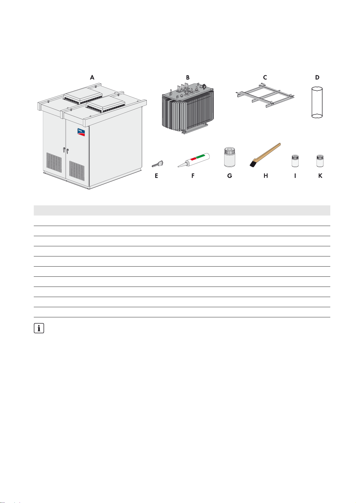
3 Scope of Delivery
Check the delivery for completeness and any visible external damage. Contact SMA Solar Technology AG if the delivery
is incomplete or damaged.
Figure1: Scope of delivery
Position Quantity Designation
A 1 Transformer Compact Station
B 1 Transformer
C 1 Guiding rail for installing the high-voltage transformer
D 3 Protection against contact for high voltage terminal of the transformer
E 1 Wrench set with two wrenches
F2Silicone cartridge
G 1 5Y7/1 color 100 ml
H1Brush
I 1 Hardener 25 ml
K 1 Thinner 50 ml
Material for live bolted connections
All high-current contacts are fitted with screws, washers, spring washers and nuts.
These are part of the scope of delivery but are not itemized separately.
When establishing live bolted connections, always use the supplied material.
Installation Manual TCS-JP-IA-en-10 9
Page 10
4 Product Description SMA Solar Technology AG
4 Product Description
4.1 System Overview
The Transformer Compact Station is a transformer unit that converts low voltage into high voltage. The
Transformer Compact Station is equipped with a low-voltage power switch and a high-voltage transformer.
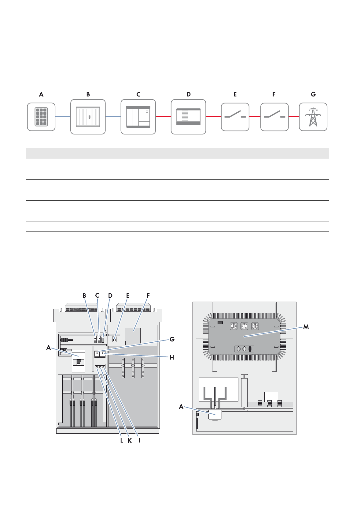
Figure2: Principle of a grid-tie PV power plant with Transformer Compact Station
Position Designation
A PV modules
B Sunny String-Monitor
C Sunny Central
D Transformer Compact Station
E High-voltage switchgear
F Point of interconnection
G Utility grid
Only Sunny Central inverters of the CP-JP production series are connected to the Transformer Compact Station.
The inverter converts the direct current into alternating current. The alternating current is then supplied to the high-voltage
transformer. The alternating current is transmitted from the high-voltage transformer to the switchgear and fed into the
utility grid.
4.2 Transformer Compact Station
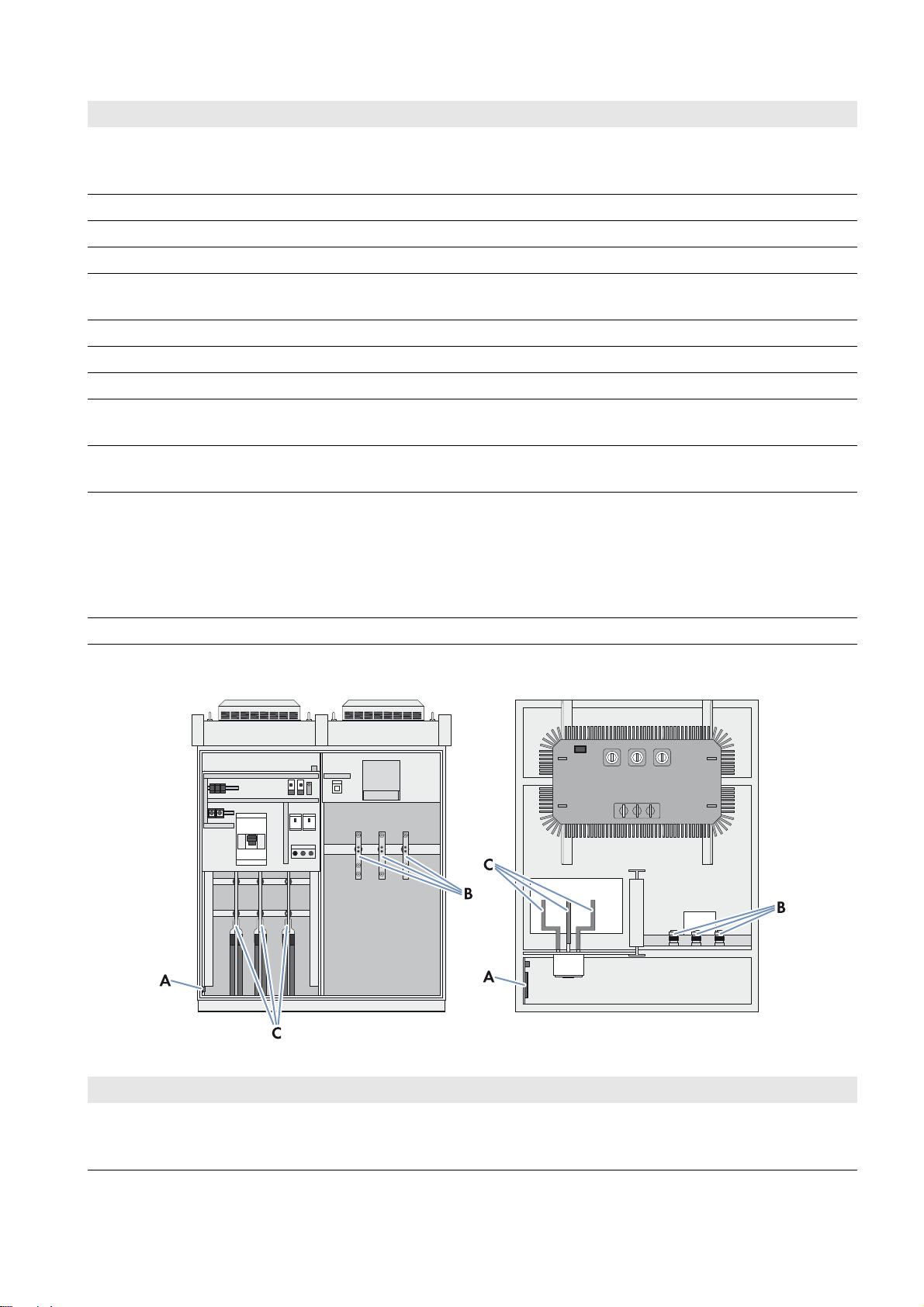
Figure3: Design of the Transformer Compact Station (front and top view)
10 TCS-JP-IA-en-10 Installation Manual
Page 11
SMA Solar Technology AG 4 Product Description
Position Designation Explanation
A Low-voltage power switch Connects the Transformer Compact Station to the inverter.
The low-voltage power switch is used to disconnect the
Transformer Compact Station from the inverter.
B Fan control contactor 50 Hz or 60 Hz
C Fan control contactor 50 Hz or 60 Hz
D Thermostat Settings for the temperature range for the fans
E Light repeater transformer alarm This light repeater indicates when the temperature of the transformer
has exceeded 100°C.
F Low-voltage transformer Transformer for supplying the station fans
G Circuit breaker for fan supply Primary protection of the low-voltage transformer
H Circuit breaker for fan supply Secondary protection of the low-voltage transformer
I Reset push button for transformer
warning
K Transformer alarm push button for
light repeater test
L Selection switch for fan control
(ON/OFF/AUTO)
By pushing this button, the transformer alarm is reset and the light
repeater (E) goes out.
By pushing the button, the functioning of the light repeater (E) can be
tested.
This selection switch sets the operating mode of the fans:
ON: fans are activated
OFF: fans are deactivated
AUTO: fans are switched on or off automatically based on
temperature
M High-voltage transformer Converts low voltage into high voltage
Connection Areas of the Transformer Compact Station
Figure4: Overview of the connection areas in the Transformer Compact Station (front and top view)
Position Designation Explanation
A Connecting terminal plate for station
supply, inverter supply and
transformer protection unit
The external voltage supply of the station as well as the supply line to
the inverter and the transformer protection signal line are connected
to this connecting terminal plate.
Installation Manual TCS-JP-IA-en-10 11
Page 12
4 Product Description SMA Solar Technology AG
Position Designation Explanation
B Connection area for high voltage Connection of the high-voltage cables that are routed to the
high-voltage switchgear
C Connection area for low voltage Connection of AC cables from the inverter
The Transformer Compact Station has doors at the front and back.
The Transformer Compact Station and the high-voltage transformer are delivered separately. After the Transformer
Compact Station is mounted, the high-voltage transformer must be installed and connected in the
Transformer Compact Station. The high-voltage transformer is to be pushed into the Transformer Compact Station via the
back of the Transformer Compact Station.
4.3 Type Label
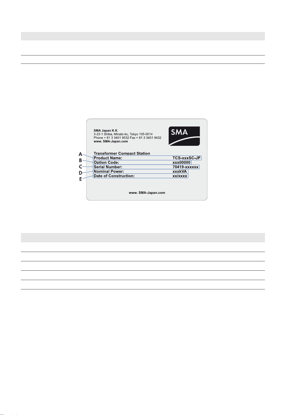
Figure5: Type label of the Transformer Compact Station
The type label is used to identify the Transformer Compact Station. The type label is located on the inside of the right-hand
door in front of the high-voltage connection area (at the front of the Transformer Compact Station). The following
information is listed on the type label:
Position Designation
A Type designation (Product Name)
B Option code
C Serial number (Serial No.)
DPower (Nominal Power)
E Date of construction
12 TCS-JP-IA-en-10 Installation Manual
Page 13
SMA Solar Technology AG 5 Mounting Location
5 Mounting Location
Requirements for the mounting location:
☐ The mounting location must be accessible at all times.
☐ The mounting location must not be higher than 1,000 m above MSL.
☐ All minimum clearances must be observed.
☐ A safety clearance of 5,000 mm from flammable objects must be maintained.
☐ All ambient conditions must be met (see Section12, page48).
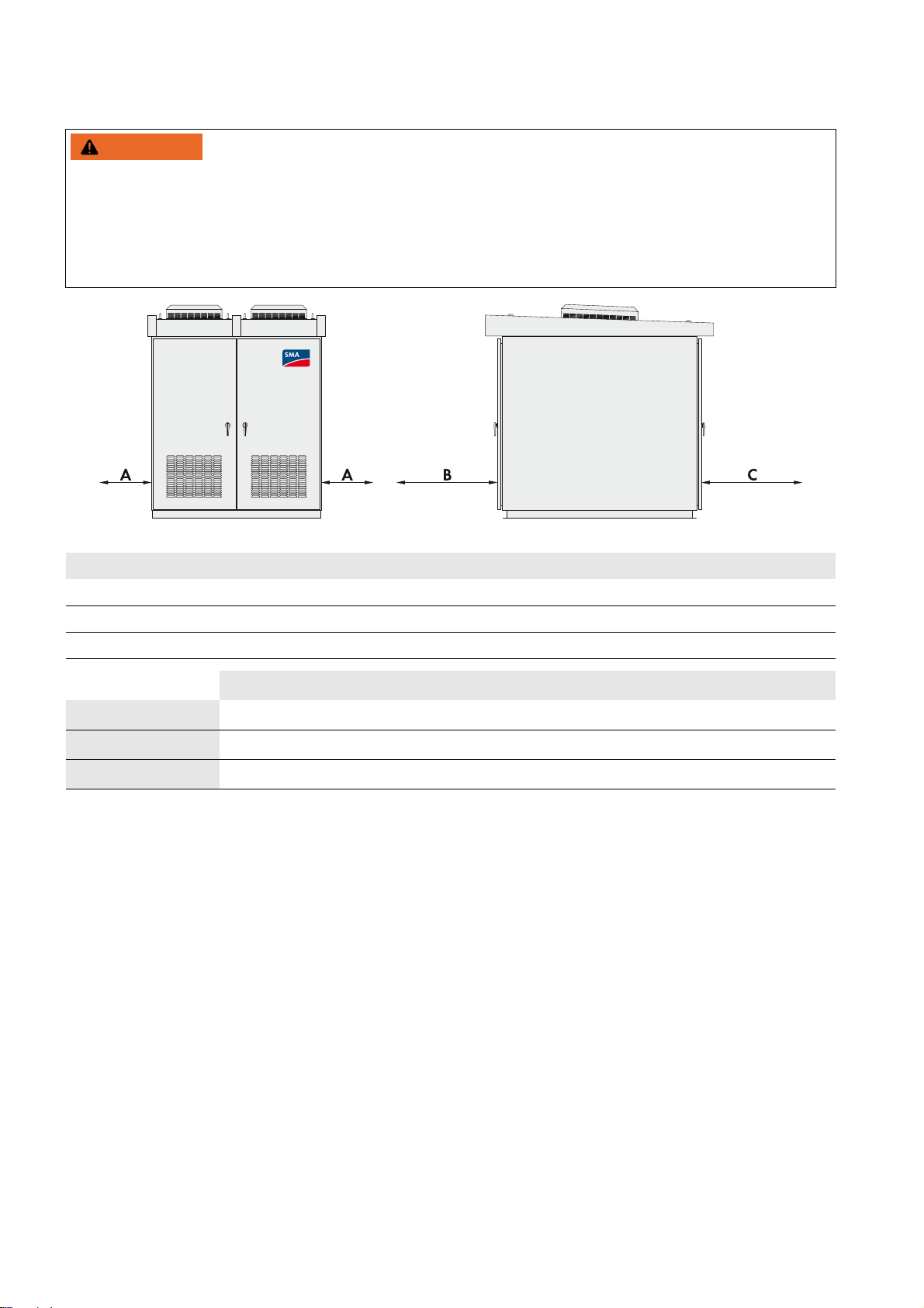
Dimensions of the Transformer Compact Station
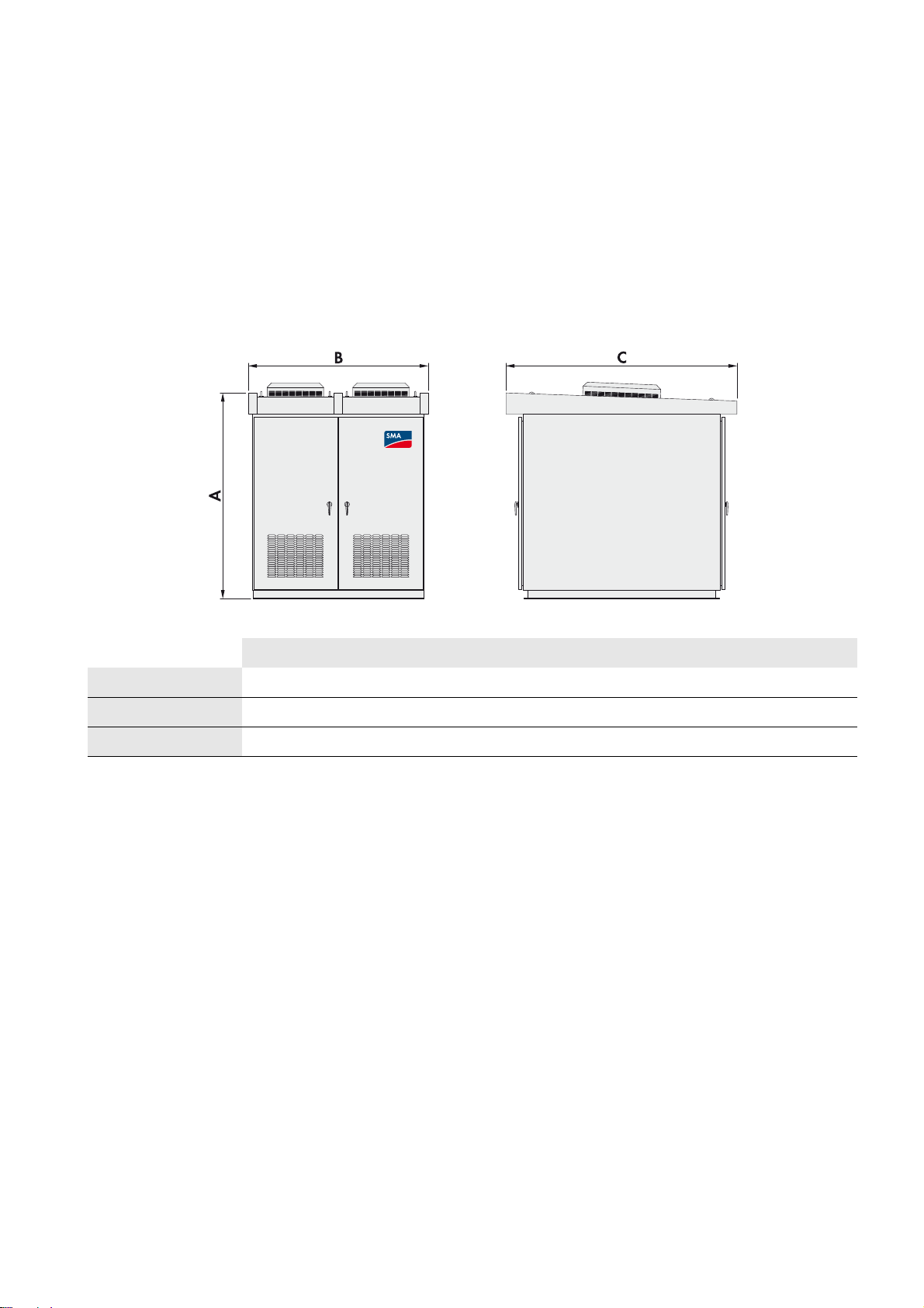
Figure6: Dimensions of the Transformer Compact Station
TCS 500SC-JP TCS 630SC-JP TCS 800SC-JP
A - height 2,517 mm 2,517 mm 2,517 mm
B - width 1,700 mm 2,100 mm 2,300 mm
C - depth 2,400 mm 2,700 mm 2,900 mm
Installation Manual TCS-JP-IA-en-10 13
Page 14
5 Mounting Location SMA Solar Technology AG
:$5 1,1*
Minimum Clearances for the Transformer Compact Station
Fire hazard due to overheating of cables
Differing cable lengths lead to overheating of the cables. Excessive heat can result in cable fires. Death or serious injury
due to fire can result.
• All line conductors from the inverter to the Transformer Compact Station must be of the same length.
• The cable length between the connection points must not exceed 15 m.
Figure7: Minimum clearances for the Transformer Compact Station
Position Designation
A Lateral minimum clearance
B Minimum clearance at the front of the Transformer Compact Station
C Minimum clearance at the back of the Transformer Compact Station
TCS 500SC-JP TCS 630SC-JP TCS 800SC-JP
A 600 mm 600 mm 600 mm
B 1,400 mm 1,600 mm 1,700 mm
C 1,700 mm 1,900 mm 2,000 mm
14 TCS-JP-IA-en-10 Installation Manual
Page 15
SMA Solar Technology AG 6 Transport and Mounting
:$5 1,1*
/05*$&
6 Transport and Mounting
6.1 Safety during Transport and Mounting
Crush hazard due to the Transformer Compact Station tipping over if not transported properly
If the Transformer Compact Station is lifted and transported too fast or without due care, it may sway or tip over.
The center of gravity of the Transformer Compact Station is not in the middle of the device.
• The means of transportation must be designed for the weight of the Transformer Compact Station.
• Do not tilt the Transformer Compact Station or the high-voltage transformer during transportation.
• Transport the Transformer Compact Station and the high-voltage transformer as close to the ground as possible.
• Always use all anchoring points during transportation.
• Avoid sudden, jerky movements during transportation.
Damage to the Transformer Compact Station due to moisture penetration
• Only transport and store the Transformer Compact Station with its doors closed.
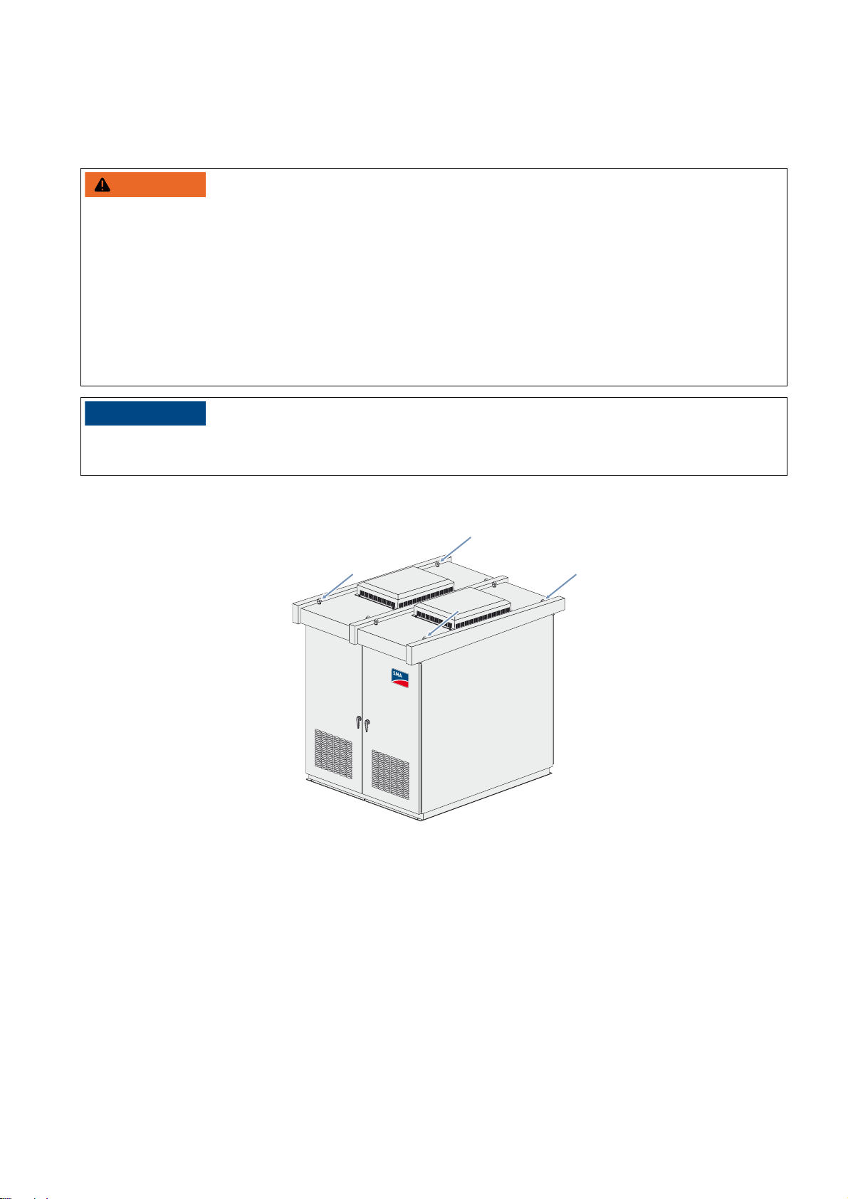
6.2 Transporting the Transformer Compact Station
Figure8: Position of the crane hooks
Requirement:
☐ The foundation of the Transformer Compact Station must be ready.
☐ The crane and hoist must be suitable for the weight of the Transformer Compact Station.
☐ The hoist must be properly connected to the crane.
☐ The angle of the chain suspension when attached to the crane hook must not exceed 60°.
Installation Manual TCS-JP-IA-en-10 15
Page 16
6 Transport and Mounting SMA Solar Technology AG
Procedure:
1. Attach the hoist to all lifting lugs on the Transformer Compact Station. Ensure that the roof of the
Transformer Compact Station is not damaged in the process.
2. Raise the crane hook slowly until the chains are taut.
3. Ensure that the hoist is attached correctly.
4. Slightly raise the Transformer Compact Station.
5. Transport the Transformer Compact Station as close to the ground as possible.
6. Transport the Transformer Compact Station to the mounting location and set down.
7. Remove the lifting equipment from the anchoring points.
8. Attach the Transformer Compact Station to the mounting surface with screws, nuts and washers.
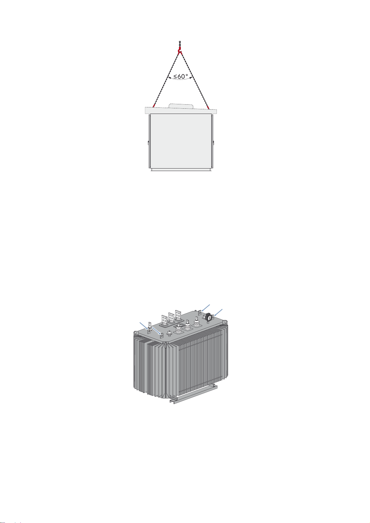
6.3 Transporting the High-Voltage Transformer
Figure9: Position of the crane hooks
Requirement:
☐ The crane and hoist must be suitable for the weight of the high-voltage transformer.
☐ The hoist must be properly connected to the crane.
☐ The angle of the chain suspension when attached to the crane hook must not exceed 60°.
16 TCS-JP-IA-en-10 Installation Manual
Page 17

SMA Solar Technology AG 6 Transport and Mounting
Procedure:
1. Attach the hoist to all lifting lugs of the high-voltage transformer. Ensure that the chains of the hoist do not touch the
low-voltage and high-voltage terminals of the transformer and that the surface of the transformer is not damaged.
2. Raise the crane hook slowly until the chains are taut.
3. Ensure that the hoist is attached correctly.
4. Slightly raise the high-voltage transformer.
5. Transport the high-voltage transformer as close to the ground as possible.
6. Transport the high-voltage transformer to the mounting location and set it down on the guiding rails provided for this
purpose at the back of the Transformer Compact Station.
7. Remove the lifting equipment from the anchoring points.
6.4 Installing the High-Voltage Transformer in the Transformer Compact Station
The high-voltage transformer must be installed in the back of the Transformer Compact Station prior to the beginning of
installation.
Figure10: Position of the high-voltage transformer before installation in the Transformer Compact Station, with guiding rails assembled
Installation Manual TCS-JP-IA-en-10 17
Page 18

6 Transport and Mounting SMA Solar Technology AG
☐ 2 screws M10x30 for fastening the guiding rails to the Transformer Compact Station
☐ 2 screws M12, nuts and washers for mounting the high-voltage transformer in the Transformer Compact Station
Procedure:
1. Open the doors at the back of the Transformer Compact Station.
2. Remove the protective cover at the back of the
Transformer Compact Station.
3. Remove the lower cross-beam in the door opening. Use a suitable
wrench for this (AF: 13).
18 TCS-JP-IA-en-10 Installation Manual
Page 19

SMA Solar Technology AG 6 Transport and Mounting
4. Attach the guiding rail to the Transformer Compact Station with
screws, washers, spring washers and nuts (torque: 24 Nm).
5. Lift the high-voltage transformer onto the guiding rails using a
crane (see Section6.3, page16). Ensure that the high-voltage
transformer is introduced into the Transformer Compact Station
with the low-voltage side first.
6. Slowly slide the high-voltage transformer into the
Transformer Compact Station up to the stop. Ensure that the
high-voltage transformer does not tip off the guiding rail.
7. Attach the fixing bracket on the beam of the high-voltage
transformer with two screws (M12), washers and nuts to the
Transformer Compact Station (torque: 41 Nm).
8. Attach the fixing bracket of the high-voltage transformer with one
screw (M16), spring washers, washers and nut to the
Transformer Compact Station (torque: 100 Nm).
9. Disassemble the guiding rail from the Transformer Compact Station and retain for subsequent replacement work.
Installation Manual TCS-JP-IA-en-10 19
Page 20

7 Electrical Connection SMA Solar Technology AG
'$1*(5
:$5 1,1*
7 Electrical Connection
7.1 Safety during Electrical Connection
Danger to life from electric shock due to live cables
Cables that are already connected to a current source may be live. Touching live cables results in death or serious injury
due to electric shock.
• Prior to connecting the cables, ensure that all DC cables are voltage-free.
• Wear suitable personal protective equipment for all work on the devices.
Risk of fire due to failure to observe torque specifications on live bolted connections
Failure to follow the specified torques reduces the ampacity of live bolted connections so that the contact resistances
increase. This can cause components to overheat and catch fire.
• Ensure that live bolted connections are always tightened with the correct torques.
• When working on the device, use suitable tools only.
• Avoid repeated tightening of live bolted connections as this may result in inadmissibly high torques.
•Always carry out electrical connections according to the circuit diagram.
7.2 Sequence of the Electrical Connection
Procedure See
1 Prepare the base plates Section 7.4, page22
2 Ground the Transformer Compact Station Section 7.6, page27
3 Ground the high-voltage transformer Section 7.7.1, page29
4 Install the connection between the low-voltage switchgear and the high-voltage
transformer
5 Install the connection between the high-voltage transformer and the high-voltage
connection busbars
6 Wire the terminals of the contact thermometer. Section 7.7.3, page31
7 Insert the cables Section 7.8, page32
8 Connect the low-voltage cables Section 7.9.2, page34
9 Connect the high-voltage cables Section 7.9.3, page34
10 Connect the internal power supply Section 7.9.4, page34
11 Connect the internal power supply of the inverter Section 7.9.5, page34
12 Connect the cables of the transformer monitoring unit Section 7.9.6, page34
Section 7.7.1, page29
Section 7.7.2, page30
13 Seal the enclosure openings Section 7.10.1, page35
14 Mount the protective covers. Section 7.10.2, page35
20 TCS-JP-IA-en-10 Installation Manual
Page 21

SMA Solar Technology AG 7 Electrical Connection
7.3 Design of the Bolted Connections
7.3.1 Connection with One Terminal Lug
Figure11: Design of the connection with terminal lug for terminals with single assignment
Position Designation
ANut
BSpring washer
CFender washer
D Copper busbar
E Tin-plated one-hole terminal lug
FScrew M12
7.3.2 Connection with Two Terminal Lugs
Figure12: Design of the connection with terminal lugs for terminals with double assignment
Installation Manual TCS-JP-IA-en-10 21
Page 22

7 Electrical Connection SMA Solar Technology AG
Position Designation
ANut
BSpring washer
CFender washer
D Tin-plated one-hole terminal lug
E Copper busbar
FScrew M12
7.4 Preparing the Base Plates
The base plates of the Transformer Compact Station must be prepared for cable entry prior to installation.
Figure13: Position of the base plate openings in the Transformer Compact Station
TCS 500SC-JP TCS 630SC-JP TCS 800SC-JP
A 1,700 mm 2,100 mm 2,300 mm
B 2,400 mm 2,700 mm 2,900 mm
C 490 mm 490 mm 490 mm
D 295 mm 370 mm 395 mm
E 95 mm 170 mm 195 mm
F 500 mm 500 mm 500 mm
22 TCS-JP-IA-en-10 Installation Manual
Page 23

SMA Solar Technology AG 7 Electrical Connection
Position Designation
AA Base plate opening for the low-voltage cables, grounding and internal power supply
BB Base plate opening for high-voltage cables
Requirements:
☐ The Transformer Compact Station must be at the final installation site.
☐ The cables must be routed in empty conduits.
Additionally required mounting material (not included in the scope of delivery):
☐ Suitable tool for punching the holes in the base plates (e.g., stamping tool)
Procedure:
1. Open the front of the Transformer Compact Station.
2. Remove the transparent protective cover from the connection area.
3. Remove the upper protective cover from the connection area.
4. Remove the lower protective cover from the connection area.
Installation Manual TCS-JP-IA-en-10 23
Page 24

7 Electrical Connection SMA Solar Technology AG
5. Remove the base plate from the opening for the low-voltage
connection.
6. Remove the base plate from the opening for the high-voltage
cables.
7. Mark the holes for the cable entries on the base plates in accordance with the cable arrangement.
8. Punch the holes.
9. Mount the base plate on the opening for the low-voltage
connection.
10. Mount the base plate on the opening for the high-voltage cables.
24 TCS-JP-IA-en-10 Installation Manual
Page 25

SMA Solar Technology AG 7 Electrical Connection
7.5 Cleaning the Live Contact Surfaces
Before live connections are connected, all contact surfaces must be cleaned thoroughly. Always proceed as described
in the following sections.
7.5.1 Important Information on Cleaning the Contact Surfaces
Make the connection as quickly as possible after cleaning
Once the contact surfaces have been cleaned, make the connection as quickly as possible in order to avoid new
contamination.
• If they are not connected after cleaning within eight hours at the latest, cleaning must be repeated.
Dispose of the cleaning cloths after one use
Lint-free cloths must be used for cleaning the contact surfaces.
• Dispose of the cloths after each cleaning.
• Never use the same cloth for contact surfaces made of different materials.
Use the correct non-woven abrasive
When sanding contact surfaces made of different materials, different non-woven abrasives must be used.
• For sanding contact surfaces made of untinned copper, always use red non-woven abrasive.
– Material number: 87-50005999.
• For sanding contact surfaces made of aluminum, always use gray non-woven abrasive.
– Material number: 87-500057611.
• Never use the same non-woven abrasive for contact surfaces made of different materials.
Wear ESD safety gloves
Fingerprints on cleaned contact surfaces cause oxidation. Oxidized contact surfaces reduce the ampacity of the live
connections.
• Always wear ESD safety gloves when cleaning contact surfaces.
7.5.2 Cleaning Untinned Copper Contact Surfaces
Requirements:
☐ Before processing the contact surfaces, make sure that no voltage is present in the components.
☐ Additionally required material must be available.
Installation Manual TCS-JP-IA-en-10 25
Page 26

7 Electrical Connection SMA Solar Technology AG
Additionally required material (not included in the scope of delivery):
☐ Non-woven abrasive, red (material number: 87-50005999)
☐ Lint-free cleaning cloth
☐Degreaser
Procedure:
1. Clean the contact surface using a clean, lint-free cloth and degreaser.
2. Sand the cleaned contact surface with red non-woven abrasive until the contact surface shines lightly. Only sand in
one direction.
3. Ensure that the entire contact surface has been correctly sanded.
4. Clean the sanded contact surface thoroughly again using a clean, lint-free cloth and degreaser.
5. Make sure that the entire contact surface has been cleaned completely.
6. Do not touch the contact surfaces again after cleaning.
7.5.3 Cleaning Tinned Contact Surfaces
Requirements:
☐ Before processing the contact surfaces, make sure that no voltage is present in the components.
☐ Additionally required material must be available.
Additionally required material (not included in the scope of delivery):
☐ Lint-free cleaning cloth
☐Degreaser
Procedure:
1. Clean the contact surface using a clean, lint-free cloth and degreaser.
2. Make sure that the entire contact surface has been cleaned completely.
3. Do not touch the contact surfaces again after cleaning.
7.5.4 Cleaning Aluminum Contact Surfaces
Requirements:
☐ Before processing the contact surfaces, make sure that no voltage is present in the components.
☐ Additionally required material must be available.
Additionally required material (not included in the scope of delivery):
☐ Non-woven abrasive, gray (material number: 87-500057611)
☐ Lint-free cleaning cloth
☐Degreaser
Procedure:
1. Clean the contact surface using a clean, lint-free cloth and degreaser.
2. Sand the cleaned contact surface with gray non-woven abrasive until it shines lightly. Only sand in one direction.
3. Ensure that the entire contact surface has been correctly sanded.
4. Clean the sanded contact surface thoroughly again using a clean, lint-free cloth and degreaser.
5. Make sure that the entire contact surface has been cleaned completely.
6. Do not touch the contact surfaces again after cleaning.
26 TCS-JP-IA-en-10 Installation Manual
Page 27
SMA Solar Technology AG 7 Electrical Connection
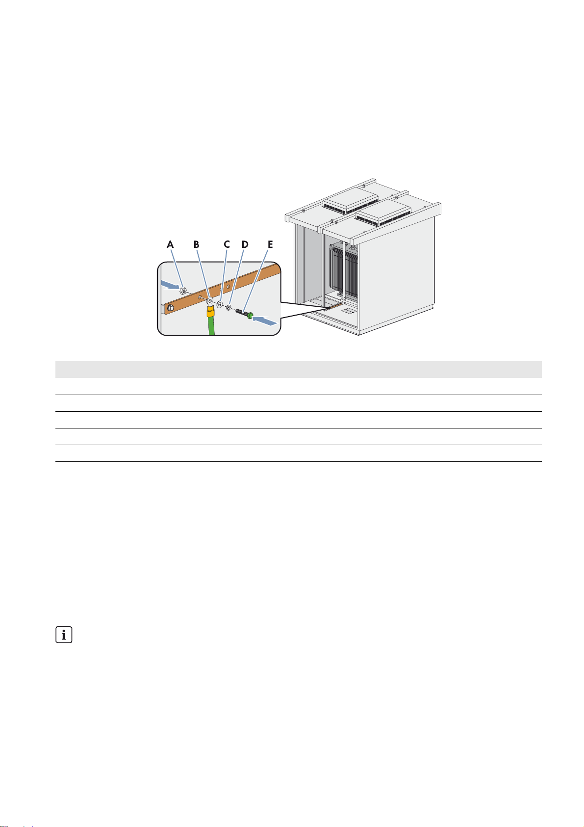
7.6 Grounding
7.6.1 Grounding the Transformer Compact Station
The Transformer Compact Station is equipped with a grounding busbar which enables external grounding.
The external grounding must be executed by the customer on site in accordance with the grounding concept of the entire
PV power plant. Influencing factors are the conditions or conductivity of the soil, the lightning protection system and the
type of ground electrode. The ground electrodes can be executed, for example, as grounding straps or grounding rods.
Figure14: Position of the grounding busbar in the Transformer Compact Station
Position Designation
ANut
B Grounding cable
CFender washer
DSpring washer
EScrew
Requirements:
☐ Additionally required mounting material must be available.
☐ Contact surfaces must have been cleaned (see Section7.5, page25).
Additionally required mounting material (not included in the scope of delivery):
☐Screw, M8
☐ Spring washer: external diameter: 29 mm, internal diameter: 13.5 mm, thickness: 1.25 mm
☐ Fender washer: external diameter: 32 mm, internal diameter: 13 mm
☐Nut
☐ Ground electrodes suitable for the grounding concept of the PV system
Grounding of the Transformer Compact Station
Ground the Transformer Compact Station in accordance with the applicable regulations.
Installation Manual TCS-JP-IA-en-10 27
Page 28
7 Electrical Connection SMA Solar Technology AG
Procedure:
1. Install the ground electrodes in accordance with the applicable regulations.
2. Ensure that the required grounding resistance is achieved.
3. Clean the contact surfaces (see Section7.5, page25).
4. Mount the grounding cable to the grounding busbar using screw, nut and washers.
5. Tighten the bolted connection at the grounding connection (torque: 12 Nm).
6. Check that the grounding cable is correctly connected.
7. Connect the grounding cables to the grounding busbar.
8. Connect the grounding cables to the ground electrode.
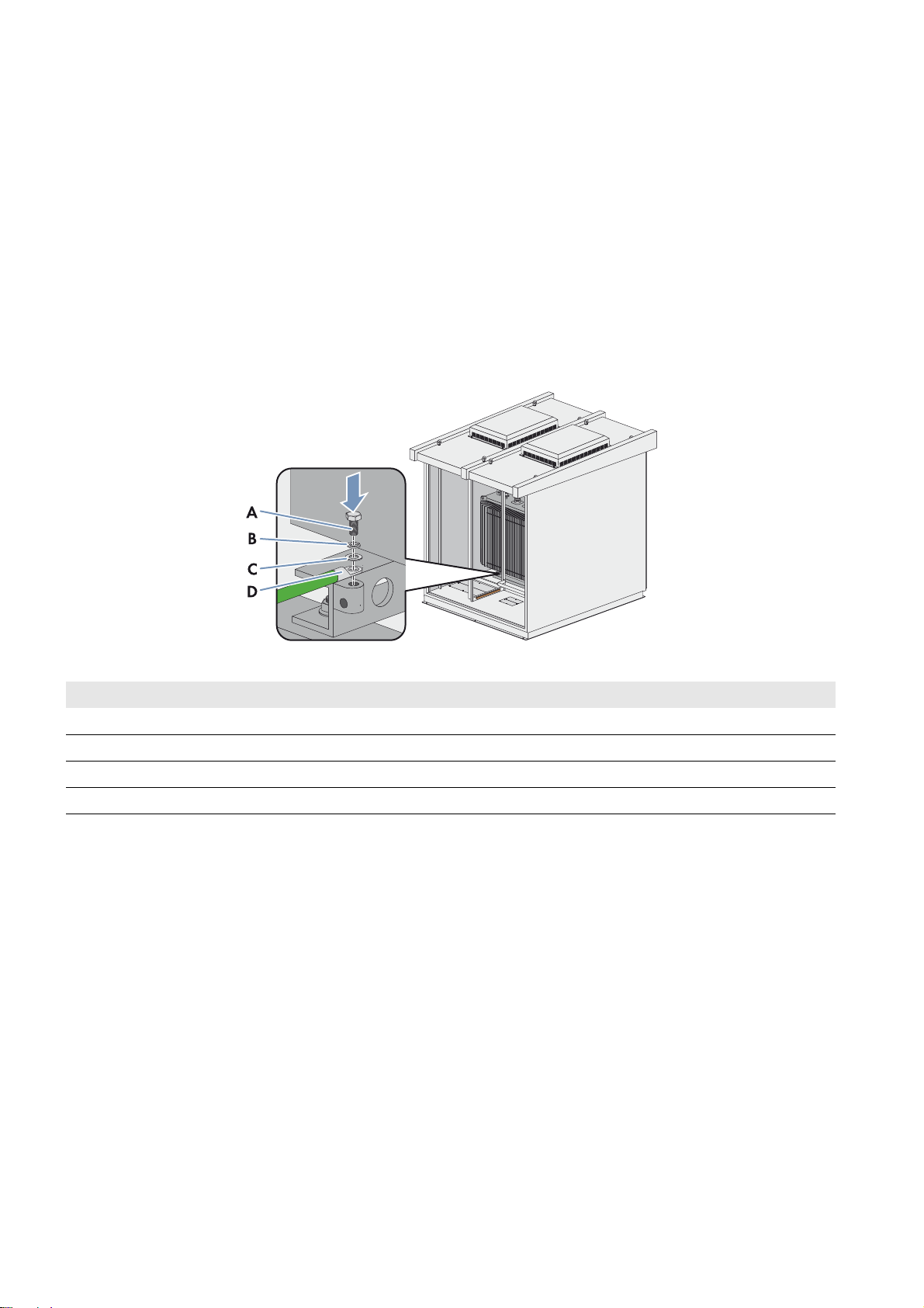
7.6.2 Grounding the High-Voltage Transformer
Figure15: Position of the grounding bolt on the high-voltage transformer
Position Designation
AScrew
BSpring washer
CFender washer
D Grounding cable
Procedure:
1. Clean the contact surfaces (see Section7.5, page25).
2. Connect the grounding cable to the grounding bolt of the high-voltage transformer with screw and washers
(torque: 37 Nm).
3. Check that the grounding cable is correctly connected.
28 TCS-JP-IA-en-10 Installation Manual
Page 29
SMA Solar Technology AG 7 Electrical Connection
7.7 Connecting the High-Voltage Transformer to the Transformer Compact Station
Once the high-voltage transformer has been installed in the Transformer Compact Station, it must be connected to the
Transformer Compact Station. The connections on the Transformer Compact Station are prepared upon delivery.
The prepared terminals must be used exclusively for the connection between the low-voltage power switch and the
transformer.
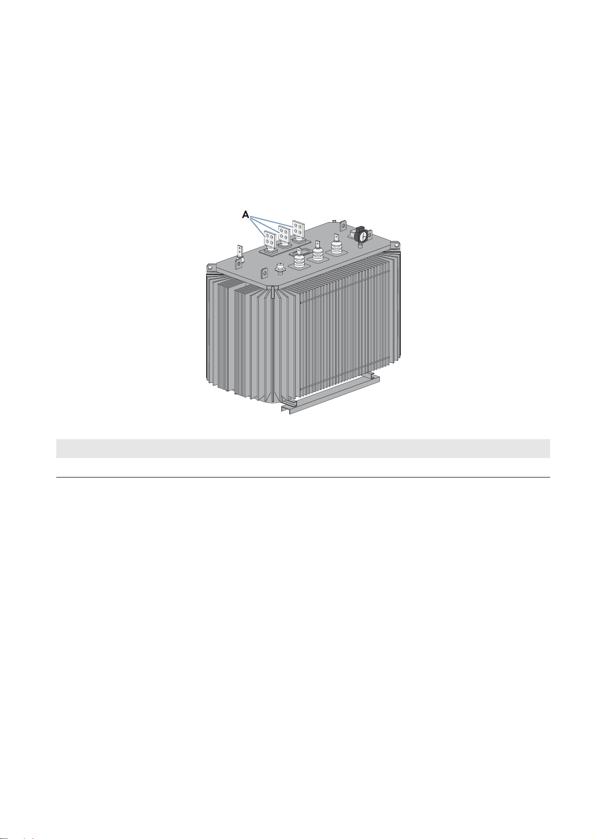
7.7.1 Installing the Connection between the Low-Voltage Power Switch and the
High-Voltage Transformer
Figure16: Low-voltage connection area of the Transformer Compact Station
Position Designation
A Low-voltage connection area
Requirements:
☐ The Transformer Compact Station must be mechanically anchored to the support surface
(see Section6.3, page16).
☐ The grounding of the high-voltage transformer must be connected (see Section7.7.1, page29).
Procedure:
1. Clean the contact surfaces (see Section7.5, page25).
2. C onnect the cables coming from the low-voltage power switc h to the low-voltage side of the high-voltage transformer
with screws, nuts and washers (torque: 37 Nm).
3. Ensure that the connections are correctly made.
Installation Manual TCS-JP-IA-en-10 29
Page 30
7 Electrical Connection SMA Solar Technology AG
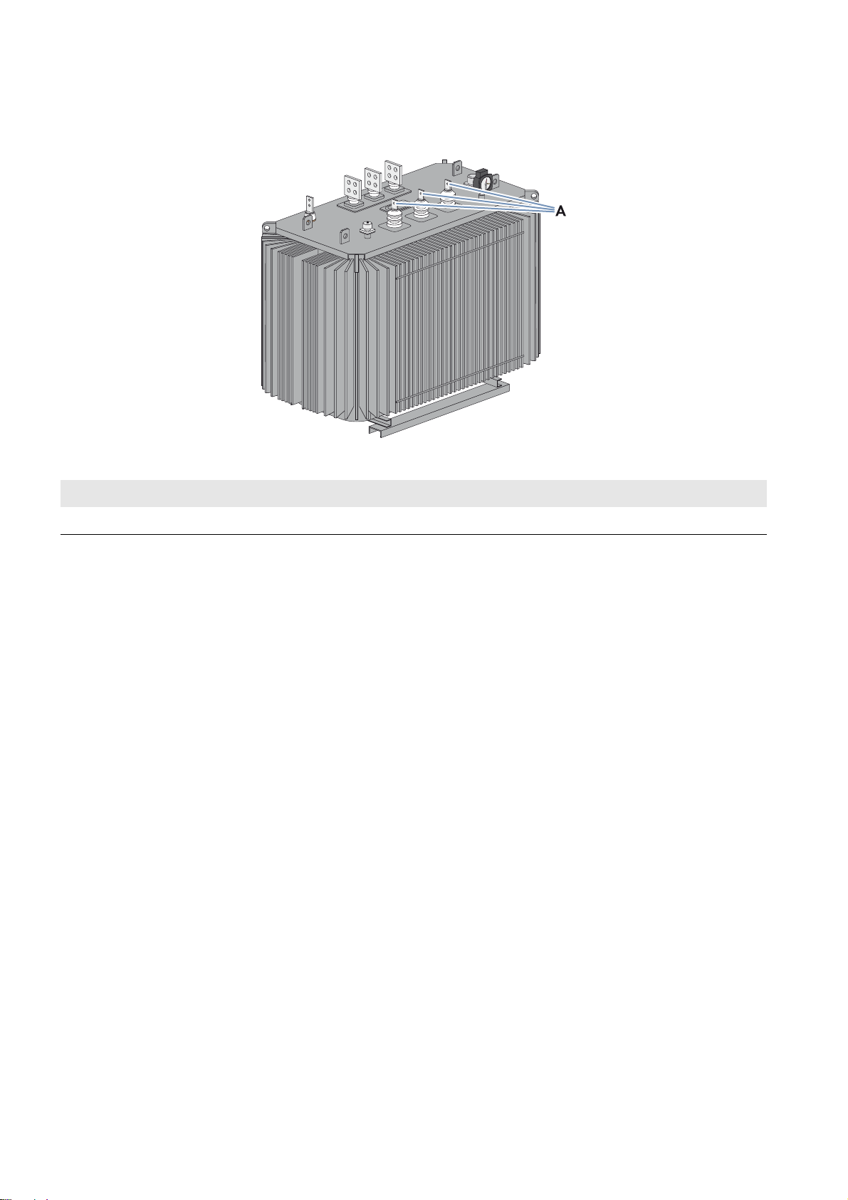
7.7.2 Installing the Connection between the High-Voltage Transformer and the High-Voltage Connection Busbars
Figure17: High-voltage connection area of the Transformer Compact Station
Position Designation
A High-voltage connection area
Requirements:
☐ The Transformer Compact Station must be anchored to the support surface (see Section6.3, page16).
☐ The grounding of the high-voltage transformer must be connected (see Section7.7.1, page29).
☐ The high-voltage transformer must be connected to the low-voltage power switch (see Section7.7.1, page29).
Procedure:
1. Clean the contact surfaces (see Section7.5, page25).
2. Lead the cables through the protection against contact.
3. Connect the cables coming from the high-voltage connection busbars to the high-voltage side of the high-voltage
transformer with screws, nuts and washers (torque: 37 Nm). Pay attention to the colored labeling of the cables.
4. Ensure that the connections are correctly made.
5. Slide the protection against contact over the connection points.
30 TCS-JP-IA-en-10 Installation Manual
Page 31
SMA Solar Technology AG 7 Electrical Connection
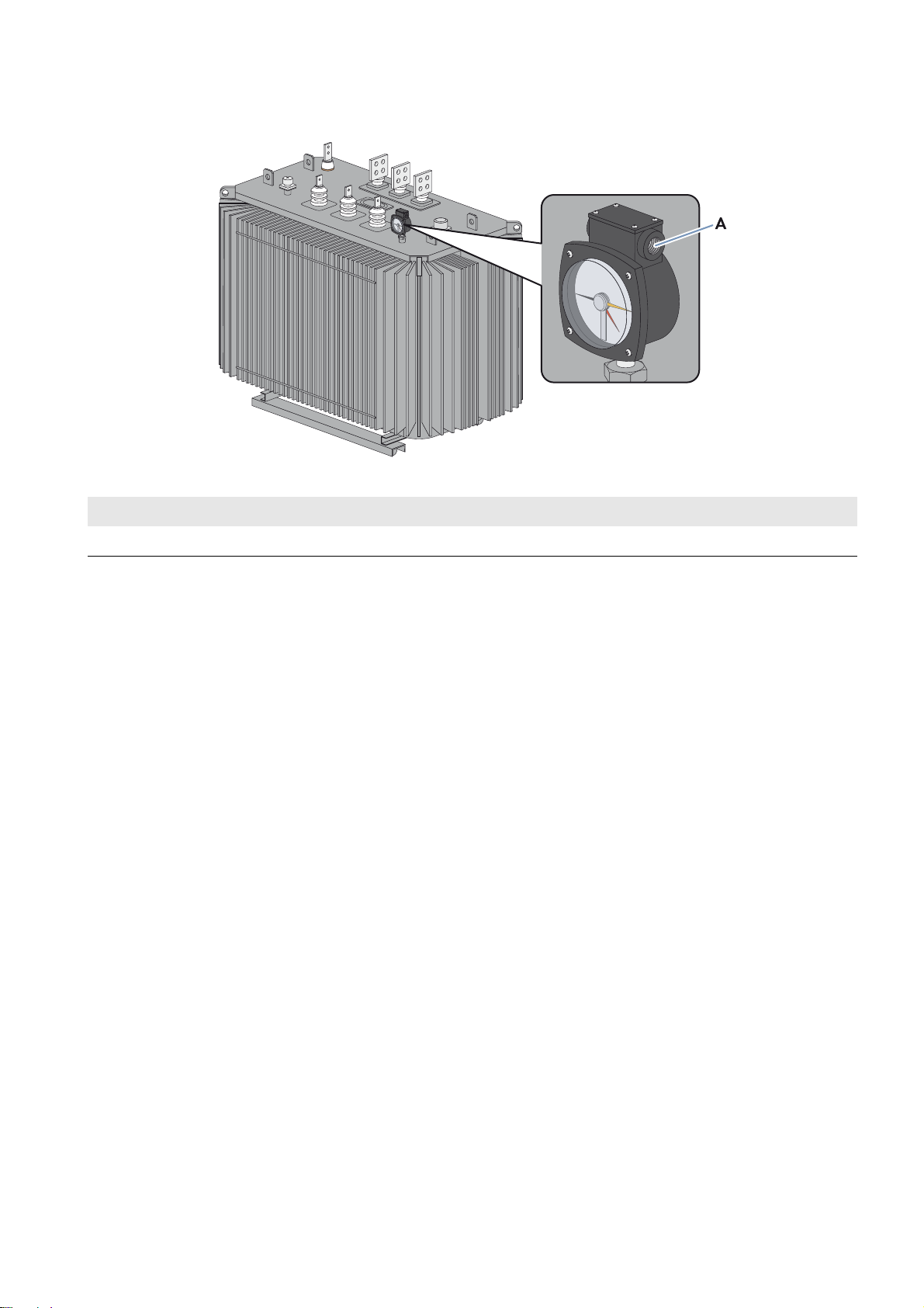
7.7.3 Installing the Contact Thermometer Connections
Figure18: Contact thermometer of the high-voltage transformer
Position Designation
A Contact thermometer
Requirements:
☐ The Transformer Compact Station must be anchored to the support surface (see Section6.3, page16).
☐ The grounding of the high-voltage transformer must be connected (see Section7.7.1, page29).
☐ The high-voltage transformer must be connected to the low-voltage power switch (see Section7.7.1, page29).
☐ The high-voltage transformer must be connected to the high-voltage connection area (see Section7.7.2, page30).
Procedure:
1. Using a cross-head screwdriver, unscrew the four screws (M4) of the cover.
2. Remove the cover with seal and safely store it along with the screws.
3. Insert the cable into the contact thermometer sideways.
4. Connect the cable to the terminal of the contact thermometer with screws, nuts and washers in accordance with the
circuit diagram (torque: 1.57 Nm).
5. Ensure that the connection is correctly made.
6. Mount the seal and cover and tighten all four screws using a cross-head screwdriver (torque: 1.4 Nm).
Installation Manual TCS-JP-IA-en-10 31
Page 32

7 Electrical Connection SMA Solar Technology AG
7.8 Inserting the AC Cables
Requirement for cable routing:
☐ The low-voltage cables are bundled in the three-phase system.
☐ Between the low-voltage power switch and the inverter, there are, depending on the design, three or four separate
cable routes (e.g., cable channels) for the AC cables. Note that after building the foundation and positioning the
Transformer Compact Station, it will be necessary to excavate cavities underneath the foundation for the cables to
be laid to the enclosure openings.
☐ The space between the cable routes must be at least twice the diameter of an AC cable.
Figure19: Arrangement of AC cables with four cables per line conductor (example).
Observe cable clearances
Lay one line conductor L1, L2 and L3 in each low-voltage cable route. Ensure that the space between the cable
bundles is at least double that of the diameter of a cable. This will prevent the cables from overheating.
Alternate swapping of the line conductors L1 and L3 prevents current imbalances.
Procedure:
1. Clean the contact surfaces (see Section7.5, page25).
2. Insert the cables in the Transformer Compact Station:
– Cables connecting the high-voltage switchgear to the grid-connection point
– Cables connecting the low-voltage power switch to the inverter
– Cables for the internal power supply of the inverter
– Cables of the transformer protection unit
– Cable for the external supply voltage of the Transformer Compact Station
32 TCS-JP-IA-en-10 Installation Manual
Page 33

SMA Solar Technology AG 7 Electrical Connection
7.9 Cable Connection
7.9.1 Connection Areas of the Transformer Compact Station
Figure20: Overview of the connection areas in the Transformer Compact Station (front and top view)
Detailed View of the Connecting Terminal Plate for Inverter Supply, Fan Supply and Transformer
Protection Unit
Figure21: Detailed view of the connecting terminal plate for inverter supply, fan supply and transformer protection unit
Position Designation Explanation
A Station supply Clamping area for the voltage supply to the station
B Inverter supply Clamping area for the voltage supply to the inverter
C Signal terminal for the transformer
protection unit
D Reserve Reserve
Clamping area for the signal cables of the transformer protection unit
Installation Manual TCS-JP-IA-en-10 33
Page 34

7 Electrical Connection SMA Solar Technology AG
7.9.2 Connecting the Low-Voltage Cables
If you are using the preassembled cable set from SMA Solar Technology AG, the cables are fitted with terminal lugs and
can be used without any further preparatory work. If you are not using the cable set from SMA Solar Technology AG,
the AC cables will need to be fitted with terminal lugs prior to use.
Procedure:
1. If you are using non-SMA cables, strip off the insulation of the low-voltage cables.
2. If you are not using the preassembled cables, fit the cables with terminal lugs.
3. Clean the contact surfaces (see Section7.5, page25).
4. Connect the low-voltage cables to the connection busbars in accordance with the circuit diagram (torque: 37 Nm).
7.9.3 Connecting the High-Voltage Cables
1. Strip off the insulation of the high-voltage cables.
2. Fit terminal lugs to the high-voltage cables.
3. Clean the contact surfaces (see Section7.5, page25).
4. Connect the high-voltage cables to the connection busbars according to the circuit diagram (torque: 37 Nm).
7.9.4 Connecting the External Supply Voltage
1. Insert the cable of the external voltage supply through the base plate in the low-voltage connection area.
2. Strip off the insulation of the external voltage supply cable by approx. 10 mm.
3. Fit one bootlace ferrule to the external voltage supply cable.
4. Connect the external voltage supply cable to the terminal (see circuit diagram).
5. Secure the cable of the external voltage supply on the cable support rail. This will prevent the cable from being
pulled out inadvertently.
7.9.5 Connecting the Cable for the Internal Power Supply of the Inverter
1. Insert the cable of the inverter voltage supply through the base plate in the low-voltage connection area.
2. Strip off the insulation of the voltage supply cable of the inverter by approx. 10 mm.
3. Fit one bootlace ferrule to the voltage supply cable of the inverter.
4. Connect the voltage supply cable of the inverter to the terminal (see circuit diagram).
5. Secure the voltage supply cable of the inverter on the cable support rail. This will prevent the cable from being pulled
out inadvertently.
7.9.6 Connecting the Inverter to the Output Terminal of the Transformer Protection
Unit in the Transformer
1. Insert the cable of transformer protection unit through the base plate in the low-voltage connection area.
2. Strip off the insulation of the cable of the transformer protection unit by approximately 10 mm.
3. Place a bootlace ferrule on the cable of the transformer protection unit.
4. Connect the cable of the transformer protection unit to terminal xx.
Compact Station
5. Secure the cable of the transformer protection unit on the cable support rail. This will prevent the cable from being
pulled out inadvertently.
34 TCS-JP-IA-en-10 Installation Manual
Page 35

SMA Solar Technology AG 7 Electrical Connection
7.10 Final Installation Work
7.10.1 Sealing the Base Plates
Once installation work is completed, the base plates must be sealed. This will protect the Transformer Compact Station
from moisture ingress.
Additionally required mounting material (not included in the scope of delivery):
☐ Suitable material for sealing the base plates (e.g. putty)
Procedure:
• Seal the base plates of the Transformer Compact Station. Make sure not to damage the cable insulation.
7.10.2 Mounting the Protective Covers
Once installation work is completed or if protracted interruptions are anticipated during installation, the protective covers
must be mounted.
Procedure:
1. Mount the cross-beam at the high-voltage transformer with two screws (M8) and tighten the screws (torque: 12 Nm).
2. Mount the protective covers at the high-voltage connection area with six screws (M6) each and tighten the screws
(torque: 2.5 Nm).
3. Attach the protective cover for the connection area of the low-voltage power switch with four screws (M6) and
tighten the screws (torque: 5 Nm).
4. Attach the protective cover for the high-voltage connection area with four screws (M6) and tighten the screws
(torque: 5 Nm).
Installation Manual TCS-JP-IA-en-10 35
Page 36

8 Commissioning SMA Solar Technology AG
'$1*(5
:$5 1,1*
8 Commissioning
8.1 Safety during Commissioning
Danger to life from electric shock due to live voltages
High voltages are present in the Transformer Compact Station. Touching live components results in death or serious
injury due to electric shock.
• When working on the Transformer Compact Station, always wear suitable personal protective equipment.
• Do not touch any live components.
• Follow the instructions precisely.
• Observe all warning messages on the product and in the documentation.
• Before performing any work on the Transformer Compact Station, ensure that no voltage is present in any of the
devices.
• Ensure that no disconnected devices can be reconnected.
• Ground and short-circuit the Transformer Compact Station.
• Cover or isolate any adjacent live components.
Risk of fire due to faulty connection
• Switch off all switching elements:
– Switch off the low-voltage power switch (see documentation of the low-voltage power switch).
– Switch off the high-voltage switchgear (see documentation of the high-voltage switchgear).
– Remove the fuses.
– Switch off the circuit breakers.
36 TCS-JP-IA-en-10 Installation Manual
Page 37

SMA Solar Technology AG 8 Commissioning
8.2 Commissioning the Transformer Compact Station
Statutory warranty and guarantee claims
Statutory warranty and guarantee claims can only be made valid if initial commissioning was carried out by
SMA Solar Technology AG or providing that the completed and signed "Initial Commissioning Report for
Sunny Central Systems" is on file at SMA Solar Technology AG. The commissioning report is included in the scope
of delivery of the Sunny Central.
Figure22: Design of the Transformer Compact Station (front and top view)
Position Designation Explanation
A Low-voltage power switch Connects the Transformer Compact Station to the inverter.
The low-voltage power switch is used to disconnect the
Transformer Compact Station from the inverter.
B Fan control contactor 50 Hz or 60 Hz
C Fan control contactor 50 Hz or 60 Hz
D Thermostat Settings for the temperature range for the fans
E Light repeater transformer alarm This light repeater indicates when the temperature of the transformer
has exceeded 100°C.
F Low-voltage transformer Transformer for supplying the station fans
G Circuit breaker for fan supply Primary protection of the low-voltage transformer
H Circuit breaker for fan supply Secondary protection of the low-voltage transformer
I Reset push button for transformer
warning
K Transformer alarm push button for
light repeater test
L Selection switch for fan control
(ON/OFF/AUTO)
By pushing this button, the transformer alarm is reset and the light
repeater (E) goes out.
By pushing the button, the functioning of the light repeater (E) can be
tested.
This selection switch sets the operating mode of the fans:
ON: fans are activated
OFF: fans are deactivated
AUTO: fans are switched on or off automatically based on
temperature
M High-voltage transformer Converts low voltage into high voltage
Installation Manual TCS-JP-IA-en-10 37
Page 38

8 Commissioning SMA Solar Technology AG
Requirements
☐ The high-voltage switchgear must be switched off.
☐ The low-voltage power switch must be switched off.
☐ All terminals must be connected in accordance with the manuals and the circuit diagram (see Section7 "Electrical
Connection", page20).
Procedure:
1. Check the cabling in the Transformer Compact Station (see Section8.4, page39).
2. Make sure the temperature settings on the contact thermometer of the high-voltage transformer are correct:
– Warning temperature: +100°C
3.
4.
5. Check the AC low voltage at the low-voltage power switch (see Section8.4, page39).
6. Switch on the low-voltage power switch.
7. Commission the inverter (see inverter documentation).
Only a duly authorized person trained in electrical safety is allowed to connect the AC voltage of
the high-voltage transformer.
Have the AC voltage of the high-voltage transformer connected externally.
Only a duly authorized person is allowed to switch on the high-voltage switchgear.
Switch on the high-voltage switchgear (see documentation of the high-voltage switchgear).
8.3 Checking the Cabling in the Transformer Compact Station
1. Ensure that all connections have been made in accordance with the circuit diagram.
2. Ensure that all connections are securely in place.
3. Check the equipotential bonding of the Transformer Compact Station to the mounting location. Connect if necessary.
38 TCS-JP-IA-en-10 Installation Manual
Page 39

SMA Solar Technology AG 8 Commissioning
8.4 Checking the AC Low Voltage at the Low-Voltage Power Switch
1. Check the low voltage for the right-hand rotating magnetic field. Correct if necessary.
2. Measure the low voltage between the line conductors and log in the commissioning report.
–L
- L
1
2
–L1 - L
–L2 - L
☑ The low voltage is within ± 5 V of the nominal voltage of the inverter.
✖ Does the low voltage vary from the nominal voltage of the inverter by more than ± 5 V?
• Disconnect the high-voltage transformer from voltage sources.
• Have a duly authorized person adjust the conversion ratio of the high-voltage transformer by the tap changer.
☑ The tap changer clicks into place.
• Proceed to Step 2.
3
3
Installation Manual TCS-JP-IA-en-10 39
Page 40

9 Disconnecting and Reconnecting SMA Solar Technology AG
'$1*(5
9 Disconnecting and Reconnecting
9.1 Safety during Disconnection and Reconnection
Danger to life from electric shock due to live voltage
High voltages are present in the Transformer Compact Station. Touching live components results in death or serious
injury due to electric shock.
• When working on the Transformer Compact Station, always wear suitable personal protective equipment.
• Do not touch any live components.
• Follow the instructions precisely.
• Observe all warning messages on the product and in the documentation.
• Before performing any work on the Transformer Compact Station, ensure that no voltage is present in any of the
devices.
• Ensure that no disconnected devices can be reconnected.
• Ground and short-circuit the Transformer Compact Station.
• Cover or isolate any adjacent live components.
• After switching the inverter off, wait 15 minutes before opening it. This allows the capacitors to discharge.
Connecting and disconnecting high voltage
Only a duly authorized person trained in electrical safety is allowed to connect and disconnect the AC voltage.
9.2 Disconnection
1. Switch off the inverter. Turn the key switch to Stop (see inverter installation manual).
2. Wait 15 minutes before opening the inverter. This allows the capacitors to discharge.
3. Switch the AC power switch in the inverter off (see inverter installation manual).
4. Switch off the high-voltage switchgear (see documentation of the high-voltage switchgear).
5. Close the grounding switch of the high-voltage switchgear (see documentation of the high-voltage switchgear).
6. Attach labels with the name of the duly authorized person to the high-voltage switchgear.
7. Ensure that all poles are free of voltage.
8. Ensure that no connection points can be accidentally reconnected.
9.3 Reconnection
1. Remove labels with the name of the duly authorized person from the high-voltage switchgear.
2. Open the grounding switch of the high-voltage switchgear (see documentation of the high-voltage switchgear).
3. Switch on the high-voltage switchgear (see documentation of the high-voltage switchgear).
4. Switch on the AC power switch in the inverter (see inverter installation manual).
5. Switch on the inverter. Turn the key switch to Start (see inverter installation manual).
40 TCS-JP-IA-en-10 Installation Manual
Page 41

SMA Solar Technology AG 10 Maintenance
'$1*(5
/05*$&
10 Maintenance
10.1 Safety during Maintenance
Danger to life from electric shock due to live voltage
High voltages are present in the Transformer Compact Station. Touching live components results in death or serious
injury due to electric shock.
• When working on the Transformer Compact Station, always wear suitable personal protective equipment.
• Do not touch any live components.
• Follow the instructions precisely.
• Observe all warning messages on the product and in the documentation.
• Before any work is performed, always disconnect the following components from voltage sources if live voltage is
not absolutely necessary:
– Low-voltage power switch
– External high-voltage switchgear
• Ensure that no disconnected devices can be reconnected.
• Before performing any work on the Transformer Compact Station, ensure that no voltage is present in any of the
devices.
• Ground and short-circuit the Transformer Compact Station.
• Cover or isolate any adjacent live components.
Danger to life from electric shock if the Transformer Compact Station is damaged
Operating a damaged Transformer Compact Station can lead to hazardous situations that result in death or serious
injuries due to electric shock.
• Operate the Transformer Compact Station only if it is technically safe and in good working order.
• Regularly check the Transformer Compact Station for visible damage.
• Make sure that all external safety equipment is freely accessible at all times.
• Make sure that all safety equipment is in good working order.
• When working on the Transformer Compact Station, always wear suitable personal protective equipment.
Damage to the devices due to sand, dust or moisture penetration
Sand, dust or moisture penetration can damage the devices of the Transformer Compact Station or impair their
functionality.
• Do not open the Transformer Compact Station during a sandstorm, precipitation or when humidity exceeds 95%.
• Only perform maintenance work on the Transformer Compact Station when the environment is dry and free of
sand and dust.
Installation Manual TCS-JP-IA-en-10 41
Page 42
10 Maintenance SMA Solar Technology AG
10.2 Maintenance Schedule
10.2.1 Notes on the Maintenance Work
Compliance with the specified maintenance intervals will ensure trouble-free operation of the
Transformer Compact Station.
Adverse ambient conditions
Location and ambient conditions influence the maintenance intervals. In particular, cleaning and corrosion protection
work may be required more frequently depending on the conditions at the installation site.
• If the PV power plant is subject to adverse ambient conditions, it is recommended to shorten the maintenance
intervals.
Consumables and maintenance materials
This document only lists those consumables and maintenance materials that are not part of the standard equipment
of an electrically qualified person. Standard tools and materials such as torque wrenches, voltage detectors and
wrenches are required equipment for all maintenance operations.
Maintenance work on the high-voltage transformer must be performed according to the documentation of the
high-voltage transformer.
10.2.2 Monthly Maintenance Work
Task See
Optical Inspection Section 10.3.1, page42
Checking the Latches, Door Stops and Hinges Section 10.3.2, page43
Checking the Transformer Compact Station for Corrosion Section 10.3.4, page44
Checking the Fans Section 10.3.5, page44
10.2.3 Maintenance Work Every 6 Months
Task See
Cleaning the Interior Section 10.3.6, page45
Checking the Seals Section 10.3.7, page45
Checking the Bolted Connections of the Power Cabling Section 10.4.1, page46
Checking the Bolted Connections on the Transformer Compact Station Section 10.4.2, page47
10.3 General Maintenance
10.3.1 Optical Inspection
1. Check the Transformer Compact Station for visual defects such as discoloration, dirt, damage and scratches on the
enclosure. If visual defects are present, repair these immediately.
2. Make sure that the protective covers are in place and undamaged. Clean soiled protective covers and eliminate any
defects immediately.
3. Ensure that there are no objects on or in the Transformer Compact Station that are flammable or that could otherwise
endanger the operational safety of the Transformer Compact Station.
4. Make sure that the enclosure openings are protected from penetration by foreign bodies (e.g., animals or leaves).
If the enclosure openings are not adequately sealed, renew the sealing material.
42 TCS-JP-IA-en-10 Installation Manual
Page 43

SMA Solar Technology AG 10 Maintenance
'$1*(5
5. Ensure that there is no moisture inside the Transformer Compact Station. If there is moisture inside the
Transformer Compact Station, remove it. Be sure to observe the safety information.
6. Ensure that the fans in the Transformer Compact Station are working properly and that the fan guards are free of
dust and dirt deposits. If the fans are not working properly, contact the SMA Service Line.
7. Check whether any warning labels or warning signs are missing or damaged.
Replace any warning labels and signs that are missing or damaged. Contact the SMA Service Line.
8. Make sure that the Transformer Compact Station is freely accessible and that all minimum clearances are complied
with.
10.3.2 Checking the Latches, Door Stops and Hinges
Danger to life from electric shock due to incorrectly disconnected Transformer Compact Station
If the Transformer Compact Station and its devices are not correctly disconnected, dangerous voltages may be present
in the components which, if touched, will result in death or serious injury.
• Disconnect the Transformer Compact Station from voltage sources (see Section9, page40).
• Ensure that the Transformer Compact Station and its devices are voltage-free.
Additionally required maintenance material (not included in the scope of delivery):
☐ A suitable anhydrous, temperature-resistant lubricant, e.g., WD40
☐ Non-greasing antifreeze agent, e.g. PS88
Procedure:
1. Check whether the doors latch easily. Open and close the doors several times.
If the doors do not latch easily, lubricate all moving parts of the latch.
2. Check whether the stops hold the doors in place.
If the doors are not arrested, lubricate the door stops.
3. Check whether the door hinges move easily.
If the door hinges do not move easily, lubricate the hinges.
4. Lubricate all moving parts and movement points.
5. Tighten any loose screws with the specified torque.
6. If the Transformer Compact Station is installed in regions with sub-zero temperatures, apply non-greasing antifreeze
agent to the profile cylinder of the door locks and the key switches to protect them from icing up.
10.3.3 Testing the Inlet Filters
1. Check the inlet filters in the doors of the Transformer Compact Station for contamination.
2. Replace the inlet filters if they are severely contaminated.
• Turn the fixing cross counterclockwise until the cross and the inlet filter can be removed from the bracket.
• Replace the inlet filters.
• Insert the fixing cross and turn clockwise into the bracket.
Installation Manual TCS-JP-IA-en-10 43
• Ensure that the inlet filter and the fixing cross are securely in place.
Page 44

10 Maintenance SMA Solar Technology AG
'$1*(5
10.3.4 Checking the Transformer Compact Station for Corrosion
Additionally required maintenance material (not included in the scope of delivery):
☐ Use touch-up sticks, paint brushes, cans of spray paint or, alternatively, 2K-PUR acrylic paint in the color 5Y7/1
(similar to RAL 7032) to repair small-area surface damage. Observe the relevant instructions of the paint
manufacturer.
☐ Use touch-up paint or, alternatively, 2K-PUR acrylic paint in the color 5Y7/1 (similar to RAL 7032) to repair
large-area surface damage. Observe the relevant instructions of the paint manufacturer.
☐ Abrasive cloth
☐Degreaser
Danger to life from electric shock due to incorrectly disconnected Transformer Compact Station
If the Transformer Compact Station and its devices are not correctly disconnected, dangerous voltages may be present
in the components which, if touched, will result in death or serious injury.
• Disconnect the Transformer Compact Station from voltage sources (see Section9, page40).
• Ensure that the Transformer Compact Station and its devices are voltage-free.
Procedure:
1. Check surfaces for damage or corrosion.
If the surfaces are damaged, repair them without delay or within three weeks at the latest.
If the surfaces are corroded, repair them without delay or within three weeks at the latest.
2. Remove dirt from the areas affected.
3. Repair damaged surfaces. In case of small-area surface damage, treat the affected area; in case of extensive
damage, treat the entire surface:
• Sand the affected area.
• Clean the affected area with degreaser.
• Paint the affected area.
10.3.5 Checking the Fans
Figure23: Position of the fan thermostat
Position Designation
AFan thermostat
44 TCS-JP-IA-en-10 Installation Manual
Page 45
SMA Solar Technology AG 10 Maintenance
'$1*(5
'$1*(5
Procedure:
1. Open the doors of the Transformer Compact Station.
2. Set the fan thermostat to a temperature below the ambient temperature.
☑ The fans start up.
✖ The fans do not start up?
• Contact the SMA Service Line.
3. Reset the fan thermostat to its original position.
4. Close the doors of the Transformer Compact Station.
10.3.6 Cleaning the Interior
Danger to life from electric shock due to incorrectly disconnected Transformer Compact Station
If the Transformer Compact Station and its devices are not correctly disconnected, dangerous voltages may be present
in the components which, if touched, will result in death or serious injury.
• Disconnect the Transformer Compact Station from voltage sources (see Section9, page40).
• Ensure that the Transformer Compact Station and its devices are voltage-free.
Procedure:
1. Ensure that the Transformer Compact Station is disconnected.
2. Ensure that the seal of the switch cabinet is intact.
3. Remove dirt and dust from the interior of the switch cabinet and from all assemblies (e.g. low-voltage power switch).
4. Check the interior for leaks.
If leaks are present, eliminate them.
10.3.7 Checking the Seals
Danger to life from electric shock due to incorrectly disconnected Transformer Compact Station
If the Transformer Compact Station and its devices are not correctly disconnected, dangerous voltages may be present
in the components which, if touched, will result in death or serious injury.
• Disconnect the Transformer Compact Station from voltage sources (see Section9, page40).
• Ensure that the Transformer Compact Station and its devices are voltage-free.
Procedure:
1. Check whether there is any damage to the seals in the sealing edges. Note: the sealing area is not visible when the
door is closed.
Installation Manual TCS-JP-IA-en-10 45
If seals are damaged, contact the SMA Service Line.
Page 46

10 Maintenance SMA Solar Technology AG
'$1*(5
:$5 1,1*
/05*$&
10.4 Electrical and Mechanical Maintenance
10.4.1 Checking the Bolted Connections of the Power Cabling
Danger to life from electric shock due to incorrectly disconnected Transformer Compact Station
If the Transformer Compact Station and its devices are not correctly disconnected, dangerous voltages may be present
in the components which, if touched, will result in death or serious injury.
• Disconnect the Transformer Compact Station from voltage sources (see Section9, page40).
• Ensure that the Transformer Compact Station and its devices are voltage-free.
Risk of fire due to failure to observe torque specifications on live bolted connections
Failure to follow the specified torques reduces the ampacity of live bolted connections so that the contact resistances
increase. This can cause components to overheat and catch fire.
• Ensure that live bolted connections are always tightened with the specified torque.
• When working on the device, use suitable tools only.
• Avoid repeated tightening of live bolted connections as this may result in inadmissibly high torques.
Damage to bolted connections if the permitted torques are exceeded
Tightening bolted connections that have already reached their permitted torque can damage these connections.
• Only tighten loose bolted connections to the prescribed torque. Contact the SMA Service Line if specifications are
missing.
Procedure:
• Check that all bolted connections are tight.
If any bolted connections are loose, tighten them with a torque wrench. Always adhere to the torque specifications.
• Check the insulation and connections for discoloration and signs of wear.
If the insulation or connections are discolored or show signs of wear, contact the SMA Service Line.
46 TCS-JP-IA-en-10 Installation Manual
Page 47
SMA Solar Technology AG 11 Disposal
'$1*(5
:$5 1,1*
/05*$&
10.4.2 Checking the Bolted Connections on the Transformer Compact Station
Danger to life from electric shock due to incorrectly disconnected Transformer Compact Station
If the Transformer Compact Station and its devices are not correctly disconnected, dangerous voltages may be present
in the components which, if touched, will result in death or serious injury.
• Disconnect the Transformer Compact Station from voltage sources (see Section9, page40).
• Ensure that the Transformer Compact Station and its devices are voltage-free.
Risk of fire due to failure to observe torque specifications on live bolted connections
Failure to follow the specified torques reduces the ampacity of live bolted connections so that the contact resistances
increase. This can cause components to overheat and catch fire.
• Ensure that live bolted connections are always tightened with the specified torque.
• When working on the device, use suitable tools only.
• Avoid repeated tightening of live bolted connections as this may result in inadmissibly high torques.
Damage to bolted connections if the permitted torques are exceeded
Tightening bolted connections that have already reached their permitted torque can damage these connections.
• Only tighten loose bolted connections to the prescribed torque. Contact the SMA Service Line if specifications are
missing.
Procedure:
• Check whether each bolted connection on the Transformer Compact Station and the high-voltage transformer is
tight.
If any bolted connections are loose, tighten them with a torque wrench. Always adhere to the torque specifications.
After completion of maintenance work, mount all protective covers
Once maintenance work is completed, all protective covers must be remounted.
11 Disposal
Proper disposal
Transformer Compact Stations which have come to the end of their service life constitute electronic waste. Electronic
waste contains on the one hand valuable materials which can be recycled as secondary raw materials, and on the
other, substances which are hazardous to the environment. Contact your local commercial disposal services for
information on optimum material recycling.
Installation Manual TCS-JP-IA-en-10 47
Page 48

12 Technical Data SMA Solar Technology AG
12 Technical Data
12.1 Transformer Compact Station 500SC-JP
Electrical Data
Suitable for inverter type SC 500CP-10-JP
Rated power at 25°C 500 kVA
Nominal power at 40°C 455 kVA
Nominal voltage 6,600 V
Configurable grid voltages 6,150 V / 6,300 V / 6,450 V / 6,600 V / 6,750 V
Maximum output current 14.5 A
Power frequency 50 Hz or 60 Hz
Nominal input voltage 205 V
Maximum input current 1,411 A
Transformer vector group Yd1
Dimensions and Weight
Width x height x depth 1,700 mm x 2,440 mm x 2,360 mm
Weight ∼ 5.0 t
Ambient Conditions
Ambient temperature − 20°C to +40°C
Maximum relative humidity 15% to 85%
Maximum operating altitude above MSL 1,000 m
Degree of protection IP23D
Wind and snow loads in accordance with Japanese Building Code, JEM, JIS
Seismic requirements in accordance with JSIA - N0005 2011.04.01
seismic class A
Color
Enclosure wall 5Y7/1 (similar to RAL 7032)
48 TCS-JP-IA-en-10 Installation Manual
Page 49

SMA Solar Technology AG 12 Technical Data
12.2 Transformer Compact Station 630SC-JP
Electrical Data
Suitable for inverter type SC 630CP-10-JP
Rated power at 25°C 700 kVA
Nominal power at 40°C 630 kVA
Nominal voltage 6,600 V
Configurable grid voltages 6,150 V / 6,300 V / 6,450 V / 6,600 V / 6,750 V
Maximum output current 18.2 A
Power frequency 50 Hz or 60 Hz
Nominal input voltage 315 V
Maximum input current 1,283 A
Transformer vector group Dy11
Dimensions and Weight
Width x height x depth 1,700 mm x 2,440 mm x 2,360 mm
Weight ∼ 7.3 t
Ambient Conditions
Ambient temperature − 20°C to 40°C
Maximum relative humidity 15% to 85%
Maximum operating altitude above MSL 1,000 m
Degree of protection IP23D
Wind and snow loads in accordance with Japanese Building Code, JEM, JIS
Seismic requirements in accordance with JSIA - N0005 2011.04.01
seismic class A
Color
Enclosure wall 5Y7/1 (similar to RAL 7032)
Installation Manual TCS-JP-IA-en-10 49
Page 50

12 Technical Data SMA Solar Technology AG
12.3 Transformer Compact Station 800SC-JP
Electrical Data
Suitable for inverter type SC 800CP-10-JP
Rated power at 25°C 880 kVA
Nominal power at 40°C 800 kVA
Nominal voltage 6,600 V
Configurable grid voltages 6,150 V / 6,300 V / 6,450 V / 6,600 V / 6,750 V
Maximum output current 77 A
Power frequency 50 Hz or 60 Hz
Nominal input voltage 360 V
Maximum input current 1,411 A
Transformer vector group Dy11
Dimensions and Weight
Width x height x depth 1,700 mm x 2,440 mm x 2,360 mm
Weight ∼ 8.5 t
Ambient Conditions
Ambient temperature − 20°C to 40°C
Maximum relative humidity 15% to 85%
Maximum operating altitude above MSL 1,000 m
Degree of protection IP23D
Wind and snow loads in accordance with Japanese Building Code, JEM, JIS
Seismic requirements in accordance with JSIA - N0005 2011.04.01
seismic class A
Color
Enclosure wall 5Y7/1 (similar to RAL 7032)
50 TCS-JP-IA-en-10 Installation Manual
Page 51

SMA Solar Technology AG 13 Contact
13 Contact
If you have technical problems concerning our products, contact your service partner. Your service partner needs the
following information in order to provide you with the necessary assistance:
• Serial number of the Transformer Compact Station
• Type designation of the Transformer Compact Station
• Address of the mounting location
Installation Manual TCS-JP-IA-en-10 51
Page 52

SMA Solar Technology
www.SMA-Solar.com
 Loading...