

Page 1
EN
Accessories for Central inverter
TRANSFORMER COMPACT STATION
500SC/630SC/800SC/1000SC/1250SC/1600SC
Installation Manual
TCS-IT-IEN103610 | 98-4041110 | Version 1.0
Page 2

Page 3

SMA Solar Technology AG Table of Contents
Table of Contents
1 Information on this Manual. . . . . . . . . . . . . . . . . . . . . . . . . 5
2 Security . . . . . . . . . . . . . . . . . . . . . . . . . . . . . . . . . . . . . . . . . 7
2.1 Intended Use. . . . . . . . . . . . . . . . . . . . . . . . . . . . . . . . . . . . . . . . 7
2.2 Target Group Qualification . . . . . . . . . . . . . . . . . . . . . . . . . . . . 7
2.3 Safety Instructions . . . . . . . . . . . . . . . . . . . . . . . . . . . . . . . . . . . . 8
3 Product Description . . . . . . . . . . . . . . . . . . . . . . . . . . . . . . 10
3.1 Transformer Compact Station . . . . . . . . . . . . . . . . . . . . . . . . . . 10
3.1.1 Low-Voltage Switchgear . . . . . . . . . . . . . . . . . . . . . . . . . . . . . . . . . . . . . . . . 10
3.1.2 Internal Power Supply Transformer . . . . . . . . . . . . . . . . . . . . . . . . . . . . . . . . 11
3.1.3 Medium-voltage switchgear . . . . . . . . . . . . . . . . . . . . . . . . . . . . . . . . . . . . . 11
3.1.4 Medium-voltage Transformers. . . . . . . . . . . . . . . . . . . . . . . . . . . . . . . . . . . . 11
3.1.5 Communit . . . . . . . . . . . . . . . . . . . . . . . . . . . . . . . . . . . . . . . . . . . . . . . . . . . 11
3.1.6 GSE Meter . . . . . . . . . . . . . . . . . . . . . . . . . . . . . . . . . . . . . . . . . . . . . . . . . . 11
3.1.7 Type Label. . . . . . . . . . . . . . . . . . . . . . . . . . . . . . . . . . . . . . . . . . . . . . . . . . . 11
4 Scope of Delivery. . . . . . . . . . . . . . . . . . . . . . . . . . . . . . . . 12
5 Installation Site . . . . . . . . . . . . . . . . . . . . . . . . . . . . . . . . . . 13
5.1 Choosing an Installation Site . . . . . . . . . . . . . . . . . . . . . . . . . . 13
6 Transport and Installation . . . . . . . . . . . . . . . . . . . . . . . . . 15
7 Electrical Connection . . . . . . . . . . . . . . . . . . . . . . . . . . . . . 17
7.1 Set up Electrical Connection . . . . . . . . . . . . . . . . . . . . . . . . . . . 17
7.2 Laying cables . . . . . . . . . . . . . . . . . . . . . . . . . . . . . . . . . . . . . . 18
7.2.1 Running Cables between the Low-Voltage Switchgear and the Inverter. . . . 18
7.2.2 Inserting the Cables. . . . . . . . . . . . . . . . . . . . . . . . . . . . . . . . . . . . . . . . . . . . 19
7.3 Connecting Cables . . . . . . . . . . . . . . . . . . . . . . . . . . . . . . . . . . 20
7.3.1 Connection Area of the Station Sub-Distribution Board . . . . . . . . . . . . . . . . 20
7.3.2 Connecting Cables for Inverter's Internal Power Supply. . . . . . . . . . . . . . . . 21
7.3.3 Connecting Protective Conductors . . . . . . . . . . . . . . . . . . . . . . . . . . . . . . . . 21
Installation Manual TCS-IT-IEN103610 3
Page 4

Table of Contents SMA Solar Technology AG
7.3.4 Connecting Inverter to Output Terminal of Transformer Protection
Unit in Station Sub-Distribution Board . . . . . . . . . . . . . . . . . . . . . . . . . . . . . . 22
7.3.5 Connecting Cables for the Internal Power Supply of the Transformer
Compact Station . . . . . . . . . . . . . . . . . . . . . . . . . . . . . . . . . . . . . . . . . . . . . . 23
7.4 Set Voltage on Internal Power Supply Transformer . . . . . . . . . 24
8 Commissioning . . . . . . . . . . . . . . . . . . . . . . . . . . . . . . . . . . 25
8.1 Commissioning the Transformer Compact Station . . . . . . . . . . 25
8.2 Inspecting Cabling to the Transformer Compact Station . . . . . 28
8.3 Examining Low AC Voltage in Low-Voltage Switchgear. . . . . . 28
8.4 Connecting the Internal Power Supply for the Transformer
Compact Station . . . . . . . . . . . . . . . . . . . . . . . . . . . . . . . . . . . . 28
8.5 Connecting the Internal Power Supply for the Inverter . . . . . . . 29
9 Technical Data . . . . . . . . . . . . . . . . . . . . . . . . . . . . . . . . . . 30
9.1 Transformer Compact Station 500SC. . . . . . . . . . . . . . . . . . . . 30
9.2 Transformer Compact Station 630SC. . . . . . . . . . . . . . . . . . . . 31
9.3 Transformer Compact Station 800SC. . . . . . . . . . . . . . . . . . . . 32
9.4 Transformer Compact Station 1000SC . . . . . . . . . . . . . . . . . . 33
9.5 Transformer Compact Station 1250SC . . . . . . . . . . . . . . . . . . 35
9.6 Transformer Compact Station 1600SC . . . . . . . . . . . . . . . . . . 36
10 Contact . . . . . . . . . . . . . . . . . . . . . . . . . . . . . . . . . . . . . . . . 38
4 TCS-IT-IEN103610 Installation Manual
Page 5
SMA Solar Technology AG 1Information on this Manual
1 Information on this Manual
Validity
This manual covers the following devices:
• Transformer Compact Station 500SC-IT
• Transformer Compact Station 630SC-IT
• Transformer Compact Station 800SC-IT
• Transformer Compact Station 1000SC-IT
• Transformer Compact Station 1250SC-IT
• Transformer Compact Station 1600SC-IT
Target Group
This manual is intended for skilled workers. Only qualified personnel are allowed to perform the tasks
set forth in this manual (see section 2.2"Target Group Qualification",page7).
Additional Information
Additional information is available at www.SMA.de/en:
Title Document Type
Installation requirements for the Italian station concept
Transformer Compact Stations 500SC/630SC/800SC/1000SC/
1250SC/1600SC
Technical information
Installation Manual TCS-IT-IEN103610 5
Page 6
1Information on this Manual SMA Solar Technology AG
%"/(&3
8"3/*/(
$"65*0/
/05*$&
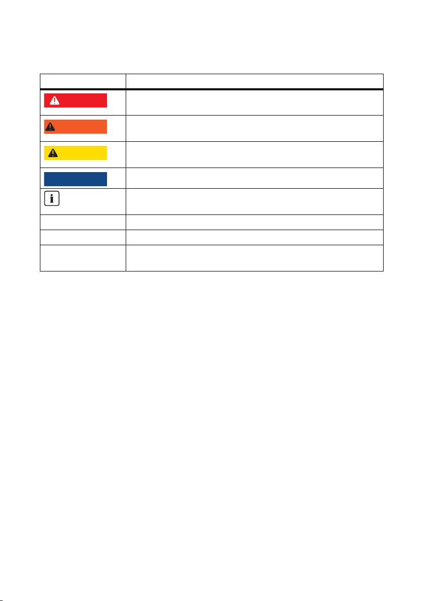
Symbols
Symbol Explanation
Indicates a hazardous situation which, if not avoided, will result in death
or serious injury.
Indicates a hazardous situation which, if not avoided, could result in death
or serious injury.
Indicates a hazardous situation which, if not avoided, could result in minor
or moderate injury.
Indicates a situation that can result in property damage if not avoided.
Indicates information that is important for a specific topic or objective, but
is not safety-relevant.
☐ Indicates a requirement for meeting a specific goal.
☑ Desired result.
✖ Undesired result. The undesired event is followed by a solution on how to
achieve the desired result.
Nomenclature
In this manual, Transformer Compact Stations 500SC-IT/630SC-IT/800SC-IT/1000SC-IT/
1250SC-IT/1600SC-IT are collectively referred to as the Transformer Compact Station.
In this manual, Sunny Central CP inverters are referred to as Sunny Central or inverters.
6 TCS-IT-IEN103610 Installation Manual
Page 7
SMA Solar Technology AG 2Security
A
B
C
D
E
S
U
N
N
Y
C
E
N
T
R
A
L
8
0
0
C
P
SM
A
2Security
2.1 Intended Use
The Transformer Compact Station is a transformer unit that steps up low voltage to medium voltage.
The Transformer Compact Station contains low-voltage switchgear and, depending on the options
ordered, may also contain medium-voltage switchgear.
The Transformer Compact Station may be connected to CP inverters in the same power class only.
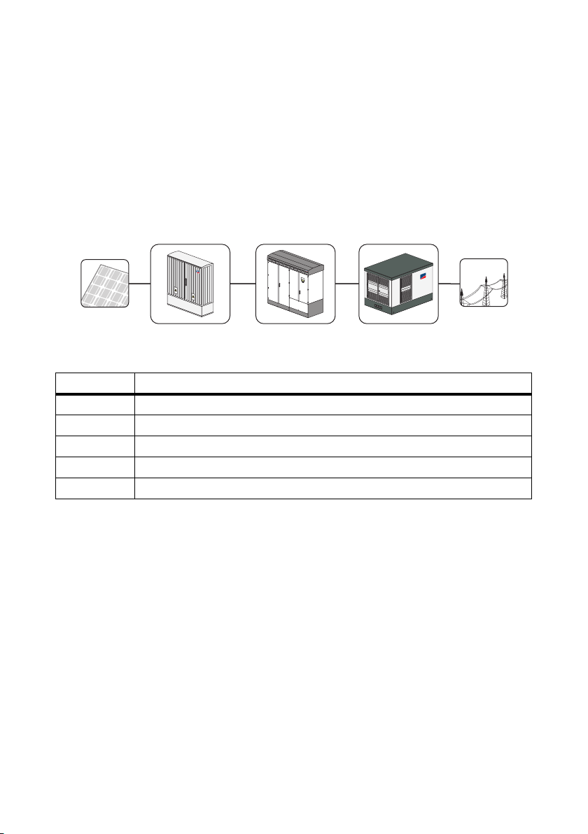
Figure1: Principle of a grid-tied PV plant with a Transformer Compact Station
Position Description
APV modules
B Sunny String-Monitor
C Sunny Central
D Transformer Compact Station
E Power distribution grid
Any use not described as intended use or any unauthorized addition or conversion may pose an
operational hazard and will void the warranty and operating license.
2.2 Target Group Qualification
Only properly qualified technical personnel may work on the equipment. "Properly qualified" means
the personnel have undergone relevant vocational training and are familiar with the contents of this
manual.
Installation Manual TCS-IT-IEN103610 7
Page 8

2Security SMA Solar Technology AG
2.3 Safety Instructions
Electric Shock
Hi gh v olt age s ar e pr ese nt i n th e Tr ans for mer Com pac t St ati on. The Tra nsf orm er C omp act Sta tio n mu st
be de-energized before any work is performed on it. All work must comply with the applicable
guidelines for the installation site.
• Disconnecting the device:
– Low-voltage switchgear
– Medium-voltage switchgear
– External voltage supply
• Ensure that the device cannot be reconnected.
• Ensure that no voltage is present in the system.
• Ground and short-circuit.
• Cover or safeguard any adjacent live components.
Operating a damaged Transformer Compact Station may cause serious injury from electric shock.
• Operate the Transformer Compact Station only if it is in safe and good working order.
• Operate the Transformer Compact Station only if there is no visible damage, and regularly
inspect it for visible damage. Ensure that all external safety equipment is freely accessible at all
times and is regularly checked for proper functioning.
Tampering with the device may cause potentially fatal injuries or property damage due to electric
shock.
• Do not operate the Transformer Compact Station while the door is open.
• Always lock the Transformer Compact Station.
• Remove the keys from the door locks.
• Keep the keys in a safe place.
Failure to follow this manual and the operating or safety instructions it contains may lead to severe
injury from electric shock.
• Only perform work as described in this manual. Observe all safety instructions.
• Establish all electrical connections according to the circuit diagram.
• Keep the documentation for the Transformer Compact Station and for the installed components
with the system documentation. They must be accessible at all times.
8 TCS-IT-IEN103610 Installation Manual
Page 9

SMA Solar Technology AG 2Security
Burn Hazard
Some components, such as fuses, can become hot during operation.
• Wear safety gloves while working on the device.
Installation Manual TCS-IT-IEN103610 9
Page 10
3Product Description SMA Solar Technology AG
3 Product Description
3.1 Transformer Compact Station
The Transformer Compact Station is a transformer unit that steps up low voltage to medium voltage.
The Transformer Compact Station contains low-voltage switchgear and, depending on the options
ordered, may also contain medium-voltage switchgear.
The Transformer Compact Station is connected to CP inverters in the same power class. Inverters
convert direct current to alternating current. The alternating current is then supplied to the transformer.
The alternating current is transmitted from the transformer to the switchgear and fed into the power
distribution grid.
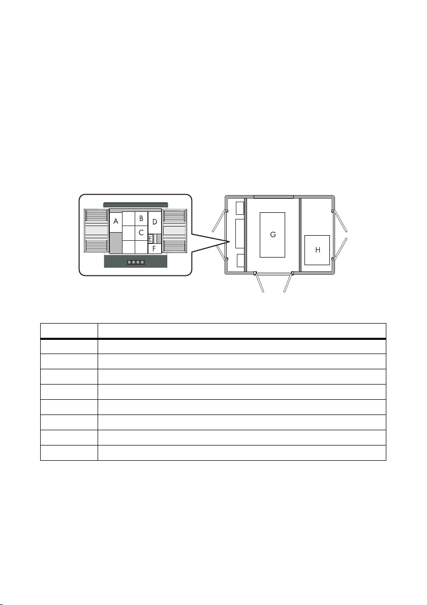
Figure2: Assembly
Position Description
A Communit communication distribution box
B GSE meter
*
*
C Low-voltage switchgear
D Station sub-distribution
E Disconnector for internal power supply transformer
F Internal power supply transformer
*
*
G Medium-voltage Transformers
H Medium-voltage switchgear
*
Optional
*
3.1.1 Low-Voltage Switchgear
The low-voltage switchgear connects the Transformer Compact Station to the inverters. The lowvoltage switchgear can be used to disconnect the Transformer Compact Station from the inverters.
10 TCS-IT-IEN103610 Installation Manual
Page 11

SMA Solar Technology AG 3Product Description
3.1.2 Internal Power Supply Transformer
The internal power supply transformer supplies power to the Transformer Compact Station and the
inverter. Supply voltage is 230 V/400 V (3/N/PE)
3.1.3 Medium-voltage switchgear
The medium-voltage switchgear is used to disconnect the Transformer Compact Station from the
medium-voltage power grid.
3.1.4 Medium-voltage Transformers
The medium-voltage transformer steps up low voltages to medium voltages.
3.1.5 Communit
The Communit communication distribution box is used to hold and cable all the communication
components used in large PV plants with Sunny Central, Sunny Mini Central, or Sunny Tripower.
3.1.6 GSE Meter
This Gestore dei Servizi Elettrici meter is used to meter energy consumption on the low-voltage side of
the transformer and to receive Conto Energia feed-in tariffs.
3.1.7 Type Label
The type label is used to identify the Transformer Compact Station. The type label is located inside to
the right on the low-voltage side. The information listed on the type label includes the following:
•Type designation
•Serial number
• Date of manufacture
Installation Manual TCS-IT-IEN103610 11
Page 12
4Scope of Delivery SMA Solar Technology AG
A
B
CD F
G
SMA
E
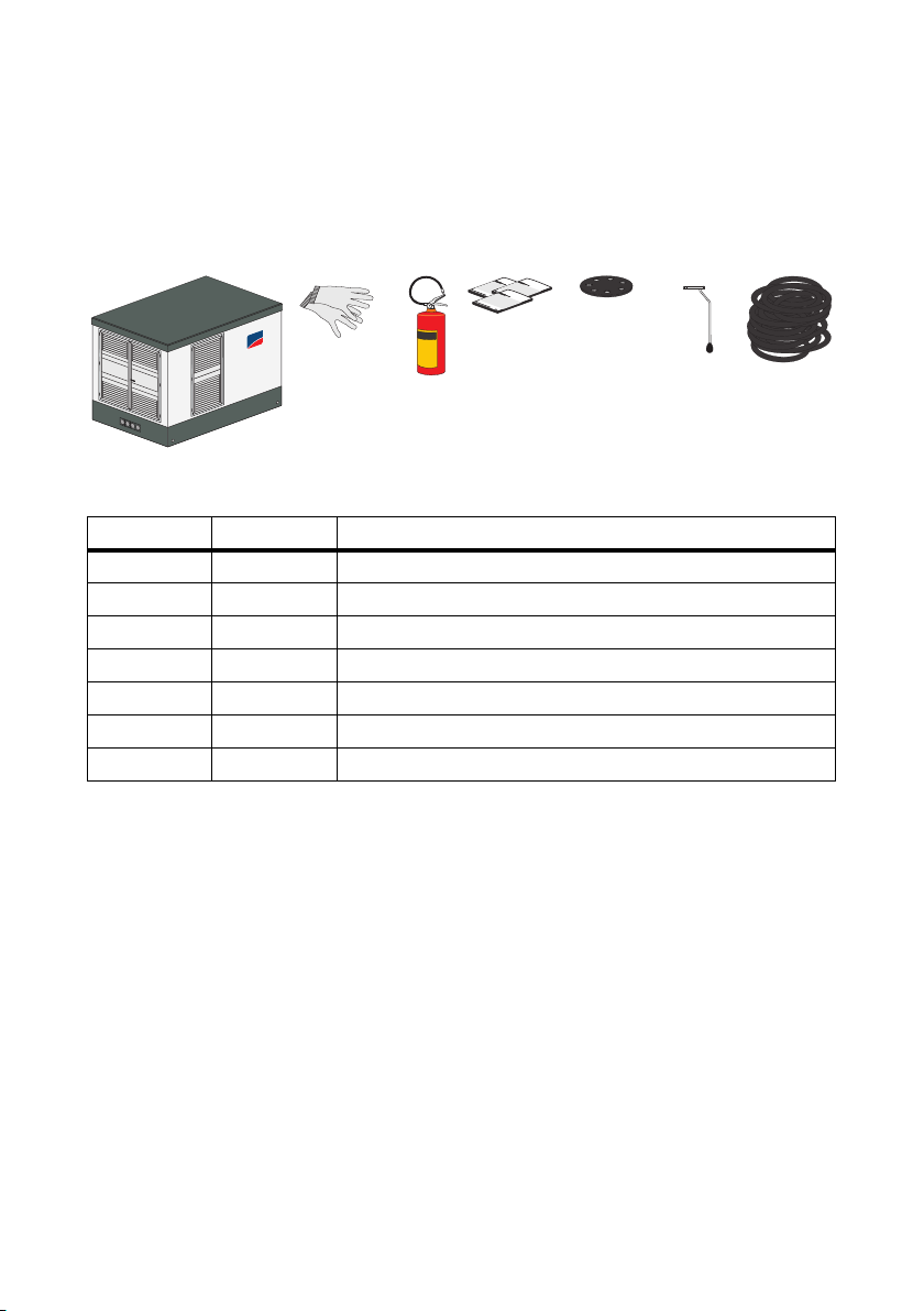
4Scope of Delivery
Check the delivery for completeness and any visible external damage. If the shipment is incomplete
or damaged, contact SMA Solar Technology AG.
Figure3: Scope of Delivery
Position Quantity Description
A 1 Transformer Compact Station
B1Gloves
C 1 Fire extinguisher
D 1 Installation manual, circuit diagram, documentation
E 6 Cable entries
F1Operating lever
G9/18
*
9 cables per inverter
**
Optional
*
ÖLFLEX® TRAFO cables
**
**
12 TCS-IT-IEN103610 Installation Manual
Page 13

SMA Solar Technology AG 5Installation Site
5 Installation Site
5.1 Choosing an Installation Site
Ambient conditions
• The installation site must be accessible at all times.
• The installation site must not be higher than 1 000 m above MSL.
• All minimum clearances must be maintained.
• A safety clearance of 5 000 mm must be maintained from flammable objects.
• All ambient conditions must be met (see section 9"Technical Data",page30).
Installation Manual TCS-IT-IEN103610 13
Page 14

5Installation Site SMA Solar Technology AG
8"3/*/(
Minimum clearances
Cable fire hazard.
Differing cable lengths lead to greater warming of the cables.
• All line conductors from the inverter to the Transformer Compact Station must be the same
length. However, the cables may not be longer than 15 m between termination points.
Figure4: Minimum clearances for the Transformer Compact Station
Position Description
AInverter
B Cabling between the inverter and the
Transformer Compact Station
C Transformer Compact Station
14 TCS-IT-IEN103610 Installation Manual
Page 15

SMA Solar Technology AG 6Transport and Installation
8"3/*/(
/05*$&
/05*$&
A
SMA
SMA
A
A
A
6 Transport and Installation
Crush hazard: The Transformer Compact Station may tip over if not transported
properly.
The Transformer Compact Station's center of gravity is not in the middle of the device.
• The means of transportation must be designed for a 17 t load.
• Do not tip the Transformer Compact Station during transportation.
• Transport the Transformer Compact Station as low to the ground as possible.
• Always use all lifting holes when transporting the device.
• Avoid sudden, jerky movements during transportation.
Transporting the device without transport locks on the medium-voltage transformer may
damage the medium-voltage transformer.
• Do not remove the transport locks on the medium-voltage transformer.
Moisture penetration may damage the Transformer Compact Station.
• Transport and store the Transformer Compact Station with its doors closed only.
Figure5: Lifting holes for lifting spreader on the front and back
Position Description
A Lifting holes for spreader
Installation Manual TCS-IT-IEN103610 15
Page 16

6Transport and Installation SMA Solar Technology AG
S
M
A
S
M
A
1. Attach the spreader chains to the lifting holes.
2. Slowly raise the spreader until the spreader chains
are taut.
3. Slowly lift the Transformer Compact Station.
4. Transport the Transformer Compact Station.
5. Set down the Transformer Compact Station in the
center of the foundation. Observe the foundation
boundaries.
6. Remove the spreader chains from the lifting holes.
16 TCS-IT-IEN103610 Installation Manual
Page 17

SMA Solar Technology AG 7Electrical Connection
7 Electrical Connection
7.1 Set up Electrical Connection
Procedure See
1 Run the cable from the low-voltage switchgear to the
inverter.
2 Run the cable for the inverter power supply and for
the connection to the transformer protection unit.
3 Insert the cable. Section 7.2.2
4 Connect the cable for the internal power supply to
the inverter.
5 Connect the protective conductor. Section 7.3.3
6 Connect the inverter to the output terminal of the
transformer protection unit in the station sub-
distribution board.
7 Connect the internal power supply cable to the
Transformer Compact Station.
8 Connect the cable for the low-voltage switchgear. Documentation for the low-voltage
9 Connect the cable for the medium-voltage
switchgear.
10 Close cable entries. Documentation for the cable entries.
Section 7.2.1
Section 7.3.2
Section 7.3.4
Section 7.3.5
switchgear.
Documentation for the medium-
voltage switchgear.
Installation Manual TCS-IT-IEN103610 17
Page 18

7Electrical Connection SMA Solar Technology AG
L2
L1
L3
L2
L1
L3
L2
L1
L3
1d
>2d
--
>2d
--
7.2 Laying cables
7.2.1 Running Cables between the Low-Voltage Switchgear and the Inverter
☐ The AC cables are 3-phase cables.
☐ Between the low-voltage switchgear and the inverter there are three separate cable runs for the
AC cables, e. g. cable channels.
☐ The spacing between the cable runs must be at least twice the diameter of an AC cable.
Figure6: Arrangement of AC cables with three cables per line conductor (example).
Maintain cable clearances
Run an L1, L2 and L3 line conductor in each cable run. The spacing between the cable pairs
must be at least twice the diameter of a cable. This prevents current imbalances.
• Run the cables as described.
18 TCS-IT-IEN103610 Installation Manual
Page 19

SMA Solar Technology AG 7Electrical Connection
A
B
L3
L2
L1
7.2.2 Inserting the Cables
Figure7: Position of cable entries
Position Description
A Cable entries for cables for the following devices or components:
• Low-voltage switchgear
• Internal power supply for the inverter
•Protective conductor
• Transformer protection
• If internal power is supplied by an external source: internal power supply for
the Transformer Compact Station
B Cable entries for the medium-voltage switchgear
• Insert the cables into the Transformer Compact
Station (see the cable entry manufacturer's
documentation on inserting the cables):
– The cables that connect the medium-voltage
switchgear to the point of common connection
– The cables that connect the low-voltage
switchgear to the inverters
– The cables for the inverters' internal power
supply
– The cables for the transformer protection unit
– If internal power is supplied by an external source: the cable for the internal power supply
of the Transformer Compact Station
Installation Manual TCS-IT-IEN103610 19
Page 20

7Electrical Connection SMA Solar Technology AG
7.3 Connecting Cables
7.3.1 Connection Area of the Station Sub-Distribution Board
Figure8: Connection area for the station sub-distribution board
Position Description
A Connection terminal clamps for internal power supply
B Connection terminals for the first Sunny Central
C Connection terminals for the second Sunny Central
*
D Connecting bar for the protective conductor
E Connection terminals for the transformer protection unit for the first Sunny Central
20 TCS-IT-IEN103610 Installation Manual
Page 21

SMA Solar Technology AG 7Electrical Connection
Position Description
F Connection terminals for the transformer protection unit for the second Sunny
*
Only for Transformer Compact Station 1000SC/1250SC/1600SC
Central
*
7.3.2 Connecting Cables for Inverter's Internal Power Supply
1. Connect the inverter's internal power supply.
– Strip cable jacket.
– Strip insulation off the wires.
–Connect the wires.
2. If you have two inverters: connect the internal power
supply for the second inverter.
– Strip cable jacket.
– Strip insulation off the wires.
–Connect the wires.
7.3.3 Connecting Protective Conductors
1. Strip the cable insulation.
2. Connect the cable.
Installation Manual TCS-IT-IEN103610 21
Page 22

7Electrical Connection SMA Solar Technology AG
7.3.4 Connecting Inverter to Output Terminal of Transformer Protection Unit in Station Sub-Distribution Board
1. Connect the transformer protection unit of the inverter.
Select the correct terminal.
Before connecting the wires, make sure you have selected the correct terminal.
– Strip cable jacket.
– Strip insulation off the wires.
–Connect the wires.
2. If you have two inverters: connect the transformer protection unit for the second inverter.
– Strip cable jacket.
– Strip insulation off the wires.
–Connect the wires.
22 TCS-IT-IEN103610 Installation Manual
Page 23

SMA Solar Technology AG 7Electrical Connection
7.3.5 Connecting Cables for the Internal Power Supply of the Transformer Compact Station
Depending on the options ordered, the Transformer Compact Station may contain an internal power
supply transformer. If it does not contain an internal power supply transformer, the internal power will
have to be supplied by an external source.
1. Strip cable jacket.
2. Strip insulation off the wires.
3. Connect the wires.
Installation Manual TCS-IT-IEN103610 23
Page 24

7Electrical Connection SMA Solar Technology AG
SMA
A
B
7.4 Set Voltage on Internal Power Supply Transformer
The output voltage of the internal power supply transformer must match the input voltage of the
inverter's internal power supply. To do this, adapt the primary and secondary sides of the internal
power supply transformer to the inverter.
Figure9: Position of connecting terminal plates
Position Description
A Connecting terminal plate on the secondary side
B Connecting terminal plate on the primary side
1. Set the input voltage on the primary side. This adjusts the output voltage to the inverter's input
voltage (see circuit diagram for the Transformer Compact Station).
2. Set the output voltage on the secondary side. This adjusts the output voltage to the inverter's
input voltage (see circuit diagram for the Transformer Compact Station).
24 TCS-IT-IEN103610 Installation Manual
Page 25

SMA Solar Technology AG 8Commissioning
8"3/*/(
8Commissioning
8.1 Commissioning the Transformer Compact Station
Danger of fire if the connection is faulty.
• Switch off all switch elements:
– Switch off the low-voltage switchgear (see the documentation for the low-voltage
switchgear).
– Switch off the medium-voltage switchgear (see the documentation for the medium-voltage
switchgear).
– Remove fuses.
– Open the miniature circuit-breaker.
– Open the residual current device.
Warranty and Guarantee Claims
Warranty or guarantee claims can only be made valid if the initial start-up was carried out by
SMA Solar Technology AG or if the fully completed and signed "Initial Commissioning Report
for Sunny Central Systems" is completed and available at SMA Solar Technology AG. The
commissioning report is included with Sunny Central.
Installation Manual TCS-IT-IEN103610 25
Page 26

8Commissioning SMA Solar Technology AG
AB C
DEFGHIKL
Figure10: Overview of station sub-distribution board:
Position Description Explanation
A Discharger Overvoltage Protection
B Main Circuit Breaker Miniature circuit-breaker for the entire Transformer
C Voltage supply SC1 Miniature circuit-breaker for the first inverter
D Voltage supply fan motor Miniature circuit-breaker for the fan
E Hermetical full protection &
F Communit voltage supply Miniature circuit-breaker for the Communit
G Reserve Reserve miniature circuit-breaker
HVoltage supply feed-in meter Miniature circuit-breaker for the GSE meter
I Voltage supply power outlet Miniature circuit-breaker with integrated RCD for outlet
K Voltage supply lighting Miniature circuit-breaker for station lighting
L Voltage supply SC2 Miniature circuit-breaker for the second inverter
26 TCS-IT-IEN103610 Installation Manual
Compact Station
Miniature circuit-breaker for the transformer protection
stop
unit
communication distribution box
with earth contact
Page 27

SMA Solar Technology AG 8Commissioning
Requirements
☐ The medium-voltage switchgear is switched off.
☐ The low-voltage switchgear is switched off.
☐ All terminals have been connected as per the instructions and the circuit diagram (see section
7"Electrical Connection",page17).
1. Inspect the cabling to the Transformer Compact Station (see section 8.2).
2. Make sure the temperature settings on the Hermetic transformer protection unit are correct:
– Warning temperature: 90°C
– Actuation temperature: 100°C
3.
Only a duly authorized person trained in electrical safety can connect the AC
voltage of the medium-voltage transformer.
Have the AC voltage of the medium-voltage transformer connected externally.
4.
Only a duly authorized person trained in electrical safety can switch on the
medium-voltage switchgear.
Have the medium-voltage switchgear switched on (see the documentation for the
medium-voltage switchgear).
5. Check the low AC voltage in the low-voltage switchgear (see section 8.3).
6. If you have an internal power supply transformer: Connect the internal power supply for the
Transformer Compact Station (see section 8.4).
7. Turn on the power supply to the Transformer Compact Station with the "main circuit breaker".
8. Turn on the station lighting with the "voltage supply lighting" miniature circuit-breaker.
9. Energize the earthed outlet with the "voltage supply power outlet" miniature circuit-breaker with
the integrated residual current device.
10. Turn on the fan with the "voltage supply fan motor" miniature circuit-breaker.
11. Turn on the GSE meter with the "voltage supply feed-in meter" miniature circuit-breaker.
12. Turn on Communit with the "voltage supply Communit" miniature circuit-breaker.
13. Turn on low-voltage switchgear (see the documentation for the low-voltage switchgear).
14. Connect the internal power supply for the inverter (see section 8.5).
15. Commission the inverter (see the inverter documentation).
Installation Manual TCS-IT-IEN103610 27
Page 28

8Commissioning SMA Solar Technology AG
L3
L2
L1
8.2 Inspecting Cabling to the Transformer Compact Station
1. Verify that all connections are connected as described in the circuit diagram.
2. Verify that all terminals are firmly in place.
3. Check the Transformer Compact Station's equipotential bonding to the installation site. Bond
them together if needed.
8.3 Examining Low AC Voltage in Low-Voltage Switchgear
1. Check the phase sequence of the low voltage. Correct if necessary.
2. Measure the low voltage difference between the line conductors and log it in the commissioning
report.
–L
- L
1
2
–L1 - L
3
–L2 - L
3
☑ The low voltage is within ± 5 V of the nominal voltage of the inverter.
✖ Does the low voltage vary from the nominal voltage of the inverter by more than ± 5 V?
• De-energize the medium-voltage transformer.
• Have a duly authorized person change the turns ratio of the medium-voltage transformer by
adjusting the on-load tap-changer.
☑ The on-load tap-changer will audibly click into place.
• Proceed to step 2.
8.4 Connecting the Internal Power Supply for the Transformer Compact Station
1. Insert the fuses in the fuse-switch-disconnector.
2. Close the fuse-switch-disconnector.
28 TCS-IT-IEN103610 Installation Manual
Page 29

SMA Solar Technology AG 8Commissioning
8.5 Connecting the Internal Power Supply for the Inverter
1. Close the "Voltage supply SC 1" miniature circuitbreaker for the first inverter.
2. If two inverters are used, in addition switch on "Voltage supply SC 2".
Installation Manual TCS-IT-IEN103610 29
Page 30

9Technical Data SMA Solar Technology AG
9 Technical Data
9.1 Transformer Compact Station 500SC
Medium-voltage side
Rated power (@ 25°C) P
AC nominal power (@ 45°C) P
AC nominal voltage V
AC voltage range V
Rated grid voltage V
Rated grid frequency f
Nominal current I
ACnom
AC
ACnom
AC
AC
AC
nom
15 kV / 20 kV
13.5 kV … 16.5 kV / 18 kV … 22 kV
Low-Voltage Side
Nominal input voltage V
Nominal input current I
AC
nom
Dimensions and Weight
Width x height x depth
with medium-voltage switchgear
Width x height x depth
without medium-voltage switchgear
Weight with medium-voltage switchgear 14.2 t
Weight without medium-voltage switchgear 9.8 t
Degree of protection
*
As per EN 60529
*
3 280 mm x 2 550 mm x 2 500 mm
2 380 mm x 2 550 mm x 2 500 mm
IP23
550 kVA
500 kVA
20 kV
50 Hz
14.5 A
270 V
1 070 A
Climatic Conditions
Operation temperature range − 20°C … +45°C
Relative humidity, non-condensing 15% … 95%
Maximum operating altitude above sea level
(MSL)
30 TCS-IT-IEN103610 Installation Manual
1 000 m
Page 31

SMA Solar Technology AG 9Technical Data
Options
Internal power supply transformer
Medium-voltage switchgear None / RE-T / C-C-T
Low-voltage switchgear 1 x LV/HRC switch-disconnector /
Pre-assembled cable set 5 m / 7.5 m / 10 m / 15 m
Communication distribution box Communit
Low-voltage meter GSE meter
*
Additional power classes available on request.
*
6kVA
1 x circuit breaker
9.2 Transformer Compact Station 630SC
Medium-voltage side
Rated power (@ 25°C) P
AC nominal power (@ 45°C) P
AC nominal voltage V
AC voltage range V
Rated grid voltage V
Rated grid frequency f
Nominal current I
ACnom
AC
ACnom
AC
AC
AC
nom
15 kV / 20 kV
13.5 kV … 16.5 kV / 18 kV … 22 kV
Low-Voltage Side
Nominal input voltage V
Nominal input current I
AC
nom
Dimensions and Weight
Width x height x depth
with medium-voltage switchgear
Width x height x depth
without medium-voltage switchgear
Weight with medium-voltage switchgear 14.5 t
Weight without medium-voltage switchgear 10.1 t
Degree of protection
*
As per EN 60529
*
3 280 mm x 2 550 mm x 2 500 mm
2 380 mm x 2 550 mm x 2 500 mm
IP23
700 kVA
630 kVA
20 kV
50 Hz
18.2 A
315 V
1 155 A
Installation Manual TCS-IT-IEN103610 31
Page 32

9Technical Data SMA Solar Technology AG
Climatic Conditions
Operation temperature range − 20°C … +45°C
Relative humidity, non-condensing 15% … 95%
Maximum operating altitude above sea level
1 000 m
(MSL)
Options
Internal power supply transformer
*
Medium-voltage switchgear None / RE-T / C-C-T
Low-voltage switchgear 1 x LV/HRC switch-disconnector /
Pre-assembled cable set 5 m / 7.5 m / 10 m / 15 m
Communication distribution box Communit
Low-voltage meter GSE meter
*
Additional power classes available on request.
6kVA
1 x circuit breaker
9.3 Transformer Compact Station 800SC
Medium-voltage side
Rated power (@ 25°C) P
AC nominal power (@ 45°C) P
AC nominal voltage V
AC voltage range V
Rated grid voltage V
Rated grid frequency f
Nominal current I
ACnom
AC
ACnom
AC
AC
AC
Nominal
13.5 kV … 16.5 kV / 18 kV … 22 kV
880 kVA
800 kVA
15 kV / 20 kV
20 kV
50 Hz
23.1 A
Low-Voltage Side
Nominal Voltage V
Nominal voltage reduced by 2.5%*
Nominal voltage reduced by 5.0%
Nominal voltage reduced by 7.5%* V
Nominal voltage reduced by 10.0%
Nominal voltage reduced by 12.5%* V
Nominal current I
*
Can be set with on-load tap-changer in transformer
32 TCS-IT-IEN103610 Installation Manual
AC
V
AC
*
V
AC
AC
*
V
AC
AC
nom
360 V
351 V
342 V
333 V
324 V
315 V
1 283 A
Page 33

SMA Solar Technology AG 9Technical Data
Dimensions and Weight
Width x height x depth
3 280 mm x 2 550 mm x 2 500 mm
with medium-voltage switchgear
Width x height x depth
2 380 mm x 2 550 mm x 2 500 mm
without medium-voltage switchgear
Weight with medium-voltage switchgear 15.0 t
Weight without medium-voltage switchgear 10.6 t
Degree of protection
*
As per EN 60529
*
IP23
Climatic Conditions
Operation temperature range − 20°C … +45°C
Relative humidity, non-condensing 15% … 95%
Maximum operating altitude above sea level
1 000 m
(MSL)
Options
Internal power supply transformer
*
Medium-voltage switchgear None / RE-T / C-C-T
Low-voltage switchgear 1 x LV/HRC switch-disconnector /
Pre-assembled cable set 5 m / 7.5 m / 10 m / 15 m
Communication distribution box Communit
Low-voltage meter GSE meter
*
Additional power classes available on request.
6kVA
1 x circuit breaker
9.4 Transformer Compact Station 1000SC
Medium-voltage side
Rated power (@ 25°C) P
AC nominal power (@ 45°C) P
AC nominal voltage V
AC voltage range V
Rated grid voltage V
Rated grid frequency f
Nominal current I
Installation Manual TCS-IT-IEN103610 33
ACnom
AC
ACnom
AC
AC
AC
nom
13.5 kV … 16.5 kV / 18 kV … 22 kV
1 100 kVA
1 000 kVA
15 kV / 20 kV
20 kV
50 Hz
28.9 A
Page 34

9Technical Data SMA Solar Technology AG
Low-Voltage Side
Nominal input voltage V
Nominal input current I
AC
nom
270 V
2x1070A
Dimensions and Weight
Width x height x depth
with medium-voltage switchgear
Width x height x depth
without medium-voltage switchgear
Weight with medium-voltage switchgear 16.3 t
Weight without medium-voltage switchgear 11.9 t
Degree of protection
*
As per EN 60529
*
3 280 mm x 2 550 mm x 2 500 mm
2 380 mm x 2 550 mm x 2 500 mm
IP23
Climatic Conditions
Operation temperature range − 20°C … +45°C
Relative humidity, non-condensing 15% … 95%
Maximum operating altitude above sea level
1 000 m
(MSL)
Options
Internal power supply transformer
*
Medium-voltage switchgear None / RE-T / C-C-T
Low-voltage switchgear 2 x LV/HRC switch-disconnectors /
Pre-assembled cable set 5 m / 7.5 m / 10 m / 15 m
Communication distribution box Communit
Low-voltage meter GSE meter
*
Additional power classes available on request.
6kVA
2 x circuit breakers
34 TCS-IT-IEN103610 Installation Manual
Page 35

SMA Solar Technology AG 9Technical Data
9.5 Transformer Compact Station 1250SC
Medium-voltage side
Rated power (@ 25°C) P
AC nominal power (@ 45°C) P
AC nominal voltage V
AC voltage range V
Rated grid voltage V
Rated grid frequency f
Nominal current I
ACnom
AC
ACnom
AC
AC
AC
nom
13.5 kV … 16.5 kV / 18 kV … 22 kV
1 375 kVA
1 250 kVA
15 kV / 20 kV
Low-Voltage Side
Nominal input voltage V
Nominal input current I
AC
nom
2x1155A
Dimensions and Weight
Width x height x depth
with medium-voltage switchgear
Width x height x depth
without medium-voltage switchgear
Weight with medium-voltage switchgear 16.8 t
Weight without medium-voltage switchgear 12.4 t
Degree of protection
*
As per EN 60529
*
3 280 mm x 2 550 mm x 2 500 mm
2 380 mm x 2 550 mm x 2 500 mm
IP23
20 kV
50 Hz
36.4 A
315 V
Climatic Conditions
Operation temperature range − 20°C … +45°C
Relative humidity, non-condensing 15% … 95%
Maximum operating altitude above sea level
(MSL)
Installation Manual TCS-IT-IEN103610 35
1 000 m
Page 36

9Technical Data SMA Solar Technology AG
Options
Internal power supply transformer
Medium-voltage switchgear None / RE-T / C-C-T
Low-voltage switchgear 2 x LV/HRC switch-disconnectors /
Pre-assembled cable set 5 m / 7.5 m / 10 m / 15 m
Communication distribution box Communit
Low-voltage meter GSE meter
*
Additional power classes available on request.
*
6kVA
2 x circuit breakers
9.6 Transformer Compact Station 1600SC
Medium-voltage side
Rated power (@ 25°C) P
AC nominal power (@ 45°C) P
AC nominal voltage V
AC voltage range V
Rated grid voltage V
Rated grid frequency f
Nominal current I
ACnom
AC
ACnom
AC
AC
AC
nom
Low-Voltage Side
Nominal input voltage V
Nominal voltage reduced by 2.5%
Nominal voltage reduced by 5.0%
Nominal voltage reduced by 7.5%* V
Nominal voltage reduced by 10.0%
Nominal voltage reduced by 12.5%*V
Nominal input current I
*
Can be set with an on-load tap-changer in the transformer
AC
*
V
AC
*
V
AC
AC
*
V
AC
AC
nom
1 760 kVA
1 600 kVA
15 kV / 20 kV
13.5 kV … 16.5 kV / 18 kV … 22 kV
20 kV
50 Hz
46.2 A
360 V
351 V
342 V
333 V
324 V
315 V
2x1283A
36 TCS-IT-IEN103610 Installation Manual
Page 37

SMA Solar Technology AG 9Technical Data
Dimensions and Weight
Width x height x depth
3 280 mm x 2 550 mm x 2 500 mm
with medium-voltage switchgear
Width x height x depth
2 380 mm x 2 550 mm x 2 500 mm
without medium-voltage switchgear
Weight with medium-voltage switchgear 17.4 t
Weight without medium-voltage switchgear 13.0 t
Degree of protection
*
As per EN 60529
*
IP23
Climatic Conditions
Operation temperature range − 20°C … +45°C
Relative humidity, non-condensing 15% … 95%
Maximum operating altitude above sea level
1 000 m
(MSL)
Options
Internal power supply transformer
*
Medium-voltage switchgear None / RE-T / C-C-T
Low-voltage switchgear 2 x LV/HRC switch-disconnectors /
Pre-assembled cable set 5 m / 7.5 m / 10 m / 15 m
Communication distribution box Communit
Low-voltage meter GSE meter
*
Additional power classes available on request.
6kVA
2 x circuit breakers
Installation Manual TCS-IT-IEN103610 37
Page 38

10Contact SMA Solar Technology AG
10 Contact
If you have technical problems concerning our products, contact the SMA Serviceline. We need the
following information in order to provide you with the necessary assistance:
• Serial number of the Transformer Compact Station
• Type designation of the Transformer Compact Station
• Installation site address
SMA Solar Technology AG
Sonnenallee 1
34266 Niestetal, Germany
www.SMA.de
SMA Serviceline
Tel. +49 561 9522 299
Fax +49 561 9522 3299
E‑Mail: SunnyCentral.Service@SMA.de
38 TCS-IT-IEN103610 Installation Manual
Page 39

SMA Solar Technology AG Legal Restrictions
The information contained in this document is the property of SMA Solar Technology AG. Publishing its content, either partially or
in full, requires the written permission of SMA Solar Technology AG. Any internal company copying of the document for the
purposes of evaluating the product or its correct implementation is allowed and does not require permission.
Exclusion of liability
The general terms and conditions of delivery of SMA Solar Technology AG shall apply.
The content of these documents is continually checked and amended, where necessary. However, discrepancies cannot be
excluded. No guarantee is made for the completeness of these documents. The latest version is available online at www.SMA.de
or from the usual sales channels.
Guarantee or liability claims for damages of any kind are excluded if they are caused by one or more of the following:
• Damages during transportation
• Improper or inappropriate use of the product
• Operating the product in an unintended environment
• Operating the product whilst ignoring relevant, statutory safety regulations in the deployment location
• Ignoring safety warnings and instructions contained in all documents relevant to the product
• Operating the product under incorrect safety or protection conditions
• Altering the product or supplied software without authority
• The product malfunctions due to operating attached or neighboring devices beyond statutory limit values
• In case of unforeseen calamity or force majeure
The use of supplied software produced by SMA Solar Technology AG is subject to the following conditions:
• SMA Solar Technology AG rejects any liability for direct or indirect damages arising from the use of software developed by
SMA Solar Technology AG. This also applies to the provision or non-provision of support activities.
• Supplied software not developed by SMA Solar Technology AG is subject to the respective licensing and liability agreements
of the manufacturer.
SMA Factory Warranty
The current guarantee conditions come enclosed with your device. These are also available online at www.SMA.de and can be
downloaded or are available on paper from the usual sales channels if required.
Trademarks
All trademarks are recognized even if these are not marked separately. Missing designations do not mean that a product or brand
is not a registered trademark.
The Bluetooth
Solar Technology AG is under license.
SMA Solar Technology AG
Sonnenallee 1
34266 Niestetal
Germany
Tel. +49 561 9522-0
Fax +49 561 9522-100
www.SMA.de
E-Mail: info@SMA.de
© 2004 to 2011SMA Solar Technology AG. All rights reserved
Installation Manual TCS-IT-IEN103610 39
®
wor d mark an d logos a re registe red trad emarks own ed by Blu etoo th SIG , Inc. an d any use of such mar ks by SMA
Page 40

XXX4."4PMBSDPN
4."4PMBS5FDIOPMPHZ
4."4PMBS5FDIOPMPHZ"(
XXX4."EF
4.""NFSJDB--$
XXX4.""NFSJDBDPN
4."5FDIOPMPHZ"VTUSBMJB1UZ-UE
XXX4.""VTUSBMJBDPNBV
4."#FOFMVY413-
XXX4."#FOFMVYDPN
4."#FJKJOH$PNNFSDJBM$P-UE
XXX4."$IJOBDPN
4."$[FDI3FQVCMJDTSP
XXX4."$[FDIDPN
4."'SBODF4"4
XXX4."'SBODFDPN
4.")FMMBT"&
XXX4.")FMMBTDPN
4."*C©SJDB5FDOPMPHB4PMBS4-
XXX4."*CFSJDBDPN
4."*UBMJB4SM
XXX4."*UBMJBDPN
4."5FDIOPMPHZ,PSFB$P-UE
XXX4.",PSFBDPN
 Loading...