

Page 1
EN
Monitoring and Visualisation of Plant Data
Sunny WebBox, Sunny WebBox with Bluetooth
SMA Cluster Controller in Sunny Portal
User Manual
®
and
SPortal-WB-CLCON-BA-en-25 | Version 2.5
Page 2

Page 3

SMA Solar Technology AG Table of Contents
Table of Contents
1 Information on this Document. . . . . . . . . . . . . . . . . . . . . . . 6
2 Sunny Portal . . . . . . . . . . . . . . . . . . . . . . . . . . . . . . . . . . . . . 8
2.1 Intended Use. . . . . . . . . . . . . . . . . . . . . . . . . . . . . . . . . . . . . . . . 8
2.2 System Requirements . . . . . . . . . . . . . . . . . . . . . . . . . . . . . . . . . 8
3 Getting Started . . . . . . . . . . . . . . . . . . . . . . . . . . . . . . . . . . . 9
3.1 Registering the Plant in Sunny Portal. . . . . . . . . . . . . . . . . . . . . . 9
3.2 Logging In and Out of Sunny Portal . . . . . . . . . . . . . . . . . . . . . 10
3.3 Next Steps . . . . . . . . . . . . . . . . . . . . . . . . . . . . . . . . . . . . . . . . 11
4 Menu Overview . . . . . . . . . . . . . . . . . . . . . . . . . . . . . . . . . 12
5 Page, Table and Diagram Functions . . . . . . . . . . . . . . . . 16
6 Page Design . . . . . . . . . . . . . . . . . . . . . . . . . . . . . . . . . . . . 18
6.1 Standard Pages . . . . . . . . . . . . . . . . . . . . . . . . . . . . . . . . . . . . 18
6.1.1 Overview of Standard Pages . . . . . . . . . . . . . . . . . . . . . . . . . . . . . . . . . . . . 18
6.1.2 Creating Standard Pages . . . . . . . . . . . . . . . . . . . . . . . . . . . . . . . . . . . . . . . 19
6.2 Creating a New Customized Page. . . . . . . . . . . . . . . . . . . . . . 20
6.3 Generating Page Content. . . . . . . . . . . . . . . . . . . . . . . . . . . . . 21
6.3.1 Overview of Page Content . . . . . . . . . . . . . . . . . . . . . . . . . . . . . . . . . . . . . . 21
6.3.2 Creating Tables. . . . . . . . . . . . . . . . . . . . . . . . . . . . . . . . . . . . . . . . . . . . . . . 25
6.3.3 Adding a Plant Profile . . . . . . . . . . . . . . . . . . . . . . . . . . . . . . . . . . . . . . . . . . 27
6.3.4 Creating an XY Diagram. . . . . . . . . . . . . . . . . . . . . . . . . . . . . . . . . . . . . . . . 27
6.3.5 Creating a Diagram . . . . . . . . . . . . . . . . . . . . . . . . . . . . . . . . . . . . . . . . . . . 29
6.3.6 Creating a Slide Show . . . . . . . . . . . . . . . . . . . . . . . . . . . . . . . . . . . . . . . . . 31
6.3.7 Creating an Image . . . . . . . . . . . . . . . . . . . . . . . . . . . . . . . . . . . . . . . . . . . . 32
6.3.8 Creating Plant Monitoring. . . . . . . . . . . . . . . . . . . . . . . . . . . . . . . . . . . . . . . 33
6.3.9 Creating an Overview. . . . . . . . . . . . . . . . . . . . . . . . . . . . . . . . . . . . . . . . . . 34
6.3.10 Creating Text. . . . . . . . . . . . . . . . . . . . . . . . . . . . . . . . . . . . . . . . . . . . . . . . . 34
6.4 Changing/Deleting Page Contents. . . . . . . . . . . . . . . . . . . . . . 35
User Manual SPortal-WB-CLCON-BA-en-25 3
Page 4

Table of Contents SMA Solar Technology AG
6.5 Changing the Page Name . . . . . . . . . . . . . . . . . . . . . . . . . . . . 35
6.6 Publishing Pages . . . . . . . . . . . . . . . . . . . . . . . . . . . . . . . . . . . . 35
6.7 Deleting Pages . . . . . . . . . . . . . . . . . . . . . . . . . . . . . . . . . . . . . 36
6.8 Changing Page Arrangement in the Visualization Menu . . . . . 37
6.8.1 Creating a New Group. . . . . . . . . . . . . . . . . . . . . . . . . . . . . . . . . . . . . . . . . 37
6.8.2 Changing the Positions of Pages and Groups. . . . . . . . . . . . . . . . . . . . . . . . 37
6.8.3 Deleting a Group . . . . . . . . . . . . . . . . . . . . . . . . . . . . . . . . . . . . . . . . . . . . . 37
7 System Monitoring. . . . . . . . . . . . . . . . . . . . . . . . . . . . . . . 38
7.1 Overview of Monitoring Functions . . . . . . . . . . . . . . . . . . . . . . 38
7.2 System Logbook . . . . . . . . . . . . . . . . . . . . . . . . . . . . . . . . . . . . 39
7.2.1 Calling up and Filtering Messages . . . . . . . . . . . . . . . . . . . . . . . . . . . . . . . . 39
7.2.2 Acknowledging Messages . . . . . . . . . . . . . . . . . . . . . . . . . . . . . . . . . . . . . . 39
7.3 Plant Monitoring . . . . . . . . . . . . . . . . . . . . . . . . . . . . . . . . . . . . 40
7.3.1 Overview of Plant Monitoring. . . . . . . . . . . . . . . . . . . . . . . . . . . . . . . . . . . . 40
7.3.2 Setting Communication Monitoring. . . . . . . . . . . . . . . . . . . . . . . . . . . . . . . . 44
7.3.3 Setting Inverter Comparison . . . . . . . . . . . . . . . . . . . . . . . . . . . . . . . . . . . . . 45
7.3.4 Setpoint Monitoring: Setting the E-Mail Alert . . . . . . . . . . . . . . . . . . . . . . . . 45
7.4 Report Configuration. . . . . . . . . . . . . . . . . . . . . . . . . . . . . . . . . 46
7.4.1 Configuring the Daily Info Report/Monthly Info Report . . . . . . . . . . . . . . . . 47
7.4.2 Configuring an Event Report . . . . . . . . . . . . . . . . . . . . . . . . . . . . . . . . . . . . . 48
7.4.3 Manually Regenerating Reports . . . . . . . . . . . . . . . . . . . . . . . . . . . . . . . . . . 48
8 Plant Properties . . . . . . . . . . . . . . . . . . . . . . . . . . . . . . . . . 49
8.1 Plant Data . . . . . . . . . . . . . . . . . . . . . . . . . . . . . . . . . . . . . . . . . 49
8.1.1 Changing General Plant Data . . . . . . . . . . . . . . . . . . . . . . . . . . . . . . . . . . . 49
8.1.2 Changing the Plant Name. . . . . . . . . . . . . . . . . . . . . . . . . . . . . . . . . . . . . . . 50
8.1.3 Deleting the Plant . . . . . . . . . . . . . . . . . . . . . . . . . . . . . . . . . . . . . . . . . . . . . 50
8.1.4 Setting the Plant Power . . . . . . . . . . . . . . . . . . . . . . . . . . . . . . . . . . . . . . . . . 50
8.1.5 Changing the Plant Description. . . . . . . . . . . . . . . . . . . . . . . . . . . . . . . . . . . 51
8.1.6 Changing/Deleting the Plant Image . . . . . . . . . . . . . . . . . . . . . . . . . . . . . . . 51
8.2 Changing Operator Data . . . . . . . . . . . . . . . . . . . . . . . . . . . . . 52
4 SPortal-WB-CLCON-BA-en-25 User Manual
Page 5

SMA Solar Technology AG Table of Contents
8.3 Parameters . . . . . . . . . . . . . . . . . . . . . . . . . . . . . . . . . . . . . . . . 53
8.3.1 Changing the Feed-in Tariff . . . . . . . . . . . . . . . . . . . . . . . . . . . . . . . . . . . . . . 53
8.3.2 Changing the CO
8.3.3 Entering the Predicted Annual Yield. . . . . . . . . . . . . . . . . . . . . . . . . . . . . . . 54
8.3.4 Changing the Performance Ratio . . . . . . . . . . . . . . . . . . . . . . . . . . . . . . . . . 55
Avoided Factor . . . . . . . . . . . . . . . . . . . . . . . . . . . . . . . 53
2
9 Publishing Sunny Portal Pages . . . . . . . . . . . . . . . . . . . . . 57
10 Device Settings . . . . . . . . . . . . . . . . . . . . . . . . . . . . . . . . . . 58
10.1 Calling Up and Filtering the Device Overview . . . . . . . . . . . . . 58
10.2 Calling Up Device Properties . . . . . . . . . . . . . . . . . . . . . . . . . . 59
10.2.1 Activating/Deactivating the Device. . . . . . . . . . . . . . . . . . . . . . . . . . . . . . . . 63
10.2.2 Changing the Device Name . . . . . . . . . . . . . . . . . . . . . . . . . . . . . . . . . . . . . 64
10.2.3 Changing the Device Description . . . . . . . . . . . . . . . . . . . . . . . . . . . . . . . . . 64
10.2.4 Setting the Phase. . . . . . . . . . . . . . . . . . . . . . . . . . . . . . . . . . . . . . . . . . . . . . 64
10.2.5 Setting the Generator Capacity . . . . . . . . . . . . . . . . . . . . . . . . . . . . . . . . . . 65
10.2.6 Deleting a Device . . . . . . . . . . . . . . . . . . . . . . . . . . . . . . . . . . . . . . . . . . . . . 67
10.2.7 Adding/Replacing Devices (Configuration Wizard). . . . . . . . . . . . . . . . . . . 67
10.3 Calling up the Parameters of a Device . . . . . . . . . . . . . . . . . . . 68
11 User Management . . . . . . . . . . . . . . . . . . . . . . . . . . . . . . . 69
11.1 User Concept with Roles and Privileges . . . . . . . . . . . . . . . . . . 69
11.2 Creating a New User . . . . . . . . . . . . . . . . . . . . . . . . . . . . . . . . 70
11.3 Changing User Privileges . . . . . . . . . . . . . . . . . . . . . . . . . . . . . 70
11.4 Changing User Information. . . . . . . . . . . . . . . . . . . . . . . . . . . . 70
11.5 Deleting a User. . . . . . . . . . . . . . . . . . . . . . . . . . . . . . . . . . . . . 71
11.6 Changing your Password . . . . . . . . . . . . . . . . . . . . . . . . . . . . . 71
12 Troubleshooting . . . . . . . . . . . . . . . . . . . . . . . . . . . . . . . . . 72
13 Glossary . . . . . . . . . . . . . . . . . . . . . . . . . . . . . . . . . . . . . . . 73
14 Contact . . . . . . . . . . . . . . . . . . . . . . . . . . . . . . . . . . . . . . . . 75
User Manual SPortal-WB-CLCON-BA-en-25 5
Page 6
1 Information on this Document SMA Solar Technology AG
1 Information on this Document
Validity
This document is valid for plants in the Internet portal Sunny Portal, in which one of the following
communication products is installed:
•Sunny WebBox
•Sunny WebBox with Bluetooth
• SMA Cluster Controller
• Sunny Boy Control / Plus
•Sunny Data Control
Target Group
This document is intended for end users.
Additional Information
Links to additional information can be found at www.SMA-Solar.com:
Document title Document type
Performance Ratio Technical information
Symbols
Symbol Explanation
®
Wireless Technology
Information that is important for a specific topic or goal, but is not
safety-relevant
☑ Desired result
Typography
Typography Usage Example
"light" • Display messages on the
inverter
• Elements on a software
interface
•Connections
bold • Elements to be selected
• Elements to be entered
> • Several elements that are
to be selected
[Button/Key] • Button or key to be
selected or pressed
6 SPortal-WB-CLCON-BA-en-25 User Manual
• The value can be read off
in the "Energy" field.
•Select Settings.
•Enter 10 in the "minutes"
field.
•Select Settings > Date.
• Select [Next].
Page 7
SMA Solar Technology AG 1 Information on this Document
Nomenclature
Full designation Designation in this document
Small wind turbine system Plant
PV plant Plant
SMA Cluster Controller Cluster Controller
Sunny WebBox with Bluetooth
Wireless
Sunny WebBox with Bluetooth
®
Technology
Abbreviations
Abbreviation Designation Explanation
CSV Comma-Separated Values File format
IP Internet Protocol
PE Protective Earth Protective conductor
SSL Secure Sockets Layer Protocol for transmitting coded data via
the internet
URL Uniform Resource Locator
User Manual SPortal-WB-CLCON-BA-en-25 7
Page 8

2 Sunny Portal SMA Solar Technology AG
2 Sunny Portal
2.1 Intended Use
Sunny Portal is an Internet portal for the monitoring of plants as well as the visualization and
presentation of plant data.
In order to use Sunny Portal, you need an SMA product that can record your plant data and send
it to Sunny Portal (see Section 2.2 ”System Requirements” (page8)). Depending on which
SMA product sends the data to Sunny Portal, various functions are available in Sunny Portal.
2.2 System Requirements
☐ A computer with Internet access must be available.
☐ An Internet browser must be installed on the computer.
☐ JavaScript must be activated in the Internet browser.
SMA products required:
In order to use Sunny Portal you will need an SMA product that can record your plant data and send
it to Sunny Portal.
The following SMA products are capable of sending data to the Sunny Portal
•Sunny WebBox / Sunny WebBox with Bluetooth
• SMA Cluster Controller
• Sunny Boy Control / Plus
•Sunny Data Control
• Additional devices (not dealt with in this manual):
–Sunny Home Manager*
– Inverters with Webconnect function*
– Sunny Multigate for plants with module inverters*
* For information on these devices in Sunny Portal, see the user manual of the respective device in Sunny Portal.
®
Wireless Technology
Supported Internet browsers:
• Google Chrome as of version 14.0
• Microsoft Internet Explorer as of version 8
• Mozilla Firefox as of version 5
• Opera as of version 11.0
• Safari as of version 5.0
Recommended screen resolution:
• At least 1,024 x 768 pixels
8 SPortal-WB-CLCON-BA-en-25 User Manual
Page 9

SMA Solar Technology AG 3 Getting Started
3 Getting Started
3.1 Registering the Plant in Sunny Portal
You can register your plant via the following SMA products in Sunny Portal:
Sunny WebBox / Sunny WebBox with Bluetooth
• Register the Sunny WebBox in Sunny Portal as described in the Sunny WebBox /
Sunny WebBox with Bluetooth manuals.
SMA Cluster Controller:
• Register the Cluster Controller in Sunny Portal according to the instructions in the user manual
of the Cluster Controller.
Sunny Boy Control / Plus:
• If your Sunny Boy Control or Sunny Boy Control Plus is equipped with the optional
NET Piggy-Back, you can send the plant data to Sunny Portal directly via Ethernet or by
means of one of the available modems. Set the type of data transfer to Sunny Portal in the
Sunny Boy Control or Sunny Boy Control Plus according to the instructions in the
NET Piggy-Back manual.
• If your Sunny Boy Control or Sunny Boy Control Plus is not equipped with the optional
NET Piggy-Back, you can register your plant via Sunny Data Control.
Sunny Data Control:
• I n Su nny Dat a Co ntrol , confi gur e th e Su nny Po rta l e- mai l as des cri bed in the Sun ny D ata Con tro l
help. You can obtain the Sunny Data Control software from the download area at
www.SMA-Solar.com.
®
Wireless Technology:
User Manual SPortal-WB-CLCON-BA-en-25 9
Page 10
3 Getting Started SMA Solar Technology AG
3.2 Logging In and Out of Sunny Portal
Logging into Sunny Portal
Requirement:
☐ You have already registered your plant in Sunny Portal (see Section 3.1 ”Registering the Plant
in Sunny Portal” (page9)).
1. Open www.SunnyPortal.com.
2. Activate "SSL" for secure transmission of your login details.
3. In the "E-mail" field, enter the e-mail address you provided when you registered.
4. Enter the password you received by e-mail in the "Password" field.
5. Check the "Remain logged in" box to stay logged in. This way, y ou wil l not hav e to sign in aga in
for your next Sunny Portal session. You will stay logged in, even after closing your browser or
switching off your computer. The function will stay activated until you log out of Sunny Portal via
the lock symbol in the upper right corner.
Public or Shared Computers
If you are using a public computer or your computer is shared with other persons, please
deactivate the function "Remain logged in". Otherwise, other persons could access your
data in Sunny Portal.
6. Select [Login].
☑ Upon initial login, the "User Information" page opens.
7. Fill in address details.
8. Select [Save].
Delay in visualization
Sometimes it may take up to three hours before the data of your PV plant is displayed in
Sunny Portal.
Display depends on the transmitted plant data
Depending on the volume of the plant data transmitted, the display of the available data
on the pages may vary.
Logging Out of Sunny Portal
• To end your session in Sunny Portal, select "User Info/Logout > Logout" or log out via the lock
symbol in the top right-hand corner.
10 SPortal-WB-CLCON-BA-en-25 User Manual
Page 11

SMA Solar Technology AG 3 Getting Started
3.3 Next Steps
• Change your password to ensure that your Sunny Portal account i s pr ote cte d fr om u nau tho ris ed
access (see Section 11.6 ”Changing your Password” (page71)).
• Get acquainted with Sunny Portal (see Section 4 ”Menu Overview” (page12)).
• Design your own pages entirely according to your wishes (see Section 6 ”Page Design”
(page18)).
• Use the report function of Sunny Portal to receive current updates about your PV plant by e-mail
or text message (see Section 7.4 ”Report Configuration” (page46)).
• Enter the properties of your plant (see Section 8 ”Plant Properties” (page49)).
• Give friends access to your Sunny Portal as guests, standard users, installers, or administrators
(see Section 11 ”User Management” (page69)).
User Manual SPortal-WB-CLCON-BA-en-25 11
Page 12
4 Menu Overview SMA Solar Technology AG
4 Menu Overview
Menu Meaning
Plant Selection This menu will only be shown if more t han one p lant is a ssigned to you r
e-mail address. You can select the desired plant in this menu. The name
of the currently selected plant will be used for the main menu item
under the "Plant selection" main menu. All other pages always refer to
the currently selected plant.
Plant Selection
> Plant List
"Name of your plant" The menu includes pages with the most important information about
"Name of your plant"
> Plant profile
"Name of your plant"
> Energy and Power
The page includes an overview of the plants assigned to your e-mail
address. The following data is listed for each plant:
• Plant power in kWp
• Total yield so far
• Total yield for the following periods:
– current day
–previous day
–current month
• Specific plant yield (kWh/kWp) for the following periods:
–current month
–current year
When accessing the page, the plant list is always sorted in ascending
order according to the specific plant yield. Click on a blue value in the
header to sort the plant list in ascending order according to this value,
click again to sort the list in descending order.
your plant: key data, yield, monitoring, and messages. Sunny Portal
automatically creates the pages in this menu.
This page includes an overview with information for the active plant.
Sunny Portal compiles the plant profile from information that you have
entered on your Sunny Portal pages. Information that you have not
entered (e.g., "Operator") will not be shown in the plant profile. For
information in the plant profile (see Table ”Information in the Plant
Profile” (page15)).
This page shows the following data of the active plant in 4 diagrams:
• Day: power produced over the day
• Month: total yield per month in days
• Year: total yield per year in months
• Total: total yields per year
12 SPortal-WB-CLCON-BA-en-25 User Manual
Page 13
SMA Solar Technology AG 4 Menu Overview
Menu Meaning
"Name of your plant"
> Grid Management
This page will only be shown if in the plant a device is registered which
provides data on grid management (Cluster Controller or Power
Reducer Box). In the respective device, the use of Sunny Portal must be
activated and the settings for grid management carried out.
The page displays the following data:
• Diagrams with plant power and the specifications for active
power limitation stipulated by the network operator
• Table with reports from the plant logbook which are relevant for
gr id m ana gem ent . Ti p: C han ge t o th e pl ant log book by sel ect ing
"System Logbook".
• Diagrams with "active power limitation", "cos phi setpoint" and/
or "reactive power setpoint" by the network operator. Which
diagrams are shown depends on the operating mode of the
Cluster Controller/Power Reducer Box. In the case of a Power
Reducer Box, the different specifications for individual phases
can be represented by separate lines (L1, L2, L3).
"Name of your plant"
> Energy Balance
This page is only displayed in plants with a Meter Connection Box.
The page displays the following data in a diagram depending on the
type of meter connected:
•Plant power
• Purchased electricity
• Self-consumption
"Name of your plant"
> Sensors
This page is only shown if a Cluster Controller with connected sensors
is registered in the plant.
Depending on which sensors are connected, the page will show the
following data in diagrams:
• Irradiation
• Outside temperature and/or module temperature
Tip: If you disconnect the sensors from the Cluster Controller, the
data collected so far will remain visible.
"Name of your plant"
> Performance Ratio
This page is only shown if a Cluster Controller with connected
irradiation sensor is registered in the plant.
The page shows the following data in diagrams:
• Daily performance ratio and irradiation values for the current
month
• Monthly performance ratio values for the current year
"Name of your plant"
> Annual Comparison
The page shows the total yield and the specific yield of the active plant
per month in a yearly overview.
User Manual SPortal-WB-CLCON-BA-en-25 13
Page 14
4 Menu Overview SMA Solar Technology AG
Menu Meaning
"Name of your plant"
> Plant Monitoring
On this page, the following functions for monitoring the active pl ant are
available:
• Monitoring of communication between Sunny Portal and your
plant
• Monitoring of the plant by inverter comparison
• Monitoring of the grid operator specifications for your plant
(only for plants with a Cluster Controller or Power Reducer Box)
Plant monitoring, see Section 7.3 ”Plant Monitoring” (page40).
"Name of your plant"
> System Logbook
This page shows messages from Sunny Portal and the active plant.
These messages will help you to identify plant failures, for example.
The figure after the colon shows the number of unread warning,
disturbance and error messages.
Presentation This menu includes standard pages with visualizations of your plant
data that are created automatically by Sunny Portal (standard pages,
see Section 6.8 ”Changing Page Arrangement in the Visualization
Menu” (page37)). All pages that you create yourself are also stored
here by Sunny Portal (creating pages, see Section 6.2 ”Creating a
New Customized Page” (page20)).
Configuration This menu includes pages by means of which you can set different
co nfi gur ati ons for you r Su nny Por tal , e. g., cre ate own pag es, edit plant
properties, and create new pages.
• Visualization, see Section 6 ”Page Design” (page18)
• Plant properties, see Section 8 ”Plant Properties” (page49)
• Plant presentation, see Section 9 ”Publishing Sunny Portal
Pages” (page57)
• Device overview, see Section 10.1 ”Calling Up and Filtering the
Device Overview” (page58)
• Report configuration, see Section 7.4 ”Report Configuration”
(page46)
• User management, see Section 11 ”User Management”
(page69)
"User Info/Logout" This menu enables you to call up user information and end your Sunny
Portal session. On the "User Information" page, you can also change
your password.
• User information, see Section 11.4 ”Changing User Information”
(page70)
• Logout
14 SPortal-WB-CLCON-BA-en-25 User Manual
Page 15
SMA Solar Technology AG 4 Menu Overview
Information in the Plant Profile
The following table includes the information which may be found in the plant profile and the sources
for changing or entering such information.
Information in the Plant Profile Source
Location Section 8.1.1 ”Changing General Plant Data” (page49):
from details of city and country
Operator Section 8.2 ”Changing Operator Data” (page52)
Commissioning Section 8.1.1 ”Changing General Plant Data” (page49)
Plant power Section 8.1.4 ”Setting the Plant Power” (page50)
Annual production Section 8.3.3 ”Entering the Predicted Annual Yield”
CO
savings
2
(page54)
Modules Section 8.1.4 ”Setting the Plant Power” (page50)
Tilt angle Section 10.2.5 ”Setting the Generator Capacity”
Tracking
(page65), paragraph ”Configuring the power of an
inverter via multiple strings” (page65)
Inverter Sunny Portal receives this information from the devices
Communication
Description Section 8.1.5 ”Changing the Plant Description”
(page51)
Plant image next to the data Section 8.1.6 ”Changing/Deleting the Plant Image”
(page51)
User Manual SPortal-WB-CLCON-BA-en-25 15
Page 16
5 Page, Table and Diagram Functions SMA Solar Technology AG
5 Page, Table and Diagram Functions
Page Functions:
At the end of each page with at least two tables or diagrams, you can change the end date for all
diagrams and tables on the page. If the period presented in the table or the diagram is one year or
one month, the year or month of the entered end date will be adopted.
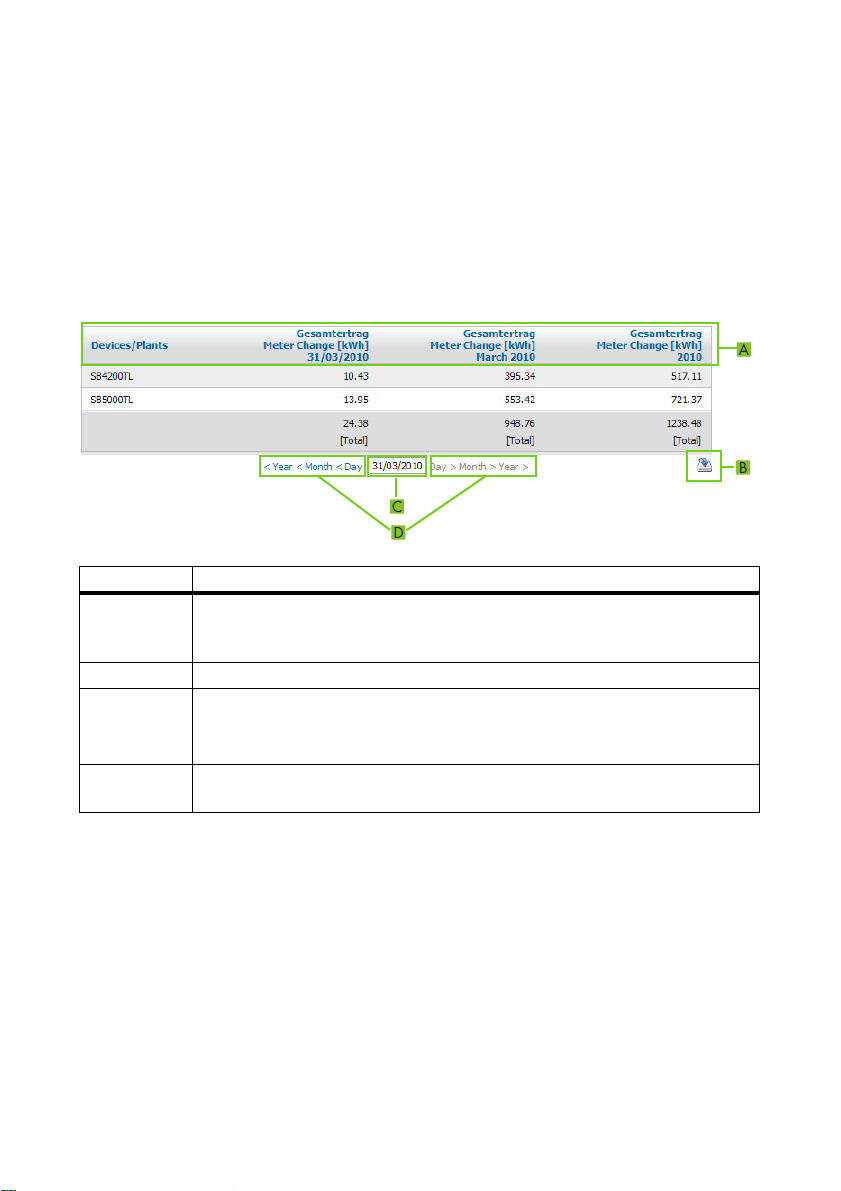
Table Functions:
Refer to the following sample table for a description of the functions.
Item Meaning
A The table header lets you sort the displayed data in ascending or de sce ndi ng order.
Click on a blue value in the header to sort the data in the table in ascending order,
click again to sort the data in descending order.
B Opens a window for saving the data in the configured format
C Opens calendar
In the calendar, you can use the arrows to scroll through the months and select the
desired display period.
D Here, you can scroll to the next or previous display period within the displayed
intervals.
16 SPortal-WB-CLCON-BA-en-25 User Manual
Page 17
SMA Solar Technology AG 5 Page, Table and Diagram Functions
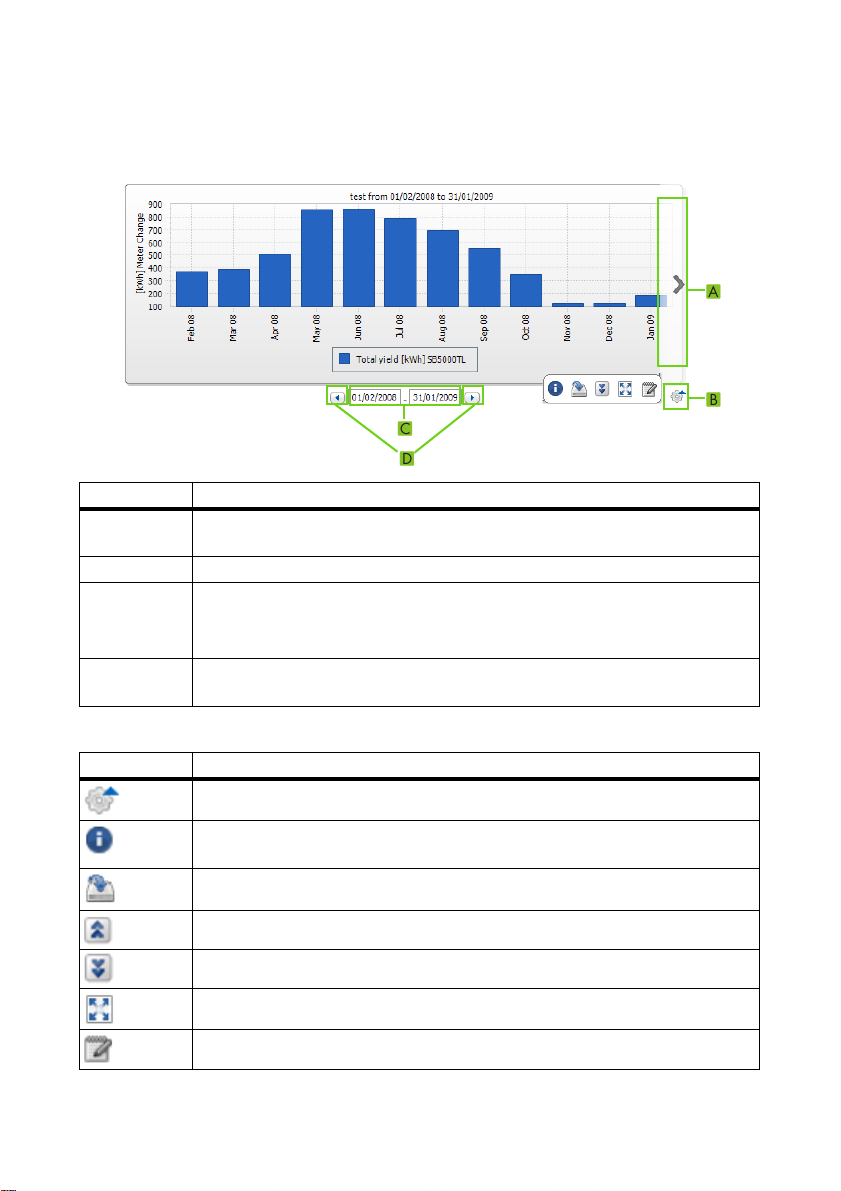
Diagram Functions:
Refer to the following sample table for a description of the functions.
Item Meaning
A Via the right and left margin of the diagram you can scroll to the next or previous
display period, providing that data is available.
B Opens more buttons for editing the diagram.
C Opens calendar
In the calendar, you can use the arrows to scroll through the months and select the
desired display period.
D Here, you can scroll to the next or previous display period within the displayed
intervals.
Buttons for Editing the Diagrams:
Symbol Meaning
Opens a sub-menu with the options described below for the diagram.
Opens a window with a tabular view of diagram values. If the window does not
open, refer to Section 12 ”Troubleshooting” (page72).
Opens a window for saving the data in the configured format
Shows legend
Hides legend
Shows full-screen diagram
Opens page configuration for editing the diagram.
User Manual SPortal-WB-CLCON-BA-en-25 17
Page 18
6 Page Design SMA Solar Technology AG
6 Page Design
6.1 Standard Pages
6.1.1 Overview of Standard Pages
Standard pages are pages with the most important data. They are created automatically by
Sunny Portal when your plant data is initially transmitted. The standard pages are saved in the
"Visualization" menu. Which standard pages are available for selection depends on the registered
device types. Standard pages can be modified (see Section 6.4 ”Changing/Deleting Page Contents”
(page35)). They can be recreated if they are erased or modified (see Section 6.1.2 ”Creating
Standard Pages” (page19)).
Standard Page Description
Plant overview Displayed data of the entire plant:
•CO
• Meter change of total yield per year in months
• Meter change of total yield and mean power values over
Power and energy Displayed data of the entire plant:
• Mean power value over one day in hours
• Meter change of total yield over seven days in days
Specific plant yield Displayed data of the entire plant:
• Mean values for specific plant yield over one month in days
• Mean values for specific plant yield over one year in months
Performance ratio This will be created and configured automatically in the following
cases:
• A Sunny SensorBox is added to your Sunny Portal plant.
• A communication device (with the exception of Cluster
Displayed data of the entire plant:
• Mean values for performance ratio over one month in days
• Mean values for performance ratio over one year in months
Devices
> Overview "Name Of
Inverter"
Displayed data of the inverter:
• Meter change of total yield over one year in months
• Mean power value over one day in hours
avoided and energy generated on the current day
2
two days in hours
Controller) sends data from an irradiation and temperature
sensor to Sunny Portal
Cluster Controller, the page "Performance Ratio" is
displayed in the "Name of your plant" menu.
*
. Tip: In the case of plants with
18 SPortal-WB-CLCON-BA-en-25 User Manual
Page 19
SMA Solar Technology AG 6 Page Design
Standard Page Description
Report
> Daily Plant Report
Displayed data:
• Meter change of total yield for the current day, current
month and current year
• Meter change of total yield for one day in hours
Report
> Monthly Plant Report
Displayed data:
• Meter change of total yield for current month and current
year
• Meter change of total yield for one month in days
Sensors
> "Name of the Sensor"
This will be created and configured automatically in the following
cases:
• A Sunny SensorBox is added to your Sunny Portal plant.
• A communication device (with the exception of Cluster
Controller) sends data from an irradiation and temperature
sensor to Sunny Portal
*
. Tip: In the case of plants with
Cluster Controller, the page "Sensors" is displayed in the
"Name of your plant" menu.
*The sensor will need to be adjusted manually in this case (see Section 8.3.4 ”Changing the Performance Ratio” (page55)).
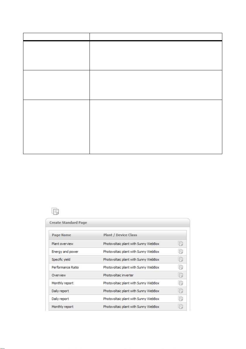
6.1.2 Creating Standard Pages
Sunny Portal creates the standard pages automatically. Should you have accidentally deleted or
changed a standard page, you can create the standard pages as described below:
1. Select "Configuration > Visualization".
☑ The "Group Configuration" page opens.
2. Select [ ] in the "Create Standard Page" area in the selected page line.
☑ The selected standard page has now been created in the "Visualization" menu.
User Manual SPortal-WB-CLCON-BA-en-25 19
Page 20
6 Page Design SMA Solar Technology AG
6.2 Creating a New Customized Page
1. Select "Configuration > Visualization".
☑ The "Group Configuration" page opens.
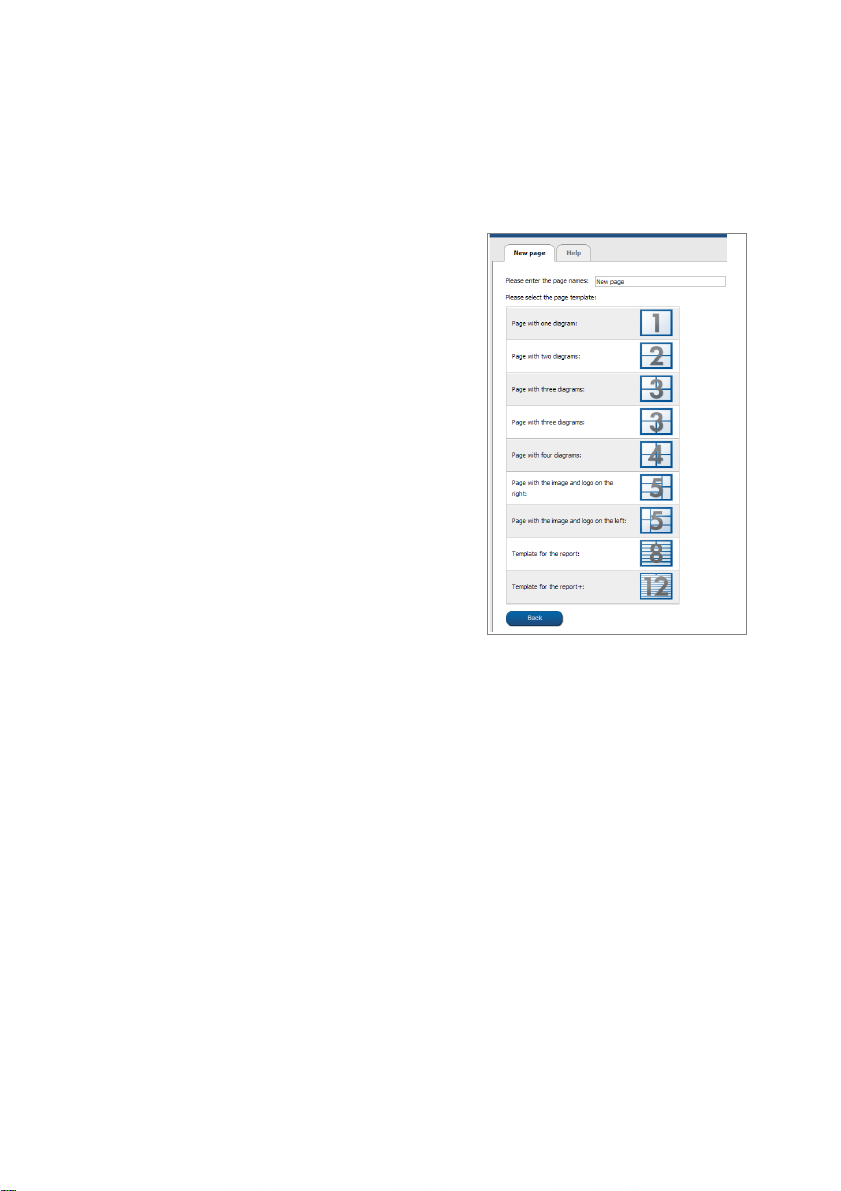
2. Select [New Page].
☑ Page templates open.
3. Enter page name in "Please enter the page name" field.
4. Select desired page template. Here you can select the page layout. You can place different
content in the page sections. TIP: In page templates 8 and 12, the height of the two upper
sections is limited. These sections are only suitable for small images such as logos.
☑ The "Page Configuration" page opens.
5. In the "Module type" field in one section of the page, select the desired page content.
6. Select [Create] to create desired page content (see Section 6.3 ”Generating Page Content”
(page21)).
20 SPortal-WB-CLCON-BA-en-25 User Manual
Page 21
SMA Solar Technology AG 6 Page Design
6.3 Generating Page Content
6.3.1 Overview of Page Content
You can choose between the following page contents:
Page content Content
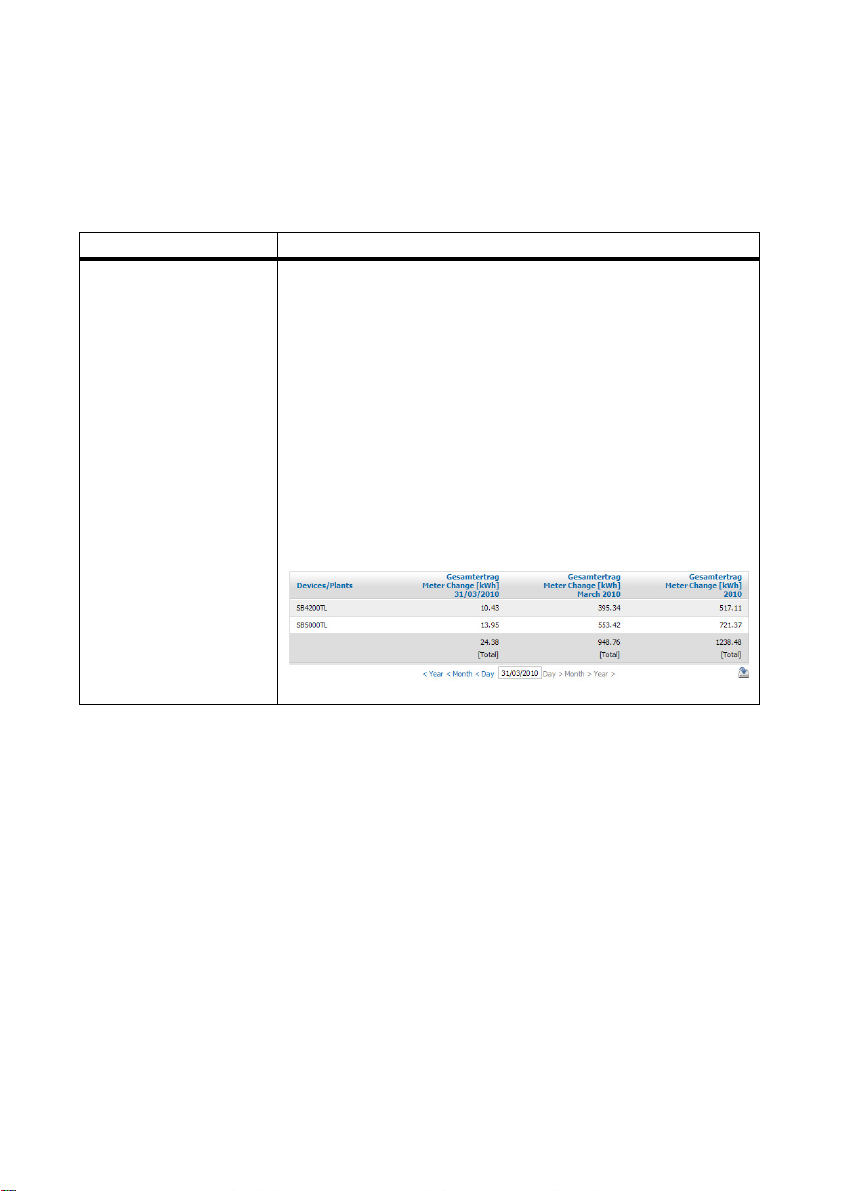
Table You can display the following data in tables:
• Channel values of the devices
Which channel values can be selected depends on the device.
•Channel values of the entire plant:
–CO
savings
2
–Total yield
– Performance ratio
–Power
– Feed-in compensation
– Specific plant yield
Example of table:
User Manual SPortal-WB-CLCON-BA-en-25 21
Page 22
6 Page Design SMA Solar Technology AG
Page content Content
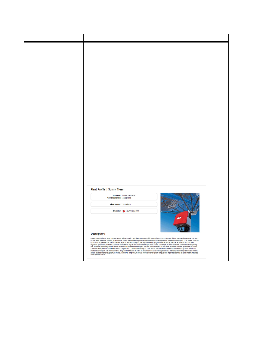
Plant profile You can also use this information on your customised pages.
Information in the plant profile:
•Plant name
•Location
•Operator
• Date commissioned
•Plant power
• Annual production
•CO
savings
2
•PV modules
•Azimuth angle
•Tilt angle
•Tracking
•Inverter
• Communication
•Description
Example of plant profile:
22 SPortal-WB-CLCON-BA-en-25 User Manual
Page 23
SMA Solar Technology AG 6 Page Design
Page content Content
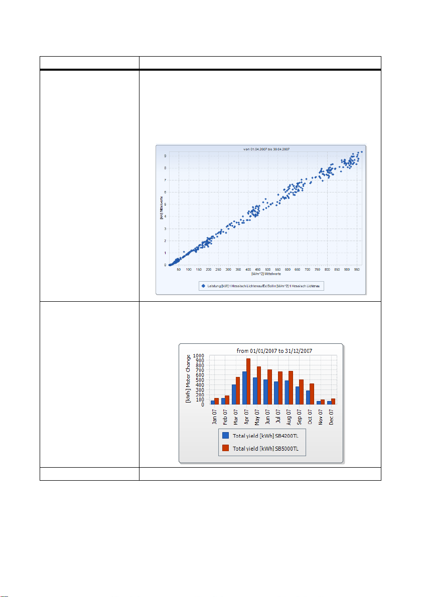
XY diagram You can display two channel values as coordinates. The x and y axes
are each assigned one channel value. The time axis is not shown.
Examples of meaningful value pairs are: plant power / irradiation
(only for plants with Sunny SensorBox), performance ratio /
irradiation.
Example of XY diagram:
Chart You can display a timeline of the channel values for devices or the
entire plant as a bar chart or line chart.
Example of chart:
Slide show You can display a slide show created previously on a photo platform.
User Manual SPortal-WB-CLCON-BA-en-25 23
Page 24
6 Page Design SMA Solar Technology AG
Page content Content
Image You can insert an image of your choice.
Requirements:
• Maximum image size: 500 kB
• Possible image formats: JPG, PNG, GIF
• Height and width: Sunny Portal adjusts the proportions of the
image to match the size of the page layout.
Plant monitoring You can display the following data:
• Communication status between the plant and Sunny Portal
• Inverter comparison status
Plant monitoring;
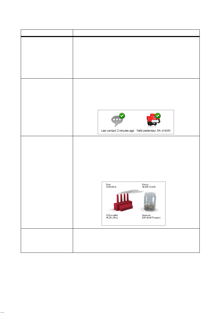
Overview You can display the following data:
• Energy of the PV plant
•CO
saved by the PV plant
2
• Feed-in compensation for the PV plant
• Standard image or a random image
Overview with standard image:
Text You can enter and format text in the editor in just the same way as in
other text editing programs. If you are familiar with HTML, you can
switch to the source code view and enter or edit the HTML code
directly. Java Script is not permitted.
24 SPortal-WB-CLCON-BA-en-25 User Manual
Page 25

SMA Solar Technology AG 6 Page Design
6.3.2 Creating Tables
Yo u ca n selec t a t able fr om the t emplat es or creat e yo ur own t able. The f ollowi ng t abl e confi gurati ons
are available:
Table configuration Meaning
Standard configuration for displaying plant
energy
Standard configuration for displaying
inverter energy
Standard configuration for displaying
specific inverter yield
User-defined Create your own table with values and time
Creating a Table with Standard Configuration
1. Select desired standard configuration.
2. Select [Next].
3. Select [Save].
4. Select [Save].
☑ The table has been created and is now displayed.
Creating a Customized Table
1. Select "User-defined".
2. Select [Next].
3. Select "Add device/plant".
4. In the "Plant/devices" field, select a plant or a device. TIP: In order to narrow your selection, use
the "Filter selection" field to choose a device type or "Plants".
5. Select [Accept].
6. In order to add further plants or devices, select "Add device/plant" and repeat previous steps.
7. Select .
☑ The "Channel Configuration" page opens.
8. In order to add a heading for this table column or line, enter the heading in the "Name" field.
9. In the "Time unit" field, choose the period for which you wish to have the values displayed.
The table includes the total yields of all plants to
which you have access. The total yields are
displayed for the current day, month and year.
The table includes the total yields of all inverters
in the active plant. The total yields are displayed
for the current day, month and year.
The t able includes the spec ific yie lds and t he total
yields of all inverters in the active plant. The
specific yields are displayed for the current day,
month and year. The total yields are displayed for
the current day.
periods tailored to your needs.
User Manual SPortal-WB-CLCON-BA-en-25 25
Page 26

6 Page Design SMA Solar Technology AG
10. In the "End date of the display" area, activate the desired end date of the display. The following
settings are possible:
current The values generated on the current date (e.g. current day, current month) will
always be displayed.
selectable You can select the date for which the values are to be displayed, e.g. a
certain day, a certain month
11. Select the desired channels in the "Channel" area.
Selectable channels
For devices, all channels which are transmitted to Sunny Portal are available. For a plant,
the calculated channels are available (CO2 avoided, energy, power, compensation,
performance ratio, specific plant yield).
The unit of the first channel selected determines the additional channels available for
selection.
12. If more than one device or plant was added, the desired calculation method can be chosen in
the "Result" field. The following settings are possible:
Sum Total of each channel content within the depicted period
Min Minimum value of each channel content within the depicted period
Mean values Mean value of each channel content within the depicted period
Max Maximum value of each channel content within the depicted period
13. Select [Accept].
☑ The "Page Configuration" page opens.
14. In order to add an additional column or line for further channels, select "Add channel" and
repeat previous steps.
15. In the "Orientation" area, activate the desired orientation of the table.
16. In the "Download file type" field, select the format for saving the table data. This will enable you
to save the data contained in the page view of the table to your computer via "Download
". The
following settings are possible:
CSV File format describing the layout of a text file to be used for the
storage or exchange of simply structured data.
ODS File format for tables with Open Document format enabling the
exchange of Office files between vari ous app lic ati ons and ope rating
systems.
XLSX File format in the Excel Workbook format supported by Microsoft as
of the Excel 2007 version.
17. Select [Save].
18. Select [Save].
☑ The table has been created and is now displayed.
26 SPortal-WB-CLCON-BA-en-25 User Manual
Page 27

SMA Solar Technology AG 6 Page Design
6.3.3 Adding a Plant Profile
1. In order to add a heading, enter the heading in the "Title" field.
2. If there are several plants in the "Plant" field, select the desired plant.
3. Activate the fields for which you wish data to be displayed.
4. Select [Save].
5. Select [Save].
☑ The plant profile has been added and is now displayed.
6.3.4 Creating an XY Diagram
Procedure:
• Configure Y axis, X axis
• Configure time settings
• Make extended configurations
Configuring Y axis, X axis
1. Select a plant or a device in the "Plant/devices" field in the "Y axis", "X axis" area. Only devices
of the active plant can be selected. TIP: In order to narrow your selection, use the "Filter
selection" field to choose a device type or "Plants".
2. Select a channel in the "Channel" field.
Selectable channels
For devices, all channels which are transmitted to Sunny Portal are available. For a plant,
the calculated channels are available (CO2 avoided, energy, power, compensation,
performance ratio, specific plant yield). The unit of the first channel selected determines the
additional channels available for selection.
3. Select [+].
☑ The table with the selected device or plant is displayed.
4. In order to add further plants or devices, repeat the previous steps.
The selection of further channels is based on the unit of the first channel
If the base unit of the first selected channel is "Watts", the only channels subsequently
selectable are those compatible with "Watts". The selection options are automatically
restricted by Sunny Portal accordingly.
5. Select the desired unit in the "Unit" field.
User Manual SPortal-WB-CLCON-BA-en-25 27
Page 28

6 Page Design SMA Solar Technology AG
6. In the "Value" field, select the channel type for the value. The following channel types are
available, depending on the channel:
Analog values
Mean values The average value of the channel over the set period.
Maximum values The highest value of the channel over the set period.
Minimum values The lowest value of the channel over the set period.
Meter channels
Meter change Increase over a period yet to be selected.
Meter reading Current total meter reading of the value.
Cum. change Cumulative (= summated) increase over a period yet to be
selected.
7. Set automatic scaling or enter own scaling values:
– Automatic scaling: activate "Automatic scaling min" and "Automatic scaling max".
– Custom scaling: enter scaling values into "Min" and "Max" fields.
Configuring time settings
1. In the "Depicted time period" field of the "Time settings" area, select the desired display period
for the diagram.
2. In the "Count of intervals" field, select how many display intervals are to be shown.
3. In the "Time unit" field, select the time unit by which the intervals should be subdivided.
4. In the "End date of the display" area, activate the desired end date of the display. The following
settings are possible:
current The values generated on the current date (e.g. current day, current month) will
always be displayed.
selectable You can select the date for which the values are to be displayed
(e.g. a certain day, a certain month).
Make extended configurations
1. In order to add a heading in the "Extended configuration" area, enter heading in the
"Diagram name" field.
2. In the "Download file type" field, select the format for savi ng the diagram. The following settings
are possible:
CSV File format describing the layout of a text file to be used for the
storage or exchange of simply structured data.
ODS File format for tables with Open Document format enabling the
exchange of Office files between vari ous app lic ati ons and ope rating
systems.
XLSX File format in the Excel Workbook format supported by Microsoft as
of the Excel 2007 version.
28 SPortal-WB-CLCON-BA-en-25 User Manual
Page 29

SMA Solar Technology AG 6 Page Design
Y1
Y2
X
3. In order to show the legend by default for this diagram, activate "Show legend".
4. In order to see the preview, open the "Preview" area. To reload the diagram after changes,
select [Update].
5. Select [Save].
6. Select [Save].
☑ The XY diagram has been created and is now displayed.
6.3.5 Creating a Diagram
A diagram consists of at least one X axis (time settings)
and one Y1 axis; the Y2 axis is optional. Several channel
va lue s wi th t he s ame uni t ca n be depicted on e ach Y ax is.
Use the Y2 axis if you want to display values having a
different unit to that of the Y1 axis.
Procedure:
• Configure the Y1 axis (Y2 axis is optional)
• Configure time settings
• Make extended configurations
Configuring the Y1 axis (Y2 axis is optional)
1. In the "Y1 axis", "Y2 axis" area of the "Plant/Devices" field, select a plant or a device.
Only devices of the active plant can be selected. TIP: In order to narrow your selection, use the
"Filter selection" field to choose a device type or "Plants".
2. Select desired channel in the "Channel" field.
Selectable channels
For devices, all channels which are transmitted to Sunny Portal are available. For a plant,
the calculated channels are available (CO
performance ratio, specific plant yield). The unit of the first channel selected determines the
additional channels available for selection.
avoided, energy, power, compensation,
2
3. Select [+].
☑ The table with the selected device or plant is displayed.
4. In order to add further plants or devices, repeat the previous steps.
Selecting additional channels
The selection of further channels is based on the unit of the first channel. If the base unit of
the first selected channel is "Watts", the only channels subsequently selectable are those
compatible with "Watts". The selection o ption s are automati cally restricted by Sunny Portal
accordingly.
5. Select the desired unit in the "Unit" field.
User Manual SPortal-WB-CLCON-BA-en-25 29
Page 30

6 Page Design SMA Solar Technology AG
6. In the "Value" field, select the channel type for the value. The following channel types are
available, depending on the channel:
Analog values
Mean values The average value of the channel over the set period.
Maximum values The highest value of the channel over the set period.
Minimum values The lowest value of the channel over the set period.
Meter channels
Meter change Increase over a period yet to be selected.
Meter reading Current total meter reading of the value.
Cum. change Cumulative (= summated) increase over a period yet to be
selected.
7. Select the type of depiction in the "Chart type" field. The following depiction types are possible:
Item Meaning
ABars
B Shaded area
C Line with markers
DLine
E Markers without line
8. Set automatic scaling or enter own scaling values:
– Automatic scaling: activate "Automatic scaling min" and "Automatic scaling max".
– Custom scaling: enter scaling values into "Min" and "Max" fields.
30 SPortal-WB-CLCON-BA-en-25 User Manual
Page 31

SMA Solar Technology AG 6 Page Design
Configuring time settings
1. In the "Depicted time period" field of the "Time settings" area, select the desired display period
for the diagram.
2. In the "Count of intervals" field, select how many display intervals are to be shown.
3. In the "Time unit" field, select into which time units the periods should be divided.
4. In the "End date of the display" area, activate the desired end date of the display. The following
settings are possible:
current The values generated on the current date (e.g. current day, current month) will
always be displayed.
selectable You can select the date for which the values are to be displayed
(e.g. a certain day, a certain month).
Making extended configurations
1. In order to add a heading in the "Extended configuration" area, enter heading in the
"Diagram name" field.
2. In the "Download file type" field, select the download format.
3. In order to show the legend by default for this diagram, activate "Show legend".
4. In order to see the preview, open the "Preview" area. To reload the diagram after changes,
select [Update].
5. Select [Save].
6. Select [Save].
☑ The diagram has been created and is now displayed.
6.3.6 Creating a Slide Show
TIP: To ensure high-quality display of the slide show, select a page template with no more than one
display module per page.
Procedure:
• Select photo album at Picasa or Flickr
• Integrate slide show into Sunny Portal
Selecting a Picasa photo album
1. Register on picasa.google.com.
2. If you have not yet uploaded any photos to Picasa, create a photo album as described at
Picasa.
3. Select photo album.
4. Select [Link to this album].
5. Select [Integrate slideshow].
☑A window opens.
User Manual SPortal-WB-CLCON-BA-en-25 31
Page 32

6 Page Design SMA Solar Technology AG
6. "Integrate slideshow" text field.
7. Select the HTML code and copy this to the clipboard.
8. Log out of Picasa and switch to Sunny Portal.
Selecting a Flickr photo album
1. Register on www.flickr.com.
2. If you have not yet uploaded any photos to Flickr, create a photo album as described at Flickr.
3. Select photo album.
4. Select [Slideshow].
☑Slide show begins.
5. Select [Publish].
☑A window opens.
6. Select [Embed HTML].
7. Select [Copy to clipboard].
8. Log out of Flickr and switch to Sunny Portal.
Integrating a slide show into Sunny Portal
1. Call up page configuration of slide show.
2. In order to add a heading, enter the heading in the "Title" field.
3. In the "Data source" field, select the name of the photo platform.
4. Copy HTML code into the "HTML code" field.
5. In order to see the preview, select [Preview].
6. Select [Save].
7. Select [Save].
☑ The slide show has been created and is now displayed.
6.3.7 Creating an Image
Image requirements:
• Maximum image size: 500 kB
• Possible image formats: JPG, PNG, GIF
• Height and width: Sunny Portal adjusts the proportions of the image to match the size of the
page layout.
Procedure:
• Upload an image from your own computer to the gallery
• Add an image from the gallery to the page
32 SPortal-WB-CLCON-BA-en-25 User Manual
Page 33

SMA Solar Technology AG 6 Page Design
Uploading an image from your own computer to the gallery
1. Select .
☑ A new window opens.
2. Select [Browse].
☑The "Select file" window opens.
3. Open desired image.
☑ The path of the image is given in the line.
4. Select [Upload selected file].
5. To upload further images, repeat the procedure.
☑ The image has been uploaded and is now displayed in the gallery.
Adding an image from the gallery to the page
1. In order to add a caption, enter caption in the "Title" field.
2. Select image by a double click.
☑Image is displayed.
3. In order to use a different image, select [Edit] and repeat previous steps.
4. Select [Save].
5. Select [Save].
☑ The image has been inserted on the page and is now displayed.
6.3.8 Creating Plant Monitoring
Requirement:
☐ Plant monitoring is configured (see Section 7.3).
1. In order to add a heading, enter the heading in the "Title" field.
2. Activate "Communication monitoring" and/or "Inverter comparison".
3. Select [Save].
4. Select [Save].
☑ Plant monitoring has been created and is now displayed.
User Manual SPortal-WB-CLCON-BA-en-25 33
Page 34

6 Page Design SMA Solar Technology AG
6.3.9 Creating an Overview
Image requirements:
• Maximum image size: 500 kB
• Possible image formats: JPG, PNG, GIF
• Height and width: Sunny Portal adjusts the proportions of the image to match the size of the
page layout.
1. Activate field with the desired value.
2. Select unit size.
3. Add an image:
– In order to use the displayed image, activate "Automatic".
– In order to use an image of your own, activate "User-defined" and select [Browse].
4. Select [Save].
5. Select [Save].
☑ The overview has been created and is now displayed.
6.3.10 Creating Text
Non-permitted HTML tags:
<SCRIPT> (hence also JavaScript), <META>, <APPLET>, <FORM>, <HTML>, <HEAD>, <FRAME>,
<IFRAME>.
1. In order to add a heading, enter the heading in the "Title" field.
2. Enter the desired text in the editor.
3. Select [Save].
4. Select [Save].
☑ The text has been created and is now displayed.
Example: Adding a current webcam image
This examp le shows how to insert the cur rent image of a webcam using the editor. Each time the page
is opened, the current image of the webcam is displayed.
Requirement:
☐ The program of the webcam always saves the current image under the same name.
1. In order to add a heading, enter the heading in the "Title" field.
2. Select .
☑ The "Image properties" window opens.
3. Enter the URL of the webcam image in the "Select image" field.
4. Select [OK].
34 SPortal-WB-CLCON-BA-en-25 User Manual
Page 35

SMA Solar Technology AG 6 Page Design
6.4 Changing/Deleting Page Contents
1. Select the name of the page in the "Visualization" menu.
☑ The selected page opens.
2. Select the "Page configuration" tab.
3. To change the page content:
– Select [Edit] in the area of the page content to be changed.
– Edit page content.
4. In order to delete page content, select [Delete] in the area of the page content to be deleted.
6.5 Changing the Page Name
1. Select the name of the page in the "Visualization" menu.
☑ The selected page opens.
2. Select the "Page configuration" tab.
3. Change the page name in the "Name of this page" field.
4. Select [Save].
6.6 Publishing Pages
You can publish the following pages:
• All pages in the "Visualization" menu
• The following pages of the "Name of your plant" menu:
–Plant profile
– Power and energy
–Annual comparison
Options for publishing:
• Present pages at www.SunnyPortal.com in the "Publicly Available Plants" area
• Present pages on the Internet
Presenting Pages on Sunny Portal in the "Publicly Available Plants" Area
1. Select the name of the desired page.
☑ The selected page opens.
2. If you have chosen a page in the "Visualization" menu, select the "Page configuration" tab.
3. If you have chosen a page in the "Name of your plant" menu, select "Configuration >
Name of page".
4. Activate the field "Also release page on www.sunnyportal.com".
☑ The link "Send page by e-mail" is displayed alongside.
User Manual SPortal-WB-CLCON-BA-en-25 35
Page 36

6 Page Design SMA Solar Technology AG
5. In order to send the page by e-mail, select "Send page by e-mail". A window for sending the
e-mail opens. Make the following settings:
– Enter the recipient's e-mail address in the "E-mail address of the recipient" field.
– In order to change the name of the sender, change entry in the "Name of the sender" field.
– In order to add a message to the recipient, enter desired text in the "Your message to the
recipient (optional)" field.
– Select [Send e-mail].
6. Select [Save].
7. In order to see a preview, select "Open page in a new window".
☑ The page is now published.
Presenting pages on the Internet
Each of your Sunny Portal pages has its own URL. You can use this URL to configure a link from
another website to your page. You can call up the URL of the page as follows:
1. Select the name of the desired page.
☑ The selected page opens.
2. Call up configuration:
– If you have chosen a page in the "Visualization" menu, select the "Page configuration" tab.
– If you have chosen a page in the "Name of your plant" menu, select "Configuration >
Name of page".
3. In order to see a preview, select "Open page in new window".
4. Copy URL from "URL of the Page" field and copy it as a link into a program for creating web
pages (e.g., Microsoft Office Frontpage) or integrate it into your own web page through a socalled iFrame.
6.7 Deleting Pages
You can delete all pages of the "Visualization" menu.
1. Select the name of the page in the "Visualization" menu.
☑ The selected page opens.
2. Select the "Page configuration" tab.
3. In order to delete the page, select [Delete page].
4. Click [Yes] to confirm.
36 SPortal-WB-CLCON-BA-en-25 User Manual
Page 37

SMA Solar Technology AG 6 Page Design
6.8 Changing Page Arrangement in the Visualization Menu
6.8.1 Creating a New Group
Once you have created a new group, you can assign pages to the group by changing the page
positions.
1. Select "Configuration > Visualization".
☑ The "Group Configuration" page opens.
2. Select [New group].
☑ The "Configure group" page opens.
3. Enter a name for the group in the "Group title" field.
4. Select [Save].
☑ The new group is now visible in the directory tree and in the "Visualization" menu.
6.8.2 Changing the Positions of Pages and Groups
Groups are moved as groups, together with the pages assigned to them. The position of the
"(without group)" group cannot be changed; it always remains at the top of the list.
1. Select "Configuration > Visualization".
☑ The "Group Configuration" page opens.
2. Select "Modify position".
3. Select the name of the group or page.
☑ Arrow keys are now active. The name of the page or group is highlighted grey.
4. Use the up or down arrow to move the page or group.
☑ The page or group moves one step at a time.
5. Keep pressing the corresponding arrow until the desired position is reached.
6. Select [Save].
6.8.3 Deleting a Group
Group and all sub-pages will be deleted permanently.
If you delete a group, all the sub-pages assigned to the group will also be permanently
erased.
1. Select "Configuration > Visualization".
☑ The "Group Configuration" page opens.
2. Select the name of the group.
3. Select [New group].
☑ The "Configure group" page opens.
4. Select [Delete] to delete the group permanently.
User Manual SPortal-WB-CLCON-BA-en-25 37
Page 38

7 System Monitoring SMA Solar Technology AG
7 System Monitoring
7.1 Overview of Monitoring Functions
Sunny Portal includes the following monitoring functions for your plant:
Monitoring Sunny Portal Function Section
Plant events System Logbook
The system logbook allows you to view
messages pertaining to events which
have occurred in your plant.
Report Configuration
If you are usi ng r epo rt c onf igu rat ion , yo u
will receive an e-mail with the events
which have occurred in your plant.
Yield, feed-in
compensation, power,
avoided
CO
2
Report Configuration
Here, you can configure the function
enabling you to receive an e-mail with
your plant data.
Inverter yields outside
of the tolerance
Plant Monitoring – Inverter
Comparison
If you set the inverter compariso n option,
you will receive an e-mail as soon as the
specific yield of an inverter exceeds the
tolerance.
Communication
between the
Sunny Portal and SMA
communication
products*
Incoming setpoints for
your plant from the
network operator
Plant Monitoring - Communication
Monitoring
If you set the communication monitoring
option, you will receive an e-mail
whenever the connection between
Sunny Portal and SMA communication
*
products
is interrupted.
Setpoint Monitoring
If you activate the setpoint monitoring,
you will receive an e-mail as soon as the
network operator transmits setpoints to
your Cluster Controller/Power Reducer
Box (e.g. to limit the active power).
*Sunny WebBox with Bluetooth, Sunny WebBox, Cluster Controller, Power Reducer Box
7.2 ”System Logbook”
(page39)
7.4 ”Report Configuration”
(page46)
7.3.3 ”Setting Inverter
Comparison” (page45)
7.3.2 ”Setting Communication
Monitoring” (page44)
7.3.4 ”Setpoint Monitoring:
Setting the E-Mail Alert”
(page45)
38 SPortal-WB-CLCON-BA-en-25 User Manual
Page 39

SMA Solar Technology AG 7 System Monitoring
7.2 System Logbook
On the page "Name of your plant > System logbook" you will receive messages from Sunny Portal
and your plant. These messages will help you to identify plant failures, for example. The figure after
the colon in the menu name shows the number of unread warning, disturbance and error messages
(system logbook: x, x = number of messages).
7.2.1 Calling up and Filtering Messages
You can filter messages in the system logbook in order to narrow down the list of messages.
1. Select "Name of your plant".
2. Select "System logbook".
3. Set the desired filters. The following settings are possible:
Go to Here you can select the date of the messages to be displayed.
Status • Non-acknowledged: non-acknowledged messages are
displayed (default setting).
• Acknowledged: acknowledged messages are displayed.
• All: both acknowledged and non-acknowledged messages are
displayed.
Plant/Devices • All: messages from Sunny Portal, the plant, Service, and the
devices are displayed.
• Portal: messages from Sunny Portal and the communication
devices are displayed.
• Plant: messages from all inverters in the active plant are
displayed.
• Devices (e.g. SB 4200TL): messages for the selected device
are displayed.
Number per page This allows you to select how many messages are to be displayed
per page.
Type This allows you to select which messages are to be displayed:
info, warning, disturbance, error.
7.2.2 Acknowledging Messages
You can acknowledge messages in order to mark them as read. This allows you to differentiate
between read and new messages.
1. Activate the fields in front of messages to be acknowledged.
2. In order to select all messages, activate "Select all".
3. To acknowledge a message immediately, select the red tick.
4. Select [Submit].
User Manual SPortal-WB-CLCON-BA-en-25 39
Page 40

7 System Monitoring SMA Solar Technology AG
7.3 Plant Monitoring
7.3.1 Overview of Plant Monitoring
The page "Name of your plant > Plant monitoring" provides information on the monitoring status of
your plant. You can set and activate various monitoring options. If desired, the plant monitoring can
send you an alert via e-mail. The "Plant Monitoring" page is subdivided into a maximum of 4 areas:
Area Meaning
Plant configuration Is only displayed if Sunny Portal has detected a new
device in your plant (see Section 10.2.7 ”Adding/
Replacing Devices (Configuration Wizard)” (page67)).
Communication monitoring Indicates whether there is connectivity between
Sunny Portal and SMA communication products* .
E-mail alerts possible.
Inverter comparison Displays whether the inverter yields of the selected
inverters are within the configured range. E-mail alerts
possible.
Setpoint monitoring This function is only available if a device is registered in
the plant which provides grid management data
(Cluster Controller or Power Reducer Box). In the
respective device, the use of Sunny Portal must be
activated and the settings for grid management carried
out.
Shows whether the plant is feeding into the electricity grid
without restrictions by the grid operator. This area only
indicates setpoints for active power limitation.
E-mail alerts possible upon reception of the following
setpoints:
•Active power limitation
• Reactive power setpoint (fixed reactive power or
phase shift factor cos-phi)
*Sunny WebBox with Bluetooth, Sunny WebBox, Cluster Controller, Power Reducer Box
40 SPortal-WB-CLCON-BA-en-25 User Manual
Page 41

SMA Solar Technology AG 7 System Monitoring
Communication monitoring:
Communication monitoring monitors the connection between Sunny Portal and the following devices:
•Sunny WebBox / Sunny WebBox with Bluetooth:
At certain time intervals, Sunny Portal checks whether Sunny WebBox has sent the data to
Su nny Por tal wit h th e sp eci fie d fr equ enc y. Y ou c an s et the f req uency w ith whi ch S unn y We bBo x
should send data to Sunny Portal in the user interface of Sunny WebBox.
• Cluster Controller:
Sunny Portal checks whether the Cluster Controller reports to the Sunny Portal with the specified
frequency. You can set the frequency with which the Cluster Controller should report to
Sunny Portal in the user interface of the Cluster Controller.
• Power Reducer Box:
Sunny Portal checks whether the Power Reducer Box reports regularly in Sunny Portal. You can
set the frequency with which the Power Reducer Box should report in Sunny Portal in the user
interface of the Power Reducer Box.
If one of these devices does not report in Sunny Portal over a prolonged period of time, an alert mail
will be sent to the given e-mail address. After the alert mail, a remin der e-m ail tha t th e er ror is s til l ac tiv e
will be sent on up to three subsequent days. The error will continue to be displayed in Sunny Portal
until the device reports to Sunny Portal again. A description of how to configure communication
monitoring is given in Section 7.3.2 ”Setting Communication Monitoring” (page44). The following
table explains the meaning of the communication monitoring symbols:
Communication monitoring
Symbol Status Meaning
Deactivated Communication monitoring is not configured.
OK Communication with Sunny Portal is OK. The time of last
contact is displayed.
Error Communication with Sunny Portal is interrupted. Use the
"Details" link to view detailed information on the time of
last contact. The following navigation options are
available:
• Link to the device properties
• Link to the parameters
• Link to device messages in the system logbook
By clicking on this bell icon, you can halt the sending of
reminder e-mails for the current error. For new errors, the
sending of a reminder e-mail will start again.
User Manual SPortal-WB-CLCON-BA-en-25 41
Page 42

7 System Monitoring SMA Solar Technology AG
Status of the Device*
Symbol Status Meaning
Error Communication with Sunny Portal is interrupted.
*Sunny WebBox with Bluetooth, Sunny WebBox, Cluster Controller, Power Reducer Box
Inverter Comparison:
Sunny Portal gives you the option of inverter comparison for plants with at least 2 PV inverters.
Sunny Central inverters are not supported.
Based on daily yield, Sunny Portal calculates the specific yield for each active inverter and compares
this once a day with the mean value of the specific yields of all inverters. Should the specific yield of
an inverter by comparison with the average specific yield be below a configurable tolerance,
Sunny Portal will inform you by e-mail. How to configure the inverter comparison option is described
in Section 7.3.3 ”Setting Inverter Comparison” (page45). The following table explains the meaning
of the inverter comparison symbols:
Inverter comparison
Symbol Status Meaning
Deactivated Inverter comparison is not activated.
OK The yields of the monitored inverters are within the
configured range. The yield of the last day is displayed.
Error Specific inverter yield is outside of tolerance for at least
one monitored inverter. Use the additional "Details" link to
view information on the actual specific yield of the
respective inverter or inverters and the comparison value
calculated from the mean values of all monitored
inverters. The following navigation options are available:
• Link to the device properties
• Link to messages in the system logbook
Setpoint monitoring:
Sunny Portal provides a setpoint monitoring option for all plants with Cluster Controller or Power
Reducer Box. In the "Setpoint monitoring" area, you can see whether the grid operator has specified
any setpoints for the active power limitation of your plant. If you wish, Sunny Portal can inform you by
e- mai l ab out inc omi ng s etp oin ts f or a ctive p owe r li mit ati on a nd reactive power setpoint (fixed reactive
power or phase shift factor cos-phi). How to configure the e-mail notification for setpoint monitoring
is described in Section 7.3.4 ”Setpoint Monitoring: Setting the E-Mail Alert” (page45).
In addition to setpoint monitoring, you should use the communication monitoring for the Cluster
Controller/Power Reducer Box (see Section 7.3.2). This monitoring option enables Sunny Portal to
identify whether or not the setpoint monitoring information may be outdated.
42 SPortal-WB-CLCON-BA-en-25 User Manual
Page 43

SMA Solar Technology AG 7 System Monitoring
The following table explains the meaning of the setpoint monitoring symbols:
Status of setpoint monitoring for active power limitation
Symbol Status Meaning
No setpoint There is no setpoint for active power limitation.
Setpoint There is a setpoint for active power limitation.
Problem with a
Cluster Controller/
There is a problem with a Cluster Controller/Power
Reducer Box.
Power Reducer Box
Status of the Power Reducer Box
Symbol Status Meaning
Ok The Power Reducer Box is working properly.
Disturbance The Power Reducer Box has received a signal from the
radio ripple control receiver that is not configured in the
Power Reducer Box.
Error There is no connection between the Power Reducer Box
and at least one Sunny WebBox.
or
There is no Sunny WebBox registered in the Power
Reducer Box.
Status of the Cluster Controller
Symbol Status Meaning
Ok The Cluster Controller is working properly.
Warning The Cluster Controller hat received a signal from the
signal source that is not configured in the Cluster
Controller.
Error There is an error in the Cluster Controller.
User Manual SPortal-WB-CLCON-BA-en-25 43
Page 44

7 System Monitoring SMA Solar Technology AG
7.3.2 Setting Communication Monitoring
Requirements:
• If you wish to monitor the communication between Sunny WebBox and Sunny Portal:
– The Sunny WebBox is registered in Sunny Portal (see Sunny WebBox manual).
– Use of Sunny Portal is activated on the user interface of the Sunny WebBox
(see Sunny WebBox manual).
• If you wish to monitor the communication between Cluster Controller and Sunny Portal:
– The Cluster Controller is registered in Sunny Portal (see user manual of the
Cluster Controller).
– The use of Sunny Portal is activated on the Cluster Controller user interface and
communication monitoring is switched on (see Cluster Controller user manual).
• If you wish to monitor the communication between the Power Reducer Box and Sunny Portal:
– The Power Reducer Box is registered in Sunny Portal (see Power Reducer Box manual).
To this end, all Sunny WebBox devices must be registered in the Power Reducer Box and at
least one of these Sunny WebBox devices must be registered in Sunny Portal.
– The use of Sunny portal is activated in the Power Reducer Box and communication
monitoring is switched on (see Power Reducer Box manual).
1. Select "Name of plant > Plant monitoring".
2. In the "Communication Monitoring" area select [Settings].
3. Set alert. The following settings are possible:
off Communication monitoring is deactivated in Sunny Portal.
liberal, tolerant,
acute
Here, you can select how fast you wish to be notified about the
interrupted communication.
The time span indicates how long Sunny Portal should wait before
sending an e-mail after the expected contact has failed.
– "acute": alert 15 minutes after contact overdue
– "tolerant": alert 1 hour after contact overdue
– "liberal": alert 3 hours after contact overdue
4. Enter the recipient's e-mail address for notifications in the "Recipient" field. If you enter several
e-mail addresses, please separate these by commas.
5. For the required devices activate the "Monitoring" field.
6. Select [Save].
44 SPortal-WB-CLCON-BA-en-25 User Manual
Page 45

SMA Solar Technology AG 7 System Monitoring
7.3.3 Setting Inverter Comparison
Depiction of the inverters in groups or individually:
The inverters are depicted as a group if they are of the same type, have the same set tolerance and
have been selected for inverter comparison. If at least one feature is different, the inverters will be
listed individually.
1. Select "Plant name > Plant monitoring".
2. In the "Inverter Comparison" area, select [Settings].
3. Enter the recipient's e-mail address for notifications in the "Recipient" field. If you enter several
e-mail addresses, please separate these by commas.
4. If necessary, change the preset generator power in the "Generator power [kWp]" field.
Sunny Portal calculates the generator power based on the nominal power of the inverter. You
can configure the generator power for each inverter (see Section 10.2.5 ”Setting the Generator
Capacity” (page65)).
5. In the "Tolerance [%]" field, change the permitted preset tolerance for inverter specific yield, if
necessary. If the specific yield is outside the tolerance range, Sunny Portal will inform you by
e-mail.
6. Activate the "Monitoring" field for the desired inverters. By doing this, the inverters will be
selected for the inverter comparison.
7. Select [Save].
7.3.4 Setpoint Monitoring: Setting the E-Mail Alert
Requirements:
☐ The Cluster Controller/Power Reducer Box is registered in Sunny Portal (see user manual of the
Cluster Controller/Power Reducer Box).
☐ The use of Sunny Portal is activated in the Cluster Controller/Power Reducer Box (see user
manual of the Cluster Controller/Power Reducer Box).
1. Select "Plant name > Plant monitoring".
2. In the "Setpoint monitoring" area, select [Settings].
3. To receive an alert by e-mail:
– Activate field "Send alert whenever control commands are received from grid operator".
– E nte r the reci pie nt' s e- mail a ddress for notifications in the "Recipient" field. If you enter several
e-mail addresses, please separate these by commas.
4. If you do not wish to receive an alert, deactivate the field "Send alert whenever control
commands are received from grid operator".
5. Select [Save].
User Manual SPortal-WB-CLCON-BA-en-25 45
Page 46

7 System Monitoring SMA Solar Technology AG
7.4 Report Configuration
Reports contain plant data or events for your plant. Sunny Portal sends reports by e-mail.
Receiving e-mails as text messages on your cell phone
You can also receive the report e-mails as a text message through your mobile network
provider or have them forwarded as a text message from your mailbox.
Direct text messages from the Sunny WebBox with optional GSM modem
If you have an installed GSM modem, the Sunny WebBox can notify you directly of error
events by e-mail and text message.
Sunny Portal takes late data into account in the following reports
If relevant data is received after the report has been sent, Sunny Portal will incorporate the
data into the subsequent report.
The following three types of report are available, and you can configure three in each case:
Report Selectable channels
Daily info report 1 to 3 • Daily yield (kWh)
• Feed-in compensation today
• Max. power today (kW)
•CO
Monthly info report 1 to 3 • Monthly yield (kWh)
• Monthly feed-in compensation
• Max. power for the month (kW)
•CO
Event report 1 to 3 For each of the three event reports you can choose four message
types from Sunny Portal, from the plant, and from Service:
• Information
• Warnings
•Disturbances
• Errors
avoided today (kg)
2
saved (kg) this month
2
46 SPortal-WB-CLCON-BA-en-25 User Manual
Page 47

SMA Solar Technology AG 7 System Monitoring
7.4.1 Configuring the Daily Info Report/Monthly Info Report
For the daily info report, the daily data for each channel, and for the monthly info report, the monthly
data for ea ch channel is t ransmit ted. You can configure three monthly info reports and three daily info
reports each containing different data. Each daily info report can be sent at a set time; the monthly
info reports are sent at the end of the month.
1. Select "Configuration / Report Configuration".
2. In the "Report configuration" field, select a daily info report or a monthly info report.
3. Select [Edit].
4. Configure report. The following settings are possible:
Activate report If the report is activated, it will be sent to the configured e-mail
address at the set interval. You can also save report settings and
activate the report later.
Recipient In the "E-mail address(es):" field, enter the recipient's e-mail address.
If you enter several e-mail addresses, please separate these by
commas.
Interval In the "Send report at:" field, select the time at which you would like
to receive the e-mail.
Content
Channel selection Activate the channel fields to be displayed in the report.
Send report as: Text: You receive the e-mail with the data in text format.
In the "Send data in:" area, activate the fields in which the data
should be displayed in the e-mail.
• Subject of the mail: The data is displayed in the subject line of
the e-mail.
• Contents of the mail: The data is displayed in the body of the email.
HTML: You receive the e-mail with the data in HTML-Format.
PDF: You receive the e-mail in text format, with the data as a PDF
attachment.
In the "Portal page to be sent:" field, select which Sunny Portal page
you wish to be sent with the e-mail. If you want to generate a
standard report page, save your report settings and create the report
manually afterwards.
5. In order to send a test report to a set e-mail address, select [Send test report].
6. Select [Save].
User Manual SPortal-WB-CLCON-BA-en-25 47
Page 48

7 System Monitoring SMA Solar Technology AG
7.4.2 Configuring an Event Report
You can set up three event reports each containing different events and to be sent at different times.
You can select four events from Sunny Portal and the plant: information, warnings, disturbances,
errors.
1. Select "Configuration / Report Configuration".
2. Select an event report in the "Report Configuration" field.
3. Select [Edit].
4. Configure report. The following settings are possible:
Activate report If the report is activated, it will be sent to the set recipients at the set
Recipient In the "E-mail address(es):" field, enter the recipient's e-mail address.
Interval In order to receive the report hourly, activate the "Hourly" field. In
Content
Send report as: Text: You receive the e-mail with the data in text format.
Maximum number of
messages in one
report
5. In order to send a test report to set e-mail addresses, select [Send test report].
6. Select [Save].
interval. You can also save report settings and activate the report
later.
If you enter several e-mail addresses, please separate these by
commas.
order to receive the report daily, activate the "Daily" field and select
the time.
In the "Portal" and "Plant" lines, activate the respective fields of the
events to be included in the report.
HTML: You receive the e-mail with the data in HTML format.
PDF: You receive the e-mail in text format, with the data as a PDF
attachment.
Select the maximum number of messages permitted in one report.
If you require empty reports to be sent as well, activate
"Send empty reports if no new events are available".
7.4.3 Manually Regenerating Reports
You can regenerate the report of a certain date at a later time. Thereafter, you can send the report to
the e-mail addresses configured in the report.
1. Select "Configuration / Report Configuration".
2. Select the desired report in the "Report Configuration" field.
3. In the "Report date" field in the "Regenerate report manually" area, select the date of the report
to be regenerated.
4. Select [Generate].
☑ Next to the button a message is displayed that the report has been sent.
48 SPortal-WB-CLCON-BA-en-25 User Manual
Page 49

SMA Solar Technology AG 8 Plant Properties
8 Plant Properties
8.1 Plant Data
On the "Configuration > Plant Properties" page, you can view or edit general information on your
PV plant. Some of the information is displayed on the "Plant profile" page.
You can perform the following settings, as explained in the sections below:
• Change general plant data
• Change the plant name
• Delete the Plant
• Set the plant power
• Change the plant description
• Create a plant image
8.1.1 Changing General Plant Data
1. Select "Configuration > Plant Properties".
2. Select the "Plant data" tab.
3. Select [Edit].
4. Change the plant data. The following settings are possible:
Name Name of the active plant. The plant identifier is used as
the default plant name. (Changing plant name, see Section
8.1.2 ”Changing the Plant Name” (page50)).
Plant identifier Plant identifier for the plant currently selected. The plant
identifier is defined when you register the plant.
Commissioning Date on which the plant was created in Sunny Portal.
Street/no. Street address to which the plant is assigned.
Postal code/city Postal code and city to which the plant is assigned.
Country Country in which the plant is located.
Federal state Federal state in which the plant is located.
Time zone Here, you can select the time zone.
Longitude Longitude and latitude of the plant location. In order to have
Latitude
Height Altitude of plant location
5. Select [Save].
User Manual SPortal-WB-CLCON-BA-en-25 49
the geodata for the location automatically entered from the
database, select "Find geodata".
Page 50

8 Plant Properties SMA Solar Technology AG
8.1.2 Changing the Plant Name
The plant identifier is used as the default plant name. You can change the plant name and assign your
plant a name. If you have several plants registered at Sunny Portal, you will be able to distinguish
better between plants by assigning them meaningful names.
1. Select "Configuration > Plant Properties".
2. Select the "Plant data" tab.
3. Select [Edit].
4. In the "Name" field, enter the desired name for the plant (e.g., "Smith House" or "WebBox Plant
South").
5. Select [Save].
8.1.3 Deleting the Plant
You cannot undo the delete process.
If you delete a plant, all devices and data related to this plant are permanently deleted.
1. Select "Configuration > Plant Properties".
1. Select the "Plant data" tab.
2. Select [Edit].
3. Select [Irretrievably delete plant].
4. To delete plant permanently, Select [Yes].
8.1.4 Setting the Plant Power
The plant power is the sum of the power of all PV modules.
Options for Configuring Plant Power:
• Enter the plant power manually
• Calculate plant power from the total power of all the inverters
Entering the Plant Power Manually
1. Select "Configuration > Plant Properties".
2. Select the "Plant data" tab.
3. Select [Edit].
4. In the "Power" area, "Plant power" field, enter the plant power.
5. In order to configure the PV module manufacturer, make a selection in the "Manufacturer" field.
6. In order to configure the module type, make a selection in the "Module type" field. The possible
settings depend on the selected manufacturer.
7. Select [Save].
50 SPortal-WB-CLCON-BA-en-25 User Manual
Page 51

SMA Solar Technology AG 8 Plant Properties
Calculating the plant power from total power of all inverters
1. Set the power of the individual inverters, see Section 10.2.5 ”Setting the Generator Capacity”
(page65).
2. Select "Configuration > Plant Properties".
3. Select the "Plant data" tab.
4. Select [Edit].
5. In the "Power" area, activate "Calculate plant power from device properties" field.
☑ Plant power is calculated and displayed.
6. Select [Save].
8.1.5 Changing the Plant Description
You can enter important features of the plant in the description. The editor can format text but does
not support HTML. The text is also displayed on the "Plant profile" page.
1. Select "Configuration > Plant Properties".
2. Select the "Plant data" tab.
3. Select [Edit].
4. Enter your description in the "Description" area.
5. Select [Save].
8.1.6 Changing/Deleting the Plant Image
The plant image is the image (A) in the menu "Name of your
plant". You can change this image. You can upload an image
from your computer or select an image from your own
Sunny Portal image gallery. You can store own images in the
gallery for later use on your pages.
Image requirements:
• Maximum image size: 500 kB
• Possible image formats: JPG, PNG, GIF
• Height and width: Sunny Portal adjusts the proportions
of the image to match the size of the page layout.
User Manual SPortal-WB-CLCON-BA-en-25 51
Page 52

8 Plant Properties SMA Solar Technology AG
Changing the plant image
1. Select "Configuration > Plant Properties".
2. Select the "Plant data" tab.
3. Select [Edit].
4. To upload an image from your computer:
– Select [Load Image] in the "Plant Image" area.
☑The "Select file" window opens.
– Select desired image.
–Select [Open].
– To change the image section, use the mouse to adjust the edges of the grey squares.
5. To select an image from the gallery:
– Select [Select from the gallery] in the "Plant image" area.
☑ The image gallery opens.
– Select the desired image by double clicking it.
– To change the image section, use the mouse to adjust the the grey squares.
6. Select [Save].
Deleting the plant image
You can delete your own plant images. If you have deleted your plant image, Sunny Portal will revert
to the default plant image.
1. Select "Configuration > Plant Properties".
2. Select the "Plant data" tab.
3. Select [Edit].
4. Select [No plant image] in the "Plant image" area.
5. Select [Save].
8.2 Changing Operator Data
You can enter the data of the plant operator in the plant properties in Sunny Portal, as described in
this section. The name of the operator is displayed on the "Plant profile" page. The operator is a
private or legal person who, for example, owns large-scale PV plants for business purposes and
makes them available for use, without necessarily being the user himself.
1. Select "Configuration > Plant Properties".
2. Select "Operator" tab.
3. Select [Edit].
4. Change operator data.
5. Select [Save].
52 SPortal-WB-CLCON-BA-en-25 User Manual
Page 53

SMA Solar Technology AG 8 Plant Properties
8.3 Parameters
This section describes how you can change the display parameters for your plant in Sunny Portal.
These settings are only relevant for the display of your plant in Sunny Portal and have no effects on
the devices. The following sections contain a description of the parameters and information on the
calculations for which Sunny Portal needs these parameters.
8.3.1 Changing the Feed-in Tariff
You can either sell the electricity generated by the plant or use it for your own consumption.
The amount of the compensation or the saving, as the case may be, should be entered here.
Sunny Portal then calculates the amount of money you are earning or saving. The feed-in tariff in
Germany is regulated by the Renewable Energy Sources Act (EEG).
1. Select "Configuration > Plant Properties".
2. Select the "Parameters" tab.
3. Select [Edit].
4. Enter amount of compensation.
5. Select currency.
6. Select [Save].
Automatic calculation of feed-in tariff - applies only to Germany
1. Select [Calculate the feed-in tariff according to the Renewable Energy Sources Act (EEG)].
☑ The "Calculate compensation" window opens.
2. Select plant type.
3. Select year of plant commissioning.
4. Select [Accept].
☑ The window closes. The amount of compensation is displayed.
5. Select [Save].
8.3.2 Changing the CO2 Avoided Factor
The CO2 factor indicates how much CO2 is produced for every single kilowatt hour of electricity
ge ner ate d in the co unt ry. Dependin g on the tec hno logy u sed and the efficiency of the facility, the CO2
factor can vary between the electric utility companies in a region. You can find out the CO
the electricity supplied in your region from your electric utility company. The CO2 factor is used by
Sunny Portal to calculate how much CO
plant.
1. Select "Configuration > Plant Properties".
2. Select the "Parameters" tab.
3. Select [Edit].
4. Enter CO2 factor in the "Factor" field or adjust with the slider.
5. Select [Save].
User Manual SPortal-WB-CLCON-BA-en-25 53
has been saved by eco-friendly power generation in your
2
factor of
2
Page 54

8 Plant Properties SMA Solar Technology AG
8.3.3 Entering the Predicted Annual Yield
The predicted annual yield is the yield to be expected from a PV plant within one year. Sunny Portal
uses a table to show how the predicted annual yield of your PV plant is distributed throughout the
months of the year.
The predicted annual yield of the PV plant is calculated from the specific annual yield (kWh/kWp) at
the location of the PV plant multiplied by the plant power in kWp. The plant power is also called
nominal power.
You can obtain the specific annual yield for your PV plant location from irradiation maps. Local
conditions such as degrees of shading or the orientation of the plant are not taken into account.
You can find out the plant power in kWp from your installer.
1. Select "Configuration > Plant Properties".
2. Select the "Parameters" tab.
3. Select [Edit].
4. Enter specific annual yield in kWh/kWp in the "Specific Annual Yield" field.
5. If the "Plant Power (Nominal Power)" field is empty, set the plant power (see Section 8.1.4
”Setting the Plant Power” (page50)).
6. Select [Save].
Changing the monthly distribution of the predicted annual yield
The monthly distribution shows how the predicted annual yield is distributed throughout the months of
the year. Given full details of the plant location, Sunny Portal can suggest a distribution. You can also
enter the distribution manually.
1. Select "Configuration > Plant Properties".
2. Select the "Parameters" tab.
3. Select [Edit].
4. If the "Plant Location" field is empty, enter details of the plant location under the "Plant Data" tab
(see Section 8.1.1 ”Changing General Plant Data” (page49)).
5. Select [Suggest a Monthly Distribution].
6. In order to enter the monthly distribution manually, enter values in the "in %" fields.
7. Select [Save].
54 SPortal-WB-CLCON-BA-en-25 User Manual
Page 55

SMA Solar Technology AG 8 Plant Properties
8.3.4 Changing the Performance Ratio
The performance ratio is a location-independent measure of the quality of a PV plant, and is therefore
often called the quality factor. The performance ratio (PR) is given in percent and describes the
relationship between the actual and target yields of the plant. It thus shows the proportion of the
energy that is actually available for feed-in to the grid after deduction of energy loss (e.g. due to
thermal losses and conduction losses ) and of the requisite operating current.
The closer the PR value determined for a plant is to 100%, the more efficiently the respective plant is
operating. In reality, a value of 100% cannot be achieved, as unavoidable losses always arise during
operation of the plant (e.g. thermal losses due to the warming of the PV modules). However,
high-performance plants can reach a performance ratio of up to 80%.
The parameters for the performance ratio are configured automatically when one of the following
devices is added to your Sunny Portal plant.
•Sunny SensorBox
• Cluster Controller with connected irradiation sensor
Cluster Controller temperature sensors
If a module temperature sensor is connected to the Cluster Controller, the module
temperature sensor readings are taken into account in the calculation of the performance
ratio. This renders the value of the performance ratio more exact. However, a satisfactory
PR calculation is also possible without a temperature sensor.
Manual adjustment of the irradiation and temperature sensor
In the following cases, you will need to adjust the parameters of the irradiation and/or temperature
sensor manually.
• If there are several Sunny SensorBox devices in the plant
• If there is a Sunny SensorBox and a Cluster Controller with connected irradiation sensor in the
plant
• If the list of parameters has been changed
• If you have replaced a Sunny SensorBox or a Cluster Controller
The reason for this is that the standard page "Performance ratio" in the "Visualization" menu is not
updated automatically.
1. Select "Configuration > Plant Properties".
2. Select the "Parameters" tab.
3. Select [Edit].
4. In the "Irradiation sensor" field, select the sensor based on the serial number of the
Cluster Controller / Sunny SensorBox.
User Manual SPortal-WB-CLCON-BA-en-25 55
Page 56

8 Plant Properties SMA Solar Technology AG
5. Select the type of irradiation sensor. The following settings are possible:
ExtSolIrr External irradiation sensor
IntSolIrr Internal irradiation sensor (only with Sunny SensorBox)
6. In the "Temperature sensor" field, select the sensor based on the serial number of the
Cluster Controller / Sunny SensorBox.
7. Select type of temperature sensor. The following settings are possible:
TmpAmb Ambient temperature sensor
TmpMdul Module temperature sensor
8. In the "Tolerance range between" field, enter the upper and lower limits of the tolerance range
for the performance ratio (default settings: 0.0 und 1.0). If the performance ratio is outside the
tolerance range, a warning will be logged in the plant logbook.
9. Select [Save].
56 SPortal-WB-CLCON-BA-en-25 User Manual
Page 57

SMA Solar Technology AG 9 Publishing Sunny Portal Pages
9 Publishing Sunny Portal Pages
There are two options for publishing the Sunny Portal pages of your PV plant:
• Release the pages on www.SunnyPortal.com
• Integrate the plant profile in your own Internet website
Releasing pages on www.SunnyPortal.com
If you release Sunny Portal pages of your plant on www.SunnyPortal.com, interested people will be
able to find your plant on www.SunnyPortal.com under "Publicly Available Plants" and view the
released pages.
1. Log into Sunny Portal with the user role "Installer" or "Plant administrator".
2. Select the desired page in the page and drop-down menu.
3. Select the "Page configuration" tab.
or
In the Contents area, select [Configuration - "Name of the Page"].
4. In the "Approval" area, activate the "Also release page on www.sunnyportal.com" checkbox.
5. To send the page by e-mail, select "Send the website by e-mail", enter the e-mail address of the
recipient, select [Send e-mail], and select .
6. Select [Save].
☑ The icon is displayed in the page and drop-down menu next to the name of the released
page. To view the released pages of the plant, select the hyperlink "Open released pages of
this plant" under "Configuration > System Presentation".
Integrating the plant profile in your own Internet website
1. Log into Sunny Portal with the user role "Installer" or "Plant administrator".
2. Select "Configuration > System Presentation".
3. In the "Plant profile" area, copy the source code of the page to the clipboard and link it into your
own website via a so-called inline frame.
User Manual SPortal-WB-CLCON-BA-en-25 57
Page 58

10 Device Settings SMA Solar Technology AG
10 Device Settings
10.1 Calling Up and Filtering the Device Overview
On the "Device overview" page, you can view details of all devices in your plant and make
device-specific settings. The "Overview of New Devices" tab will only be visible if Sunny Portal has
detected new devices in your plant.
1. Select "Configuration > Device Overview".
☑ The device overview of all devices in the active plant now opens.
Item Meaning
A Settings for filtering the device overview
B Device Overview
C Device name: name of the device
D Serial number: serial number of the device
E Product group: device group, e.g., Sunny Boy 4200TL
F
G
H Properties: opens tab with device properties of the device, see Section
I Parameters: opens the "Parameters" tab of the device, see Section
K Logbook: opens the "System logbook" tab with filtered messages for
* = active, = deactivated
*
Data collection: indicates whether the data of this device is to be used on
your Sunny Portal pages, see Section 10.2.1 ”Activating/Deactivating the
Device” (page63).
*
Monitoring: indicates whether the device (inverter, Sunny WebBox) is
participating in plant monitoring, see Section 7.3 ”Plant Monitoring”
(page40).
10.2 ”Calling Up Device Properties” (page59).
10.3 ”Calling up the Parameters of a Device” (page68).
this device, see Section 7.2 ”System Logbook” (page39).
58 SPortal-WB-CLCON-BA-en-25 User Manual
Page 59

SMA Solar Technology AG 10 Device Settings
2. To filter the device overview, set the desired filters. The following settings are possible:
Device name Enter the complete name of a device or parts of a device name.
Serial number Enter the complete serial number of the device or parts of the serial
number.
Devices Select the required device class, e.g., PV inverter or sensor.
Data collection Select the status of the required devices.
• all: both activated and deactivated devices are displayed.
• active: only activated devices are displayed.
• deactivated: only deactivated devices are displayed.
3. Select [Refresh].
4. To delete filter settings, select [Reset]. TIP: You can sort the devices in the table of the device
overview in ascending or descending order by clicking on a blue entry in the table header
(device, serial number, device active).
10.2 Calling Up Device Properties
1. Select "Configuration > Device Overview".
2. In the device line, select the icon for device characteristics.
☑The device characteristics window opens.
Explanation of Device Properties:
Designation Meaning
Data collection Indicates whether the device is activated in Sunny Portal
(see Section 10.2.1 ”Activating/Deactivating the Device”
(page63)). Activated devices are used in Sunny Portal,
deactivated devices are not used.
= Device is activated in Sunny Portal.
= Device is deactivated in Sunny Portal.
Product group Device group, e.g. Sunny Boy 4200TL
Serial number Serial number of the device
IP address
(only with Sunny WebBox and
Cluster Controller)
MAC address
By selecting the IP address, you can access the user
interface of the Sunny WebBox or Cluster Controller
directly. To do this, you may need to set up port
forwarding in your router (see router manual).
MAC address of the Sunny WebBox
(only with Sunny WebBox)
Manufacturer Device manufacturer
User Manual SPortal-WB-CLCON-BA-en-25 59
Page 60

10 Device Settings SMA Solar Technology AG
Designation Meaning
Device name Device name
The s erial number o f the d evice is displ ayed a s the default
device name (to change the name, see Section 10.2.2
”Changing the Device Name” (page64)).
Description Space for comments on the device (see Section 10.2.3
”Changing the Device Description” (page64))
Irradiation sensor connected
(only with Cluster Controller)
In dic ates whet her an irradi ati on s ensor is c onn ected to t he
Cluster Controller.
= Irradiation sensor connected
= No irradiation sensor connected
Module temperature sensor
connected
(only with Cluster Controller)
Outside temperature sensor
connected
(only with Cluster Controller)
Phase (L1, L2, L3)
(only with inverters)
Generator capacity
(only with inverters)
Meter reading total yield
(only with inverters)
Communication monitoring
(only with Sunny WebBox,
Cluster Controller and
Power Reducer Box)
Inverter comparison
(only with inverters)
Indicates whether a module temperature sensor is
connected to the Cluster Controller.
= Module temperature sensor connected
= No module temperature sensor connected
Indicates whether an outside temperature sensor is
connected to the Cluster Controller.
= Outside temperature sensor connected
= No outside temperature sensor connected
Phases to which the device is connected
(see Section 10.2.4 ”Setting the Phase” (page64)).
= The device is connected to this phase.
= The device is not connected to the phase or the
phase is not yet configured.
Total power of all PV modules connected to a PV inverter.
Meter reading of inverter total yield during the current day
Shows the settings of this Sunny WebBox/this
Cluster Controller/this Power Reducer Box for
communication monitoring (see Section ”Explanation of
device properties – Communication monitoring (only for
Sunny WebBox, Cluster Controller and Power Reducer
Box):” (page61)).
Shows the settings of the inverter for this inverter
comparison (see Section ”Explanation of device
properties - Inverter comparison (only for inverters):”
(page61)).
60 SPortal-WB-CLCON-BA-en-25 User Manual
Page 61

SMA Solar Technology AG 10 Device Settings
Explanation of device properties – Communication monitoring (only for Sunny WebBox,
Cluster Controller and Power Reducer Box):
Designation Meaning
Monitoring Here you can activate or deactivate communication
monitoring for this communication device* .
Alert after Indicates the period of time with no contact between
Sunny Portal and this communication device* which must
elapse before you receive an e-mail.
Interval Shows the frequency with which the communication
device* sends data to the Sunny Portal (configuration via
user interface of the communication device*).
Time period Indicates in which period the communication device*
sends data to the Sunny Portal (configuration via user
interface of the communication device*).
*Sunny WebBox, Cluster Controller or Power Reducer Box.
Explanation of device properties - Inverter comparison (only for inverters):
Designation Meaning
Monitoring Here you can activate or deactivate the inverter
comparison for this inverter.
Tolerance [%] Here, you can enter the permissible tolerance for the
specific yield of this inverter. If the specific yield is outside
the tolerance range, Sunny Portal will inform you by
e-mail.
User Manual SPortal-WB-CLCON-BA-en-25 61
Page 62

10 Device Settings SMA Solar Technology AG
Explanation of device properties – Device status of the Cluster Controller
• To display the device status of the Cluster Controller, select the "Device Characteristics" page
of the Cluster Controller and go to the "Device status" tab.
Designation Meaning
Device status Indicates the device status of the Cluster Controller
(see page 43).
Grid management Indicates whether grid management is activated in the
Cluster Controller (see the Cluster Controller user
manual).
Active power limitation*
Parameter for active power limitation
Cos Phi setpoint* Parameter for the cos Phi setpoint
Target value Indicates the current target value for active power
limitation or the cos Phi setpoint. The target value is
specified by the network operator.
Actual set value Indicates the current actual set value for active power
limitation or the Cos phi setpoint. The actual set value is
sent to the inverters by the Cluster Controller.
Source of target value Indicates the type of signal source.
Last contact Shows the date and time of the last contact between the
Cluster Controller and the Sunny Portal.
*The data for active power limitation and cos Phi setpoint are displayed when the respective function is activated.
62 SPortal-WB-CLCON-BA-en-25 User Manual
Page 63

SMA Solar Technology AG 10 Device Settings
Explanation of device properties – Device status of Power Reducer Box
• To display the device status of the Power Reducer Box, select the "Device Characteristics" page
of the Cluster Controller and go to the "Device status" tab.
Designation Meaning
Device status Indicates the device status of the Power Reducer Box
(see page 43).
Operating mode Displays the operating mode for grid management
which is configured in the Power Reducer Box, e.g.,
"Active power limitation“ (see user manual of the
Power Reducer Box).
Setpoint (target) Indicates the current target value for grid management.
The target value is specified by the network operator.
Setpoint (actual) Indicates the current actual value for grid management.
The actual value is transmitted to the plant by the
Power Reducer Box.
Status of the inputs Indicates the status of the digital inputs from the ripple
control receiver.
•"Open": no signal
• "K1 + K2" (example): relay 1 and relay 2 are
closed.
Communication monitoring
deactivated/activated
Indicates whether the communication monitoring for the
Power Reducer Box is switched on or off.
10.2.1 Activating/Deactivating the Device
1. If you want to remove a d evice from you r plant or if you do not want to have a device displayed
on Sunny Portal, you can deactivate the device on Sunny Portal. The data of the deactivated
device is then no longer available for calculating diagrams and tables. However, in contrast to
the deletion of a device (see Section 10.2.6 ”Deleting a Device” (page67)), the data of a
deactivated device is retained on Sunny Portal Select "Configuration > Device Overview".
2. In the device line, select the icon for device characteristics.
☑ The device characteristics window opens.
3. Select [Edit].
4. In order to activate a device, activate the "Data collection" field.
5. In order to deactivate a device, deactivate the "Data collection" field.
6. Select [Save].
User Manual SPortal-WB-CLCON-BA-en-25 63
Page 64

10 Device Settings SMA Solar Technology AG
10.2.2 Changing the Device Name
The serial number of the device is displayed as the default device name.
1. Select "Configuration > Device Overview".
2. In the device line, select the icon for device characteristics.
☑ The device characteristics window opens.
3. Select [Edit].
4. Enter new name in the "Name" field.
5. Select [Save].
10.2.3 Changing the Device Description
1. Select "Configuration > Device Overview".
2. In the device line, select the icon for device characteristics.
☑ The device characteristics window opens.
3. Select [Edit].
4. Enter your remarks on the device in the "Description" field.
5. Select [Save].
10.2.4 Setting the Phase
You can set the phase into which the inverter feeds.
1. Select "Configuration > Device Overview".
2. In the device line, select the icon for device characteristics.
☑ The device characteristics window opens.
3. Select [Edit].
4. Activate the respective field L1, L2, or L3 in the "Phase" area.
5. Select [Save].
64 SPortal-WB-CLCON-BA-en-25 User Manual
Page 65

SMA Solar Technology AG 10 Device Settings
10.2.5 Setting the Generator Capacity
You only need to make the settings in this section if Sunny Portal is to calculate the entire power of
your plant or if you are using the "Inverter comparison" function. Sunny Portal calculates the plant
power from the aggregate power of the inverters (generator capacity).
Options for setting the generator capacity:
• Enter the power of an inverter manually
• Configure the power of an inverter via multiple strings
Entering the power of an inverter manually
1. Select "Configuration > Device Overview".
2. In the inverter line, select the icon for the device characteristics.
☑The device characteristics window of the inverter opens.
3. Select [Edit].
4. Enter inverter power in the "kWp" field under "Generator power".
5. Select [Save].
6. Activate calculation, see Section 8.1.4 ”Setting the Plant Power” (page50), paragraph
”Calculating the plant power from total power of all inverters” (page51).
Configuring the power of an inverter via multiple strings
1. Select "Configuration > Device Overview".
2. In the inverter line, select the icon for the device characteristics.
☑ The device characteristics window opens.
3. Select [Edit].
4. Call up page for string settings:
– To add a new string, select [Add string].
– To copy an existing string, select [Copy] in the string line and then edit it.
– To edit an existing string, select [Edit] in the string line.
☑ The menu for configuring the string opens.
User Manual SPortal-WB-CLCON-BA-en-25 65
Page 66

10 Device Settings SMA Solar Technology AG
5. Configure the string. The following settings are possible:
Designation Enter name for the string
Manufacturer Select the module manufacturer
Module type Select the type of module
You must set the manufacturer first. The menu content will vary
depending on the selected manufacturer.
Module power This data is entered automatically when you select the module
Module surface
Efficiency
type. You can enter adjustments in the fields using the arrows or
the arrow keys on the keyboard.
Number of modules Enter the number of modules on the string
Azimuth angle You can enter the azimuth angle of the string module surfaces
here. The azimuth angle indicates the number of degrees by which
the module surfaces deviate from an exact southern orientation.
•Tracking
If your modules track the sun automatically, activate this
field.
Tilt angle Set the tilt angle of the string module surfaces. The tilt angle
indicates the number of degrees by which the module surfaces
deviate from the horizontal.
•Optimized
If your plant is optimized for latitude, activate this field. In
Germany, the optimum orientation is 30° from the
horizontal.
Description Enter comments
6. Select [Accept].
☑ The device characteristics page opens. The string is configured.
7. Select [Save].
8. Activate calculation, see Section 8.1.4 ”Setting the Plant Power” (page50), paragraph
”Calculating the plant power from total power of all inverters” (page51).
66 SPortal-WB-CLCON-BA-en-25 User Manual
Page 67

SMA Solar Technology AG 10 Device Settings
10.2.6 Deleting a Device
If you delete a device, all the data of that device is deleted permanently. Check
in advance whether it is sufficient to deactivate the device (see Section 10.2.1
”Activating/Deactivating the Device” (page63)).
Replacing a device using the configuration wizard
After you have replaced a device using the configuration wizard (see Section 10.2.7
”Adding/Replacing Devices (Configuration Wizard)” (page67)), the replaced device is
automatically deleted.
1. Select "Configuration > Device Overview".
2. In the device line, select the icon for device characteristics.
☑ The device characteristics window opens.
3. Select [Edit].
4. Select [Delete].
☑ A security prompt opens.
5. To delete the device permanently, select [Delete].
10.2.7 Adding/Replacing Devices (Configuration Wizard)
You can add new devices to Sunny Portal or replace devices as soon as the communication device
st art s tr ans mit tin g da ta f rom the new devic es t o Su nny Por tal . Sunny Portal recognizes the new devices
and opens the configuration wizard automatically when you log into Sunny Portal with your access
data. From a total of 10 or more devices, you can add several devices simultaneously by clicking the
button underneath the list. After you have replaced a device using the configuration wizard, the
replaced device is automatically deleted in Sunny Portal.
1. To open the configuration wizard manually, select either "Name of Your Plant >
Plant Monitoring" or "Configuration > Device Overview > Overview of New Devices".
☑ The configuration wizard opens.
2. Select [Set up device now].
3. To add a device, select in the device line and follow the instructions of the configuration
wizard.
4. To replace a device, select in the device line and follow the instructions of the configuration
wizard.
5. To add or replace another device, repeat the above steps.
User Manual SPortal-WB-CLCON-BA-en-25 67
Page 68

10 Device Settings SMA Solar Technology AG
10.3 Calling up the Parameters of a Device
The parameters are described in the respective device manual. The device parameters are read-only
and cannot be changed. If you want to change the parameters, use the Sunny WebBox or the
Sunny Explorer software from SMA Solar Technology AG.
1. Select "Configuration > Device Overview".
☑ The device overview of all devices in the active plant now opens.
2. In the device line, select the parameter icon.
☑ The device parameters open.
3. In order to view the history of a parameter, select the history icon.
68 SPortal-WB-CLCON-BA-en-25 User Manual
Page 69

SMA Solar Technology AG 11 User Management
11 User Management
11.1 User Concept with Roles and Privileges
You can create additional users in your Sunny Portal, so that they will have access to your
Sunny Portal. You can assign roles to users. Roles differ in the privileges the user enjoys in your
Sunny Portal, for example, whether the user is authorized to create a new page. The following roles
are possible:
•Guest
• Standard user
• Installer
• Plant administrator
Overview of Roles and Privileges
Privileges Role
Guest Standard Installer Administrator
Login ✓✓✓✓
View pages ✓✓✓✓
View and change user
information
Change password – ✓ ✓ ✓
View plant properties – ✓ ✓ ✓
View device properties – ✓ ✓ ✓
View report configuration – ✓ ✓ ✓
View, change and delete pages – – ✓ ✓
View and change plant
properties
View and change device
properties
View and change report
configuration
View and change calculated
channels
View system logbook and
confirm entries
Import data – – ✓ ✓
View user management – – – ✓
Create and delete users and
assign roles
✓✓✓✓
––✓✓
––✓✓
––✓✓
––✓✓
––✓✓
–––✓
User Manual SPortal-WB-CLCON-BA-en-25 69
Page 70

11 User Management SMA Solar Technology AG
11.2 Creating a New User
User is notified by e-mail
If you create a new user, he will receive an e-mail informing him that he has access to your
Sunny Portal under this e-mail address. If the new user is not yet registered in Sunny Portal,
he will also receive an automatically generated password.
1. Select "Configuration > User Management".
2. Select [New User].
3. In the "E-mail address:" field, enter the e-mail address of the new user.
4. In the "Roles" area, activate the desired role. The "Standard user" role is activated by default.
5. Select [Save].
☑ The new user has been created and will receive an e-mail with the access details.
11.3 Changing User Privileges
1. Select "Configuration > User Management".
2. In the user line, select the edit icon.
3. In the "Roles" area, activate the desired role.
4. Select [Save].
11.4 Changing User Information
Every user created (except for "Guest") receives his own "User Information" page. On this page, each
user can enter his own data.
1. Select "User Info/Logout".
2. Select "User Information".
3. Select [Edit].
4. Fill in the fields.
5. Select [Save].
70 SPortal-WB-CLCON-BA-en-25 User Manual
Page 71

SMA Solar Technology AG 11 User Management
11.5 Deleting a User
Never delete the e-mail address used by the communication product.
Never delete the user whose e-mail address is used by the communication product
(e. g. Sunny WebBox, Cluster Controller) to send data to Sunny Portal. Otherwise, the
communication product will no longer be able to send data to Sunny Portal. If you want to
enter a new e-mail address in the communication product, proceed as follows:
• Create a user with the new e-mail address in Sunny Portal and assign the role of
"Administrator" or "Installer" (see Section 11.2 ”Creating a New User” (page70)).
• In the communication product, enter the new e-mail address for sending data to
Sunny Portal.
• In Sunny Portal, delete the user with the old e-mail address as described below.
1. Select "Configuration > User Management".
☑ The "User Management" page opens.
2. In the line of the user, select the delete icon.
☑ A security prompt opens.
3. Click [Yes] to delete the user.
11.6 Changing your Password
Each user created (except "Guest") can change his password for Sunny Portal access.
1. Select "User Info/Logout".
2. Select "User Information".
3. Select "If you want to change your password, please click here" under the table.
☑ The "Change password" tab opens.
4. Enter the previous password in the "Old password" field.
5. Enter new password in the "New password" field.
6. Enter new password again in the "New password (re-enter)" field.
7. Select [Save].
User Manual SPortal-WB-CLCON-BA-en-25 71
Page 72

12 Troubleshooting SMA Solar Technology AG
12 Troubleshooting
Problem Cause Remedy
The pop-up window does not
open.
Po p-u p wi ndo ws a re b loc ked by
the web browser or additional
programs (e.g. Google
Toolbar).
Enable pop-ups in the web
browser and any additional
programs.
72 SPortal-WB-CLCON-BA-en-25 User Manual
Page 73

SMA Solar Technology AG 13 Glossary
13 Glossary
Azimuth angle
The azimuth angle indicates by how many degrees the module surface deviates from the compass
point due south. In the southern hemisphere, it indicates the deviation from due north. If the module
surfaces are facing due south, the azimuth angle is 0°.
Generator capacity
The generator capacity is the maximum power of the PV modules that are connected to one inverter.
kWp
See peak power
Nominal power (kWp)
See peak power
Peak power (kWp)
The peak power is the maximum power output calculated for a PV module under STC (Standard Test
Conditions).
The peak power is measured in watt peak (Wp), kilowatt-peak (kWp), or megawatt-peak (MWp).
Peak power is also called nominal power.
STC: standard test conditions in the laboratory under which the electrical characteristics of a PV
module are measured. This enables the comparison of different PV modules. The PV modules are
subjected to vertical irradiation of 1,000 W/m
of 1 m/s. The electrical characteristics are then measured. The test conditions are designed to
correspond to the ideal ambient conditions for operation of an installed PV module.
Plant power in kWp
The plant power in kWp (kilowatt peak) is the maximum possible plant power. The plant power in
kWp is also known as the nominal power of the plant.
The peak power of a PV plant is the sum of the peak powers of all PV modules installed (see peak
power of a PV module). The peak power of a PV plant is used to compare the plant yield and plant
costs with other PV plants, for example. The peak power of a PV plant is often referred to as
"plant power (kWp)".
An installed plant can rarely achieve peak power because it is not installed in laboratory conditions.
Predicted annual yield (kWh)
The predicted annual yield of a plant is calculated using the specific annual yield (kWh/kWp) at the
plant location and the plant power in kWp (also known as nominal power).
You can obtain the specific annual yield for your PV plant location from irradiation maps.
Specific annual yield (kWh/kWp) x nominal power (kWp) = predicted annual yield (kWh)
2
, an ambient temperature of 25°C, and a wind speed
Example: Calculation of the predicted annual yield
The specific annual yield at a PV plant location is approximately 900 kWh/kWp. The nominal
power of the PV plant is 4.8 kWp.
Predicted annual yield = 900 kWh/kWp x 4.8 kWp = 4,320 kWh
User Manual SPortal-WB-CLCON-BA-en-25 73
Page 74

13 Glossary SMA Solar Technology AG
PV module
Electrical circuitry of several PV cells that are encapsulated in an enc los ure to p rot ect the sen sit ive cel ls
against mechanical stresses and environmental influences.
Specific annual yield (kWh/kWp)
The specific annual yield is a calculated average value of specific plant yield values of different PV
plants for a location. You can obtain the specific annual yield for your PV plant location from
irradiation maps. You can assess the efficiency of your PV plant by comparing the specific plant yield
of your PV plant with the specific annual yield for your PV plant location.
Specific plant yield (kWh/kWp)
The specific plant yield is a key figure that describes the efficiency of a PV plant, regardless of its size.
The specific plant yield is dependent on the irradiation at the location, the ambient temperature,
shading, tilt and azimuth angle of the PV modules, and the module and inverter power.
You can assess the efficiency of your PV plant by comparing the specific plant yield of your PV plant
with the specific annual yield for your PV plant location.
The specific plant yield is calculated from the actual measured energy yield (kWh) of a PV plant for
a specific period (e.g. a year or a month) divided by the peak power (kWp) of the PV plant.
Example calculation of the specific plant yield for one year
Your PV plant consists of 40 PV modules, each with a peak power of 120 Wp (watt peak) as per
manufacturer specification. Hence, your PV plant has a peak power of
40 x 120 Wp = 4,800 Wp = 4.8 kWp.
To calculate the specific plant yield of your PV plant for the year 2011, for example, you will need
the actual (measured) energy yield of your PV plant for 2011, e.g. 3,200 kWh. You can now
calculate the specific plant yield of your PV plant for the year 2011: 3,200 kWh divided by
4.8 kWp = 666 kWh/kWp in 2011.
Tilt angle
The tilt angle indicates by how many degrees the module surface deviates from the horizontal.
74 SPortal-WB-CLCON-BA-en-25 User Manual
Page 75

SMA Solar Technology AG 14 Contact
14 Contact
If you have technical problems concerning our products, please contact the SMA Service Line. We
require the following information in order to provide you with the necessary assistance:
• Plant name, plant identifier, or e-mail address (see Section 8.1).
• Type and serial number of communication product (see manual of the communication product)
• Type of data transmission (network, analog, ISDN, GSM)
• If there is a dial-up option to the communication device: phone number
SMA Solar Technology AG
Sonnenallee 1
34266 Niestetal, Germany
www.SMA.de
SMA Service Line
Inverters: +49 561 9522 1499
Communication: +49 561 9522 2499
Fax: +49 561 9522 4699
E‑Mail: ServiceLine@SMA.de
User Manual SPortal-WB-CLCON-BA-en-25 75
Page 76

Legal Restrictions SMA Solar Technology AG
The information contained in this document is the property of SMA Solar Technology AG. Publishing its content, either partially or
in full, requires the written permission of SMA Solar Technology AG. Any internal company copying of the document for the
purposes of evaluating the product or its correct implementation is allowed and does not require permission.
SMA Factory Warranty
The current warranty conditions come enclosed with your device. These are also available online at www.SMA-Solar.com and can
be downloaded and are available on paper from the usual sales channels if required.
Trademarks
All trademarks are recognised even if these are not marked separ ately . Missin g desi gnation s do no t mean th at a pr oduct or bra nd
is not a registered trademark.
The Bluetooth
SMA Solar Technology AG is under licence.
QR Code
SMA Solar Technology AG
Sonnenallee 1
34266 Niestetal
Germany
Tel. +49 561 9522-0
Fax +49 561 9522-100
www.SMA.de
E-Mail: info@SMA.de
© 2004 to 2012 SMA Solar Technology AG. All rights reserved
®
word mark and logos are registered trademarks owned by Bluetooth SIG, Inc. and any use of such marks by
®
is a registered trademark of DENSO WAVE INCORPORATED.
76 SPortal-WB-CLCON-BA-en-25 User Manual
Page 77

XXX4."4PMBSDPN
4."4PMBS5FDIOPMPHZ
4."4PMBS5FDIOPMPHZ"(
XXX4."EF
4.""NFSJDB--$
XXX4.""NFSJDBDPN
4."5FDIOPMPHZ"VTUSBMJB1UZ-UE
XXX4.""VTUSBMJBDPNBV
4."#FOFMVY413-
XXX4."#FOFMVYDPN
4."#FJKJOH$PNNFSDJBM$P-UE
XXX4."$IJOBDPN
4."$[FDI3FQVCMJDTSP
XXX4."$[FDIDPN
4."'SBODF4"4
XXX4."'SBODFDPN
4.")FMMBT"&
XXX4.")FMMBTDPN
4."*C©SJDB5FDOPMPHB4PMBS4-
XXX4."*CFSJDBDPN
4."*UBMJB4SM
XXX4."*UBMJBDPN
4."5FDIOPMPHZ,PSFB$P-UE
XXX4.",PSFBDPN
 Loading...