

SMA SUNNY TRIPOWER 12000TL-US, SUNNY TRIPOWER 20000TL-US, SUNNY TRIPOWER 24000TL-US, SUNNY TRIPOWER 30000TL-US, SUNNY TRIPOWER 15000TL-US Installation Manual
SUNNY TRIPOWER
12000TL-US / 15000TL-US / 20000TL-US /
24000TL-US / 30000TL-US
STPTL-US-10-IA-xx-17 | 98-109400.02 | Version 1.7
ENGLISH
Installation Manual
ESPAÑOL
Instrucciones de instalación
FRANÇAIS
Instructions d’installation

Legal Provisions
Copyright©2015SMA Solar Technology America LLC. All rights reserved.
No part of this document may be reproduced, stored in a retrieval system, or transmitted, in any
form or by any means, be it electronic, mechanical, photographic, magnetic or otherwise, without
the prior written permission of SMA Solar Technology America, LLC.
Neither SMA Solar Technology America,LLC nor SMA Solar Technology Canada Inc. makes
representations, express or implied, with respect to this documentation or any of the equipment
and/or software it may describe, including (with no limitation) any implied warranties of utility,
merchantability, or fitness for any particular purpose. All such warranties are expressly disclaimed.
Neither SMA Solar Technology America,LLC nor its distributors or dealers nor SMA Solar
Technology Canada Inc. nor its distributors or dealers shall be liable for any indirect, incidental, or
consequential damages under any circumstances.
(The exclusion of implied warranties may not apply in all cases under some statutes, and thus the
above exclusion may not apply.)
Specifications are subject to change without notice. Every attempt has been made to make this
document complete, accurate and up-to-date. Readers are cautioned, however, that product
improvements and field usage experience may cause SMA Solar Technology America LLC and/or
SMA Solar Technology Canada Inc. to make changes to these specifications without advance
notice, or per contract provisions in those cases where a supply agreement requires advance
notice. SMA shall not be responsible for any damages, including indirect, incidental or
consequential damages, caused by reliance on the material presented, including, but not limited to,
omissions, typographical errors, arithmetical errors or listing errors in the content material.
Trademarks
All trademarks are recognized, even if not explicitly identified as such. Missing designations do not
mean that a product or brand is not a registered trademark.
Modbus® is a registered trademark of SchneiderElectric and is licensed by the
ModbusOrganization,Inc.
QRCode is a registered trademark of DENSOWAVEINCORPORATED.
Phillips® and Pozidriv® are registered trademarks of PhillipsScrewCompany.
Torx® is a registered trademark of AcumentGlobalTechnologies,Inc.
SMASolar TechnologyAmerica LLC
6020 West Oaks Blvd.
Suite 300 Rocklin, CA 95765 U.S.A.
SMA Solar Technology Canada Inc.
2425 Matheson Blvd. E
7th Floor
Mississauga, ON L4W 5K4
Canada
Legal Provisions
SMA Solar Technology America LLC
Installation ManualSTPTL-US-10-IA-xx-172
ENGLISH
Important Safety Instructions
SAVE THESE INSTRUCTIONS
This manual contains important instructions for the following products:
• STP 12000TL-US-10 (Sunny Tripower 12000TL-US)
• STP 15000TL-US-10 (Sunny Tripower 15000TL-US)
• STP 20000TL-US-10 (Sunny Tripower 20000TL-US)
• STP 24000TL-US-10 (Sunny Tripower 24000TL-US)
• STP 30000TL-US-10 (Sunny Tripower 30000TL-US)
This manual must be followed during installation and maintenance.
The product is designed and tested in accordance with international safety requirements, but as
with all electrical and electronic equipment, certain precautions must be observed when installing
and/or operating the product. To reduce the risk of personal injury and to ensure the safe
installation and operation of the product, you must carefully read and follow all instructions,
cautions and warnings in this manual.
Warnings in this Document
A warning describes a hazard to equipment or personnel. It calls attention to a procedure or
practice, which, if not correctly performed or adhered to, could result in damage to or destruction
of part or all of the SMA equipment and/or other equipment connected to the SMA equipment or
personal injury.
Symbol Description
DANGER indicates a hazardous situation which, if not avoided, will
result in death or serious injury.
WARNING indicates a hazardous situation which, if not avoided,
could result in death or serious injury.
CAUTION indicates a hazardous situation which, if not avoided,
could result in minor or moderate injury.
NOTICE is used to address practices not related to personal injury.
Warnings on this Product
The following symbols are used as product markings with the following meanings.
Warning regarding dangerous voltage
The product works with high voltages. All work on the product must only be performed as described in the documentation of the product.
Beware of hot surface
The product can become hot during operation. Do not touch the product during
operation.
Important Safety Instructions
SMA Solar Technology America LLC
Installation Manual 3STPTL-US-10-IA-xx-17
ENGLISH
Observe the operating instructions
Read the documentation of the product before working on it. Follow all safety
precautions and instructions as described in the documentation.
General Warnings
All electrical installations must be carried out in accordance with the local electrical standards
and the National Electrical Code® ANSI/NFPA 70 or the Canadian Electrical Code® CSA
C22.1. This document does not replace and is not intended to replace any local, state,
provincial, federal or national laws, regulations or codes applicable to the installation and use of
the product, including without limitation applicable electrical safety codes. All installations must
conform with the laws, regulations, codes and standards applicable in the jurisdiction of
installation. SMA assumes no responsibility for the compliance or non-compliance with such laws
or codes in connection with the installation of the product.
The product contains no user-serviceable parts.
Before installing or using the product, read all of the instructions, cautions, and warnings in this
manual.
Before connecting the product to the electrical utility grid, contact the local utility company. This
connection must be made only by qualified personnel.
Wiring of the product must be made by qualified personnel only.
General Warnings
SMA Solar Technology America LLC
Installation ManualSTPTL-US-10-IA-xx-174
ENGLISH

Table of Contents
1 Information on this Document ................................................. 8
1.1 Validity................................................................................................ 8
1.2 Target group....................................................................................... 8
1.3 Additional Information....................................................................... 8
1.4 Symbols .............................................................................................. 9
1.5 Nomenclature..................................................................................... 9
2 Safety......................................................................................... 10
2.1 Intended Use ...................................................................................... 10
2.2 Safety Information.............................................................................. 11
3 Scope of Delivery...................................................................... 13
4 Product Description................................................................... 14
4.1 Sunny Tripower .................................................................................. 14
4.2 Interfaces and Functions .................................................................... 16
5 Mounting ................................................................................... 18
5.1 Requirements for Mounting ............................................................... 18
5.2 Mounting the Inverter......................................................................... 21
6 Electrical Connection................................................................. 24
6.1 Safety during Electrical Connection.................................................. 24
6.2 Overview of the Connection Area .................................................... 25
6.2.1 View from Below.......................................................................... 25
6.2.2 Interior View................................................................................. 26
6.3 AC Connection................................................................................... 26
6.3.1 Requirements for the AC Connection......................................... 26
6.3.2 Connecting the Inverter to the Utility Grid ................................. 27
6.3.3 Connecting Additional Grounding............................................. 29
6.4 DC Connection................................................................................... 30
6.4.1 Requirements for the DC Connection......................................... 30
6.4.2 Connecting the PV Array............................................................. 31
6.5 Connecting the Inverter to the Network ........................................... 33
7 Commissioning the Inverter ..................................................... 35
Table of Contents
SMA Solar Technology America LLC
Installation Manual 5STPTL-US-10-IA-xx-17
ENGLISH

8 Configuration ............................................................................ 36
8.1 Integrating the Inverter into the Network.......................................... 36
8.2 Changing Operating Parameters...................................................... 36
8.3 Setting the Active Power Limitation in case of PV System Control
Failure ................................................................................................. 37
8.4 Deactivating the Arc-Fault Circuit Interrupter (AFCI)........................ 37
8.5 Setting SMA OptiTrac Global Peak ................................................. 37
8.6 Adjustable Parameters....................................................................... 37
9 Disconnecting the Inverter from Voltage Sources.................. 39
10 Troubleshooting ........................................................................ 41
10.1 Cleaning the Inverter.......................................................................... 41
10.2 Event Messages ................................................................................. 41
10.3 Cleaning the Fans .............................................................................. 51
10.3.1 Cleaning the Fan at the Bottom.................................................. 51
10.3.2 Cleaning the Fan on the Left-Hand Side of the Enclosure......... 52
10.4 Checking the Function of the Fans.................................................... 54
10.5 Checking the PV System for Ground Faults...................................... 55
10.6 Resetting the Operation Inhibition after Detection of an Arc Fault. 57
11 Recommissioning the Inverter.................................................. 58
12 Decommissioning the Inverter ................................................. 60
13 Procedure for Receiving a Replacement Device .................... 62
14 Technical Data........................................................................... 66
14.1 DC/AC ............................................................................................... 66
14.1.1 Sunny Tripower 12000TL-US / 15000TL-US / 20000TL-US.. 66
14.1.2 Sunny Tripower 24000TL-US / 30000TL-US............................ 68
14.2 General Data ..................................................................................... 69
14.3 Protective Devices .............................................................................. 70
14.4 Climatic Conditions............................................................................ 70
14.5 Equipment........................................................................................... 71
14.6 Torques............................................................................................... 71
14.7 Data Storage Capacity...................................................................... 71
15 Spare Parts and Accessories.................................................... 72
Table of Contents
SMA Solar Technology America LLC
Installation ManualSTPTL-US-10-IA-xx-176
ENGLISH

16 Compliance Information........................................................... 73
17 Contact....................................................................................... 74
Table of Contents
SMA Solar Technology America LLC
Installation Manual 7STPTL-US-10-IA-xx-17
ENGLISH

1 Information on this Document
1.1 Validity
This document is valid for the following device types:
• STP 12000TL-US-10 (Sunny Tripower 12000TL-US)
• STP 15000TL-US-10 (Sunny Tripower 15000TL-US)
• STP 20000TL-US-10 (Sunny Tripower 20000TL-US)
• STP 24000TL-US-10 (Sunny Tripower 24000TL-US)
• STP 30000TL-US-10 (Sunny Tripower 30000TL-US)
1.2 Target group
The tasks described in this document must only be performed by qualified persons. Qualified
persons must have the following skills:
• Knowledge of how an inverter works and is operated
• Training in how to deal with the dangers and risks associated with installing and using
electrical devices and installations
• Training in the installation and commissioning of electrical devices and installations
• Knowledge of the applicable standards and directives
• Knowledge of and compliance with this document and all safety information
1.3 Additional Information
Links to additional information can be found at www.SMA-Solar.com:
Document title Document type
"SunnyExplorer"
Software for Visualizing and Administrating a SpeedwireSystem
User Manual
"Webconnect Systems in SunnyPortal"
Registration in SunnyPortal and setting or changing operating pa-
rameters of the inverter
User Manual
"Parameter list"
Overview of All Inverter Operating Parameters and Their Configura-
tion Options
Technical Information
"Efficiency and Derating"
Efficiency and Derating Behavior of the SunnyBoy, SunnyTripower
and SunnyMiniCentral Inverters
Technical Information
"Leading Leakage Currents"
Information on the Design of Transformerless Inverters
Technical Information
1 Information on this Document
SMA Solar Technology America LLC
Installation ManualSTPTL-US-10-IA-xx-178
ENGLISH
Document title Document type
"Shade Management"
Efficient operation of partly shaded PV systems with OptiTracGlob-
alPeak
Technical Information
"Module Technology"
Use of Thin-Film and Back-Contact Modules
Technical Information
1.4 Symbols
Symbol Explanation
Information that is important for a specific topic or goal, but is not
safety-relevant
Indicates a requirement for meeting a specific goal
Desired result
A problem that might occur
1.5 Nomenclature
Complete designation Designation in this document
SMA Solar Technology America LLC SMA
SMA Solar Technology Canada Inc. SMA
SMA Speedwire Speedwire
PV system PV system
Sunny Tripower 12000TL-US / 15000TL-US / 20000TL-
US / 24000TL-US / 30000TL-US
SunnyTripower, inverter
SMA Connection Unit 1000-US Connection Unit
1 Information on this Document
SMA Solar Technology America LLC
Installation Manual 9STPTL-US-10-IA-xx-17
ENGLISH

2 Safety
2.1 Intended Use
The SunnyTripower is a transformerless PV inverter with two MPP trackers which converts the direct
current of the PV array to grid-compliant three-phase current and feeds it into the utility grid.
No galvanic isolation
• The product is not equipped with a transformer and therefore has no galvanic isolation.
Do not use grounded PV modules with the product. Only ground the mounting frame of
the PV modules. If you connect grounded PV modules to the product, the error message
Insulation resistance > Check generator occurs.
• The AC output/neutral conductor is not bonded to ground inside of the product.
The product is suitable for indoor and outdoor use.
The SunnyTripower must only be operated with PV arrays (PV modules and cabling) that are
approved by the electrical standards applicable on-site and the NationalElectricalCode® ANSI/
NFPA70 or the CanadianElectricalCode® CSAC22.1. The PV modules used must be suitable for
use with the SunnyTripower.
SMA offers the SMAConnectionUnit which is equipped with fuse holders for string fuses for up to
eight strings and with a DC load-break switch. The SMA Connection Unit combines up to four
strings to each of two output circuits. These two DC electric circuits can be connected to the two
MPP tracker inputs of the SunnyTripower (for further information see the installation manual of the
SMAConnectionUnit-US at www.SMA-Solar.com).
PV modules with a high capacity to ground may only be used if their coupling capacity does not
exceed 3.5 μF.
All components must remain within their permitted operating ranges at all times.
To protect the PV system against excessive reverse currents under fault conditions, the National
Electrical Code®, Section 690.9, requires overcurrent protection for PV source circuits where
possible short-circuit currents exceed the ampacity of source circuit conductors or the maximum
series fuse rating of the PV modules. Typically, this requires string fusing where more than two
strings are combined in parallel. Where overcurrent protection is required, National Electrical
Code®, Section 690.35, requires that both positive and negative conductors have overcurrent
protection for ungrounded PV arrays.
The product must only be used in countries for which it is approved or released by SMA and the
grid operator.
The product is not equipped with a transformer and therefore has no galvanic isolation. Do not use
grounded PV modules with the product. Only ground the mounting frame of the PV modules. If you
connect grounded PV modules to the product, the error message Insulation resistance > Check
generator occurs.
Use this product only in accordance with the information provided in the enclosed documentation
and with the locally applicable standards and directives. Any other application may cause
personal injury or property damage.
2 Safety
SMA Solar Technology America LLC
Installation ManualSTPTL-US-10-IA-xx-1710
ENGLISH
Alterations to the product, e.g. changes or modifications, are only permitted with the express written
permission of SMA. Unauthorized alterations will void guarantee and warranty claims and in most
cases terminate the operating license. SMA shall not be held liable for any damage caused by
such changes.
Any use of the product other than that described in the Intended Use section does not qualify as
appropriate.
The enclosed documentation is an integral part of this product. Keep the documentation in a
convenient place for future reference and observe all instructions contained therein.
The type label must remain permanently attached to the product.
2.2 Safety Information
This section contains safety information that must be observed at all times when working on or with
the product.
To prevent personal injury and property damage and to ensure long-term operation of the product,
read this section carefully and observe all safety information at all times.
Danger to life due to high voltages of the PV array
When exposed to sunlight, the PV array generates dangerous DC voltage which is present in the
DC conductors and the live components of the inverter. Touching the DC conductors or the live
components can lead to lethal electric shocks. If you disconnect the DC connectors from the
inverter under load, an electric arc may occur leading to electric shock and burns.
• Do not touch non-insulated cable ends.
• Do not touch the DC conductors.
• Do not touch any live components of the inverter.
• Have the inverter mounted, installed and commissioned only by qualified persons with the
appropriate skills.
• If an error occurs, have it rectified by qualified persons only.
• Prior to performing any work on the inverter, disconnect it from all voltage sources as
described in this document (see Section9, page39).
Danger to life due to electric shock in case of a ground fault
If a ground fault occurs, parts of the system may still be live. Touching live components can lead
to lethal electric shocks.
• Ensure that no voltage is present and wait five minutes before touching any parts of the PV
system or the inverter.
2 Safety
SMA Solar Technology America LLC
Installation Manual 11STPTL-US-10-IA-xx-17
ENGLISH
Risk of burns from hot surfaces
The surface of the inverter can get very hot. Touching the surface can result in burns.
• Mount the inverter in such a way that it cannot be touched inadvertently.
• Do not touch hot surfaces.
• Wait 30 minutes for the surface to cool sufficiently.
• Observe the safety messages on the inverter.
Damage to the inverter due to moisture and dust intrusion
Dust or moisture intrusion can damage the inverter and impair its functionality.
• Close all enclosure openings of the inverter tightly.
• Never open the inverter when it is raining or snowing, or the humidity is over 95%.
2 Safety
SMA Solar Technology America LLC
Installation ManualSTPTL-US-10-IA-xx-1712
ENGLISH
3 Scope of Delivery
Check the scope of delivery for completeness and any externally visible damage. Contact your
distributor if the scope of delivery is incomplete or damaged.
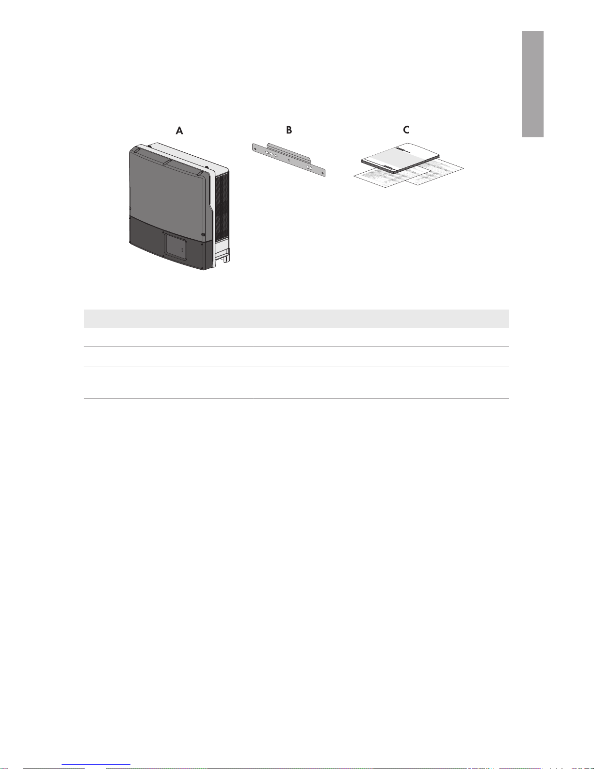
Figure 1 : Components included in the scope of delivery
Position Quantity Designation
A 1 Inverter
B 1 Wall mounting bracket
C 1 Installation manual, production test report, supplementary
sheet with the default settings
3 Scope of Delivery
SMA Solar Technology America LLC
Installation Manual 13STPTL-US-10-IA-xx-17
ENGLISH
4 Product Description
4.1 SunnyTripower
The SunnyTripower is a transformerless PV inverter with two MPP trackers which converts the direct
current of the PV array to grid-compliant three-phase current and feeds it into the utility grid.
No galvanic isolation
• The product is not equipped with a transformer and therefore has no galvanic isolation.
Do not use grounded PV modules with the product. Only ground the mounting frame of
the PV modules. If you connect grounded PV modules to the product, the error message
Insulation resistance > Check generator occurs.
• The AC output/neutral conductor is not bonded to ground inside of the product.
Model
SB X XXXXXTLUS-
SUNNY BOY
S/N
XXXXXXXXXX
Untilityinteractive 1-phase inverter
Made in Germany
SMA Solar Technology AG
www.sma-solar.com
Date of manufactureMM/YYYY
Max. continuous output Power*XXXX W
ac
Reduced output power rating
Operating voltage range (Vac)*
MIN NOMINAL MAX
XXX
XXX
XXX
XXX
XXX
XXX
Operating frequency range (Hz)*
MIN NOMINAL MAX
XX.X XX.X XX.X
Max. vontinuous output current*
XX.X Aac @ XXX VXX.X Aac @ XXX V
Output power factor X
Max. open circuit input voltage*XXX Vdc
Range of input operating DC voltage (MPPT)*
XXX - XXX Cdc @ XXX V
XXX - XXX Cdc @ XXX V
Oper.temp.range*-XXX°Fto+XXX°F(-XX°Cto +XX°C)
ThisunitcontainsaResidualCurrentMonitor,Isolation
MonitorandInterrupter.Thisunitcontainsalisted
PhotovoltaicArc-FaultCircuit-ProtectionofType1
ENCLOSURE TYPE XR (IP54)
*Formoredetailsandfürtighteningtorque,
allowablewiresizeandtypeseethe
InstallationGuide.
Section 1 of 2
Utility interactive inverter
Lis
tet UL 1741 36AN
Utility interactive 1-Phase inverter
TestedTo Comply
With FCC Standards
FORHOMEOROFFICEUSE
CCAN/CSAC22.2No.107.1-1UL1699B
DE34
A
G
H
E
D
F
A
B
C
F
www.sunnyportal.com/register
PIC 001800304600117
RID:37XXA3
D
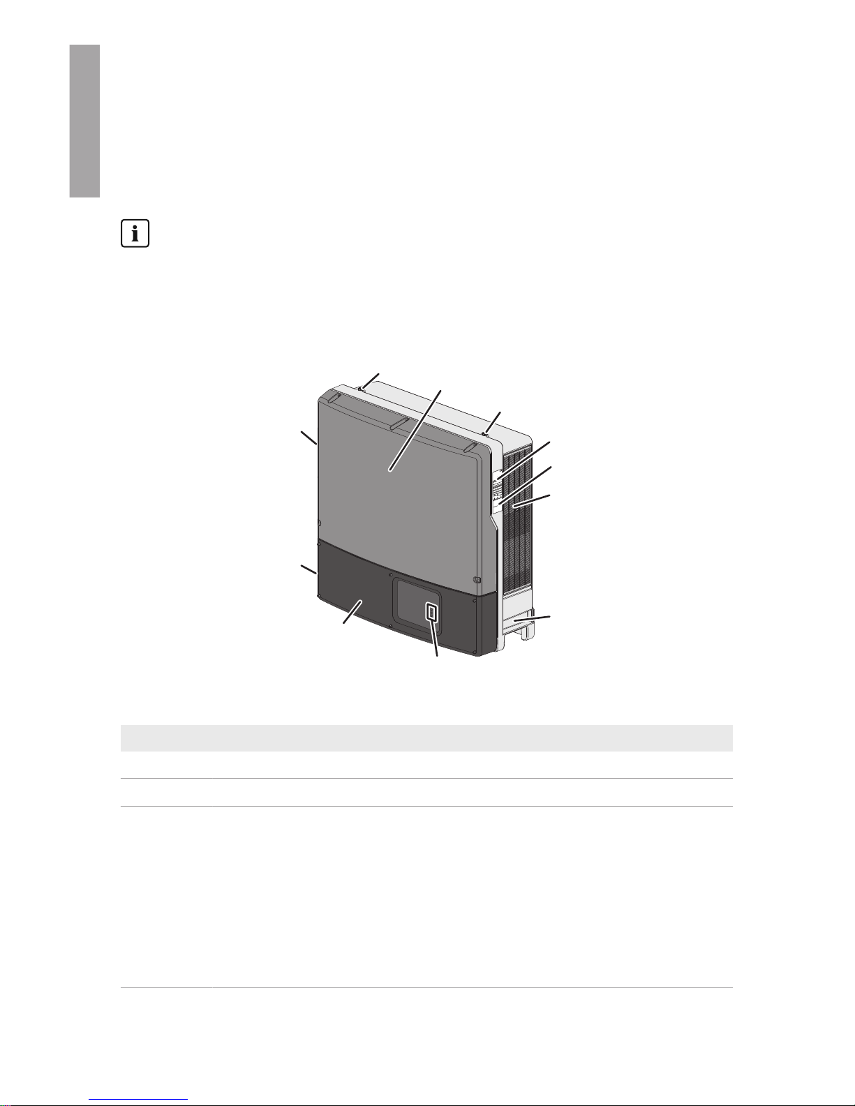
Figure 2 : Design of the SunnyTripower
Position Designation
A Thread for screwing in the eye bolts for transport with a crane
B Upper enclosure lid
C Type label
The type label uniquely identifies the inverter. You will require the information on
the type label to use the product safely and when seeking customer support from
the SMAServiceLine. You will find the following information on the type label:
• Device type (Model)
• Serial number (SerialNo.)
• Date of manufacture
• Device-specific characteristics
4 Product Description
SMA Solar Technology America LLC
Installation ManualSTPTL-US-10-IA-xx-1714
ENGLISH
Position Designation
D Additional label with details for registration in SunnyPortal:
• Internet address of the PV System Setup Assistant
• Identification key (PIC)
• Registration ID (RID)
E Ventilation grid
F Recessed grips
G LEDs
The LEDs indicate the operating state of the inverter:
• Green LED is glowing: operation
• Green LED is flashing: the requirements for the connection to the utility grid
have not been met or the inverter has reduced its output power due to
excessive temperature.
• Red LED is glowing: an error has occurred that must be rectified by a qualified
person (see Section10 "Troubleshooting", page41). You will find the
detailed error message in SunnyPortal or SunnyExplorer.
• Blue LED: no function
H Lower enclosure lid
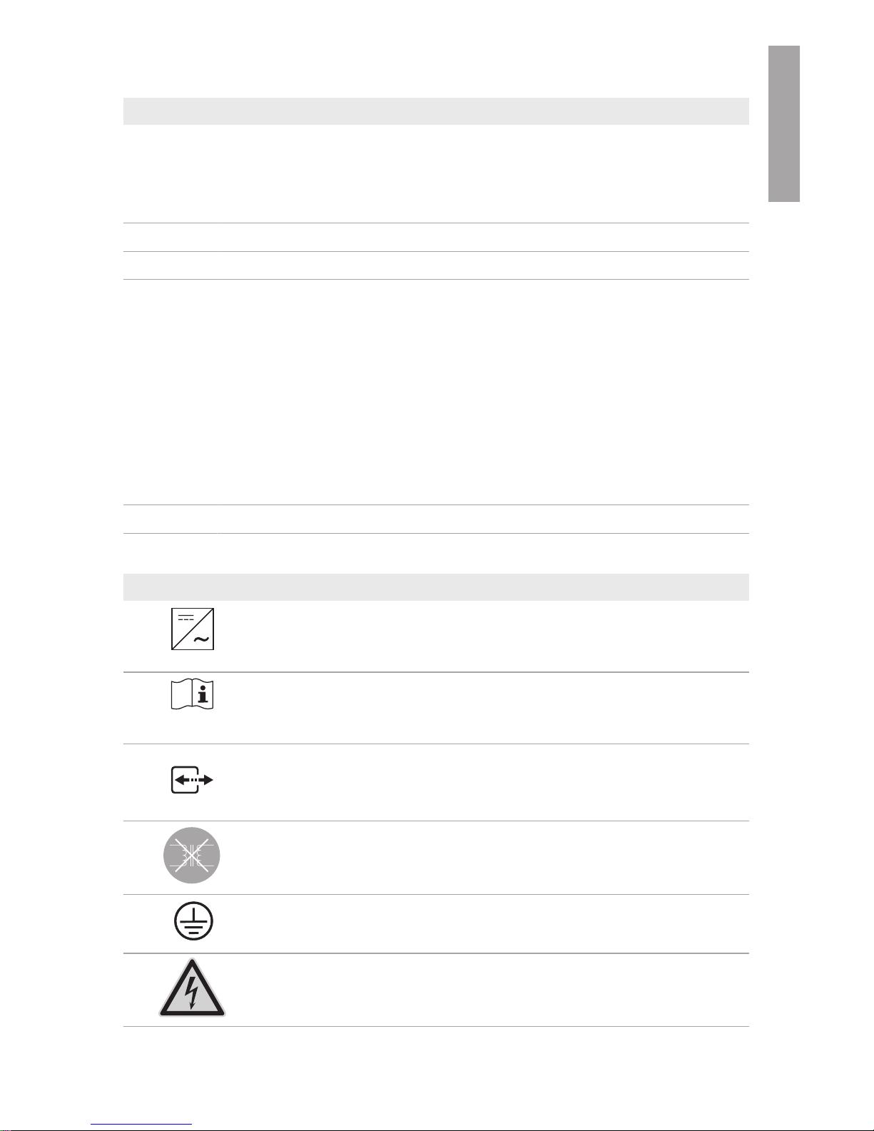
Symbols on the Inverter and on the Type Label
Symbol Explanation
Inverter
This symbol is located next to the green LED which indicates feed-in oper-
ation of the inverter.
Observe the documentation
This symbol is located next to the red LED which indicates a fault or disturbance (see Section10 "Troubleshooting", page41).
Communication
This symbol is located next to the blue LED.
The product does not have a transformer.
Equipment Grounding Terminal
Danger to life due to electric shock
The product operates at high voltages. All work on the product must be
carried out by qualified persons only.
4 Product Description
SMA Solar Technology America LLC
Installation Manual 15STPTL-US-10-IA-xx-17
ENGLISH
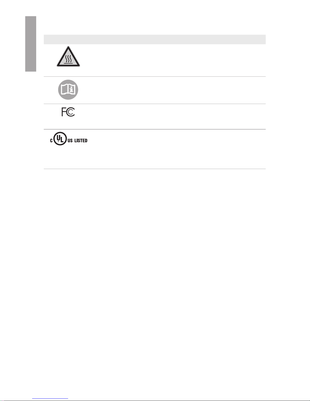
Symbol Explanation
Risk of burns due to hot surfaces
The product can get hot during operation. Avoid contact during opera-
tion. Allow the product to cool down sufficiently before carrying out any
work.
Observe the documentation
Observe all documentation supplied with the product.
FCC designation
The product complies with the requirements of the applicable FCC stan-
dards.
UL certification mark
UL1741 is the standard applied by Underwriters Laboratories to the
product to certify that it meets the requirements of the National Electrical
Code®, the Canadian Electrical Code® CSA C22.1; the IEEE‑929‑2000
and IEEE1547.
4.2 Interfaces and Functions
The inverter can be equipped or retrofitted with the following interfaces and functions:
SMASpeedwire/Webconnect
The inverter is equipped with SMA Speedwire/Webconnect as standard. SMA Speedwire/
Webconnect is a type of communication based on the Ethernet standard. This enables inverteroptimized 10/100Mbit data transmission between Speedwire devices in PV systems and the
software Sunny Explorer. The Webconnect function enables direct data transmission between the
inverters of a small-scale system and the Internet portal SunnyPortal without any additional
communication device and for a maximum of 4 inverters per SunnyPortal system. In large-scale PV
power plants, data transmission to the Internet portal SunnyPortal is carried out via the
SMAClusterController. You can access your SunnyPortal system from any computer with an
Internet connection.
Class 1 wiring methods are to be used for field wiring connection to the terminals of the
communication interface.
RS485 Interface
The inverter can communicate via cables with special SMA communication products via the RS485
interface (information on supported SMAproducts at www.SMA-Solar.com). The RS485 interface
can be retrofitted and can be used in place of the SMASpeedwire/Webconnect interface in the
inverter.
Class 1 wiring methods are to be used for field wiring connection to the terminals of the
communication interface.
Grid Management Services
The inverter is equipped with service functions for grid management.
4 Product Description
SMA Solar Technology America LLC
Installation ManualSTPTL-US-10-IA-xx-1716
ENGLISH

Depending on the requirements of the grid operator, you can activate and configure the functions
(e.g. active power limitation) via operating parameters.
SMAOptiTracGlobalPeak
SMAOptiTracGlobalPeak is an advancement of SMAOptiTrac and allows the operating point of
the inverter to follow the optimal operating point of the PV array (MPP) precisely at all times. In
addition, with the aid of SMAOptiTracGlobalPeak, the inverter detects several maximum power
points in the available operating range, such as may occur particularly with partially shaded
strings. You can activate SMAOptiTracGlobalPeak via the operating parameters (see Section8.5
"Setting SMA OptiTrac Global Peak", page37).
Arc-Fault Circuit Interrupter (AFCI)
In accordance with the National Electrical Code®, Article 690.11, the inverter has a system for arc
fault detection and interruption.
An electric arc with a power of 300W or greater must be interrupted by the AFCI in the time
specified by UL 1699B. A detected electric arc causes the inverter to interrupt feed-in operation: In
order to restart feed-in operation, the feed-in operation must be activated manually. If the
installation conditions allow it, you can deactivate the arc-fault circuit interrupter.
QonDemand 24/7
The inverter can supply reactive power by means of QonDemand24/7 covering the entire unit
circle around the clock (for details on the configuration refer to the Technical Information
"IntegratedPlantControl and QonDemand24/7" at www.SMA-Solar.com).
IntegratedPlantControl
The inverter can display the Q(V) characteristic curve specified by the grid operator by means of
IntegratedPlantControl without measuring on the grid-connection point. The inverter can
automatically compensate equipment installed between the inverter and the grid-connection point
after having activated the function (for information on the system configuration refer to the Technical
Information "IntegratedPlantControl and QonDemand24/7" at www.SMA-Solar.com).
4 Product Description
SMA Solar Technology America LLC
Installation Manual 17STPTL-US-10-IA-xx-17
ENGLISH
5 Mounting
5.1 Requirements for Mounting
Requirements for the mounting location:
Danger to life due to fire or explosion
Despite careful construction, electrical devices can cause fires.
• Do not mount the inverter in areas containing highly flammable materials or gases.
• Do not mount the inverter in a potentially explosive atmosphere.
☐ Do not mount the inverter on a pillar.
☐ Do not install the inverter in a living area.
☐ The inverter must be mounted on a solid surface (e.g. concrete, brickwork, free-standing
constructions).
☐ The inverter can be mounted in a position that is directly exposed to solar irradiation. There is,
however, the possibility that the inverter reduces its power output to avoid overheating due to
high temperatures.
☐ The mounting location must be suitable for the weight and dimensions of the inverter (see
Section14 "Technical Data", page66).
☐ To ensure optimum operation, the ambient temperature should be between -25°C (-13°F) and
60°C (140°F).
☐ Climatic conditions must be met (see Section14 "Technical Data", page66).
☐ The mounting location should be freely and safely accessible at all times without the need for
any auxiliary equipment (such as scaffolding or lifting platforms). Non-fulfillment of these
criteria may restrict servicing.
5 Mounting
SMA Solar Technology America LLC
Installation ManualSTPTL-US-10-IA-xx-1718
ENGLISH
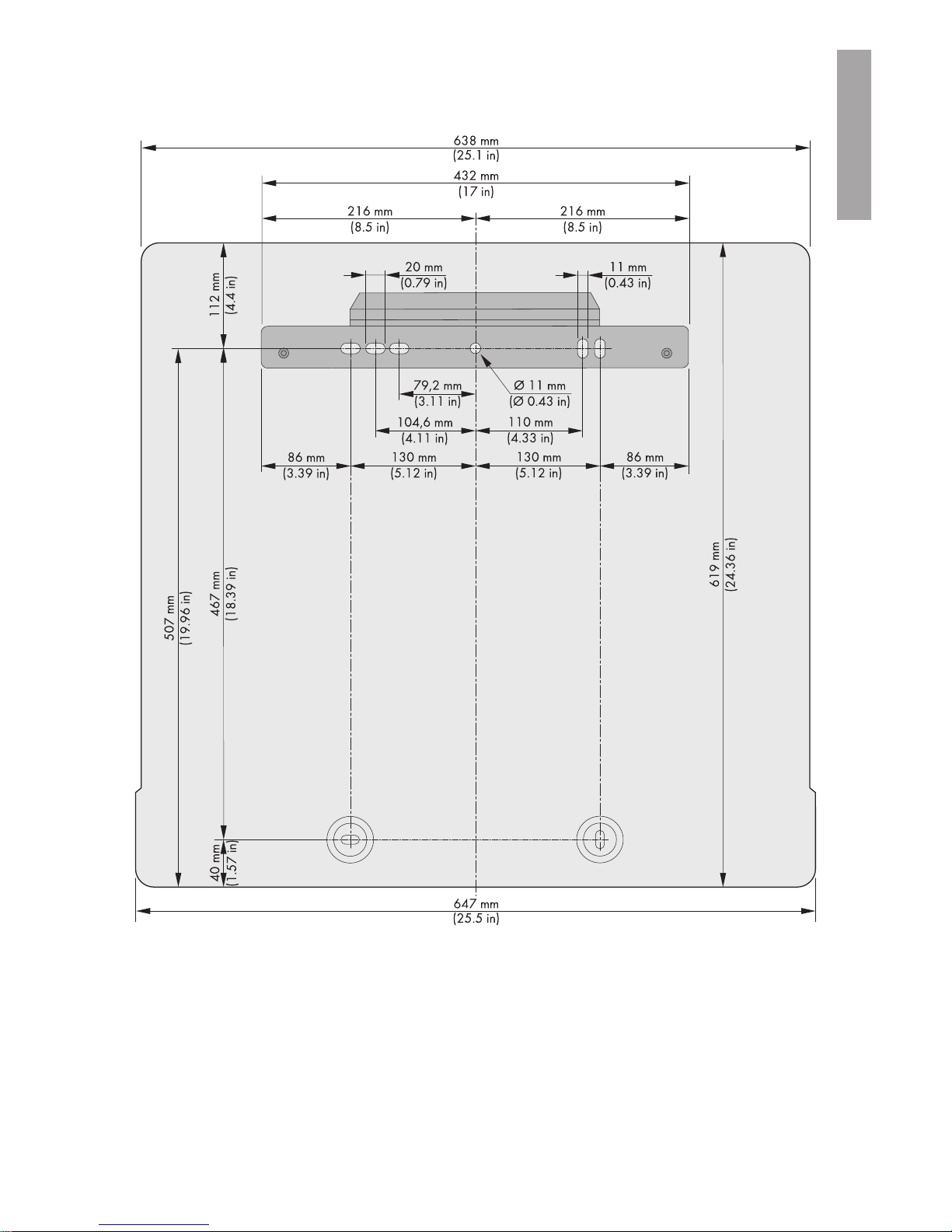
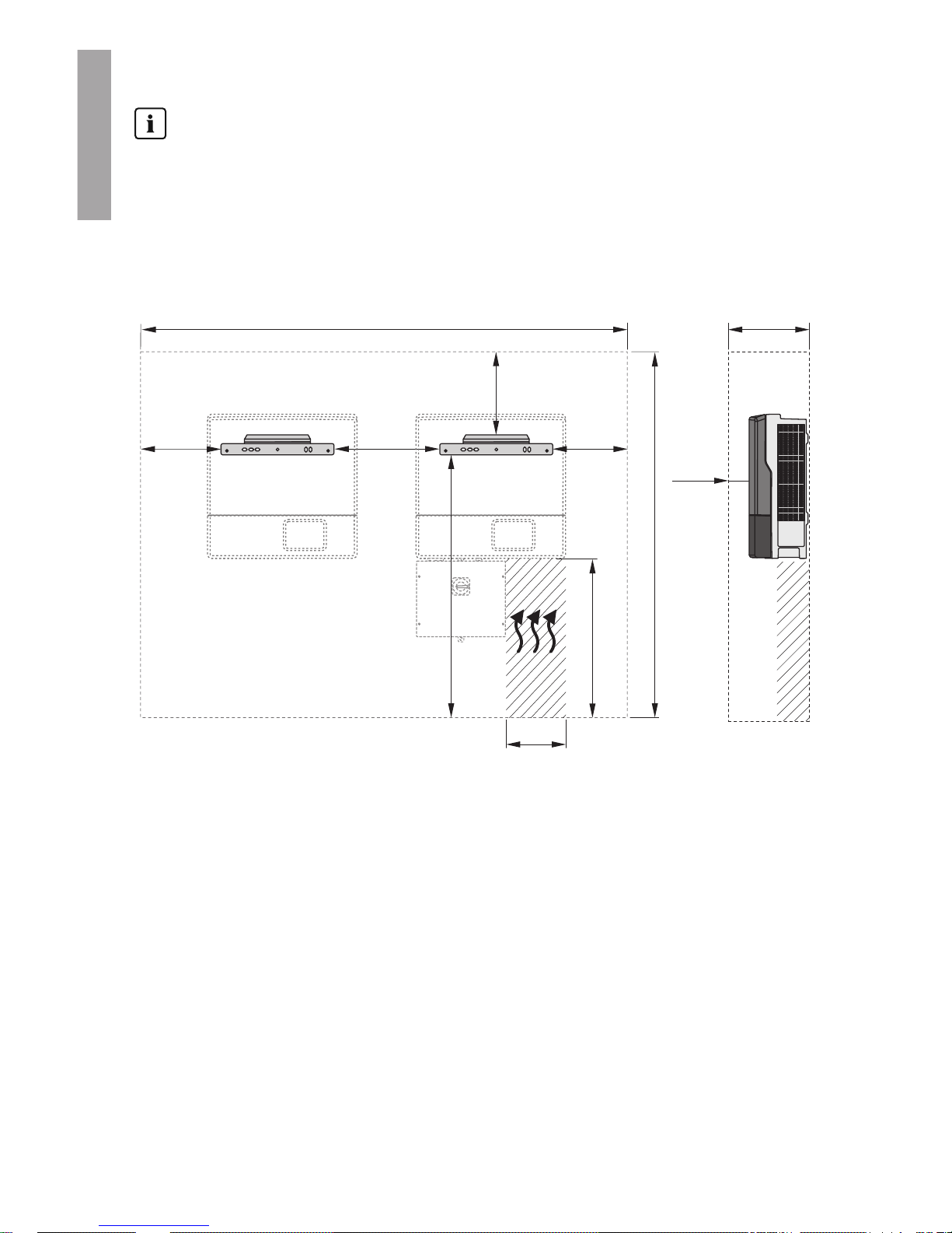
Dimensions for mounting:
Figure 3 : Position of the anchoring points
Recommended clearances:
To guarantee optimal operation and adequate heat dissipation for the inverter, the following
requirements for clearances should be observed. This will prevent the inverter power output from
being reduced due to excessive temperatures. However, smaller clearances are permitted without
causing any risk.
5 Mounting
SMA Solar Technology America LLC
Installation Manual 19STPTL-US-10-IA-xx-17
ENGLISH
Prescribed clearances in accordance with the
National Electrical Code
®
Under certain conditions, the National Electrical Code® specifies greater clearances.
• Ensure that the prescribed clearances in accordance with the National Electrical Code®,
paragraph 110.26 and Canadian Electrical Code® CSA C22.1 are adhered to.
☐ Observe the recommended clearances to walls as well as to other inverters or objects.
☐ Ensure adequate clearance on the right-hand side of the inverter below the fan.
☐ If multiple inverters are mounted in areas with high ambient temperatures, increase the
clearances between the inverters and ensure an adequate fresh-air supply, if possible.
1382 mm
(54.41 in)
2224 mm
(87.56 in)
530 mm
(20.87 in)
50 mm
(1.97 in)
400 mm
(15.45 in)
315 mm
(14.45 in)
415 mm
(16.34 in)
438 mm
(17.24 in)
415 mm
(16.34 in)
940 mm
(37.01 in)
(7.48 in)
190 mm
Figure 4 : Recommended clearances
Permitted and prohibited mounting positions:
☐ The inverter must only be mounted in one of the permitted positions. This will ensure that no
moisture can penetrate the inverter.
☐ The inverter should be mounted in such a way that LED signals can be read without difficulty.
5 Mounting
SMA Solar Technology America LLC
Installation ManualSTPTL-US-10-IA-xx-1720
ENGLISH
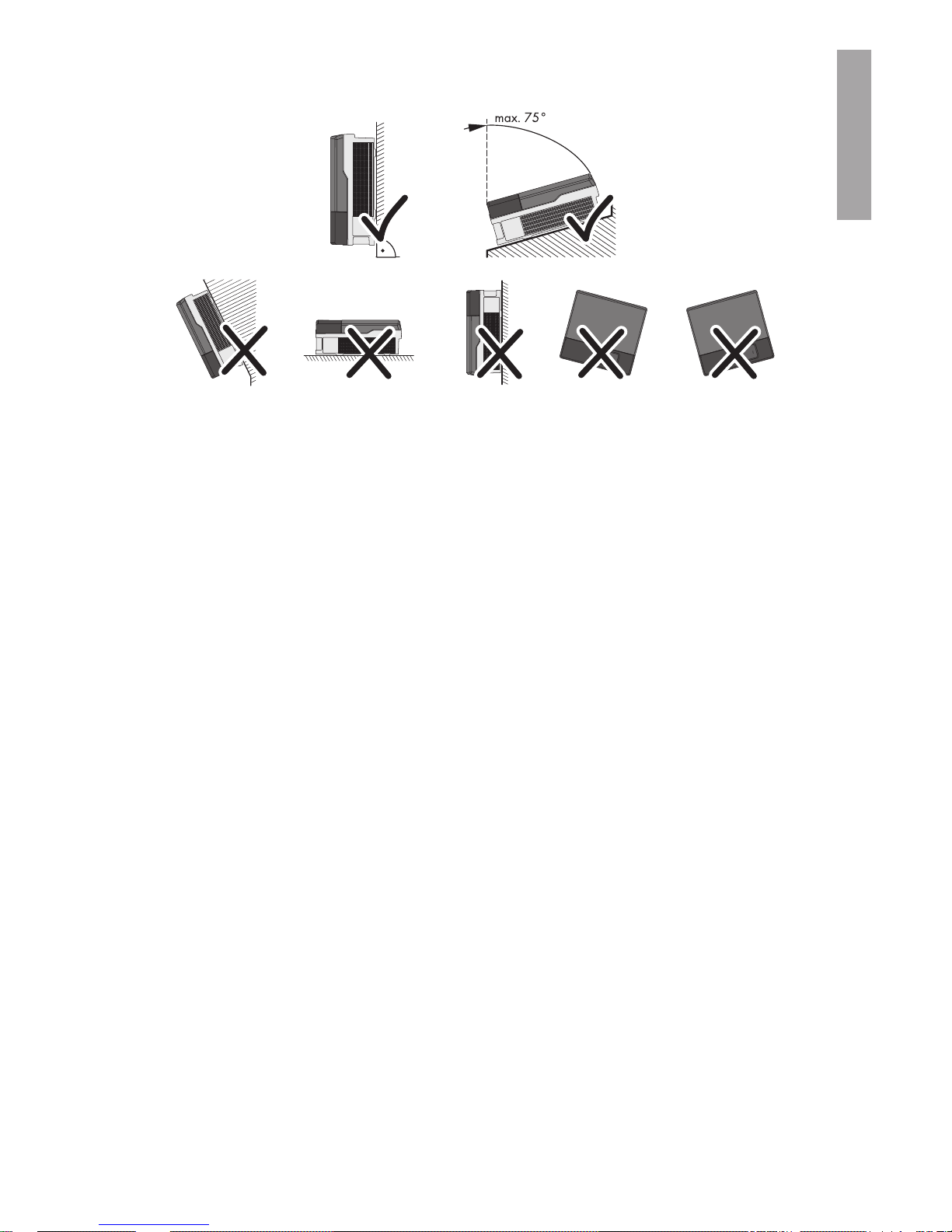
Figure 5 : Permitted and prohibited mounting positions:
5.2 Mounting the Inverter
Additionally required mounting material (not included in the scope of delivery):
☐ At least two screws suitable for the support surface (diameter: 10mm at maximum)
☐ At least two washers that are suitable for the screws (diameter: 30mm (1.8in) at maximum)
☐ If necessary, two screw anchors suitable for the support surface and the screws
☐ For transporting the inverter with a crane: two eye bolts suitable for the weight of the inverter
(size: M10)
☐ To secure the inverter from being lifted off: two screws, washers and screw anchors that are
suitable for the support surface
5 Mounting
SMA Solar Technology America LLC
Installation Manual 21STPTL-US-10-IA-xx-17
ENGLISH
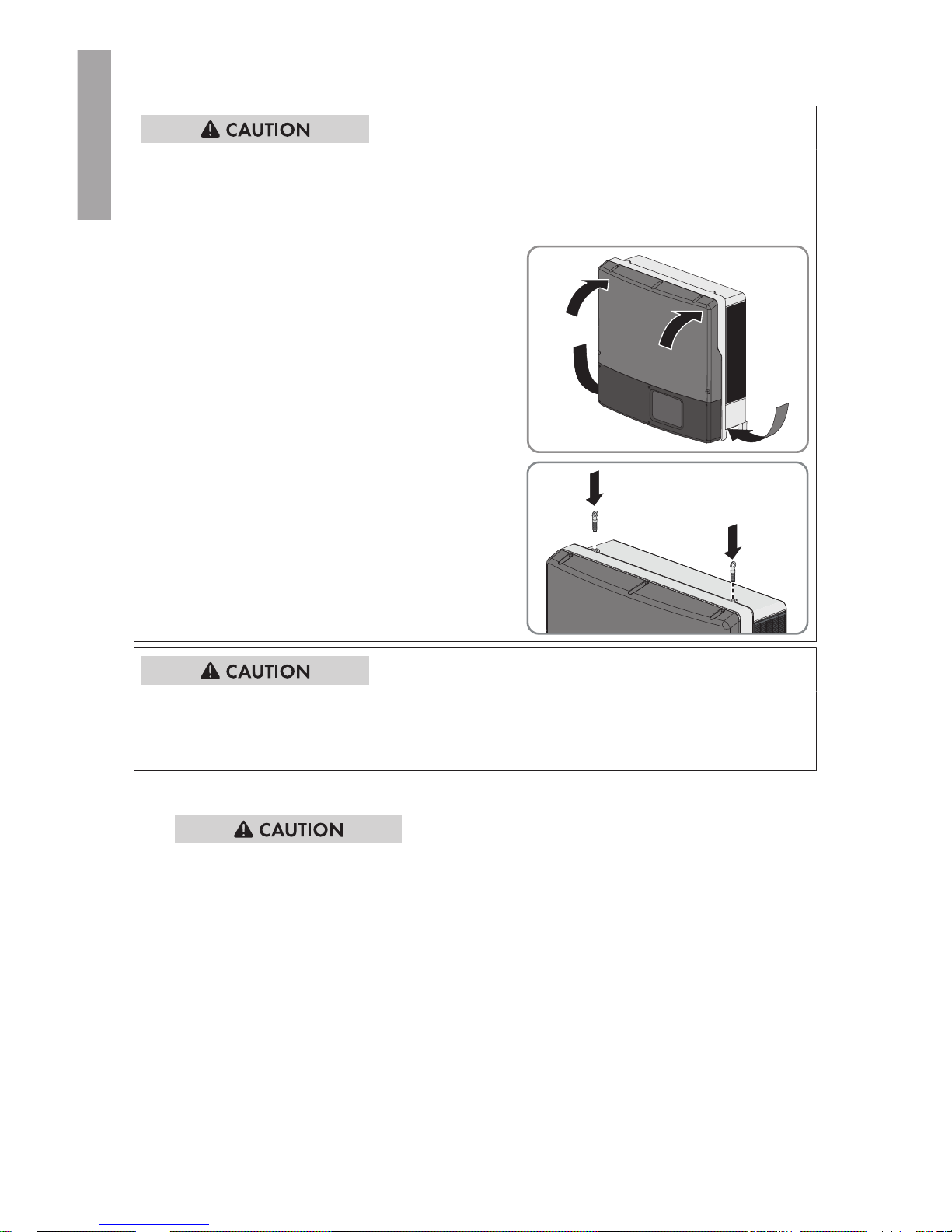
Risk of injury when lifting the inverter, or if it is dropped
The inverter weighs 55kg (121lb). There is risk of injury if the inverter is lifted incorrectly or
dropped while being transported or when attaching it to or removing it from the wall mounting
bracket.
• Carry and lift the inverter in an upright position
with several people without tilting it. With one
hand grasp the recessed grip, and with the
other hand support the top part of the
enclosure. This will prevent the inverter tipping
forward.
• If the inverter is to be transported and lifted
with a crane, remove the filler plugs on the top
of the inverter and screw the eye bolts into the
threads.
Risk of burns due to hot enclosure parts
Some parts of the enclosure can get hot during operation.
• Mount the inverter in such a way that it cannot be touched inadvertently during operation.
Procedure:
1.
Risk of injury due to damaged cables
There may be power cables or other supply lines (e.g. gas or water) routed in the wall.
• Ensure that no lines are laid in the wall which could be damaged when drilling holes.
2. Align the wall mounting bracket horizontally on the wall and use it to mark the position of the
drill holes. Use at least one hole on the right-hand and left-hand side in the wall mounting
bracket.
3. If the inverter is to be secured from being lifted off of the wall mounting bracket, mark the
position of the drill holes for the screw that attaches the inverter to the wall mounting bracket.
Observe the dimensions of the two anchoring points at the bottom of the inverter rear panel.
4. Set the wall mounting bracket aside and drill the marked holes.
5. Insert screw anchors into the drill holes if the support surface requires them.
6. Secure the wall mounting bracket horizontally using screws and washers.
5 Mounting
SMA Solar Technology America LLC
Installation ManualSTPTL-US-10-IA-xx-1722
ENGLISH
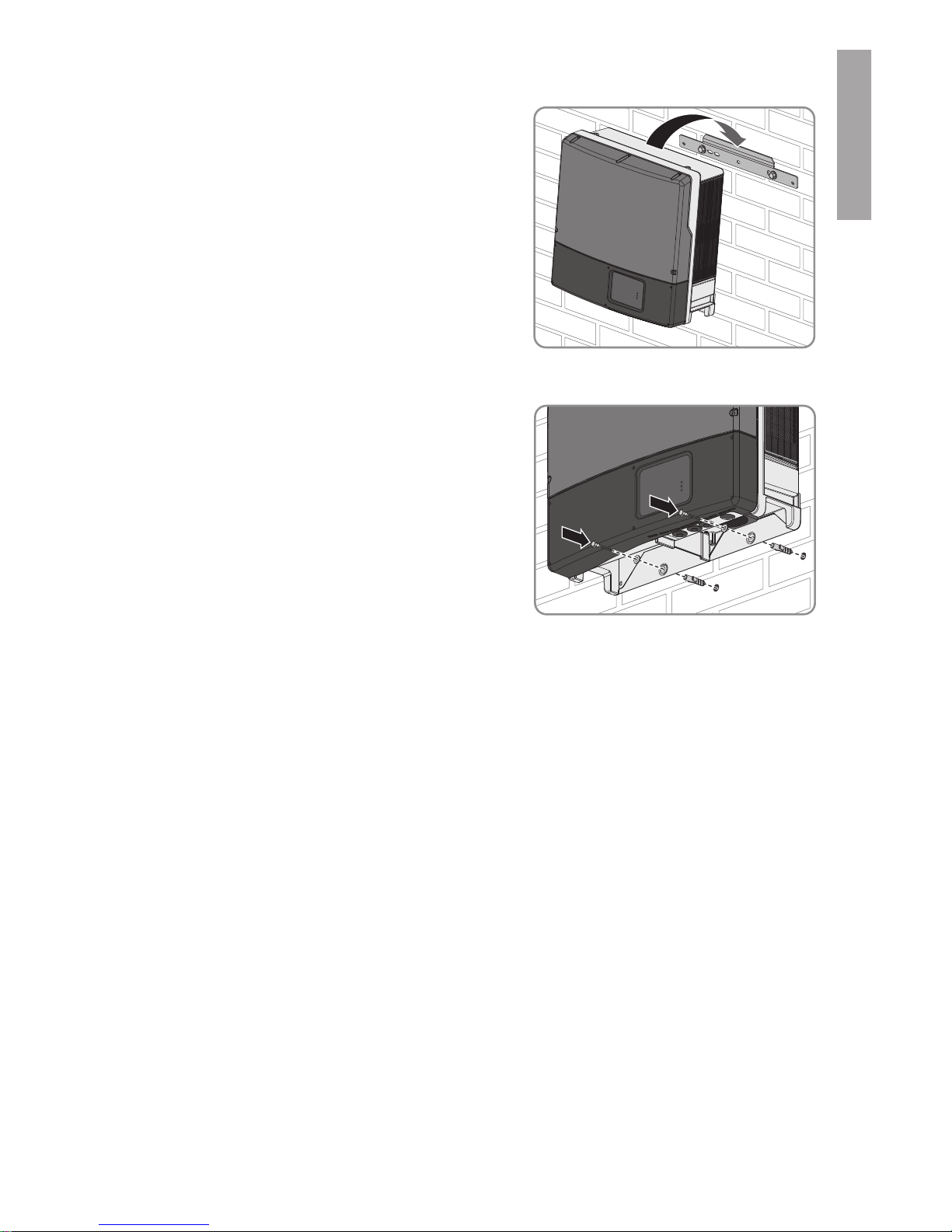
7. Hook the inverter into the wall mounting bracket.
8. If the inverter has been transported with a crane, remove the eye bolts from the threads on the
top of the inverter and reinsert the filler plugs.
9. In order to secure the inverter from being lifted
off the wall accidentally, attach it to the wall with
suitable mounting material. Use both of the
lower drill holes on the rear panel of the inverter.
10. Ensure that the inverter is securely in place.
5 Mounting
SMA Solar Technology America LLC
Installation Manual 23STPTL-US-10-IA-xx-17
ENGLISH
6 Electrical Connection
6.1 Safety during Electrical Connection
Danger to life due to high voltages of the PV array
When exposed to sunlight, the PV array generates dangerous DC voltage which is present in the
DC conductors and the live components of the inverter. Touching the DC conductors or the live
components can lead to lethal electric shocks. If you disconnect the DC connectors from the
inverter under load, an electric arc may occur leading to electric shock and burns.
• Do not touch non-insulated cable ends.
• Do not touch the DC conductors.
• Do not touch any live components of the inverter.
• Have the inverter mounted, installed and commissioned only by qualified persons with the
appropriate skills.
• If an error occurs, have it rectified by qualified persons only.
• Prior to performing any work on the inverter, disconnect it from all voltage sources as
described in this document (see Section9 "Disconnecting the Inverter from Voltage Sources",
page39).
Risk of fire
• To reduce the risk of fire, connect only to a circuit provided with 50A maximum branchcircuit overcurrent protection in accordance with the National Electrical Code® (NE, ANSI/
NFPA 70).
Damage to seals on the enclosure lids in subfreezing conditions
If you open the upper and lower enclosure lids when temperatures are below freezing, the
enclosure seals can be damaged. This can lead to moisture entering the inverter.
• Do not open the inverter at ambient temperatures lower than -5°C (23°F).
• If a layer of ice has formed on the seal of the lid when temperatures are below freezing,
remove it prior to opening the enclosure lids of the inverter (e.g. by melting the ice with
warm air). Observe the applicable safety regulations.
Damage to the inverter due to electrostatic discharge
Touching electronic components can cause damage to or destroy the inverter through
electrostatic discharge.
• Ground yourself before touching any component.
6 Electrical Connection
SMA Solar Technology America LLC
Installation ManualSTPTL-US-10-IA-xx-1724
ENGLISH
Damage to the inverter due to moisture ingress during electrical installation
• Never open the inverter when it is raining or snowing, or the humidity is over 95%.
• For attaching the conduits to the enclosure, only use UL-listed rain-tight conduit fittings or ULlisted conduit fittings for wet locations complying with UL514B.
• Seal all unused openings tightly.
Ground faults, unreliable and highly resistive connections due to
Wire Nuts
®
Potential damage to or failure of the inverter.
• Do not use Wire Nuts®.
Electrical installations
All electrical installations must be carried out in accordance with the local standards and the
National Electrical Code® ANSI/NFPA 70 or the Canadian Electrical Code® CSA C22.1.
• Before connecting the inverter to the utility grid, contact your local grid operator. The
electrical connection of the inverter must be carried out by qualified persons only.
• Ensure that no cables used for electrical connection are damaged.
6.2 Overview of the Connection Area
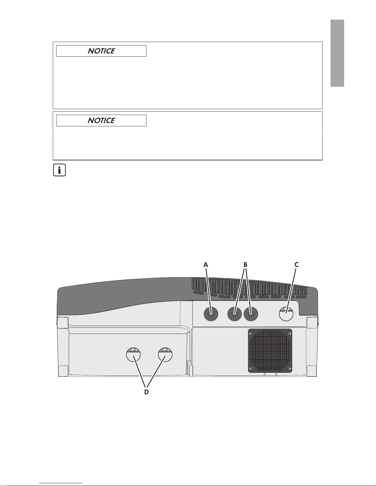
6.2.1 View from Below
Figure 6 : Enclosure openings at the bottom of the inverter
6 Electrical Connection
SMA Solar Technology America LLC
Installation Manual 25STPTL-US-10-IA-xx-17
ENGLISH
Position Designation
A Enclosure opening with filler plug for communication connection
(diameter: 27.8mm to 28.0mm (1.09in to 1.10in))
B Enclosure opening with filler plug for Ethernet connection
(diameter: 27.8mm to 28.0mm (1.09in to 1.10in))
C Enclosure opening for AC connection
(diameter: 34.5mm to 34.7mm (1.36in to 1.37in))
D Enclosure openings for DC connection
(diameter: 34.5mm to 34.7mm (1.36in to 1.37in))
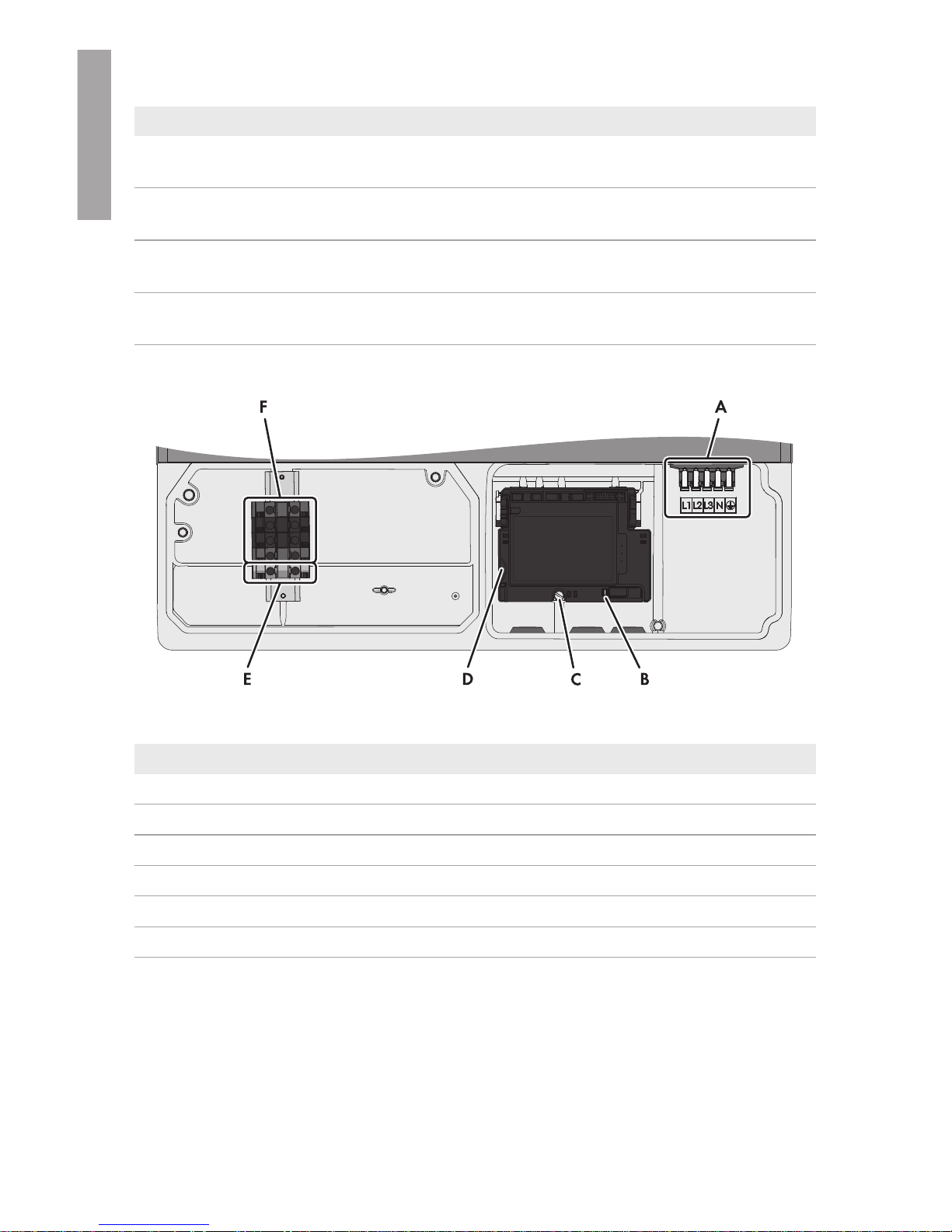
6.2.2 Interior View
Figure 7 : Connection areas in the interior of the inverter
Position Designation
A Connecting terminal plate for AC connection
B Switch for changing the language to English for service purposes
C Screw to release and attach the communication board
D Slot for the SD memory card, for service purposes only
E Terminal for equipment grounding and grounding electrode conductor
F Connecting terminal plate for DC connection
6.3 AC Connection
6.3.1 Requirements for the AC Connection
Additionally required material (not included in the scope of delivery):
☐ 1 metal conduit: 25.4mm (1in)
☐ 1 UL-listed rain-tight conduit fitting for wet locations: 25.4mm (1in)
6 Electrical Connection
SMA Solar Technology America LLC
Installation ManualSTPTL-US-10-IA-xx-1726
ENGLISH
Cable requirements:
☐ The AC cable must be approved for temperatures of over +90°C (+194°F).
☐ The AC cable must be designed in accordance with the local installation requirements.
☐ The AC cable must be made of solid wire or stranded wires.
☐ Conductor cross-section: 10mm² to 6mm² (8AWG to 6AWG)
☐ Conductor type: copper wire
☐ The maximum cable length subject to conductor cross-section must be observed.
Load-break switch and cable protection:
Damage to the inverter due to the use of screw-type fuses as load-break switch
Screw-type fuses are not load-break switches.
• Do not use screw-type fuses as load-break switches.
• Use a load-break switch or a circuit breaker for load disconnection.
☐ In PV systems with multiple inverters, protect each inverter with a separate three-phase circuit
breaker. Observe the maximum permissible fuse protection (see Section14 "Technical Data",
page66). This will prevent residual voltage from being present at the corresponding cable
after disconnection.
☐ The load-break switch or circuit breaker must be listed (seeNational Electrical Code®, ANSI/
NFPA 70)
☐ Loads installed between the inverter and the circuit breaker must be fused separately.
☐ The overcurrent protection for the AC output circuit is to be provided by others.
Compatible grid configurations:
Device 480V / 277V WYE 480VDelta
STP 12000TL-US-10 Yes No
STP 15000TL-US-10 Yes No
STP 20000TL-US-10 Yes No
STP 24000TL-US-10 Yes No
STP 30000TL-US-10* Yes Yes
* A neutral conductor connection is necessary for the 480V / 277V WYE. A neutral conductor
connection is not necessary for the 480V Delta.
6.3.2 Connecting the Inverter to the Utility Grid
Requirements:
☐ All electrical installations must be carried out in accordance with the local standards and the
National Electrical Code® ANSI/NFPA 70 or the Canadian Electrical Code® CSA C22.1.
☐ The AC and DC electric circuits are isolated from the enclosure. If required by section 250 of
the National Electrical Code®, ANSI/NFPA 70, the installer is responsible for grounding the
system.
6 Electrical Connection
SMA Solar Technology America LLC
Installation Manual 27STPTL-US-10-IA-xx-17
ENGLISH
☐ The connection requirements of the grid operator must be met.
☐ The grid voltage must be within the permissible range. The exact operating range of the
inverter is specified in the operating parameters.
Procedure:
1.
Danger to life due to electric shock
• Ensure that the three-pole circuit breaker is switched off and cannot be reconnected.
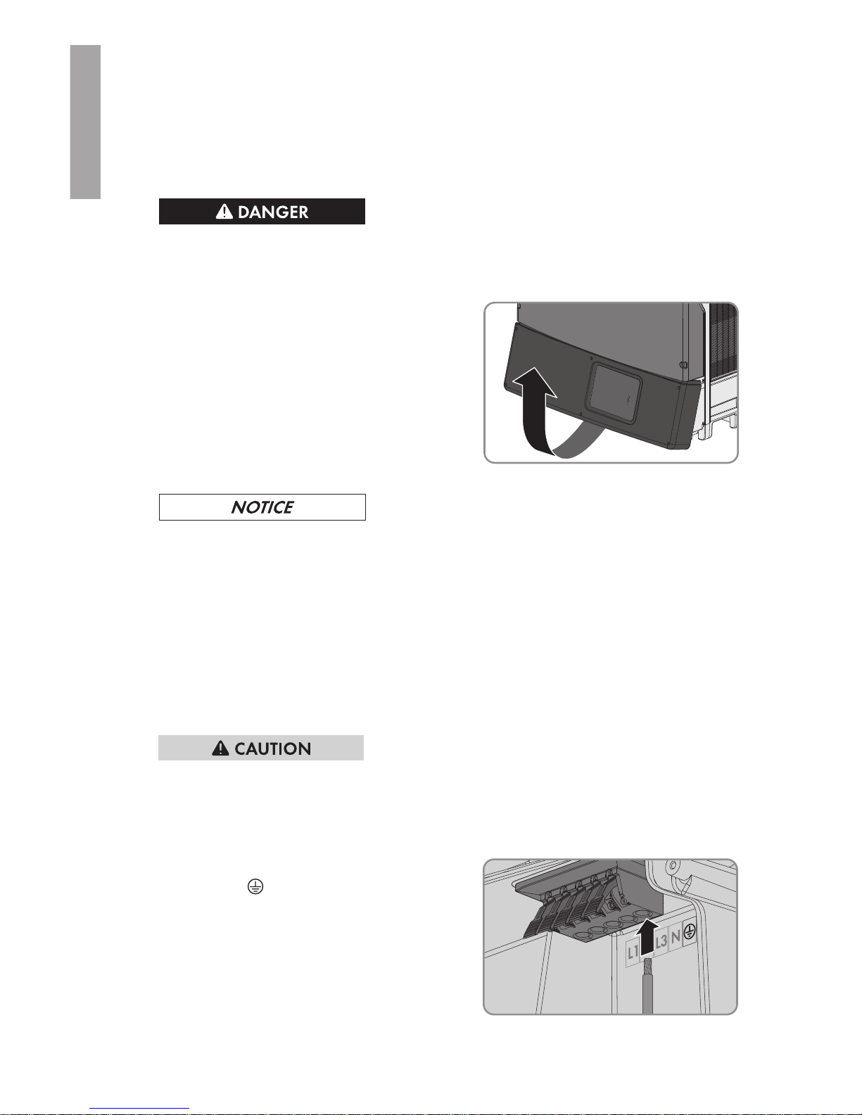
2. Release all screws of the lower enclosure lid using an Allen key (AF3).
3. Lift and remove the lower enclosure lid from
below.
4. Remove the adhesive tape from the enclosure opening for the AC connection.
5.
Damage to the inverter due to moisture and dust intrusion
Electronic components in the inverter can be destroyed or damaged as a result of dust or
moisture intrusion.
• Do not enlarge the enclosure opening.
6. Insert the conduit fitting into the opening and tighten from the inside using the counter nut.
7. Attach the conduit to the enclosure opening.
8. Insert the AC cable through the conduit into the inverter.
9. Strip the cable insulation by 12mm to 13mm (0.5 in).
10. Open all locking levers of the connecting terminal plate right up to the stop.
11.
Risk of fire if two conductors are connected to one terminal
If you connect two conductors to a terminal, a fire can occur due to a bad electrical
connection.
• Never connect more than one conductor per terminal.
12. Connect the equipment grounding conductor to
the terminal
.
6 Electrical Connection
SMA Solar Technology America LLC
Installation ManualSTPTL-US-10-IA-xx-1728
ENGLISH
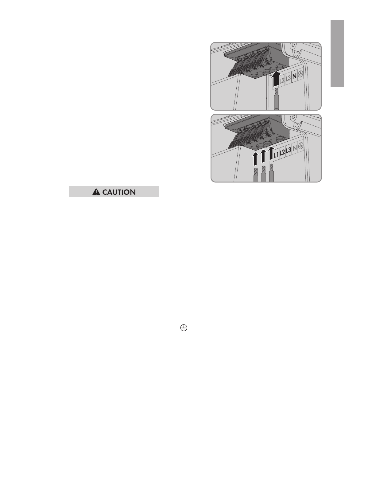
13. Depending on the grid configuration, connect
the neutral conductor to connecting terminal
plate N (see Section6.3.1 "Requirements for the
AC Connection", page26).
14. Connect the conductors L1, L2 and L3 to the
terminals L1, L2 and L3 according to the label.
Ensure that the assignment is correct.
15.
Danger of crushing when locking levers snap shut
The locking levers close by snapping down fast and hard.
• Press the locking levers of the connecting terminal plate for the AC cable down with your
thumb only. Do not grip the entire connecting terminal plate for the AC cable between
finger and thumb and keep fingers out from under the locking levers.
16. Ensure that the correct conductors are assigned to all the terminals.
17. Ensure that all locking levers of the connecting terminal plate are closed and all conductors
are tightly connected.
6.3.3 Connecting Additional Grounding
The inverter is equipped with a grounding terminal with two connection points on the DC side for
additional grounding (e.g. use of a grounding electrode).
The grounding terminal is yellow/green and identified as follows:
• Equipment grounding terminal: symbol
• Grounding electrode conductor: labeling GEC
Cable requirements:
☐ The cable must be designed in accordance with the local installation requirements and for
temperatures of over +90°C (+194°F).
☐ Cable type: copper wire
☐ Conductor cross-section: 10mm² to 35mm² (8AWG to 2AWG)
Requirement:
☐ The conduits must be correctly connected to the inverter.
6 Electrical Connection
SMA Solar Technology America LLC
Installation Manual 29STPTL-US-10-IA-xx-17
ENGLISH
Procedure:
1.
Danger to life due to electric shock
• Disconnect the inverter from all voltage sources (see Section9, page39).
2. If the protective cover is mounted, loosen the screws of the DC protective cover using an Allen
key (AF 3) and remove the DC protective cover.
3. Lead the equipment grounding conductor or the cable of the grounding electrode through the
installed conduit into the inside of the inverter.
4. Strip the equipment grounding conductor or the cable of the grounding electrode by 18mm
(0.71in).
5. Connect the equipment grounding conductor to the connection point with the symbol
and tighten with a screwdriver (blade width: 6mm (0.24in)) (torque: 5.8Nm (51in-lb)).
6. Connect the grounding electrode cable to the connection point GEC and tighten with a
screwdriver (blade width: 6mm (0.24in)) (torque: 5.8Nm (51in-lb)).
7. Make sure the equipment grounding conductor or the grounding electrode cable is firmly in
place.
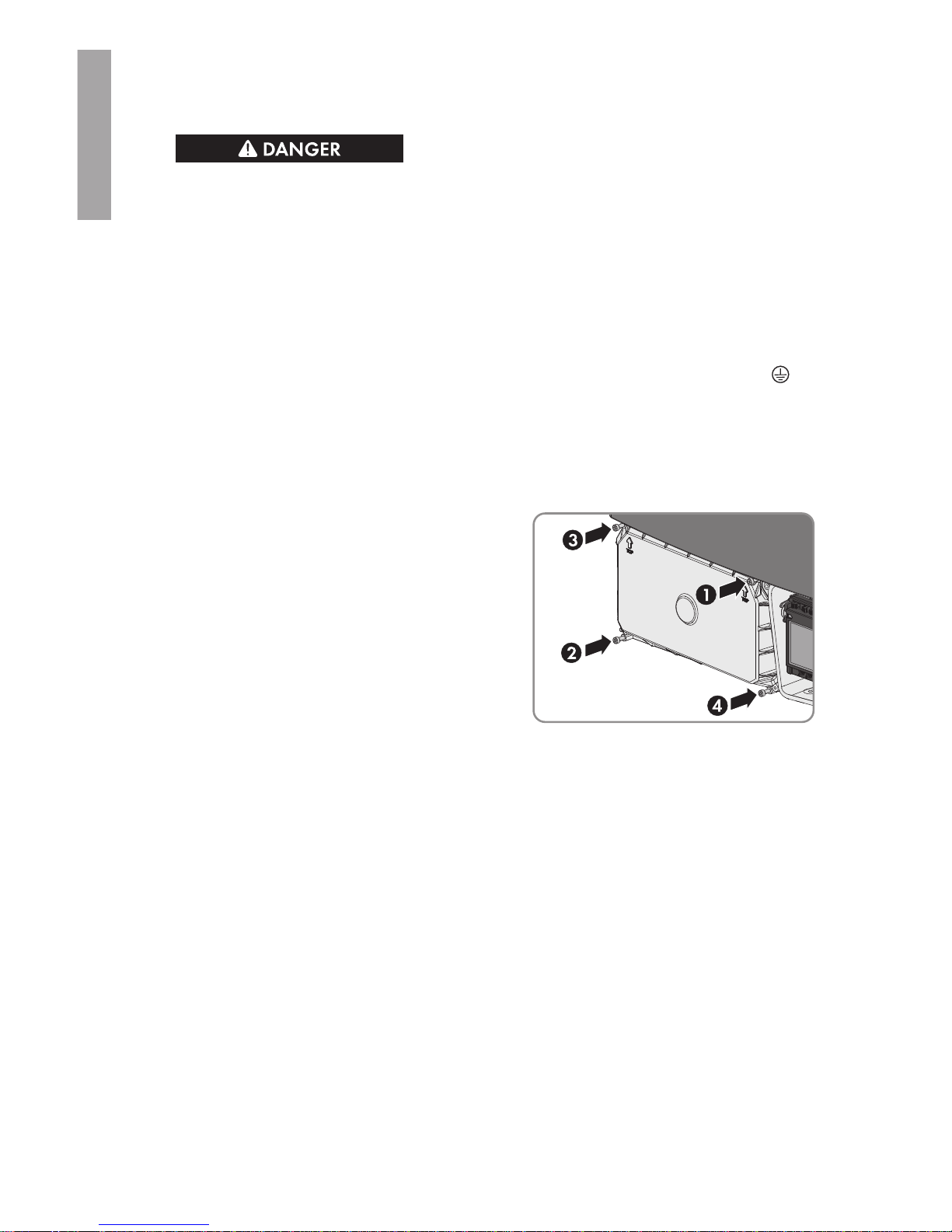
8. Reattach the DC protective cover. Tighten all
four screws with an Allen key (AF3) in the order
1 to 4 (torque: 3.5Nm (31in-lb)).
6.4 DC Connection
6.4.1 Requirements for the DC Connection
Requirements for the PV modules per input:
☐ All PV modules must be of the same type.
☐ All PV modules must be aligned and tilted identically.
☐ On the coldest day based on statistical records, the open-circuit voltage of the PV array must
never exceed the maximum input voltage of the inverter.
☐ The same number of series-connected PV modules must be connected to each string.
☐ The thresholds for the input voltage and the input current of the inverter must be adhered to
(see Section14 "Technical Data", page66).
☐ The maximum input current per string must be maintained (see Section14 "Technical Data",
page66).
Additionally required material (not included in the scope of delivery):
☐ Depending on the number of strings, one or two conduits made of metal: 25.4mm (1in)
6 Electrical Connection
SMA Solar Technology America LLC
Installation ManualSTPTL-US-10-IA-xx-1730
ENGLISH
 Loading...