

SMA SUNNY BOY 3000TL, SUNNY BOY 4000TL, SUNNY BOY 6000TL, SUNNY BOY 3600TL, SUNNY BOY 5000TL Service Manual
...
ServiceManual
SUNNY BOY 3000TL/ 3600TL/ 4000TL/ 5000TL/
6000TL
SB30-60TL-21-SG-en-11 | Version 1.1
AMERICAN ENGLISH

Legal Provisions
SMA Solar Technology AG
Legal Provisions
The information contained in these documents is property of SMA Solar Technology AG. Any
publication, whether in whole or in part, requires prior written approval by SMA Solar Technology
AG. Internal reproduction used solely for the purpose of product evaluation or other proper use is
allowed and does not require prior approval.
SMA Warranty
You can download the current warranty conditions from the Internet at www.SMA-Solar.com.
Trademarks
All trademarks are recognized, even if not explicitly identified as such. A lack of identification does
not mean that a product or symbol is not trademarked.
The BLUETOOTH® word mark and logos are registered trademarks of BluetoothSIG,Inc. and any
use of these marks by SMASolarTechnologyAG is under license.
Modbus® is a registered trademark of Schneider Electric and is licensed by the Modbus
Organization, Inc.
QR Code is a registered trademark of DENSO WAVE INCORPORATED.
Phillips® and Pozidriv® are registered trademarks of Phillips Screw Company.
Torx® is a registered trademark of Acument Global Technologies, Inc.
SMA Solar Technology AG
Sonnenallee 1
34266 Niestetal
Germany
Tel. +49 561 9522-0
Fax +49 561 9522-100
www.SMA.de
E-mail: info@SMA.de
© 2004 to 2014 SMA Solar Technology AG. All rights reserved.
Service ManualSB30-60TL-21-SG-en-112

SMA Solar Technology AG
Table of Contents
Table of Contents
1 Information on this Document ................................................. 4
1.1 Validity................................................................................................ 4
1.2 Target Group...................................................................................... 4
1.3 Symbols .............................................................................................. 4
1.4 Nomenclature..................................................................................... 5
2 Safety......................................................................................... 6
2.1 Safety Information.............................................................................. 6
2.2 Disconnecting the Inverter from Voltage Sources ............................ 7
3 Cleaning the Inverter................................................................ 9
4 Troubleshooting ........................................................................ 10
4.1 LED Signals......................................................................................... 10
4.2 Event Messages ................................................................................. 10
4.3 Error Messages .................................................................................. 11
5 Checking the PV System for Ground Faults............................ 19
6 Checking the Function of the Varistors.................................... 22
7 Replacing the Varistors ............................................................ 24
8 Recommissioning the Inverter.................................................. 25
9 Decommissioning the Inverter ................................................. 27
10 Spare Parts................................................................................ 29
11 Contact....................................................................................... 30
Service Manual 3SB30-60TL-21-SG-en-11
1 Information on this Document
SMA Solar Technology AG
1 Information on this Document
1.1 Validity
This document describes how to rectify certain errors and how to replace defective components.
This document supplements the documents that are enclosed with each product and does not
replace any locally applicable standards or directives. Read and observe all documents supplied
with the product.
This document is valid for the following device types:
• SB 3000TL-21 (Sunny Boy 3000TL)
• SB 3600TL-21 (Sunny Boy 3600TL)
• SB 4000TL-21 (Sunny Boy 4000TL)
• SB 5000TL-21 (Sunny Boy 5000TL)
• SB 6000TL-21 (Sunny Boy 6000TL)
1.2 Target Group
The tasks described in this document must only be performed by qualified persons. Qualified
persons must have the following skills:
• Knowledge of how an inverter works and is operated
• Training in how to deal with the dangers and risks associated with installing and using
electrical devices and installations
• Training in the installation and commissioning of electrical devices and installations
• Knowledge of the applicable standards and directives
• Knowledge of and compliance with this document and all safety information
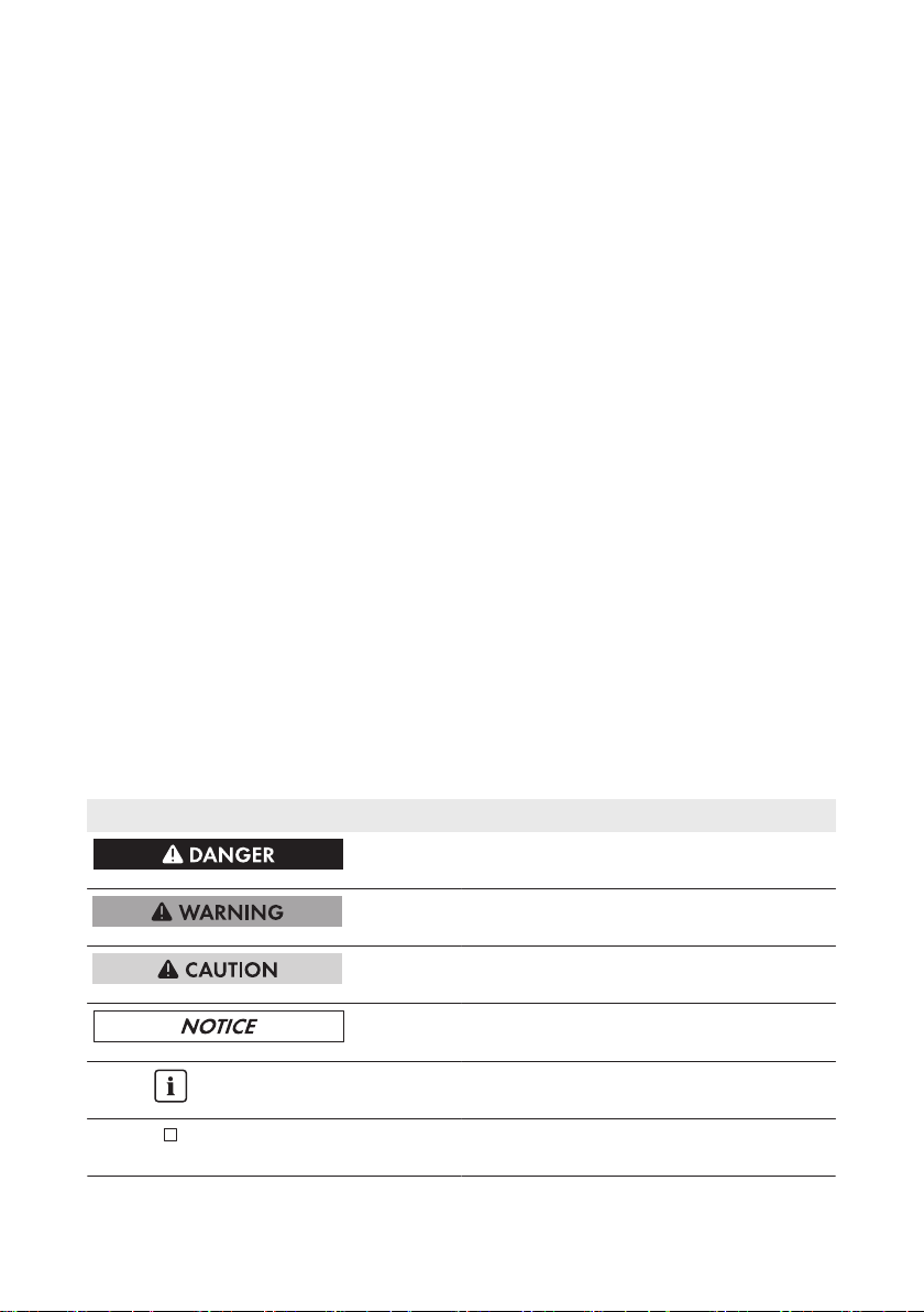
1.3 Symbols
Symbol Explanation
Indicates a hazardous situation which, if not
avoided, will result in death or serious injury
Indicates a hazardous situation which, if not
avoided, can result in death or serious injury
Indicates a hazardous situation which, if not
avoided, can result in minor or moderate injury
Indicates a situation which, if not avoided, can
result in property damage
Information that is important for a specific topic
or goal, but is not safety-relevant
Indicates a requirement for meeting a specific
goal
Service ManualSB30-60TL-21-SG-en-114
SMA Solar Technology AG
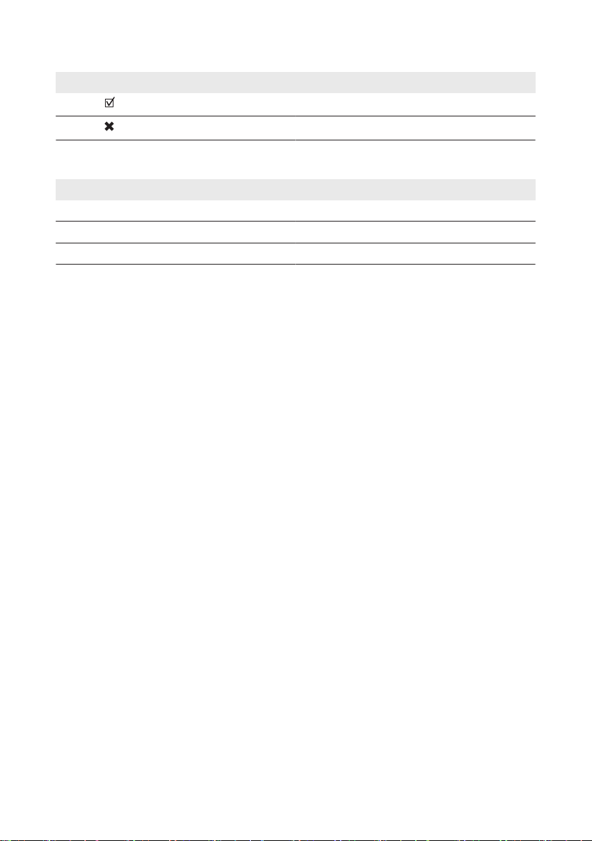
Symbol Explanation
Desired result
A problem that might occur
1 Information on this Document
1.4 Nomenclature
Complete designation Designation in this document
Sunny Boy Inverter, product
Electronic Solar Switch ESS
SMA BLUETOOTH Wireless Technology BLUETOOTH
Service Manual 5SB30-60TL-21-SG-en-11
2 Safety
SMA Solar Technology AG
2 Safety
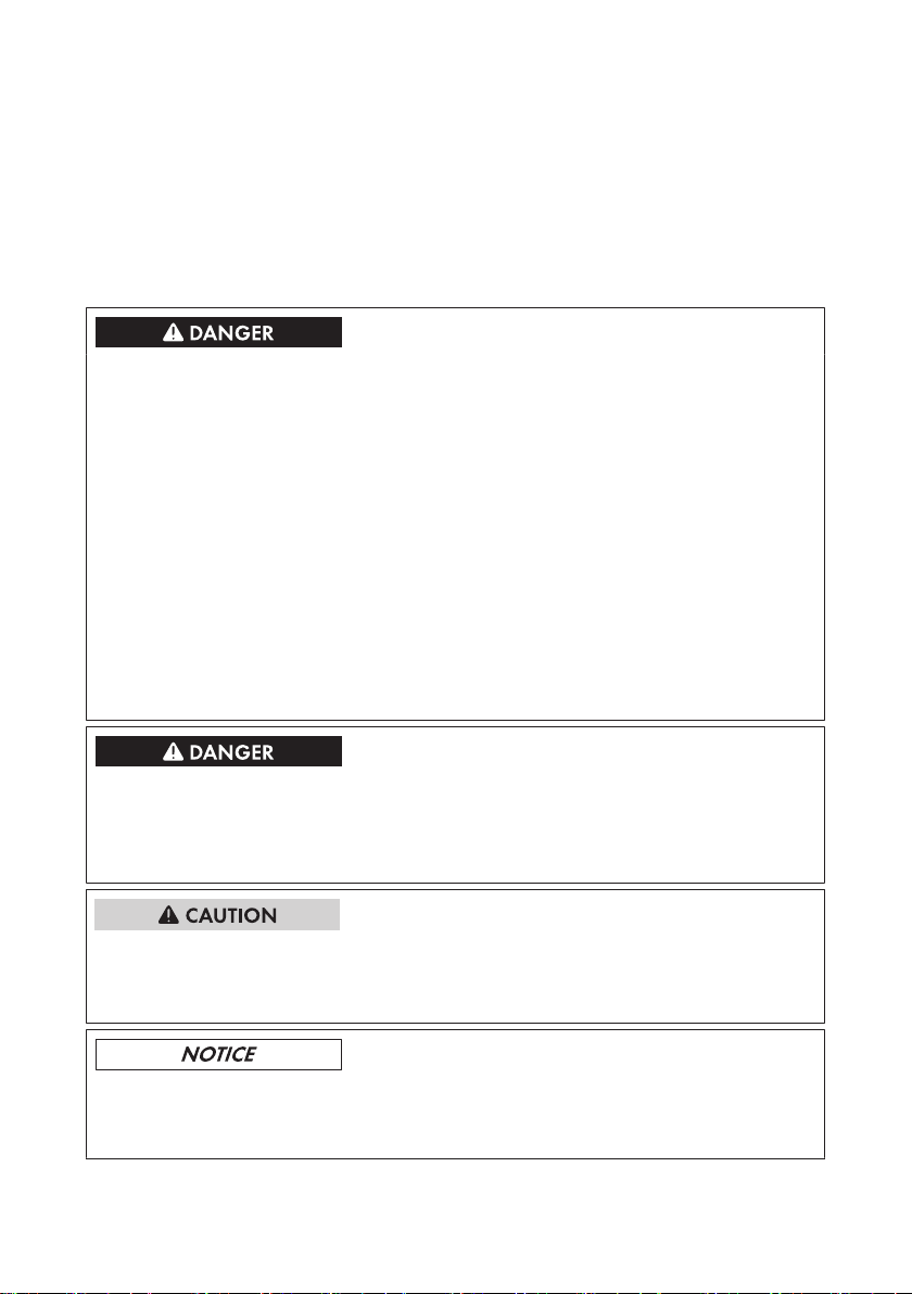
2.1 Safety Information
This section contains safety information that must be observed at all times when working on or with
the product.
To prevent personal injury and property damage and to ensure long-term operation of the product,
read this section carefully and observe all safety information at all times.
Danger to life due to high voltages of the PV array
When exposed to sunlight, the PV array generates dangerous DC voltage which is present in the
DC conductors and the live components of the inverter. Touching the DC conductors or the live
components can lead to lethal electric shocks. If you disconnect the DC connectors from the
inverter under load, an electric arc may occur leading to electric shock and burns.
• Do not touch uninsulated cable ends.
• Do not touch the DC conductors.
• Do not touch any live components of the inverter.
• Have the inverter mounted, installed and commissioned only by qualified persons with the
appropriate skills.
• If an error occurs, have it rectified by qualified persons only.
• Prior to performing any work on the inverter, disconnect it from all voltage sources as
described in this document (see Section2.2 "Disconnecting the Inverter from Voltage
Sources", page7).
Danger to life due to electric shock
Touching an ungrounded PV module or array frame can cause a fatal electric shock.
• Connect and ground the PV modules, array frame and electrically conductive surfaces so
that there is continuous conduction. Observe the applicable local regulations.
Risk of burns due to hot enclosure parts
Some parts of the enclosure can get hot during operation.
• Do not touch any parts other than the lower enclosure lid of the inverter during operation.
Damage to the display or the type label due to the use of cleaning agents
• If the inverter is dirty, clean the enclosure, the enclosure lid, the type label, the display and
the LEDs with a damp cloth only.
Service ManualSB30-60TL-21-SG-en-116
SMA Solar Technology AG
2 Safety
2.2 Disconnecting the Inverter from Voltage Sources
Prior to performing any work on the inverter, always disconnect it from all voltage sources as
described in this section. Always adhere to the prescribed sequence.
Destruction of the measuring device due to overvoltage
• Only use measuring devices with a DC input voltage range of 1,000 V or higher.
Procedure:
1. Disconnect the circuit breaker and secure it against reconnection.
2. If an additional DC load-break switch is available, switch off the DC load-break switch and
secure against re-connection.
3. If an ESS is plugged in, remove the ESS.
4. If the multifunction relay is used, switch off any supply voltage to the load.
5. Wait until the LEDs, the display and if necessary, the load connected to the multi-function relay,
are switched off.
6. Use a current clamp to ensure that no current is present in the DC cables.
7. Remove all screws of the lower enclosure lid using an Allen key (AF3) and remove the
enclosure lid.
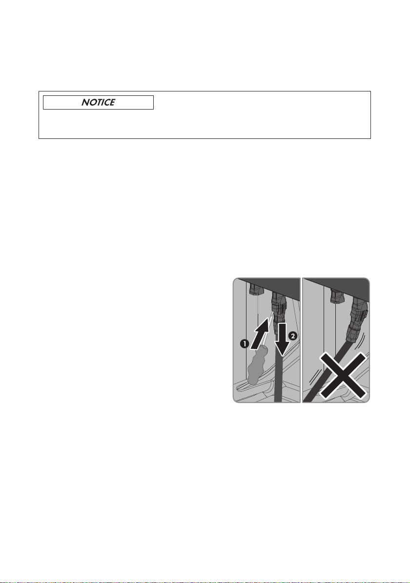
8. Release and remove all DC connectors. Insert a
slotted screwdriver or an angled screwdriver
(blade width 3.5mm) into one of the slide slots
and pull the DC connectors out downwards. Do
not pull on the cable.
9. Ensure that no voltage is present at the DC inputs of the inverter.
10. Use a suitable measuring device to check that no voltage is present at the AC connecting
terminal plate between L and N and L and PE. Insert the test probe (maximum diameter:
2mm) in each round opening of the terminal.
11. Flip the display up to have more space to make the measurement. Loosen the screw on the
display.
☑ The display clicks into place.
12. Ensure that no voltage is present between any terminal of the multifunction relay and PE of the
AC connecting terminal plate.
Service Manual 7SB30-60TL-21-SG-en-11
2 Safety
SMA Solar Technology AG
13.
Damage to the inverter due to electrostatic discharge
The internal components of the inverter can be irreparably damaged by electrostatic
discharge.
• Ground yourself before touching any component.
Service ManualSB30-60TL-21-SG-en-118
SMA Solar Technology AG
3 Cleaning the Inverter
3 Cleaning the Inverter
Damage to the display or the type label due to the use of cleaning agents
• If the inverter is dirty, clean the enclosure, the enclosure lid, the type label, the display and
the LEDs with a damp cloth only.
• If the cooling fins on the rear of the enclosure are dirty, clean them using a soft brush.
• If the air ducts on the top of the inverter are dirty, clean them using a soft brush.
Service Manual 9SB30-60TL-21-SG-en-11
4 Troubleshooting
SMA Solar Technology AG
4 Troubleshooting
4.1 LED Signals
The LEDs indicate the operating state of the inverter.
LED Status Explanation
Green LED glowing Feed-in operation
If an event occurs during feed-in operation, an event message will be shown on the display (for event messages see
the service manual at www.SMA-Solar.com).
flashing The conditions for feed-in operation are not yet met. As
soon as the conditions are met, the inverter will start feedin operation.
Red LED glowing Error
If an error occurs, the error message and the corresponding event number will be shown in the display. The error
must be rectified by a qualified person (for troubleshooting, see the service manual at www.SMA-Solar.com).
Blue LED glowing BLUETOOTH communication is activated.
4.2 Event Messages
Display message Cause
Self-test The self-test is in progress.
Set parameter The parameter changes are being adopted.
Parameters set successfully The parameter changes were successfully adopted.
Update file OK The update file found is valid.
SD memory card is read The SD memory card is searched for update files and the update file
is checked.
No new update SDcard The SD memory card contains an update file that has already been
used.
Update communication The inverter is performing an update of the communication compo-
nent.
Update main CPU The inverter is updating the inverter component.
Update RS485i module The inverter is updating the corresponding component.
Update Speedwire The inverter is updating the corresponding component.
Webconnect update The inverter is updating the corresponding component.
Update Bluetooth The inverter is updating the corresponding component.
Service ManualSB30-60TL-21-SG-en-1110
SMA Solar Technology AG
Display message Cause
Upd. language table The inverter is updating the corresponding component.
Update completed The inverter has successfully completed the update.
Grid param. unchanged The parameters are locked and you cannot change them.
Inst. code valid The entered GridGuard code is valid. Protected parameters have
now been unlocked and you can adjust the parameters. The param-
eters will be automatically locked again after tenfeed-in hours.
4 Troubleshooting
4.3 Error Messages
Event number Display message, cause and corrective measures
101 to 103
202 to 203, 205
Grid fault
The grid voltage or grid impedance at the connection point of the inverter is
too high. The inverter has disconnected from the utility grid.
Corrective measures:
• Check whether the grid voltage at the connection point of the inverter is
permanently in the permissible range.
If the grid voltage is outside the permissible range due to local grid
conditions, contact the grid operator. The grid operator must agree with
an adjustment of the voltage at the feed-in point or with a change of the
monitored operating limits.
If the grid voltage is permanently within the permissible range and this
message is still displayed, contact the Service (see Section11, page30
).
Grid fault
The utility grid has been disconnected, the AC cable is damaged or the grid
voltage at the connection point of the inverter is too low. The inverter has disconnected from the utility grid.
Corrective measures:
• Make sure that the circuit breaker is switched on.
• Make sure that the AC cable is not damaged.
• Make sure that the AC cable is correctly connected.
• Check whether the grid voltage at the connection point of the inverter is
permanently in the permissible range.
If the grid voltage is outside the permissible range due to local grid
conditions, contact the grid operator. The grid operator must agree with
an adjustment of the voltage at the feed-in point or with a change of the
monitored operating limits.
If the grid voltage is permanently within the permissible range and this
message is still displayed, contact the Service (see Section11, page30
).
Service Manual 11SB30-60TL-21-SG-en-11
 Loading...