

Page 1
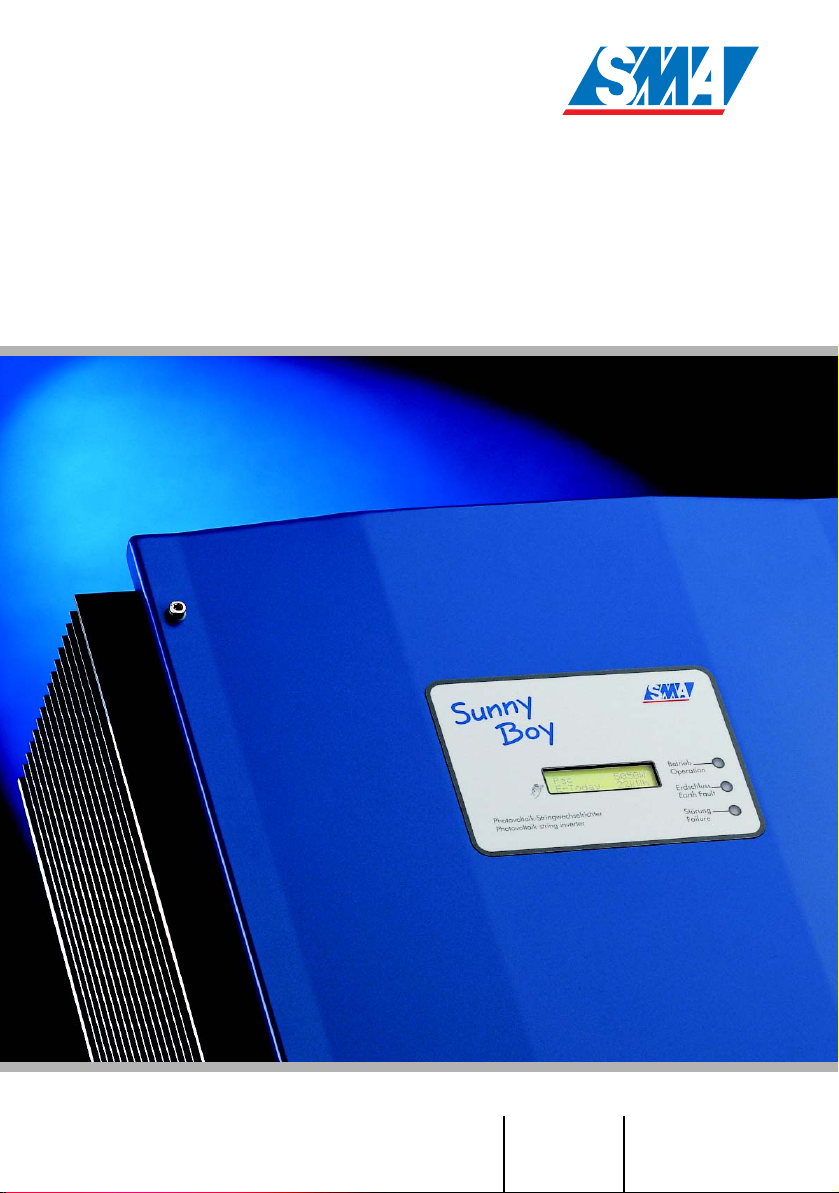
Sunny Boy 5000TL Multi-String
Transformerless Solar Inverter for Three
Independent Strings
Installation Guide Version 2.1 SB5000TL-12:SE2006
IME-SB5000TL
Page 2

Page 3
SMA Technologie AG Explanation of Symbols used in this Document
Explanation of Symbols used in this Document
This symbol indicates information that is essential for a trouble-free
and safe operation of the product. Please read these sections carefully in order to avoid any damages of the equipment and for optimal personal protection.
This symbol indicates information that is required for the optimal operation of
the product. Read these sections carefully in order to ensure an optimal operation of the product and all its features.
This symbol indicates an example.
Installation Guide SB5000TL-12:SE2006 Page 3
Page 4

Legal Restructions SMA Technologie AG
Liability exclusion
The information contained in this documentation are the property of SMA Technologie AG. No part of this
documentation may be published without written permission from SMA Technologie AG. A reproduction for
internal purposes for the evaluation of the product or an appropriate application is permitted and does not
require authorization.
All information are based on our "General Terms and Conditions of Delivery of SMA Technologie AG”.
The content of this documentation is reviewed continuously and adjusted, if necessar y. SMA Technologie
AG provides this documentation without exclusion of deviations and without warranty of completeness. You
will find the current version on the Internet at www.SMA.de or can obtain it via the usual sales channels.
Warranty or liability claims for all kinds are excluded in case of damages due to:
• Inappropriate use of the product
• Operation of the product in an improper environment
• Operation of the product without considering the relevant safety regulations
• Non-fulfillment of the warnings or safety instructions described in the documentation for the product
• Operation of the product under faulty conditions concerning security and protection
• Arbitrary changing of the product or the provided software
• Failure of the product due to interference of connected or contiguous devices out of legal limit values
• Disasters and force majeure
Software Licensing
The use of the provided software by SMA Technologie AG is subject to the following conditions:
The software may be reproduced for internal purposes and installed on any number of computers. Provided
source codes can be changed and adjusted on the company’s own authority according to the internal
purpose. Driver may be ported to other operating systems as well. No part of the source codes may be
published without written permission of SMA Technologie AG. Sublicensing of the software is not
acceptable.
Liability limitation: SMA Technologie AG disclaims liability for any direct or indirect consequential damages
arising from the use of the software produced by SMA Technologie AG. The same applies for the provision
and/or non-provision of support.
Provided software not produced by SMA Technologie AG is subject to the respective licensing and liability
agreements of the manufacturer.
Trademarks
All brand and product names used herein are trademarks or registered trademarks of their respective
holders, although they may not be specifically designated as such.
SMA Technologie AG
Hannoversche Strasse 1-5
34266 Niestetal
Germany
Tel. (+49) 5 61 95 22 – 0
Fax (+49) 5 61 95 22 – 100
www.SMA.de
E-Mail: info@SMA.de
© 2005 SMA Technologie AG. All rights reserved.
Page 4 SB5000TL-12:SE2006 Installation Guide
Page 5

SMA Technologie AG Table of Contents
Table of Contents
1 Introduction. . . . . . . . . . . . . . . . . . . . . . . . . . . . . . . . 7
2 Safety Instructions . . . . . . . . . . . . . . . . . . . . . . . . . . . 9
3 Overview . . . . . . . . . . . . . . . . . . . . . . . . . . . . . . . . 11
3.1 Device Description. . . . . . . . . . . . . . . . . . . . . . . . . . . . . . . . .11
3.2 External Dimensions . . . . . . . . . . . . . . . . . . . . . . . . . . . . . . .12
4 Requirements for the Installation . . . . . . . . . . . . . . . . 13
4.1 Requirements: Mounting Place . . . . . . . . . . . . . . . . . . . . . . . .13
4.2 Requirements: PV-Modules. . . . . . . . . . . . . . . . . . . . . . . . . . .15
4.3 Requirements: Grid 230 V (AC) . . . . . . . . . . . . . . . . . . . . . . .15
5 Installation . . . . . . . . . . . . . . . . . . . . . . . . . . . . . . . 19
5.1 Mounting . . . . . . . . . . . . . . . . . . . . . . . . . . . . . . . . . . . . . . .19
5.2 Electrical Installation . . . . . . . . . . . . . . . . . . . . . . . . . . . . . . .20
5.3 Activation . . . . . . . . . . . . . . . . . . . . . . . . . . . . . . . . . . . . . . .24
6 Opening and Closing the Sunny Boy 5000TL. . . . . . . 27
6.1 Opening the Sunny Boy 5000TL . . . . . . . . . . . . . . . . . . . . . . .27
6.2 Closing the Sunny Boy 5000TL. . . . . . . . . . . . . . . . . . . . . . . .27
7 Technical Documentation . . . . . . . . . . . . . . . . . . . . . 29
7.1 Data PV Generator Connection . . . . . . . . . . . . . . . . . . . . . . .29
7.2 Data Grid Connection . . . . . . . . . . . . . . . . . . . . . . . . . . . . . .29
7.3 Description of Device. . . . . . . . . . . . . . . . . . . . . . . . . . . . . . .30
7.4 Sunny Boy 5000TL Operating Parameters. . . . . . . . . . . . . . . .31
8 Exchanging Varistors . . . . . . . . . . . . . . . . . . . . . . . . 33
9 Sizing of a Circuit Breaker . . . . . . . . . . . . . . . . . . . . 37
10 Contact. . . . . . . . . . . . . . . . . . . . . . . . . . . . . . . . . . 39
Installation Guide SB5000TL-12:SE2006 Page 5
Page 6

Table of Contents SMA Technologie AG
Page 6 SB5000TL-12:SE2006 Installation Guide
Page 7

SMA Technologie AG Introduction
1 Introduction
The installation of the Sunny Boy may only be done by qualified
technicians. The installer must be approved by the utility company.
Please read the installation guide carefully before you begin with
the installation. The installation of utility interactive power sources
must be compliant with all applicable regulations of the utility
company and with all applicable regulations and standards.
The Sunny Boy 5000TL Multi-String is equipped with the SMA grid guard. This
is a type of independent disconnection device. It ensures that the Sunny Boy
5000TL Multi-String complies with the VDEW (Verband der
Elektrizitätswirtschaft – German Electricity Industry Association) regulations for
the connection and parallel operation of electrical power units to the lowvoltage grid of the electricity supply company and with DIN VDE 0126 (4.99)
which is a part of these regulations.
This installation manual is intended solely for qualified electricians. Its aim is to help
install and set up SMA Sunny Boy 5000TL Multi-String inverters quickly and correctly.
For detailed information on troubleshooting and on how to use the Sunny Boy
5000TL Multi-String, including information about the different communication
options, please see the operating instructions.
The „Sunny Design“ tool will help to dimension and check the size of your strings with
respect to the inverter you intend to use. Further information about „Sunny Design“
is available at www.SMA.de.
If your Sunny Boy is equipped with a communication interface, you will find detailed
instructions for installation in the description of the communication interfaces (PiggyBacks), which has been delivered with the device.
If you require further information, please call the Sunny Boy hotline on the following
number:
+49 561 95 22 - 499
Installation Guide SB5000TL-12:SE2006 Page 7
Page 8

Introduction SMA Technologie AG
Page 8 SB5000TL-12:SE2006 Installation Guide
Page 9
SMA Technologie AG Safety Instructions
2 Safety Instructions
Check your plant configuration and the
string sizing with „Sunny Design“ (available at www.SMA.de) or with the Sunny
Boy Hotline before you start with the installation. Exceeding the specifications
Erdschluss
Earth
F
ault
Art.-Nr.: 86-00
Work on the Sunny Boy with the lid removed must be carried out
by a qualified electrician. Hazardous and even lethal voltages can
be encountered within the enclosure. Before working on the Sunny
Boy with the lid removed, the AC and DC voltages MUST be
disconnected from the Sunny Boy and it must be sure that all
capacitors are discharged.
The Sunny Boy must be disconnected from the mains and
precautions must be taken to prevent the grid being reconnected.
In addition, the connections to the PV generator must be
disconnected.
with the input voltage will destroy the
Sunny Boy. Overvoltage on the DC side
can even cause dangerous explosions of
the Sunny Boys input capacitors and explosions of the electrolytes coming from
the exploded capacitors.
After isolating the AC and DC voltage you must wait approx. 30
minutes for the capacitors in the Sunny Boy to discharge. Only then
is it safe to open the unit by removing the lid. You must also make
sure that no voltage is present in the device.
The electronics inside your Sunny Boy 5000TL Multi-String is
vulnerable in terms of electrostatic discharge. Be sure to be
connected to ground (e.g. the enclosure of the Sunny Boy) before
handling anything within the enclosure of the Sunny Boy.
Installation Guide SB5000TL-12:SE2006 Page 9
Page 10

Safety Instructions SMA Technologie AG
Page 10 SB5000TL-12:SE2006 Installation Guide
Page 11
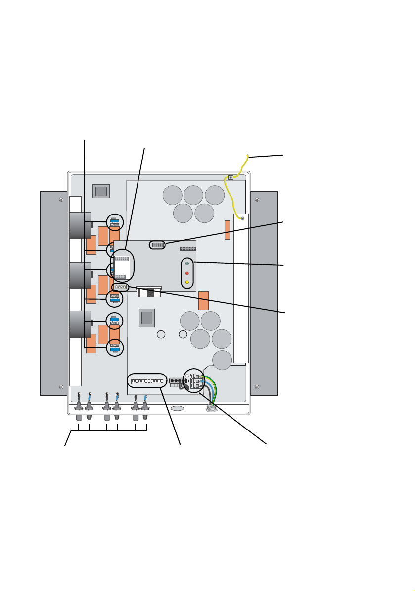
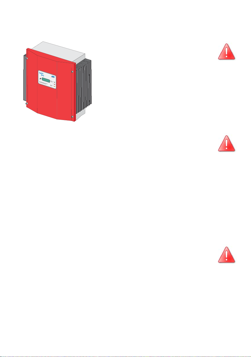
SMA Technologie AG Overview
(
3 Overview
3.1 Device Description
The following figure shows the different components and connection areas of an
open Sunny Boy 5000TL Multi-String inverter.
Varistors
page 33
Communication socket
RS485, NLM Piggy-Back, radio)
RS232,
PE connecting cable
for lid
Socket for display
unit (Sunny Display)
LEDs indicating
operating state
Communication
terminal
PV input plug (DC),
page 23
Installation Guide SB5000TL-12:SE2006 Page 11
Socket for PLC
(Powerline Communication)
power unit
Terminals (AC),
page 21
Page 12
Overview SMA Technologie AG
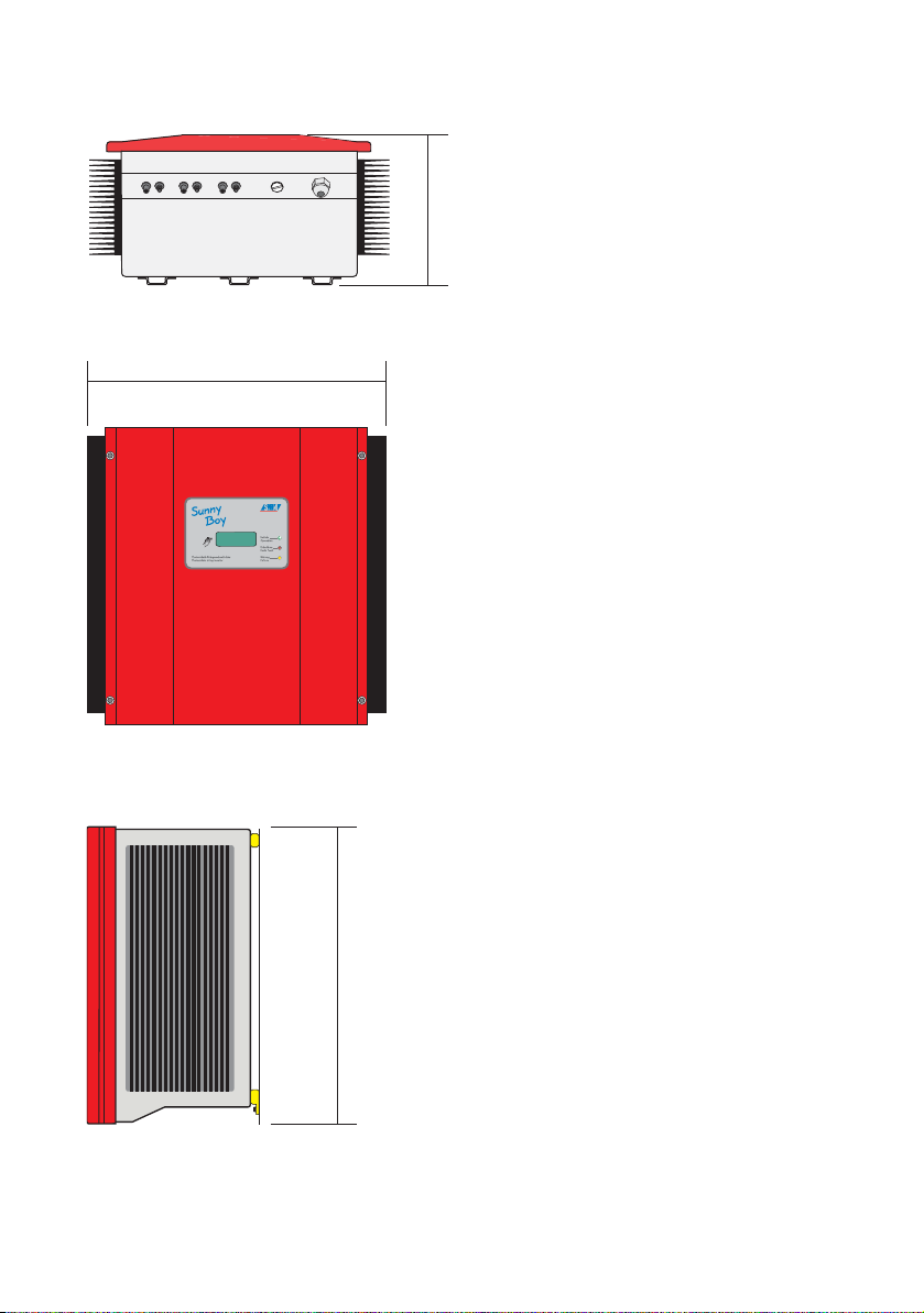
3.2 External Dimensions
225 mm
470 mm
Photovoltaik-Stringwechselrichter
Photovoltaic string inverter
490 mm
Page 12 SB5000TL-12:SE2006 Installation Guide
Page 13
SMA Technologie AG Requirements for the Installation
4 Requirements for the Installation
Please make sure to fulfill all conditions below before installing and commissioning
the Sunny Boy 5000TL Multi-String.
4.1 Requirements: Mounting Place
The Sunny Boy 5000TL Multi-String has a weight of 31 kg. Please
keep this in mind when selecting the place where and how to mount
the Sunny Boy 5000TL Multi-String.
The ambient temperature must be within -25 °C and +60 °C.
The Sunny Boy 5000TL Multi-String should be installed in a place
31 kg
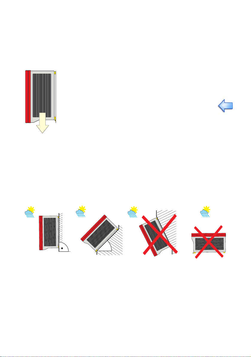
The Sunny Boy is designed to be mounted on a vertical wall. For an optimum energy
yield and the most convenient operation, vertical installation at eye-level is
preferable. In case it is absolutely necessary to tilt the Sunny Boy to the back the
maximum angle is 45 °. If installing the unit outdoors, make sure that it is not slanting
forwards. We advise against installing the unit in a horizontal position outdoors.
where it is not exposed to direct sunlight. An increased ambient
temperature can reduce the yield of the PV system.
It is not reccomended to install the Sunny Boy lying on the back side with the lid facing
upwards.
max. 45°
Install the Sunny Boy vertically, or if
necessary tilted slightly to the back.
Installation Guide SB5000TL-12:SE2006 Page 13
Never install the Sunny Boy
tilted to the front.
Page 14

Requirements for the Installation SMA Technologie AG
Important for the selection of the location:
Unintended removal of the PV plug connectors can damage the
connectors and even result in serious injuries. Install the Sunny Boy
5000TL Multi-String at a place where an unintended removal of the
PV plug connectors (e. g. by children) is not possible.
Some parts of the Sunny Boy can reach temperatures over 60 °C.
Do not install the Sunny Boy on flammable construction materials,
in areas where highly inflammable materials are stored or in potentially explosive environments!
Please make sure there is a sufficient space for heat dissipation! In a normal environment the following clearances should be provided for the Sunny Boy 5000TL MultiString:
Minimum clearances
Lateral 20 cm
Top 20 cm
Bottom 20 cm
Front 5 cm
In a living area the Sunny Boy 5000TL Multi-String
should not be mounted on plaster panels etc. in order
to avoid noises.
We recommend to install the inverter on a firm and
sturdy surface.
The Sunny Boy 5000TL Multi-String will emit a slight
noise during operation. This noise can be annoying
when the Sunny Boy is installed within a living area.
20 cm
20
cm
Photovoltaik-Stringwechselrichter
Photovoltaic string inverter
5
cm
20
cm
20 cm
Page 14 SB5000TL-12:SE2006 Installation Guide
Page 15

SMA Technologie AG Requirements for the Installation
4.2 Requirements: PV-Modules
The Sunny Boy 5000TL Multi-String is designed for the connection of up to three
strings (PV modules connected in series). The three strings may be different in terms
of type, module number and orientation due to the fact that each input string is processed by a separate MPP-tracker.
The „Sunny Design“ tool will help to dimension and check the size of your string with
respect to the inverter you intend to use. Information about the „Sunny Design“ tool
is available at www.SMA.de.
The device has six PV plug connectors (two for each string). The connecting cables
of the PV panel therefore have to be equipped with such plug connectors as well.
A connection kit for the connection of loose cable ends in a string can be purchased
as an accessory. In the following you find the SMA order numbers for the different
PV plug connectors:
• Multi-Contact 3 mm: „SWR-MC“
• Multi-Contact 4 mm: „MC-SET“
• Tyco: „TYCO-SET“
Limits for DC input
max. voltage per string 750 V (DC)
max. input current per string 7,5 A (DC)
Caution: A parallel connection of the DC input is not possible!
4.3 Requirements: Grid 230 V (AC)
The relevant technical regulations as well as specific requirements defined by the local public utility have to be
complied with.
The terminals of the Sunny Boy 5000TL Multi-String are
suitable for cables with a cross-section of up to 10 mm². Their outer diameter should
be between 9 mm and 17 mm. The Sunny Boy 5000TL Multi-String is connected with
three wires (L, N, PE).
Each connection to a Sunny Boy 5000TL Multi-
Photovoltaik-Stringwechselrichter
Photovoltaic string inverter
Installation Guide SB5000TL-12:SE2006 Page 15
String must be equipped with a separate automatic circuit breaker 25 A type B. No other con-
25A
B
sumers may be connected to the cable.
max. 10 mm²9 … 17 mm
Page 16

Requirements for the Installation SMA Technologie AG
Sizing of a circuit breaker for the AC line of a photovoltaic inverter for utility interaction
Several factors have to be considered when you define the size of the circuit breaker
for your PV-plant:
• cable type (material and isolation)
• ambient temperature surrounding the cable (higher temperatures reduce the conducting capacity of the cable)
• type of installation for the cable (can reduce the conducting capacity of the cable)
• bundling of cables (can reduce the conducting capacity of the cable)
• loop impedance [Z] (reduces the current that flows in case of a ground fault current through a body and has influence on the tripping characteristics of the circuit
breaker)
• Adequate clearance between the circuit breakers in order to avoid excessive
heating (automatic circuit breakers trip earlier when they are warmer.).
• fuse selectivity
• protection class of the connected consumer (VDE 0100 Part 410 "Protection
against electric shock"
The following standards have to be complied with:
1
and/or the international standard IEC 364-4-41:1992)
• DIN VDE 0298-4
• DIN VDE 0100 Part 430
1
("Types of cable installation and conducting capacity")
1
("Protection measures for protection of cables
and conductors in terms of overcurrent") and/or the international standard IEC 364-4-43:1977 and IEC 364-4-473:1977
1
• VDE 0100 Part 410
("Protection against electric shock") and/or the inter-
national standard IEC 60364-4-41:1992
An example for determining the rating of the AC circuit breaker is specified in detail
in chapter 8 „Exchanging Varistors” (page 33).
Do not equip the AC circuit with a 30 mA GFCI (Ground Fault Current Interruptor) that trips when the residual failure current to the equipment ground (PE)
exceeds 30 mA.
The Sunny Boy 5000TL Multi-String constantly monitors the ground currents of the PVplant (PV-modules, cables and inverter) and disconnects from the grid when the
ground fault current deviations exceed 30 mA. The inverter automatically distinguishes between real failure currents and normal capacitive discharge currents.
1. The standards mentioned above are to be only used as a guideline for your
installation. They apply for installations in Germany. Please note that other
standards will apply for different countries throughout the world.
Page 16 SB5000TL-12:SE2006 Installation Guide
Page 17

SMA Technologie AG Requirements for the Installation
The Sunny Boy 5000TL Multi-String does not generate any extraordinary capacitive
discharge currents in normal operation. In certain cases (e.g. the internal testing of
the safety components within the Sunny Boy 5000TL Multi-String) discharge currents
can occur that can trip a 30 mA GFCI.
Install a 100 mA GFCI in the AC distribution in case an additional GFCI is absolutely necessary.
The system impedance at the installation site of the Sunny Boy 5000TL Multi-String
must be less than 1 Ohms for the islanding detection and the fuses to work porperly.
Furthermore you should have a suitable cable cross-section in order to keep the losses below 1 % at nominal power. The according losses with respect to cable length
and cross-section are illustrated below. It is based on a multi-conduit cable with all
conduits made of copper.
1.4%
1.2%
1.0%
0.8%
0.6%
Losses
0.4%
0.2%
0.0%
5 m 10 m 20 m 30 m 40 m 50 m
0 m 15 m 25 m 35 m 45 m
Do not use cables where the losses will exceed 1.0 %
10.0 mm²
4.0 mm²
6.0 mm²
8.0 mm²
Length
The maximum cable lengths for the different cable cross-sections are as follows:
Conductor cross-section 4.0 mm² 6.0 mm² 8.0 mm² 10.0 mm²
Max. length 12 m 18 m 24 m 31 m
Installation Guide SB5000TL-12:SE2006 Page 17
Page 18

Requirements for the Installation SMA Technologie AG
The Sunny Boy 5000TL Multi-String is designed for 230 V grids. The voltage should
be within 198 V and 260 V and the frequency should be within 49.8 Hz and
50.2 Hz. All settings shown below are based on the German standard DIN VDE
0126. You are also able to use other settings.
Limits for AC output
Voltage range 198 V ... 260 V
Frequency range 49.8 Hz ... 50.2 Hz
Voltage range
(without anti-islanding)
Frequency range
(without anti-islanding)
180 V ... 260 V
45.5 Hz ... 54.5 Hz
Page 18 SB5000TL-12:SE2006 Installation Guide
Page 19

SMA Technologie AG Installation
5 Installation
5.1 Mounting
For trouble-free mounting of the Sunny Boy 5000TL
Multi-String we recommend to use the bracket for wall
installation included in delivery. You can mount it vertically in firm concrete or stone walls with e. g. stainless
steel 8 mm x 50 mm hexagon screws according to DIN
571, an appertaining washer and with an 8 mm dowel.
P
h
otov
o
lt
Pho
ai
k
-
t
S
o
t
v
ri
o
ng
l
t
a
w
i
c
e
chs
s
tr
i
ng
el
rich
i
nv
t
er
er
ter
Keep the weight of the Sunny Boy 5000TL Multi-String
(31 kg) in mind.
1. Mount the bracket. To mark the positions for drill
holes you can also use the bracket as a drilling
template.
2. Hang the upper fixing straps of the Sunny Boy
5000TL Multi-String into the bracket (2) so that it
cannot be shifted sideways any more.
3. Secure the Sunny Boy 5000TL Multi-String against
lifting off by screwing the M6x10 screw (included
in delivery) into the lower middle fixing strap (3).
4. Ensure the Sunny Boy 5000TL Multi-String has
been tightly fastened.
2
1
3
Installation Guide SB5000TL-12:SE2006 Page 19
Page 20

Installation SMA Technologie AG
5.2 Electrical Installation
Check the correct polarity before you connect the PV strings!
The following figure shows the complete cabling of a Sunny Boy 5000TL Multi-String:
Page 20 SB5000TL-12:SE2006 Installation Guide
Page 21

SMA Technologie AG Installation
Connection of AC output
Please follow the steps below:
1. Check the grid voltage. If it is above 260 V
(German standard), the Sunny Boy 5000TL
Multi-String stops operation. The local public
utility company should solve this problem.
2. Disconnect the grid (switch off the circuit
breaker), secure it against accidental
reactivation and ensure that it is disconnected.
The maximum grid voltage for feeding
max. 260 V!
operation is 260 V!
+- +- +-
3. Unscrew the lid from the enclosure of the Sunny
Boy 5000TL Multi-String and carefully remove
the lid. Then pull the PE cable off the inside of
the lid.
4. Connect the AC cable as illustrated in the figure
on the side. Use the cable gland that is included
in the delivery of your Sunny Boy 5000TL MultiString. Phase (L) and Neutral (N) may not be
mixed up.
String B
String C
String A
Before opening the Sunny Boy 5000TL
Multi-String check whether the AC
output is safely isolated from supply!
Photovoltaik-Stringwechselrichter
Photovoltaic
s
tring
i
nverter
Make sure that you pull off the green
yellow PE cable from the inside of the
Sunny Boy when you open it!
L
N
Connection of „L“ and „N“
Installation Guide SB5000TL-12:SE2006 Page 21
Page 22

Installation SMA Technologie AG
5. Connect the earth wire (PE) of the mains lead to
the top terminal of the three-terminal block on
the circuit board.
Connection of PE conductor
6. Fix the PE conductor on the lid again. Fasten the lid to the enclosure of the Sunny
Boy 5000TL Multi-String by tightening the four screws.
Do not switch on the circuit breaker yet! The Sunny Boy 5000TL
Multi-String may only be connected to the AC grid when the PV
strings have been connected and the device is tightly closed.
Page 22 SB5000TL-12:SE2006 Installation Guide
Page 23

SMA Technologie AG Installation
PV String (DC) Connection
Connect the PV strings as follows:
1. Check the PV generator connections on their
correct polarity and compliance with the maximum string voltage of 750 V DC, see chapter
4.2 „Requirements: PV-Modules” (page 15).
The voltage from the strings is very dangerous! Be very careful
and pay attention to all applicable safety regulations!
2. Measure the DC voltages between each PV plug
connector of a string and ground potential.
Follow the safety instructions!
3. If the measured voltages are constant and their
total approximately corresponds to the opencircuit voltage of the string, a ground fault has
occured in this string. The ratios of voltages
approximately indicate where the ground fault
can be found.
PE
When you have found a ground fault in a string, only connect it to
the Sunny Boy 5000TL Multi-String after you have removed the
cause for the ground fault in the PV generator.
4. Repeat steps 2 and 3 for each string.
5. Connect the trouble-free PV strings to the Sunny
Boy 5000TL Multi-String. Make sure to connect
them with correct polarization.
+- +- +-
6. Close off the unneeded DC input sockets using
the protective caps supplied in the accessories
String B
String C
kit.
Installation Guide SB5000TL-12:SE2006 Page 23
String A
When connecting the plus and minus
poles of a string make sure to choose
the correct connection!
Page 24

Installation SMA Technologie AG
5.3 Activation
You can activate the Sunny Boy 5000TL Multi-String when:
• The AC (grid) cable has been correctly connected.
• All the DC (PV) strings have been connected and all unused PV plug connectors
on the underside of the inverter have been closed with the protecting caps.
• The lid has been tightly screwed on.
Proceedings for Activation
1. Switch the circuit breaker on.
2. Check whether the LEDs indicate trouble-free
operation of the Sunny Boy 5000TL Multi-String
based on the table on the next page. If this is the
case commissioning has been successfully
completed.
On!
Off
Photovoltaik-Stringwechselrichter
Photovoltaic string inverter
If the lower yellow LED repeatedly blinks once a second for four
times, immediately disconnect the grid voltage and the PV generator from the Sunny Boy 5000TL Multi-String. The input voltage is
too high. The inverter might be damaged!
Check whether string voltages comply with limiting values stated in chapter 4.2 „Requirements: PV-Modules” (page 15). If the values are too high, the planner / installer
of the PV generator must modify the strings.
If the LED blinks again when the PV plant is reconnected to the inverter although
string voltages have been checked to be ok, disconnect the PV panel again and contact SMA Technologie AG (see chapter 10 „Contact” (page 39)).
Page 24 SB5000TL-12:SE2006 Installation Guide
Page 25

SMA Technologie AG Installation
Green Red Yellow Status
off off OK (feeding)
permanently on
blinking fast
(3 x per second)
blinking slowly
(1 x per second)
shortly turns off
(approx. 1 x per
second)
off
permanently on
off off OK (Stop)
permanently on off failure
off off
permanently on permanently on failure
off off OK (derating)
permanently on off failure
off
permanently on
off failure
permanently on OK (Initialization)
OK (waiting, grid moni-
toring)
off OK (stand-by)
off / blinking failure
off failure
off / blinking failure
You will find a detailed description of failure messages and their causes in the „Operating Instructions“.
Installation Guide SB5000TL-12:SE2006 Page 25
Page 26

Installation SMA Technologie AG
Page 26 SB5000TL-12:SE2006 Installation Guide
Page 27

SMA Technologie AG Opening and Closing the Sunny Boy 5000TL
6 Opening and Closing the Sunny Boy 5000TL
If the inverter has to be openend, always follow the safety instructions given in chapter 2 „Safety Instructions” (page 9).
6.1 Opening the Sunny Boy 5000TL
Caution: Stick to the order specified below!
1. Switch off the AC connection.
2. Prevent accidental reconnection!
3. Disconnect the PV generator from the Sunny Boy 5000TL Multi-String by pulling
off all the connectors.
4. Wait 30 minutes! (This is necessary to let the internal capacitors
discharge.)
5. Remove the four screws on the lid and pull the lid slightly forward. Unlock the
green-yellow PE connection and remove it from the lid and take the lid off.
6.2 Closing the Sunny Boy 5000TL
Caution: Stick to the order specified below!
1. Connect the PE conductor to the lid. Then attach the lid to the enclosure of the
Sunny Boy 5000TL Multi-String by tightening the four screws.
2. Connect the PV generator. Make sure to connect each plug to the correct
terminal.
3. Switch on the AC circuit breaker. This activates the Sunny Boy 5000TL MultiString.
4. Check whether the LEDs of the Sunny Boy 5000TL Multi-String indicate troublefree operation.
Installation Guide SB5000TL-12:SE2006 Page 27
Page 28

Opening and Closing the Sunny Boy 5000TL SMA Technologie AG
Page 28 SB5000TL-12:SE2006 Installation Guide
Page 29

SMA Technologie AG Technical Documentation
7 Technical Documentation
7.1 Data PV Generator Connection
Max. input open-circuit voltage U
Input voltage, MPP operation U
Max. input current I
Max. input power P
PV max
PV
Recommended generator power 6600 Wp
All-pole disconnector
on DC input side
Surge voltage protection thermally monitored varistors
Voltage ripple U
Personnel protection Ground Fault monitoring (Riso > 1 MΩ)
Internal consumption in operation < 10 W (stand-by)
Pole confusion prevention by short-circuit diode
7.2 Data Grid Connection
Nominal output power P
Peak output power P
Nominal output current I
Harmonic distortion of output
(with K
)
om
< 2 %, PAC > 0,5 P
Unom
Short-circuit resistance Imax = 30 A
Operating range, grid voltage U
Operating range, grid frequency f
All-pole disconnector on grid side independent disconnection device
Phase difference
(related to basic wave of current)
Overvoltage category III
Test voltage (50 Hz) 1.65 kV (5 s unit / type test)
Surge voltage test 4 kV (1.2/50 ms)
Internal consumption in stand-by 0.25 W
ACNenn
THD
ACn-
AC
cos Phi 1
750 V (at -10 °C Module Temperature)
PV 0
125 V ... 750 V DC
PV
7,5 A per input port
3800 W per String
DC plug connector standard - other snap
cable connectors optional
< 10 % of input voltage
PP
AC nom
ACm ax
4600 VA
5100 W
20 A
< 4 %
IAC
198 ... 260 V AC
AC
49.8 ... 50.2 Hz
(MSD), (2 independant systems)
(serial interface: 6 kV)
Installation Guide SB5000TL-12:SE2006 Page 29
Page 30

Technical Documentation SMA Technologie AG
7.3 Description of Device
You will find a detailed device description in the Operating Instructions.
General Data
Protection Degree according to
DIN EN 60529 IP65
Dimensions (width x height x depth) approx. 470 mm x 490 mm x 225 mm
Weight approx. 31 kg
External Interfaces
Data transmission via Powerline optional
Data transmission via separate data cable optional,
RS232 / RS485, electrically separated
Data transmission via radio optional
Efficiency
Max. efficiency at nominal voltage η
European weighted efficiency η
max
euro
The efficiency of the Sunny Boy 5000TL Multi-String depends on the input DC voltage
coming from the PV modules. The higher the voltage the higher is the efficiency of the
Sunny Boy 5000TL Multi-String.
95,5 %
94,5 %
Page 30 SB5000TL-12:SE2006 Installation Guide
Page 31

SMA Technologie AG Technical Documentation
7.4 Sunny Boy 5000TL Operating Parameters
Any unauthorized modifications of the operating parameters can
• result in serious injuries or casualties due to altered internal
safety precautions within the Sunny Boy
• void the operating permission of the Sunny Boy
• void the warranty of the Sunny Boy
Never change the operating parameters with out explicit permission and instructions!
Name Unit Range Default
Betriebsart/
Operating Mode
Default GER/ENS
dFac-MAX Hz/s 0.005 ... 4.0 0.25
dZac-MAX mOhm 0 ... 2000 350
E_Total kWh 0 ... 200000
Fac-Delta- Hz 0 ... 4.5 (0.19) 0.19
Fac-Delta+ Hz 0 ... 4.5 0.19
h_Total h 0 ... 200000
Inst.-Code
NiTest/
impedance test
Riso-Min kOhm 1000 ... 30000 1000
Speicherfunktion/
Memory Function
Speicher/
Storage
Uac-Max/
Vac-Max
Uac-Min/
Vac-Min
Usoll-Konst A/
Vconst-SetpointA
Usoll-Konst B/
Vconst-SetpointB
Usoll-Konst C/
Vconst-SetpointC
V 180 ... 300 261
V 180 ... 300 198
V 0 ... 750 290
V 0 ... 750 290
V 0 ... 750 290
MPP/
Ikonst/
UKonst/
Stop
0 / 1 1
permanent/
volatile
MPP
none
permanent
Installation Guide SB5000TL-12:SE2006 Page 31
Page 32

Technical Documentation SMA Technologie AG
The following parameters appear in parameter list but cannot be modified:
Name Unit Range Description
Plimit W 5100 Upper limit of AC output power
SMA-SN Serial Number of the Sunny Boy
Software-BFR/
Firmware-BFR
Software-SRR/
Firmware SRR
Hardware-DC-BFS Hardware version of the DC converter control unit (DC -
Firmware-DC-BFS Firmware version of the DC converter control unit (DC -
Firmware version of the operation control unit (BFR)
Firmware version of the current control unit (SRR)
BFR)
BFR)
Page 32 SB5000TL-12:SE2006 Installation Guide
Page 33

SMA Technologie AG Exchanging Varistors
8 Exchanging Varistors
The Sunny Boy 5000TL Multi-String is a very complex technical device. Therefore
there are only a few possibilities to repair failures on site. Please do not try to make
repairs otherwise than described in this document. Make use of our exchange service
and the repair service of SMA Technologie AG.
If the red status LED is permanently on during operation please first make sure that
there is no ground fault in the PV generator. Only if the green LED is permanently on
at the same time, you can skip points 3 to 5 below.
1. Disconnect the grid (switch off the circuit breaker), secure it against accidental reactivation and
ensure that it is disconnected.
Off!
1. 2. 3.
Ensure that the AC voltage is off before
you open the Sunny Boy 5000TL Multi-
2. Disconnect the DC plug connectors of all strings.
Make sure that their allocation to the different
inverter input ports can still be recognized!
String!
+- +- +-
String B
String C
String A
Disconnect the PV strings!
3. Measure voltages between one PV plug
connector of each string and the ground
potential. Follow all applicable safety
instructions!
PE
Measure voltages between PV plug
connectors and the ground potential.
The voltage from the strings is very dangerous! Be very careful
and pay attention to all applicable safety regulations!
4. If the voltages measured are constant and their total is approximately equal to
the open-circuit voltage of the string, there is a ground fault in this string. Its
appoximate position can be deducted from the ratios of voltages.
Installation Guide SB5000TL-12:SE2006 Page 33
Page 34

Exchanging Varistors SMA Technologie AG
5. Repeat points 3 and 4 for each string.
If you have found a ground fault it is probably unnecessary to exchange the
varistors. Make sure to remove the ground fault instead. This should normally
be done by the installer of the PV plant. In this case proceed with point 10, but
with-out reconnecting the faulty string! Protect its PV plug connectors against
touching (e. g. by protective caps or insulation strip with sufficient electric
strength).
If you have not found any ground fault in the PV generators, probably one of
the thermally monitored varistors has lost its protective function. The varistors
are subject to wear and tear and their function is reduced in the course of their
aging or in case of repeated strain placed on them by surge voltages. You can
now check the varistors as described below while following the safety
instructions given in chapter 2 „Safety Instructions” (page 9).
6. Unscrew the lid of the Sunny Boy 5000TL Multi-String and remove it. Disconnect
the PE plug inside the lid. Test safe isolation from supply.
7. Test all varistors for an electric connection between terminals 2 and 3. If there
is no electric connection the varistor is useless. The position of varistors in the
Sunny Boy 5000TL Multi-String can be seen in chapter 3.1 „Device Description”
(page 11).
8. Replace the defective varistor by a new one as
shown in the figure on the left. Ensure correct
orientation of the varistor! Please contact SMA
if you have not received special tools to move
the terminals (included in delivery of
Unlock the varistor
with the
extractor tool
replacement varistors). However, the terminal
contacts can also provisionally be released one
by one with a suitable screwdriver. The failure
of a varistor is normally due to circumstances
Remove varistor
that apply to all varistors in a similar manner
(temperature, age, induced surge voltages).
We therefore strongly recommend not only to
exchange the defective one, but all six. These
varistors are specially manufactured for use in
123
The wire with the little
dent must be inserted
into the terminal
number 1 when you
install the new varistor
the Sunny Boy 5000TL Multi-String and are not
commercially available. They have to be
purchased from SMA Technologie AG direct
(SMA order name:“MSWR-TV-6“).
Page 34 SB5000TL-12:SE2006 Installation Guide
Page 35

SMA Technologie AG Exchanging Varistors
9. If no replacement varistors are available on site
the Sunny Boy 5000TL Multi-String can also be
operated without them for a limited period of
time. To this end remove the varistors you have
found to be defective and equip the terminals
with a wire jumper between terminals 2 and 3
instead. The Sunny Boy 5000TL Multi-String is
then not protected against surge voltages!
1 2 3
For a limited period of time a defective
varistor can be replaced by a wire
between terminal 2 and 3.
The input port thus modified is no longer protected against surge
voltages! Equip the inverter with varistors again as soon as possible. The Sunny Boy 5000TL Multi-String should not be operated
without varistors in plants where is a high risk of surge voltages!
10. Reconnect the PE plug to the lid and close the
Sunny Boy 5000TL Multi-String again.
11. Connect the faultless strings of the PV panel.
Ensure correct allocation to strings.
12. Close off the unneeded DC input sockets using
+- +- +-
the protective caps supplied in the accessories
kit.
String B
String C
String A
13. Switch on the circuit breaker.
14. Check whether the LEDs of the Sunny Boy
On!
5000TL Multi-String show trouble-free
operation.
Off
If you have found neither a ground fault nor a defective varistor there probably is a
fault in the Sunny Boy 5000TL Multi-String. Please contact the SMA hotline in this case
to discuss further proceedings.
Installation Guide SB5000TL-12:SE2006 Page 35
Page 36

Exchanging Varistors SMA Technologie AG
Page 36 SB5000TL-12:SE2006 Installation Guide
Page 37

SMA Technologie AG Sizing of a Circuit Breaker
9 Sizing of a Circuit Breaker
Example for the sizing of a circuit breaker for the AC line of a photovoltaic inverter for utility interaction in terms of temperature.
Photovoltaic plant with 9 inverters type Sunny Boy 5000TL Multi-String with 3
inverters per phase
0
0
6
8
:
.
r
N
.
t
r
A
L1
L2
L3
0
0
6
8
:
.
r
N
.
t
r
A
0
0
6
8
:
.
r
N
.
t
r
A
...
0
0
6
8
:
.
r
N
.
t
r
A
0
0
6
8
:
.
r
N
.
t
r
A
0
0
6
8
:
.
r
N
.
t
r
A
N
Required data of the used inverters:
• max. output current: 22 A
• max. permissible rating of the circuit breaker for one inverter: 25 A
The type of cable as well as the type of cable installation and several other conditions
have influence on the maximum rating of the circuit breaker for the inverter.
• In this example we assume that the cable used (6 mm²) can be used for nominal
currents up to 32.2 A in this example.
Selection of the circuit breakers:
• The maximum possible nominal current of the cable used and the maximum pos-
sible rating for the inverter now define the maximum possible nominal current of
the circuit breakers.
• 25 A are possible in our example for one inverter.
The circuit breakers must also be selected according to their thermal characteristics.
Several aspects that have affect on the load must be considered when you select a
circuit breaker. These aspects are specified in the data sheets of the circuit breakers.
Example for the sizing of a 25 A circuit breaker with B characteristics for the
AC line of a photovoltaic inverter for utility interaction while the circuit breakers are installed right next to each other without gap (with respect to the thermal conditions).
Installation Guide SB5000TL-12:SE2006 Page 37
Page 38

Sizing of a Circuit Breaker SMA Technologie AG
One vendor of circuit breakers for example specifies the ratings for an ambient temperature of 50 °C.
Aspects that have an affect on the load specified in the data sheets:
• Reduction of the tolerable current because of continuous load > 1 h = 0.9
• Reduction of the tolerable current due to installation of 9 circuit breakers right
next to each other without gap = 0.77
• Increase of the tolerable current resulting from ambient temperatures of 40 °C in
the distribution box = 1.07
3
2
1
Result:
The nominal current of the circuit breaker is
Inr = 32 A x 0.9 x 0.77 x 1.07 = 23.7 A
The circuit breaker selected for this installation is not suitable due to the fact that the
maximum tolerable current of the circuit breaker is below the maximum current of the
used inverter. It will trip in normal operation.
A solution for this plant would be the installation of the circuit breakers with an 8 mm
gap between each unit. This would result in a reduction coefficient of 0.98 instead of
0.77. This would result in a maximum current of 23.6 A.
Beside the sizing of the circuit breakers in terms of thermal characteristics it is necessary to comply with all other applicable standards 4. These are especially:
• DIN VDE 0100 Part 410 and/or the international standard IEC 364-4-41:1992
• DIN VDE 0100 Part 430 and/or the international standard IEC 364-4-43:1977
and IEC 364-4-473:1977
• DIN VDE 0298 Part 4
1. In photovoltaic applications continuous loads of over 1 h are possible.
2. The coefficient is 1 in case there is only one single circuit breaker.
3. Resulting from the sizing of the circuit breakers for ambient temperatures of
50 °C.
4. The standards listed here are standards that apply in Germany. Please note
that other standards apply in other countries. Beside the standards above other standards may be applicable in special installations.
Page 38 SB5000TL-12:SE2006 Installation Guide
Page 39

SMA Technologie AG Contact
10 Contact
If you have any questions or technical problems with the Sunny Boy 5000TL MultiString our hotline will be glad to help you. Please keep the following data ready
when calling SMA:
• Type of inverter used
• Connected modules and number of modules
• Communication
• Serial number of the Sunny Boy
Address:
SMA Technologie AG
Hannoversche Strasse 1 - 5
34266 Niestetal
Germany
Tel.:+49 (561) 95 22 - 499
Fax:+49 (561) 95 22 - 4699
hotline@SMA.de
www.SMA.de
Installation Guide SB5000TL-12:SE2006 Page 39
Page 40

Contact SMA Technologie AG
Page 40 SB5000TL-12:SE2006 Installation Guide
Page 41

Page 42

SMATechnologie AG
www.SMA.de
Hannoversche Straße 1–5
34266 Niestetal
Germany
Tel. +49 561 9522 - 0
Fax +49 561 9522 - 100
www.SMA.de
SMA America, Inc.
12438 Loma Rica Drive, Unit C
Grass Valley, CA 95945
USA
Tel. +1 530 273 4895
Fax +1 530 2747 271
www.SMA-AMERICA.com
SMA Solartechnology China
Room 20F, InternationalMetro Center,
Building A , City Square No. Jia 3,
Shilipu Road, Changyang District
100025 Beijing, PR. China
Tel. +86 10 65 58 78 15
Fax +86 10 65 58 78 13
www.SMA-CHINA.com
 Loading...