

Page 1
5WPP[$Q[7
+PUVCNNCVKQP)WKFG
Page 2

Page 3
Installation Guide
Copyright © 2005 SMA America, Inc. All rights reserved.
No part of this document may be reproduced, stored in a retrieval system, or
transmitted, in any form or by any means, electronic, mechanical, photographic,
magnetic or otherwise, without the prior written permission of SMA America, Inc.
SMA America makes no representations, express or implied, with respect to this
documentation or any of the equipment and/or software it may describe, including
(with no limitation) any implied warranties of utility, merchantability, or fitness for
any particular purpose. All such warranties are expressly disclaimed. Neither SMA
America nor its distributors or dealers shall be liable for any indirect, incidental, or
consequential damages under any circumstances.
(The exclusion of implied warranties may not apply in all cases under some
statutes, and thus the above exclusion may not apply.)
Specifications are subject to change without notice. Every attempt has been made
to make this document complete, accurate and up-to-date. Readers are cautioned,
however, that SMA America reserves the right to make changes without notice and
shall not be responsible for any damages, including indirect, incidental or
consequential damages, caused by reliance on the material presented, including,
but not limited to, omissions, typographical errors, arithmetical errors or listing
errors in the content material.
Revision History
Rev. No. Date By Version
1.0 May 04, 2005 YS 1st Edition
2.0 June, 2005 JP 1st US Edition
2.1 August, 2005 JP 2nd US Edition
2.2 November, 2005 JP 3rd US Edition
2.3 February, 2006 JP 4th US Edition
2.4 May, 2006 JP 5th US Edition
SMA America, Incorporated
12438 Loma Rica Drive
Grass Valley, California 95945
Tel 530.273.4895
Fax 530.274.7271
www.sma-america.com
SB3800U-12:SE2006 SMA America i
Page 4
Installation Guide
IMPORTANT SAFETY INSTRUCTIONS
SAVE THESE INSTRUCTIONS
This manual contains important instructions for the Sunny Boy 3800U that must be
followed during installation and maintenance of the inverter.
The Sunny Boy is designed and tested according to international safety requirements,
but as with all electrical and electronic equipment, certain precautions must be observed
when installing and/or operating the Sunny Boy. To reduce the risk of personal injury
and to ensure the safe installation and operation of the Sunny Boy, you must carefully
read and follow all instructions, cautions and warnings in this Installation Guide.
Safety and Hazard Symbols
This symbol is used to call attention to important information that
you must have when installing and/or operating the Sunny Boy.
Failure to read and follow instructions marked with this symbol
could result in injury or death and/or damage to the equipment.
This symbol appears beside instructions and warnings that deal
with dangerous voltages that can injure or kill people who come
in contact with them.
This symbol appears beside terminations that are connected to
earth-ground.
ii SMA America SB3800U-12:SE2006
Page 5
Installation Guide
Warnings
WARNING: A Warning describes a hazard to equipment or
personnel. It calls attention to a procedure or practice, which,
if not correctly performed or adhered to, could result in damage to or destruction of part or all of the SMA equipment and/
or other equipment connected to the SMA equipment or personal injury.
Warnings and Cautions may also be accompanied by one or more of the safety and
hazard symbols described above to indicate the type of hazard described therein.
Other Symbols
In addition to the safety and hazard symbols described on the previous pages, the
following symbol is also used in this Installation Guide:
This symbol accompanies notes that call attention to supplementary
information that you should know and use to ensure optimal operation
of the system.
All electrical installations must be done in accordance with
the local and National Electrical Code ANSI/NFPA 70.
The Sunny Boy contains no user-serviceable parts except
for the fan on the bottom of the enclosure and the filter
behind the fan as well as the exhaust fin on the left hand
side of the unit. For all other repair and maintenance
always return the unit to an authorized SMA Service
Center.
Before installing or using the Sunny Boy, read all of the
instructions, cautions, and warnings on the Sunny Boy, the
PV array, and in this Installation Guide.
Before connecting the Sunny Boy 3800U to the electrical
utility grid, contact the local utility company. This
connection must be made only by qualified personnel.
SB3800U-12:SE2006 SMA America iii
Page 6
Installation Guide
PV arrays produce electrical energy when exposed to light
and thus can create an electrical shock hazard. Wiring of
the PV-arrays should only be performed by qualified
personnel.
Warranty
All Sunny Boy inverters sold in the USA have a five-year warranty, as indicated on the
warranty card included in the Sunny Boy shipping container. For warranty coverage, or
if you have questions about the Sunny Boy warranty, contact SMA America at the
address, telephone number or Web site listed on
section of the SMA America Web site).
page i (to send E-mail, see the Contact
iv SMA America SB3800U-12:SE2006
Page 7

Contents
Revision History . . . . . . . . . . . . . . . . . . . . . . . . . . . . . . . . . . . i
Safety and Hazard Symbols . . . . . . . . . . . . . . . . . . . . . . . . . ii
Warnings. . . . . . . . . . . . . . . . . . . . . . . . . . . . . . . . . . . . . . . iii
Other Symbols . . . . . . . . . . . . . . . . . . . . . . . . . . . . . . . . . . . iii
Warranty. . . . . . . . . . . . . . . . . . . . . . . . . . . . . . . . . . . . . . . iv
1 Introduction
Product Overview . . . . . . . . . . . . . . . . . . . . . . . . . . . . . . . . 1-1
Safety . . . . . . . . . . . . . . . . . . . . . . . . . . . . . . . . . . . . . 1-2
Installation Overview. . . . . . . . . . . . . . . . . . . . . . . . . . . . . . 1-4
2 Unpacking and Inspection
3 Mounting
Choosing a Mounting Location . . . . . . . . . . . . . . . . . . . . . . 3-1
Dimensions and Recommended Clearances . . . . . . . . . . . . .3-3
Mounting Procedure . . . . . . . . . . . . . . . . . . . . . . . . . . . . . . 3-5
4 AC Voltage Configuration
Opening the Sunny Boy 3800U . . . . . . . . . . . . . . . . . .4-1
Locating Internal Components . . . . . . . . . . . . . . . . . . . . 4-2
5 Wiring the Sunny Boy 3800U
Wiring the AC Output. . . . . . . . . . . . . . . . . . . . . . . . . . . . . 5-3
AC Connection Requirements . . . . . . . . . . . . . . . . . . . . 5-3
Connecting the AC Wires . . . . . . . . . . . . . . . . . . . . . . . 5-5
Wiring the DC Input . . . . . . . . . . . . . . . . . . . . . . . . . . . . . . 5-7
DC Connection Requirements . . . . . . . . . . . . . . . . . . . . 5-7
Connecting the DC Wires . . . . . . . . . . . . . . . . . . . . . . . 5-9
Connecting Communication Cables . . . . . . . . . . . . . . . . . .5-12
RS-232 Communication . . . . . . . . . . . . . . . . . . . . . . . 5-12
RS-485 Communication . . . . . . . . . . . . . . . . . . . . . . . 5-15
Replacing the Cover. . . . . . . . . . . . . . . . . . . . . . . . . . 5-17
6 Commissioning
7 Displays and Messages
LED Fault Indicators . . . . . . . . . . . . . . . . . . . . . . . . . . . 7-6
Status Messages on the LCD . . . . . . . . . . . . . . . . . . . . 7-11
SB3800U-12:SE2006 SMA America v
Page 8

Communication Options. . . . . . . . . . . . . . . . . . . . . . . 7-14
8 Troubleshooting
General . . . . . . . . . . . . . . . . . . . . . . . . . . . . . . . . . . . 8-1
Error Messages . . . . . . . . . . . . . . . . . . . . . . . . . . . . . . 8-3
9 Maintenance
Cleaning the Fans . . . . . . . . . . . . . . . . . . . . . . . . . . . . 9-1
Cleaning the Exhaust Vent . . . . . . . . . . . . . . . . . . . . . . 9-2
Testing the Fan . . . . . . . . . . . . . . . . . . . . . . . . . . . . . . 9-3
10 Technical Specifications
FCC Compliance Information . . . . . . . . . . . . . . . . . . . 10-1
Sunny Boy SB3800U Wiring Diagram. . . . . . . . . . . . . 10-2
Specifications . . . . . . . . . . . . . . . . . . . . . . . . . . . . . . 10-2
vi SMA America SB3800U-12:SE2006
Page 9
Section 1:
Introduction
This installation guide provides all the information needed to install, commission and
operate a Sunny Boy 3800U (SB3800U) grid-tied photovoltaic (PV) inverter.
Note: To help avoid problems during the installation,
familiarize yourself with the installation process by reading
the entire Installation Guide before starting the installation.
WARNING: Lethal voltages are present at various points
in a PV system. For safety reasons, it is recommended that
only qualified personnel install and operate this equipment.
Product Overview
The SB3800U is a DC to AC grid-tied utility interactive inverter for use with photovoltaic
(PV), fuel cell, wind turbine and other sources of DC power.
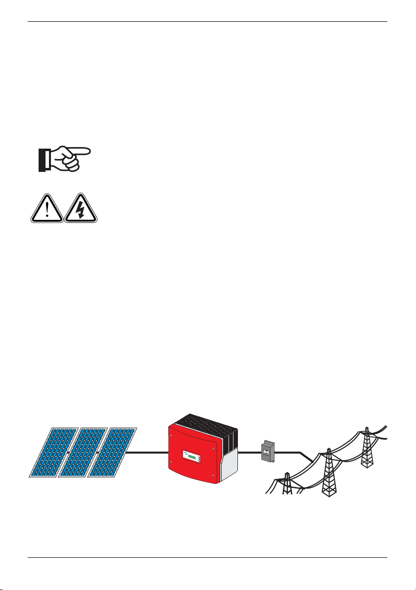
In general, the SB3800U takes power from a DC source (PV modules) and converts it to
AC power for the utility grid. This power is delivered first to local loads (household
appliances, lights, motor loads, etc.), with any excess power fed to the utility. The power
consumed by the local loads reduces the power needed from the utility. Excess power
may actually “spin the utility meter backwards” depending on the type of meter in your
system. This power may also be recorded as power credits by the utility company
depending on the interconnection agreement. An example of basic system components
is shown in
Figure 1-1.
Meter
B
e
t
r
i
e
b
O
p
e
r
a
t
i
o
n
E
r
d
s
c
h
lu
E
s
a
s
r
t
h
F
a
u
l
t
S
t
ö
r
u
n
g
Fa
il
u
r
e
PVArray
Sunny Boy 3800U
Utility Grid
Figure 1-1 SB3800U Installed in a Utility Interactive PV System
SB3800U-12:SE2006 SMA America 1-1
Page 10
Note: Policies vary from one utility company to another. Consult
with a representative of the local utility company before
designing and installing a PV system.
Safety
Anti-Islanding Protection
Islanding is a condition that can occur if the utility grid is disconnected while the
SB3800U is operating and the remaining load is resonant at 60 Hz and matches the
output of the SB3800U perfectly. This condition is highly unlikely and had never been
witnessed outside of a controlled laboratory. Nevertheless, the SB3800U incorporates
an advanced active islanding protection algorithm to insure that the system will not
export power into a balanced 60 Hz resonant load while the utility is disconnected. The
SB3800U periodically injects both leading and lagging reactive current into the utility
grid. This method has been proven by U.S. regulatory agencies to effectively destabilize
and disconnect from a balanced island condition.
PV Ground Fault Detection and Interruption
The SB3800U is equipped with a ground fault detection device. If a ground fault current
greater than 1 Amp is detected, the SB3800U will shut down and display the fault
condition on the user interface display. Once the ground fault is located and corrected,
the ground fault error will need to be manually cleared and the inverter will then resume
normal operation.
PV Series Fusing
Series fusing may be required depending on the type of PV module used in the system.
See NEC 690.9
Interconnection Code Compliance
The SB3800U has been tested and certified by ETL to meet the requirements of UL1741
Static Inverters and Charge Controllers for use in Photovoltaic Power Systems as well
as IEEE-929-2000 Recommended Practice for Utility Interface of Photovoltaic Systems
and IEEE 519 Standard Practices and Requirements for Harmonic Control in Electrical
Power Systems. The SB3800U is also ETL listed under UL1741 for use in Canada.
1-2 SMA America SB3800U-12:SE2006
Page 11
UL1741 is the standard applied by ETL to the Sunny Boy 3800U
to certify that it meets the requirements of the NEC and IEEE-929-
2000. IEEE 929-2000 provides recommendations regarding the
proper equipment and functionality necessary to ensure
compatible operation when power generation is connected to the
utility grid.
Note: Contact the local utility and/or the authority having
jurisdiction prior to connecting the SB3800U to the utility grid.
FCC Compliance
The SB3800U has been tested and certified by a nationally recognized testing
laboratory and conforms to all FCC Part 15 B EMI/EMC emissions regulations.
Feature Overview
Over twenty years of inverter manufacturing experience has gone into the design of the
SB3800U. As a result, the SB3800U represents state-of-the-art technology, high
reliability and overall ease of use - all the qualities you’ve come to expect from SMA,
the industry leader in inverter technology. Some of the features included are:
•LCD
• Temperature regulated fan cooling - simple replacement
• Auto line voltage detection and configuration
• Advanced communication options available
• Compatible with all SMA inverter and communication products
• High efficiency
• Simple installation
• Powder coated diecast enclosure
Operating Temperature
The SB3800U has been designed to maintain full power output with ambient
temperatures as high as 45°C. Fan cooling allows this level of output power to be
achieved even in enclosed spaces. The SB3800U will continue to operate well beyond
45°C and derates as needed to maintain a safe internal component temperature.
SB3800U-12:SE2006 SMA America 1-3
Page 12

Installation Overview
This section provides a high-level overview of the installation process so you have an
idea what to expect as you proceed through the rest of the Installation Guide.
The installation process is broken down into the following tasks:
Section 2: Unpacking and Inspection
This section provides instructions and information for unpacking the SB3800U and
inspecting it for shipping damage.
Section 3: Mounting
This section includes guidelines to help you select the best mounting location,
suggestions to insure optimum performance, cautions and warnings that you should
follow to avoid injury and/or equipment damage and step-by-step instructions for
mounting the SB3800U inverter.
Section 4: Input Voltage Configuration
This section includes information on removing the cover, locating primary components
within the inverter and selecting the appropriate voltage configuration for the
installation.
Section 5: Wiring the Sunny Boy 3800U
This section includes guidelines for selecting the correct wire sizes, cautions and
warnings that you should follow to avoid injury and/or equipment damage and stepby-step instructions for wiring the SB3800U to a PV array, household electrical circuits
and the utility grid. Procedures are also included for connecting optional datacommunication cables.
Section 6: Commissioning
Commissioning involves applying DC input power to the SB3800U, observing the LED
and LCD indicators on the front cover, and resolving any problems that occur.
Section 7: Displays and Messages
This section provides troubleshooting tips and procedures for resolving problems that
may occur during installation and operation.
1-4 SMA America SB3800U-12:SE2006
Page 13
Section 2:
Unpacking and Inspection
All Sunny Boy inverters are thoroughly tested and inspected before they are packed and
shipped. Although they are shipped in sturdy, recyclable packaging; damage can still
occur during shipping. It is important to carefully inspect the shipping container prior to
beginning the installation. If any external damage to the packaging makes you suspect
the inverter itself could be damaged, or if you find that the inverter is damaged after
unpacking it, report the damage immediately to your SMA dealer and to the shipping
company that delivered the Sunny Boy. If it becomes necessary to return the Sunny Boy,
use the original packaging in which it was delivered.
WARNING: The Sunny Boy 3800U weighs 85 lb. (38 kg). To
avoid injury, be sure to use proper lifting techniques and secure the help of someone to assist in the unpacking and installation of the inverter.
If you need assistance with a damaged Sunny Boy, contact your SMA dealer or SMA
America. Contact information for SMA America is provided below.
SMA America, Incorporated
12438 Loma Rica Drive
Grass Valley, California 95945
Tel 530.273.4895
Fax 530.274.7271
www.sma-america.com
SB3800U-12:SE2006 SMA America 2-1
Page 14

2-2 SMA America SB3800U-12:SE2006
Page 15
Section 3:
Mounting
This section provides guidelines to help you select the best mounting location,
suggestions to insure optimum performance, cautions and warnings that you should
follow to avoid injury and/or equipment damage, and step-by-step instructions for
mounting a SB3800U inverter.
WARNING: The SB3800U weighs 85 lb. (38 kg). To avoid injury, be sure to use proper lifting techniques and secure the
help of someone to assist in the unpacking and installation of
the inverter.
Note: Occasionally, the rating label on the SB3800U will need
to be referred to. For this reason, it is required that the inverter
be mounted so that the rating label on the side of the inverter be
visible.
Choosing a Mounting Location
Consider the following guidelines, cautions, and warnings when choosing a mounting
location for the SB3800U:
• Do not install the SB3800U in direct sunlight. External heating from exposure to the
sun may cause excessive internal heating. This can result in derated output power to
protect the internal components from damage.
• Install the SB3800U in a location that maintains an ambient air temperature that is
less than 45°C. To maintain a safe internal component temperature, the SB3800U
may reduce its power output if the ambient air temperature exceeds 45°C. (The
cooler the air temperature, the longer the life expectancy of any power electronics
device.)
• The SB3800U is constructed in a rugged powder coated aluminium enclosure
designed for outdoor installations. However, care should always be taken to
minimize exposure to the elements. It is best to minimize exposure to rain, snow and
ice, etc. Do not install the SB3800U in a location exposed to sources of direct water
spray such as sprinklers or downspouts.
• The inverter should be installed in a location that is inaccessible to children.
• The SB3800U may emit a slight vibrating noise when operating. This vibration is
normal and has no effect on performance, but it may be noticeable if the inverter is
mounted on a wall in a living area, on the outside of a wall that is near a living area,
or on certain types of materials, such as thin wood panelling or sheet metal.
SB3800U-12:SE2006 SMA America 3-1
Page 16
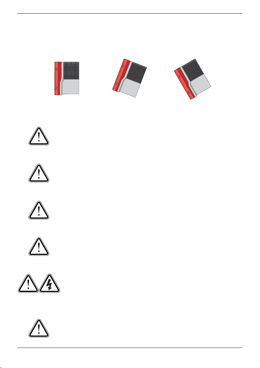
• If the inverter is installed outside, it should be mounted vertically or tilted back. (See
Figure 3-1).
Vertical
(Best option)
Tilted Back
(Acceptable)
Figure 3-1 Sunny Boy Mounting Positions
CAUTION: The SB3800U weighs 85 lb. (38 kg.). Ensure
that the mounting surface is strong enough to hold the
weight of the SB3800U. Do not mount the Sunny Boy on
plasterboard (sheet-rock) or thin wood panelling.
CAUTION: All electrical conduits and any communication
cables must be positioned and/or sealed so that no water
can enter the inverter enclosure through these conduits and
cables.
CAUTION: Do not install the SB3800U during periods of
precipitation or high humidity (>95%). Moisture trapped
within the enclosure may cause corrosion and damage to
the electronic components.
Tilted Forward
(Unacceptable)
CAUTION: If you are installing the Sunny Boy in a cabinet,
closet, or other relatively small enclosed area, you must provide sufficient air circulation to dissipate the heat generated
by the inverter.
WARNING: To prevent electrical shock or other injury,
check for existing electrical or plumbing installations in the
walls before drilling mounting holes for the Sunny Boy.
CAUTION: Outdoor installations must use raintight or wet
location hubs that meet the requirements of the Standard for
Fittings for Cable and Conduit, UL514B.
3-2 SMA America SB3800U-12:SE2006
Page 17
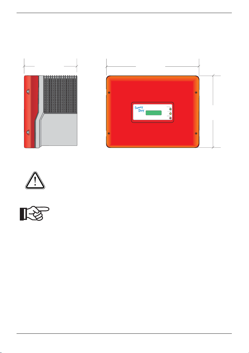
Dimensions and Recommended Clearances
The outer dimensions of the SB3800U are shown in Figure 3-2. The SB3800U must be
mounted so that there is at least eight inches of clearance around it.
236 mm
(9.3 in)
Figure 3-2 Outer Dimensions of the SB3800U
CAUTION: You must ensure that there is sufficient clearance for
the flow of the air around the SB3800U! In a normal operating
environment with good ventilation, eight inches of clearance is
adequate.
Note: The National Electrical Code may require significantly
larger working clearances (see NEC Section 110.26).
452 mm
(17.80 in)
Betrieb
Operation
Erdschluss
Earth Fault
Störung
Failure
351 mm
(13.83 in)
SB3800U-12:SE2006 SMA America 3-3
Page 18
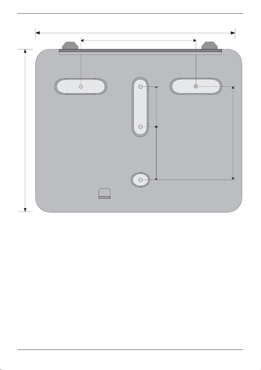
434,60 mm (17,12 in)
250 mm (9,85 in)
75 mm (2,95 in)
349,3 mm (13,76 in)
Figure 3-3 Dimensions of the Wall Mounting Bracket
178,9 mm (7,05 in)
104 mm (4,09 in)
3-4 SMA America SB3800U-12:SE2006
Page 19
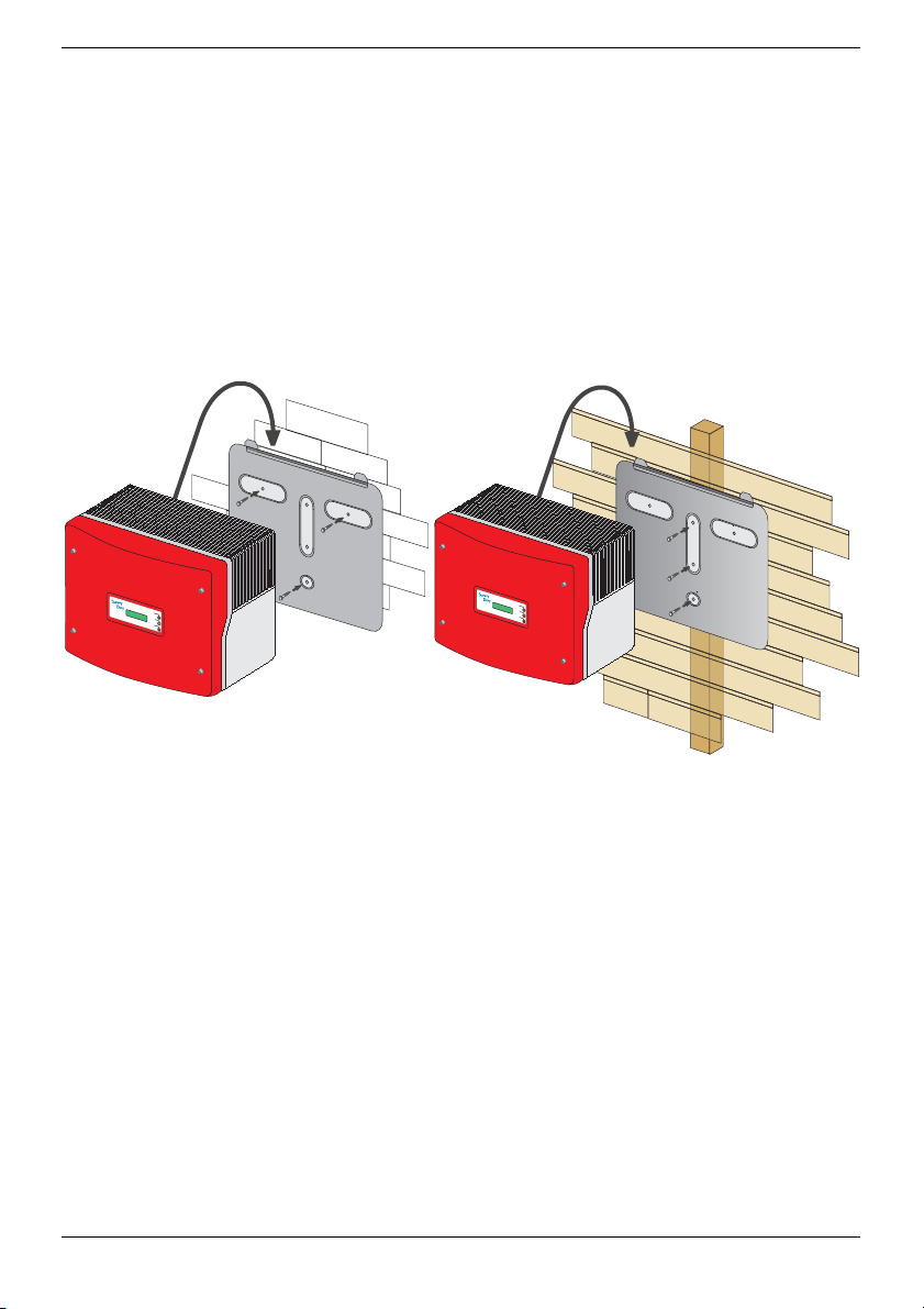
Mounting Procedure
The SB3800U is shipped with a removable mounting plate. This plate is also the wallmounting bracket suitable for use on most material (see
holes for mounting to wooden stud wall panels. Make sure that the wall you choose to
mount the Sunny Boy on is sturdy enough to support the weight (38 kg/85 lb.) and that
the wall is plumb. The bracket may also be mounted on stone, brick or solid walls. Be
sure to use the appropriate type of mounting hardware for the wall material and ensure
that the hardware is no smaller than 1/4” diameter.
Figure 3-4). The plate has three
Stone wall mounting
B
etrie
b
O
pe
ration
Erdschlus
Ea
s
B
e
tr
ie
b
O
p
e
r
a
ti
o
n
E
r
d
s
c
h
l
u
E
s
a
s
r
t
h
F
a
u
l
t
S
t
ö
r
u
n
g
Fa
i
l
u
r
e
r
th Fault
Störung
Failure
Figure 3-4 SB3800U with removable mounting plate
Wood wall mounting
SB3800U-12:SE2006 SMA America 3-5
Page 20
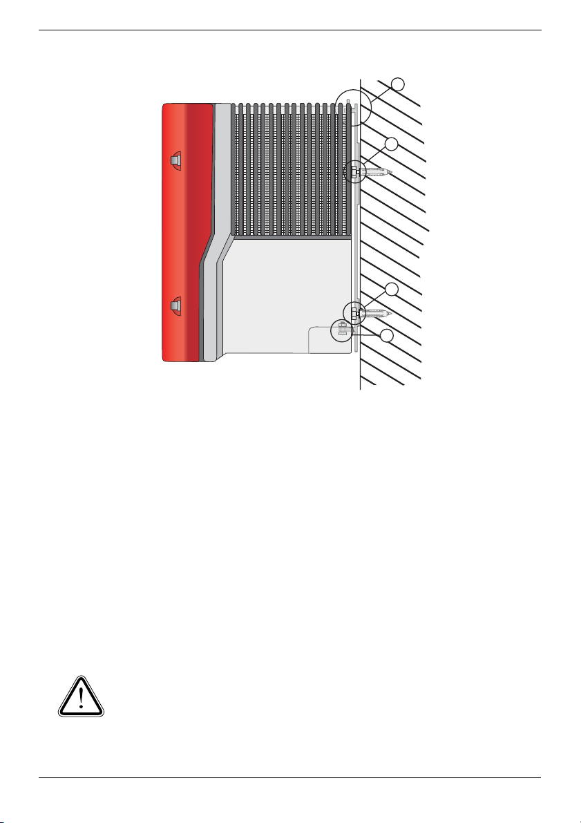
2
1
1
3
Figure 3-5 Mounting the SB3800U
Use the following procedure to mount the SB3800U:
1. Locate the mounting plate included in the shipping container with the SB3800U.
2. The holes in the mounting plate are sealed with plastic plugs. Remove the plastic
plugs for only the holes used.
3. Position the mounting plate against the wall where you intend to mount the
SB3800U. (Try to mount the SB3800U so that the display is approximately at eyelevel.) Place a level on the top edge of the mounting plate, and adjust the position of
the mounting plate until it is level. The bottom of the mounting plate will be equal to
the approximate location of the bottom of the inverter.
4. Using the mounting plate as a template, mark the wall through three holes in the
mounting plate. (See Figure 3-4)
CAUTION: Ensure that there are studs in the wall at the places where
you intend to drill the mounting-holes. DO NOT use molly or toggle bolts
to mount the SB3800U to sheet rock or panelling.
5. Set the mounting plate aside temporarily, and drill holes at the marks on the wall.
3-6 SMA America SB3800U-12:SE2006
Page 21
Note: The diameter of the holes you drill must match the hardware you
are using to mount the SB3800U. For example, if you are mounting the
SB3800U to a concrete wall, the hole diameter should be approximately
the same as the outside diameter of the concrete anchors you intend to
use. If you are mounting the SB3800U on a wall that has wooden studs
inside it, the hole diameter should be the correct size for the lag screws
you intend to use to mount the plate. If you are installing the SB3800U
outside, it is recommended that the lag screws be made of stainless steel,
and the diameter of the screws closely match the diameter of the holes
in the mounting plate. Make sure that the screws are long enough to
penetrate the wall to a depth of 1 and 1/2 inches.
6. Insert the screws through the holes in the mounting plate and into the holes you
drilled in the wall. Tighten the screws until the mounting plate is held firmly against
the wall. Do not overtighten the screws.
WARNING: The SB3800U weighs 85 lb. (38 kg). To avoid injury, be
sure to use proper lifting techniques and assistance in the unpacking
and installation of the inverter.
7. Carefully lift the SB3800U onto the mounting bracket. There are two small slots in
the top of the SB3800U. These slots sit on the pair of tabs on the top edge of the
mounting plate. Mount the SB3800U so that it hangs on these tabs. (see #2 in Figure 3-5).
8. Inspect the SB3800U from both sides to ensure that the channels on the back of the
SB3800U sit completely on the tabs on the top edge of the mounting bracket and
that the SB3800U is centered on the bracket.
9. Insert the hex screw and lock washer (included in the accessories package) in the
hole in the bottom of the SB3800U (#3 in Figure 3-5).
10.Tighten the screw to 44 inch pounds or 5 Nm. (Do not overtighten)
11.Verify that the SB3800U is securely mounted.
12.Snap the left and right exhaust fins into the SB3800U (Look for the L & R on the
inside of the fins.)
SB3800U-12:SE2006 SMA America 3-7
Page 22

3-8 SMA America SB3800U-12:SE2006
Page 23
Section 4:
AC Voltage Configuration
Opening the Sunny Boy 3800U
Remove the four screws and lock washers that attach the cover of the SB3800U. Place
the cover, screws, and lock washers aside where they will be out of your way while
connecting the wires and cables to the Sunny Boy.
CAUTION: Be careful not to misplace the screws or the lock
washers, as all four screws and lock washers are required to
ensure that the cover is grounded properly and is fully sealed
to the case. Handle the cover carefully, as even minor damage
to the cover could result in an inadequate seal between the
cover and the case, thus allowing moisture to enter the case
and damage the sensitive electronic components.
CAUTION: Do not install the SB3800U during periods of
precipitation or high humidity (>95%). Moisture trapped within
the enclosure may cause corrosion and damage to the electronic components.
SB3800U-12:SE2006 SMA America 4-1
Page 24
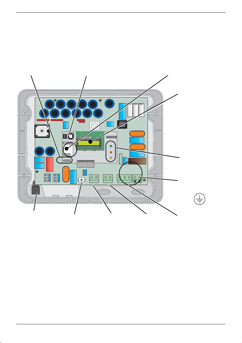
Locating Internal Components
Figure 4-1 illustrates the locations of the major internal components of the SB3800U.
Refer to this illustration as needed to locate particular components.
Terminal for optional
communication
(RS-232 or RS-485)
GFDI
Fuse Holder
Terminals (PE) for
Communication
Firmware EEPROM
Ground
++
(input from
PV array)
--
DC+
Terminal
L1
Sockets for optional
communication Piggy-Back
(RS-232, RS-485, powerline or radio)
Display
Status LEDs
L2 N
Ground
Terminal (PE)
DC–
Terminal
(input from
Output AC Line
Terminals
(N, L1 and L2)
PV array)
Figure 4-1 SB3800U Internal Components
4-2 SMA America SB3800U-12:SE2006
Page 25

Utility Configuration Jumpers
The SB3800U comes from the factory pre-configured for utility interconnection with
neutral. The SB3800U may be reconfigured for grids without neutral by setting the
jumpers on the board of the SB3800U.
The utility configuration jumpers allow the SB3800U to be connected to transformers
where the neutral is not present, such as the 208V and 240V Delta, shown in
Figure 4-
3. Refer to the figure below for a description of jumper settings.
Display
240 / 208 VAC (Default) (With Neutral)
208V Delta, No Neutral.
240V Delta, No Neutral.
Fan Test.
Figure 4-2 Utility Configuration Jumpers
The SB3800U may be configured for two different grid types commonly found in the
U.S. The SB3800U is compatible with:
• 208 V AC output
• 240 V AC output ("split-phase" or open delta)
SB3800U-12:SE2006 SMA America 4-3
Page 26
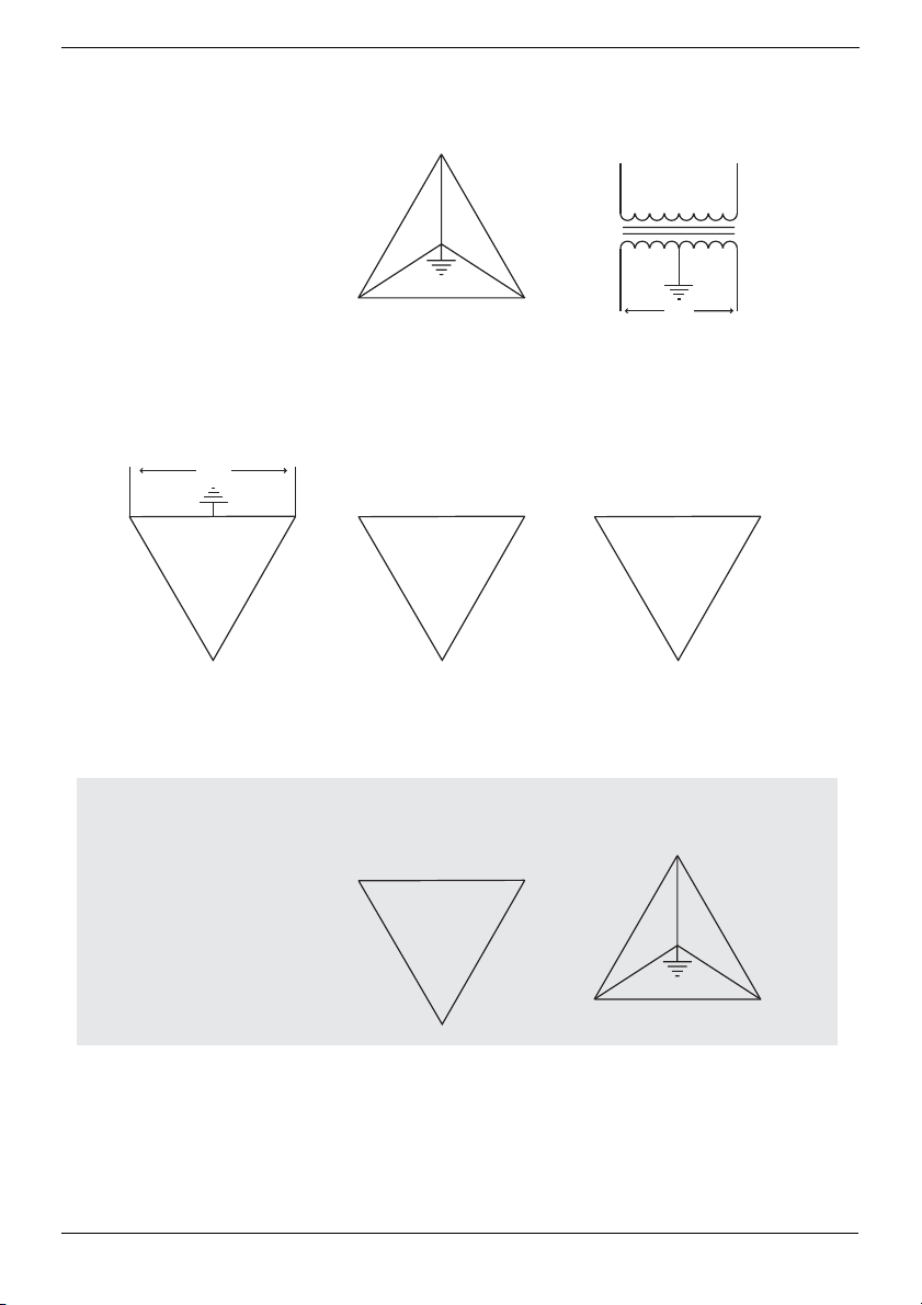
$ELTA79%
3PLIT0HASE
4HESECONFIGURATIONS
ARECOMPATIBLEWITHTHE
3UNNY"OY5
$ELTA3TINGER
$ELTA
$ELTA
$/./453%
$ELTA79%
.EUTRAL
$ELTA
$/./453%
4HESECONFIGURATIONS
ARE./4COMPATIBLEWITHTHE
3UNNY"OY5
Figure 4-3 Common Utility Voltage Configurations
Remember, when connecting the SB3800U to the utility, the phase relationship is not
important, but the voltage must be compatible.
4-4 SMA America SB3800U-12:SE2006
Page 27

240 Delta : 120 Stinger
Inverter 3
Jumper Settings
240 V
Jumper Settings
Inverter 2
120 V
240 V
120 V
240 V
Inverter 1
Jumper Settings
Figure 4-4 Utility Configuration Jumper Examples
The figure above illustrates the proper jumper settings when connecting to a 240 Delta :
120V Stinger type transformer. Note the order in which inverters are connected to the
phases.
SB3800U-12:SE2006 SMA America 4-5
Page 28

4-6 SMA America SB3800U-12:SE2006
Page 29

Section 5:
Wiring the Sunny Boy 3800U
This section provides step-by-step procedures and other information required for wiring
the SB3800U to the PV array and the utility grid. To complete the installation in a safe
and efficient manner, complete the steps in the order that they appear.
WARNING: Before connecting or operating the SB3800U,
read all of the instructions, cautions, and warnings on the
SB3800U, the PV array and in this Installation Guide.
WARNING: You must connect the wires that carry the AC
voltage from the SB3800U to the utility grid and the wires
that carry the DC voltage from the PV array to the
SB3800U in the order described in the procedures in this
section. Deviating from these procedures could expose
you to lethal voltage that can cause serious injury.
WARNING: Always turn OFF all breakers and switches in
the PV system before connecting any wires to or
disconnecting any wires from the SB3800U.
WARNING: Always connect the wires to the SB3800U in
the following sequence:
1. De-energize all energy sources by opening all AC and DC disconnects and/or
breakers.
2. Connect wires from the AC breaker to the AC disconnect switch.
3. Connect wires from the AC disconnect to the SB3800U.
4. Connect the PV wires to the DC disconnect.
5. Connect the DC disconnect wires to the SB3800U·
6. Turn the AC switches and/or breakers ON.
7. Turn the DC switches and/or breakers ON.
To disconnect the SB3800U, first turn OFF all AC disconnects and then all DC
disconnects. The AC system should always be disconnected before the DC
SB3800U-12:SE2006 SMA America 5-1
Page 30

system. After the SB3800U is de-energized, disconnect the wiring in the
reverse order from above.
WARNING: Always wait a minimum of 5 minutes for
stored potentials in the SB3800U to discharge completely
before opening the enclosure.
WARNING: All electrical installations must be done in
accordance with all local electrical codes and the National
Electrical Code (NEC), ANSI/NFPA 70.
WARNING: Before connecting the SB3800U to the
electrical utility grid, contact the local utility company. This
connection must be made only by qualified personnel.
The internal AC and DC wiring terminals (see Figure 5-3) accept a maximum wire size
of #6 AWG. Knockouts are provided on the bottom of the SB3800U near each of the
terminals for the wires to enter the case (see Figure 5-6).
GFDI Fuse
1/2” Communication Cable
Gland
3/4” DC Knockout
3/4” AC Knockout
Figure 5-1 SB3800U showing wiring knockout locations
5-2 SMA America SB3800U-12:SE2006
Page 31

CAUTION: The AC and DC knockouts in the SB3800U chassis
are sized for 3/4-inch rigid conduit (EMT). DO NOT enlarge
any of these holes, as this is may violate the listing and will void
the SMA warranty.
Terminal in. lbs. nm.
AC & DC Terminal Blocks 18 2
Cover Screws 79 9
Wiring the AC Output
This subsection provides complete, step-by-step procedures for wiring the AC output
from the SB3800U to the utility grid.
AC Connection Requirements
WARNING: All electrical installations must be done in
accordance with all local electrical codes and with the
National Electrical Code (NEC), ANSI/NFPA 70. Use
#8 AWG (maximum), 90 °C (194 °F), copper wire for all
AC wiring connections to the Sunny Boy 3800U. Voltage
drop and other considerations may dictate that larger size
wires be used.
WARNING: The National Electrical Code (NEC) states that
the inverter must be connected to a dedicated circuit, and
that no other outlets or devices can be connected to the
same circuit. See NEC Section 690-64(b)(1). The NEC also
imposes limitations on the size of the inverter and the
manner in which it is connected to the utility grid. See NEC
Section 690-64(b)(2).
The diagram in Figure 5-2 shows the potential losses in AC wires with respect to the
cross-sectional area of the cable and the length of the cable. Use the following tables to
determine the best wire size to use for your particular installation.
SB3800U-12:SE2006 SMA America 5-3
Page 32

Percent voltage drop for 208 V AC and 240 V AC service
2,0%
12 AWG
1,6%
10 AWG
8 AWG
1,2%
0,8%
0,4%
6 AWG
Percent of 208 V AC and 240 V AC
0,0%
20 40 80 120 160 200 240
60 1000 140 180 220
One way distance (feet)
Figure 5-2 Energy Losses in Various Wire Sizes and Wire Lengths
The SB3800U is designed to automatically detect which grid voltage it is feeding if a
neutral is connected to the inverter. Depending upon the voltage and phase angle
between L1-N and L2-N, the inverter will determine if it is connected to a 208 V or 240
V grid.
Table 5-1 Voltage and Frequency Limits for the AC Connection
Table 5-1 lists the voltage and frequency limits for the AC connection.
Voltage Range for 208 V nominal, line to line 183 V - 229 V
Voltage Range for 240 V nominal, line to line 211 V - 264 V
Frequency Range 59.3 Hz - 60.5 Hz
5-4 SMA America SB3800U-12:SE2006
Page 33

Connecting the AC Wires
Use the following procedure to connect the AC wires to the SB3800U:
WARNING: You must connect the wires that carry the AC
voltage from the SB3800U to the utility grid in the order
described in this procedure. Deviating from this procedure
could expose you to lethal voltages that can cause serious
injury and/or death.
1. Turn OFF the main breaker in the main utility breaker panel.
2. Remove interior breaker panel cover.
3. If you are replacing an existing inverter, disconnect the wires for the AC line you
are working with in the breaker box.
4. Install a 3/4-inch conduit fitting in the SB3800U’s AC wiring knockout (the
knockout on the right side of the SB3800U, as shown in Figure 5-1). Fasten the
conduit fitting on the inside of the SB3800U with the appropriate locknut.
5. Install 3/4-inch conduit between the main breaker panel and the SB3800U’s AC
wiring knockout.
6. Pull the AC wires through the conduit from the interior of the breaker panel to the
interior of the SB3800U.
Note: Refer to Figure 5-4 on page 5-7 for steps 7 through 10.
CAUTION: Avoid using wire nuts to join any wires together or
to make any connections anywhere in the PV system. Wire nuts
are a frequent cause of unreliable, resistive connections, and
ground faults.
7. Connect the AC equipment-ground wire to the terminal labeled PE in the
SB3800U.
8. Connect the L1 (AC line 1or HOT) wire to the terminal labeled L1 in the SB3800U.
9. Connect the L2 (AC line 2) and N (AC line N) wire to the terminal labeled L2 and
N in the SB3800U.
10. Connect the wires and tighten to a torque of 18 in-lb.
11. Verify that all connections are correctly wired and properly torqued.
SB3800U-12:SE2006 SMA America 5-5
Page 34

N wire connected to N terminal
L2 wire connected to L2 terminal
L1 wire connected to L1 terminal
Figure 5-3 AC Connection Terminals
--
++
Equipment ground wire
connected to PE terminal
L2 N
L1
5-6 SMA America SB3800U-12:SE2006
Page 35

Wiring the DC Input
This subsection provides procedures for wiring the DC input from the PV array (via the
DC disconnect enclosure) to the SB3800U.
diagram of a PV system.
Figure 5-4 shows a simplified wiring
600 V DC
DC-breaker and
combiner box
Betrieb
Operation
Erdschluss
Earth Fault
Störung
Failure
Figure 5-4 Simplified Electrical Wiring Diagram of a PV System
DC Connection Requirements
WARNING: All electrical installations must be done in
accordance with all local electrical codes and with all local
electrical codes and with the National Electrical Code
(NEC), ANSI/NFPA 70. For installation in Canada the
installations must be done in accordance with applicable
Canadian standards. Use #10AWG (minimum), 90 degC,
copper wire for all DC wiring connections to the Sunny
Boy. Voltage drop an other considerations may dictate
that larger size wires be used.
Note: Use the online SMA string size calculator at
www.sma-america.com to determine the correct string
configuration (see Figure 5-5).
208 or 240 V AC
60 Hz System
via Approved
Disconnect
Note: Series fusing may be required depending on the type
of PV module used in the system. See NEC 690.9.
SB3800U-12:SE2006 SMA America 5-7
Page 36

Figure 5-5 Online String-Configuration Calculator at www.sma-america.com
5-8 SMA America SB3800U-12:SE2006
Page 37

Connecting the DC Wires
WARNING: You must connect the wires that carry the DC
voltage from the PV array to the Sunny Boy 3800U in the
order described in the following procedure. Deviating
from this procedure could expose you to lethal voltages
that can cause serious injury and/or death.
WARNING: PV arrays are energized when exposed to
light. Use safe working practices when working on PV
arrays.
WARNING: Always turn OFF all AC and DC breakers and
switches in the PV system and wait a minimum of 5
minutes for the SB3800U to completely discharge before
connecting any wires to the SB3800U or disconnecting
any wires from the SB3800U. Failure to do so could
expose you to lethal voltages that can cause serious injury
and/or death.
CAUTION: Verify the polarity and the open-circuit voltage
from the PV strings before you connect the DC wires to the
SB3800U. Applying an open-circuit DC-input voltage that
exceeds the maximum DC-input-voltage range will cause
irreversible damage to the SB3800U and void the
warranty! Always verify the DC voltage before connecting
the DC-input wires from the PV array to the SB3800U. (See
the online SMA string size calculator at www.smaamerica.com to determine the correct string configuration
as shown in Figure 5-5.)
SB3800U-12:SE2006 SMA America 5-9
Page 38

Check both the polarity
and the open-circuit
voltage from the PV strings!
Use the following procedure to connect the DC wires to the Sunny Boy 3800U:
1. Verify that the AC breaker is OFF.
2. Verify that the DC disconnect is OFF.
3. Install a 3/4-inch conduit fitting in the SB3800U’s DC wiring knockout. (See Figure
5-1and Figure 5-6). Fasten the conduit fitting on the inside of the SB3800U with
the appropriate locknut.
4. Install 3/4-inch conduit between the DC disconnect enclosure and the SB3800U’s
DC wiring knockout.
Note: Refer to Figure 5-6 for steps 5 through 7.
Positive DC wire connected to DC+ terminal
Negative DC wire
connected to DC- terminal
Figure 5-6 DC Connection Terminals
5-10 SMA America SB3800U-12:SE2006
Page 39

5. Pull the DC wires from the DC disconnect through the conduit into the interior of the
SB3800U.
6. Connect the positive DC wire to the terminal labeled DC+ in the SB3800U.
7. Connect the negative DC wire to the terminal labeled DC– in the SB3800U.
Note: The SB3800U has provisions for up to two PV strings.
The positive and negative terminal blocks each have two
positions, so two pairs of DC-input wires can be connected
in parallel.
CAUTION: Avoid using wire nuts to join any wires together
or to make any connections anywhere in the PV system.
Wire nuts are a frequent cause of unreliable connections,
resistive connections, and ground faults.
8. Connect the positive and negative DC wires to the appropriate terminals in the DC
disconnect enclosure.
9. Connect the DC equipment ground wire to the terminal labeled PE in the SB3800U.
10. Torque all AC and DC wires in the SB3800U to 18 in-lb.
11. Verify that all connections are correctly wired and properly torqued.
SB3800U-12:SE2006 SMA America 5-11
Page 40

Connecting Communication Cables
Various data-communication options are available for the SB3800U. These options are
provided in the form of accessory Piggy-Back modules that can be installed and
connected either at the time the inverter is installed or at any time thereafter. These
modules are not included with the SB3800U. Please contact SMA America for
information. Refer to the instructions included with the communication module for
installation procedures.
The following subsections provide instructions for connecting the various communication
cables between a SB3800U with a communication module and a personal computer
(PC). The connection of a SB3800U to a Sunny Boy Control or a Sunny Beam wireless
monitoring unit is shown in those respective manuals.
RS-232 Communication
RS-232 is a communication standard for bidirectional transmission of data between a
Sunny Boy and a PC. Only one Sunny Boy can be connected with an RS-232 serial cable
to a PC.
Requirements for RS-232 Communication:
• The SB3800U must be equipped with an RS-232 Piggy-Back communication module.
• The cable should be no longer than 15 meters (50 ft.) Use the cable type specified
in the RS-232 Tech Note on www.sma-america.com.
• RS-232 cables are available from SMA America.
• Conduit may be required for communication wiring, per local electrical code requirements.
Connecting an RS-232 Cable
Use the following procedure to install an RS-232 data-communication network:
1. Run the communication cable from the location of the PC to the SB3800U.
2. Verify that the PC has a serial port and that it is activated in the BIOS and the
operating system.
3. Attach the appropriate DB-9 connector to the end of the cable near the PC. See
Table 5-2 and Figure 5-7 for the pin assignments for the serial connector. Record
the wire color used for each of the pins listed in Table 5-2.
4. Route the other end of the cable into the SB3800U through the communication-
knockout on the bottom left of the SB3800U (see Figure 5-1).
5-12 SMA America SB3800U-12:SE2006
Page 41

5. Referring to Table 5-2 and Figure 5-7 and your record of the wire colors used for
each pin from step 3, connect the appropriate wires to the communication terminal
block in the SB3800U.
6. Connect the cable shield to the SB3800U’s case. (See Figure 5-7) Do NOT connect
the cable shield to the PC’s DB-9 connector. The shield must remain floating at the
PC.
CAUTION: All AC and DC power should be off when
connecting the communication wiring to the SB3800U.
SB3800U-12:SE2006 SMA America 5-13
Page 42

Table 5-2 RS-232 Pin Assignments
Communication Terminal
Block (SB3800U)
Case Shield Case Case
2 RxD
3 TxD
5 GND 5 7
B
e
tr
i
e
b
O
p
e
r
at
io
n
E
r
d
s
c
h
l
u
E
s
a
s
r
t
h
F
a
u
l
t
S
t
ˆ
r
u
n
g
F
a
i
l
u
r
e
Signal Name
(Output from
Sunny Boy)
(Input to Sunny
Boy)
5
3
2
9-Pin Serial-Port
25-pin Serial-Port
Connector (PC)
2 3
3 2
PC running
Sunny Data
5
3
2
RS-232 Piggy-Back
communication module
No jumper installed for
RS-232 communication
Connector (PC)
Terminal block for
RS-232 communication
Ground terminal (PE)
C
B
A
2357
L2 N
--
L1
++
for communication
Figure 5-7 Connecting a SB3800U to a PC with an RS-232 Cable
5-14 SMA America SB3800U-12:SE2006
Page 43

RS-485 Communication
RS-485 is a communication standard for bidirectional transmission of data between one
or more Sunny Boy inverters and a PC.
Note: All Sunny Boy inverters are capable of RS-485
communication. You can mix different Sunny Boy models on the
RS-485 communication bus.
Requirements for RS-485 Communication:
• The Sunny Boy 3800U must be equipped with an RS-485 Piggy-Back communication module.
• The cable should be no longer than 1200 meters (4000 feet) with a common shield,
and a wire size no smaller than 24 AWG. Use the cable type specified in the RS485 Tech Note on www.sma-america.com.
• RS-485 cables are available from SMA America.
• Conduit may be required for communication wiring, per local electrical code requirements.
Connecting an RS-485 Cable
Use the following procedure to install an RS-485 data-communication network:
Note: The following steps describe how to connect one or
more Sunny Boy inverters to an RS-485 bus. For more
information on connecting more than one inverter to an RS485 bus, please see “Technical Note: RS-485
Communication” in the Tech Updates section of our web site
at www.sma-america.com
1. Connect the three wires of the RS-485 cable to terminals 2, 5, and 7 of the
communication terminal block as shown in Figure 5-8. Record the wire color used
for each of the terminals. Two communication knockouts are provided for
connecting multiple Sunny Boys on an RS-485 communication bus.
2. Connect the shield of the cable to the Sunny Boy 3800U’s case. (See Figure 5-8)
Do NOT connect the cable shield to the PC’s DB-9 connector. The shield must
remain floating at the PC.
3. Install a jumper in position A, the bottom set of pins on the communication jumper
block, to set it for termination. (See Figure 5-8)
SB3800U-12:SE2006 SMA America 5-15
Page 44

Note: The termination of the other end of the RS-485 cable
will depend on what type of device you’re connecting to. For
detailed information, please see the Tech Updates section of
our web site at www.sma-america.com There you will find
technical information on all of the Sunny Boy communication
options.
Jumper Configuration for RS-485 Communication:
RS-485 Piggy-Back
Communication Module
Signal Symmetry and
Termination Jumpers
Terminal Block for
RS-485 Connections
Jumpers B & C Installed:
Jumper A installed:
Installing these jumpers puts 680 Ohm
symmetry resistors between pin 2 (Data+)
and +5V and between pin 7 (Data-) and
Ground.
Installing this jumper puts a 120 Ohm
termination resistor across pin 2 (Data+)
and pin 7 (Data-).
C
B
A
2357
L2 N
L1
--
++
NOTE: Install jumpers B & C after the inverter is on
the RS-485 bus and only if symmetry of the
signal is required. (Symmetry is already
provided by the Sunny Boy Control products)
Install jumper A only, if the inverter is on one of
the ends of the RS-485 bus.
Figure 5-8 Detail of RS-485 Termination and Jumper Settings
5-16 SMA America SB3800U-12:SE2006
Page 45

RS-485 Pinouts
2 - A (+) (Data+)
7 - B (-) (Data-)
5 - SR (Signal Ref.)
Replacing the Cover
When you have finished connecting the AC-output wires, the DC-input wires, and the
communication cables, re-check all your connections to ensure that everything is in the
right place and that all connections and knockout fittings are secure and properly
torqued. Check all of the knockout fittings on the bottom of the SB3800U to ensure that
they provide a weather-tight seal.
WARNING: Never install the SB3800U during rain or very
damp conditions. Because the SB3800U has a rain proof
enclosure, you must be sure no moisture is trapped inside
the enclosure when securing the lid.
CAUTION:
washers that attach the cover to the case, as all four screws
and lock washers are required to ensure that the cover is
grounded properly and is fully sealed to the case. Handle
the cover carefully, as even minor damage to the cover
could result in an inadequate seal between the cover and
the case, thus allowing moisture to enter the case and
damage the sensitive electronic components.
Use the following procedure to replace the cover on the SB3800U:
1. Check wire routing to ensure that no wires can interfere with proper sealing of the
cover and that no pressure will be exerted on the connections when the cover is
replaced.
2. Locate the four screws and lock washers you removed to take the cover off the
SB3800U. Make sure you have all four screws and lock washers, as all of this
hardware is necessary to ensure proper grounding and a weather-tight seal.
3. Carefully position the cover on the front of the SB3800U so that the four holes in
the cover are aligned correctly with the four threaded holes in the case.
Note: Be sure when reinstalling the four screws that the lock
washers are installed correctly. The teeth of the washers
SB3800U-12:SE2006 SMA America 5-17
Be careful not to misplace the screws or the lock
Page 46

should face towards the LID.
4. While holding the cover in place, carefully insert the four screws with lock washers
through the holes in the cover into the threaded holes in the case and turn them
until they are finger-tight. Be careful not to cross-thread any of the screws. Do not
use power tools to start the screws.
5. Verify that the cover is in the correct position and that the seal is in place between
the case and the cover.
6. Tighten the cover screws to a torque of 79 lb-in. (9 nm.)
5-18 SMA America SB3800U-12:SE2006
Page 47

Section 6:
Commissioning
WARNING: Follow the steps in the commissioning procedure in the order they are presented. Deviating from
these procedures could expose you to lethal voltages that
can cause serious injury and/or death.
WARNING: never insert the GFDI fuse into the SB3800U
without the fuse holder base. Lethal voltage may still be
present and electric shock may result.
CAUTION: Follow the steps in the commissioning procedure in the order they are presented. Deviating from these
procedures could cause irreversible damage to the
SB3800U and void the warranty.
All Sunny Boy inverters have a sophisticated system for detecting and responding to PV
array ground faults as required by NEC Section 690.5. The PV array normally operates
in a grounded configuration. The array’s negative conductor is connected to the
grounding system inside the inverter as a part of the UL1741 Listed ground-fault
detection system. The GFDI protection is active whenever there is sufficient DC voltage
to turn on the LCD in the SB3800U.
To commission the SB3800U, follow these simple instructions:
1. Connect the grid voltage to the SB3800U by switching on the main AC circuit
breaker in the main utility panel.
2. Switch the DC disconnect to the on position. If there is sufficient sunlight available,
the Sunny Boy 3800U will enter the “Wait“ mode at this time and the green LED
will begin to blink.
3. If no AC faults are detected, the “Wait“ mode will end after approximately 20
seconds and the green LED will stop blinking, remain on and the SB3800U will
begin to operate normally. If an AC fault was registered, the SB3800U will wait 5
minutes prior to starting.
SB3800U-12:SE2006 SMA America 6-1
Page 48

Note: If there is a ground fault in the array, the „EarthCurrentMax“ error message will be displayed and the GFDI fuse may
clear. If this error message is encountered, switch off the DC and
AC disconnects to the SB3800U and troubleshoot the array.
Note: If there is adequate solar irradiation and the resulting PV
input voltage is sufficient, the SB3800U will automatically begin
feeding power to the utility grid.
Note: If the SB3800U is not operating as expected after the
commissioning procedure has been completed, refer to Section
7: Displays and Messages and to Section 8 for troubleshooting
assistance.
6-2 SMA America SB3800U-12:SE2006
Page 49

Displays and Messages
Section 7:
Displays and Messages
Each Sunny Boy inverter comes equipped with three LED status indicators. (Shown in
Figure 7.1) This allows the user to determine the operating mode of the inverter at a
glance. The basic definitions of the indicator lights are as follows:
The green LED indicates normal operation of the inverter.
The red LED indicates the status of the GFDI fuse, located in the holder on the underside
of the inverter. If this LED is lit, the GFDI fuse has cleared or is not present.
The yellow LED indicates that there is a fault of some kind, either inside the inverter or
somewhere in the PV system. The inverter will not operate until the fault has been
corrected. The different error codes and possible causes are described later in this
section and in Section 8: “Troubleshooting”.
The red and yellow LEDs combined indicate that the inverter has detected a ground
fault. The ground fault must be located and cleared and the inverter reset manually. The
inverter will not restart automatically after detecting a ground fault. The ground fault
may also clear the GFDI fuse.
Note: All GFDI faults are disabled in turbine mode.
SB3800U-12:SE2006 SMA America 7-1
Page 50

Displays and Messages
Figure 7-1 The Sunny Boy LED Status Indicator
Betrieb
Operation
Erdschluss
Earth Fault
Störung
Failure
7-2 SMA America SB3800U-12:SE2006
Page 51

Displays and Messages
LED Operation Indicators
Standby (Night)
All LEDs are off
The inverter is in standby mode because the DC input voltage is too low for operation
or no DC is connected.
Initialization
All LEDs are on
The inverter is initializing. The power from the array is sufficient to initialize control
power, but not yet powerful enough to begin normal operation. Data transmission is not
possible during initialization.
Occasionally, during inclement weather or low irradiation, the LEDs may all turn on at
once and then go off again. This indicates that the inverter is trying to initialize but the
power available from the array is not sufficient for normal operation. This is not a
malfunction.
SB3800U-12:SE2006 SMA America 7-3
Page 52

Displays and Messages
Starting
1s
Green LED blinks
3 times per second
The inverter has sufficient DC voltage to initialize its internal systems, but not enough to
begin normal operation. Typically, the calibration lasts less than 10 seconds and then
the inverter resumes normal operation. DC voltage must remain greater than the PV Start
Voltage setting for the period of the T-Start parameter setting. (See Section 8) The
inverter will also show this status if it has been manually set to STOP mode.
Waiting
1s
Green LED blinks
once per second
The inverter has determined that there is enough DC voltage to operate and is checking
the condition of the grid prior to connecting.
Note: If the inverter fails to connect to the utility grid 3 times
in a row, it will wait 10 minutes before the next attempt.
In case of a grid failure, the Sunny Boy will wait 5 minutes
before it tries to reconnect to the grid.
7-4 SMA America SB3800U-12:SE2006
Page 53

Displays and Messages
Normal Operation
Green LED is on
The inverter is feeding the utility grid in either “MPP”, “Constant Voltage” or “Turbine”
mode.
“MPP” Mode: The SB3800U adjusts the voltage and current from the PV array to obtain
the greatest PV output power.
“Constant Voltage” Mode: The voltage from the PV array has been set to a fixed value.
This value is set by using the Sunny Boy Control or the Sunny Data software. (The
parameter name is “V-Const”) This mode is typically used for fuel cell or micro-hydro
applications.
“Turbine” Mode: This mode is used for DC rectified motor sources with a dynamic
power curve (typically wind turbines). The user can set the magnitude and slope of the
curve to match a particular alternator.
Derating
1s
Green LED is shortly
off once per second
The SB3800U is designed to operate at full rated power up to 45°C ambient. The
inverter will continue to operate beyond 45°C and will derate as required to maintain
safe internal component temperatures. Unnecessary derating can also be caused by
blocked fan intakes. For this reason the fan intakes should be inspected often and
cleaned when necessary.
SB3800U-12:SE2006 SMA America 7-5
Page 54

Displays and Messages
LED Fault Indicators
Ground Fault
Red LED is on
Yellow LED is on
The inverter has detected a ground fault in the PV system and has disconnected from the
grid. The ground fault must be located and fixed before the inverter will resume
normal operation. The inverter will not restart automatically. Refer to Section 8:
“Troubleshooting” for information on solving PV array ground faults.
Note: All GFDI faults are disabled in turbine mode.
Cleared GFDI Fuse
Red LED is on
The GFDI fuse located in the fuse holder on the bottom of the inverter has been cleared
or is not present. This fuse is used to protect the PV system in the event of an array
ground fault. Troubleshoot the PV array for ground faults prior to replacing this fuse.
CAUTION: For continued protection against the risk of fire,
replace the GFDI fuse with fuses of the same type and rating
only. The SB3800U is shipped with a Littelfuse KLKD 1 Amp,
600V AC/DC type fuse.
7-6 SMA America SB3800U-12:SE2006
Page 55

Displays and Messages
Control System Fault
Yellow LED is
permanently on
The yellow LED remains lit.
The SB3800U has detected a fault within the internal monitoring systems. When the
inverter detects a fault of this kind it will no longer connect to the utility grid. To correct
this, the inverter must be serviced by a qualified service technician. Contact SMA
America for assistance.
SB3800U-12:SE2006 SMA America 7-7
Page 56

Displays and Messages
Grid Failure
Yellow LED blinks
shortly twice
LED on
LED off
5s
The signal is repeated 3 times and
then starts from the beginning.
3s 1s
The yellow LED is on for 5 seconds, out for 3 seconds and then blinks twice. The code is
repeated 3 times. This code sequence will repeat as long as there is a grid fault
condition.
This code can be caused by any of the following conditions:
• Low Grid Voltage (<Vac Min)
• High Grid Voltage (>Vac Max)
• Low Grid Frequency (< fac Min)
• High Grid Frequency (>fac Max)
• Rapid change in grid frequency or voltage
Check the condition of the grid at the AC terminal blocks within the SB3800U. Also
inspect the AC disconnect between the Sunny Boy and the grid.
CAUTION: Have the grid connection to the SB3800U checked
only by qualified personnel.
WARNING: If opening the SB3800U is required, do so
only after disconnecting all sources of power and waiting
at least 5 minutes.
7-8 SMA America SB3800U-12:SE2006
Page 57

Displays and Messages
High DC Input Voltage
The yellow LED is blinking
4 times in short intervals
LED an
LED aus
5s
3s 1s1s 1s 1s
The signal is repeated 3 times and
then starts from the beginning
The yellow LED is on for 5 seconds, remains off for 3 seconds and then blinks 4 times.
The code is repeated 3 times. If the condition remains the code will continue to be sent.
The inverter has detected a DC input voltage that is too high for safe operation.
WARNING: Disconnect the PV array from the SB3800U
immediately. High DC input voltage can permanently
damage the inverter. Have the input source checked by a
qualified technician.
WARNING: Always test the DC voltage at the DC
disconnect switch before energizing the SB3800U.
SB3800U-12:SE2006 SMA America 7-9
Page 58

Displays and Messages
Inverter Fault
The yellow LED is blinking
5 times in short intervals
LED an
LED aus
5s
3s 1s1s 1s 1s
The signal is repeated 3 times and
then starts from the beginning
The yellow LED is on for 5 seconds, remains off for 3 seconds and then blinks 5 times.
The code is repeated 3 times. If the condition remains the code will continue to be sent.
The inverter has encountered an internal fault that prohibits normal operation and will
most likely require servicing.
Contact SMA America for assistance.
7-10 SMA America SB3800U-12:SE2006
Page 59

Displays and Messages
Status Messages on the LCD
The SB3800U comes standard with the “Sunny Display“ LCD in the lid.
Betrieb
Operation
Erdschluss
E-today 3.86kWH
Earth Fault
Mode MPP
Störung
Failure
Figure 7-2 SB3800U LCD
Activation of the Backlight
The backlight is activated by knocking twice on the lid. Additional knocks will scroll
through the display messages.
The backlight shuts off automatically after 2 minutes.
INIT Messages
The following messages are displayed during initialization
of the inverter:
The installed firmware versions of the control system
processor (BFR) and the current regulator processor (SRR)
are displayed after 6 seconds.
SB3800U-12:SE2006 SMA America 7-11
Sunny Boy 3800U
WR38UxxE
Sunny Boy Inverter Model #
BFR Version x.xx
SRR Version x.xx
Firmware Version #’s
Page 60

Displays and Messages
Operation Messages
The LCD continuously scrolls through all relevant operating
data
. Each message (MSG) is displayed for 5 seconds,
after all messages have been displayed the LCD repeats
from the beginning.
MSG #1 “E-Today“ (total energy produced on this day) is
displayed together with the current operating mode:
E-today 3.86kWh
Mode MPP
Energy produced today
and current operating mode
MSG #2 Nominal grid voltage configuration and actual
line-to-neutral voltage measurements:
MSG #3 Actual AC power output and DC input:
MSG #4 Accumulated yield of the device since installation
and the total operating hours:
Note: The screens may also be scrolled through manually by
repeatedly knocking on the lid of the inverter. Each knock
advances the screen to the next message.
Gridtype - 208V
L1 120V L2 120V
Gridtype and phase-to-neutral
voltages
Pac 3200W
Vpv 380V
AC power
and DC voltage
E-total 724.4kWh
h-total 512h
Total energy yield
and total operating hours
7-12 SMA America SB3800U-12:SE2006
Page 61

Displays and Messages
Fault Messages
In case of a fault condition the LCD switches to “Fault“ mode and the backlight is
activated.
The upper display line indicates one of the three following failure types:
• Disturbance
For example, this Disturbance message would be displayed if the SB3800U detected a problem with the frequency of the utility grid. The message would clear
automatically once the condition was corrected. Distur-
Disturbance
Fac-Bfr
Disturbance Message
bances are typically caused by a measured value exceeding a predetermined limit, the frequency of the AC
grid for example. The display will show the value of the
error (at:) as well as the present value for the particular
parameter (present:).
at: 59.30Hz
present: 59.31Hz
Disturbance Details
• Warning
For example, this Warning message would be displayed
if the inverter detected a problem with the array voltage.
Typically, Warning messages indicate a system condition that should be investigated. Warning conditions will
WARNING
VpvMax
Warning Message
not preclude inverter operation.
• Error
For example, this Error message would be displayed if
the inverter detected a problem with the internal ROM.
Error
ROM
An Error condition will preclude the inverter from restarting until the condition is cleared.
Error Message
Note: Each fault message is displayed for 5 seconds. After
5 seconds, the LCD will once again scroll through its normal
operating screens. The fault condition will be included in the
series of screens until the condition is cleared.
SB3800U-12:SE2006 SMA America 7-13
Page 62

Displays and Messages
Communication Options
Sunny Boy inverters are available with different communication options depending upon
your needs. The SB3800U series allows for both internal and external metering options
to be used simultaneously. These options may also be installed in the field by qualified
personnel.
PC Applications and Monitoring
Sunny Boy operating data may be transmitted to, and stored in, a remote system or PC
by one of the following methods:
• RS-232: Data from one inverter is sent via an RS-232 cable to a remote control unit or PC.
Maximum length of cable is 50’ (15 m).
• RS-485: Data from up to 50 inverters is sent via RS-485 cable to a remote control unit or
to a PC. Maximum length of cable is 4000’ (1200 m). An RS-485/232 converter may be
necessary for communication with a PC.
• Wireless: Data from up to 4 inverters is sent to the Sunny Beam by means of an antenna
installed in the SB3800U. Communication distance is dependent upon obstructions and
the radio environment.
Sunny Data
This Windows based application has a user friendly graphical interface that allows you
to continuously acquire and evaluate the performance data from your PV system. Each
Sunny Boy inverter and the PV strings connected to them can be viewed independently
for optimal performance evaluation.
Sunny Data Control
This PC application is used to communicate with the Sunny Boy Control products. It can
be used to monitor multiple inverters, download historical system data and adjust system
parameters. It can also send system data to the Sunny Server portal via analog modem
or ethernet.
Sunny Boy Control Family
The Sunny Boy Control products provide continuous monitoring and data acquisition of
your PV system. In addition to the original Sunny Boy Control, you can now choose
between the economical Sunny Boy Control Light or the full featured Sunny Boy Control
Plus.
For more information and assistance in choosing the right data option for your system,
please visit the SMA America web site.
7-14 SMA America SB3800U-12:SE2006
Page 63

Displays and Messages
Sunny Beam
The Sunny Beam is a wireless desktop system monitor. It works together with the Sunny
Beam Piggy-Back option and provides wireless communication with up to four Sunny
Boys in the PV plant. Its graphic display shows a bar chart of actual output power as
well as daily and total-energy-yields in a single window.
For more information on SMA communications products, please refer to the individual
product literature.
SB3800U-12:SE2006 SMA America 7-15
Page 64

Displays and Messages
LCD Language Selection
The Liquid Crystal Display (LCD) has the ability to display information in one of four
different languages. Setting the language is performed by using a pair of slide switches
located along the bottom edge of the display PC board. The language choices are:
Spanish, English, French and German. Use the diagram and chart below for setting the
display language.
E-Total 124.4kWh
h-Total 512h
S1
S1
AS2AB B
AS2ABB
C
B
A
2357
L2 N
L1
--
++
Position of the switches for
configuration of the LCD
language
Language Switch S2 Switch S1
German B B
English B A
S2
S2
A
A
A
Switch S2
S1
S1
AB B
ABB
A
B
B
Switch S1
French A B
Spanish A A
Figure 7-3 Language Selection Switches for the LCD
7-16 SMA America SB3800U-12:SE2006
Page 65

Displays and Messages
Measuring Channels
The communication options support a number of measuring channels and messages
from the Sunny Boy inverters.
The following abbreviations are used:
BFR Betriebsführungsrechner (Sequential Control System)
SRR Stromregelungsrechner (Current Control System)
The BFR and SRR are redundant processor control systems for the utility protection
functions.
Measuring Channels
Vpv: PV input voltage
Vpv Setpoint:MPPT DC voltage target
Iac: Grid current
Vac:Grid voltage
Fac: Grid frequency
Pac:Power fed to grid
Vpv-PE: PV-voltage to earth (For troubleshooting PV ground faults)
Ipv:PV current
E-Total: Total energy yield
h-Total: Total operation hours
h-on: h-on indicates how long sufficient DC voltage has been applied to
the Sunny Boy and the Sunny Boy has been active including the time
it was not able to feed to the utility with respect to low DC voltage
or operation in stop mode.
Power On: Total system start-up counter
Serial Number: Serial number of the Sunny Boy
Mode: Current operating mode
Grid Type: Type of grid the Sunny Boy is connected to
Error: Description of fault
SB3800U-12:SE2006 SMA America 7-17
Page 66

Displays and Messages
Operating Mode
Stop: Manual system stop
Offset: Offset calibration of the electronics (at start-up)
Waiting: PV voltage is not high enough to start
Grid monitoring: Synchronizing to grid (at start-up)
MPP-Search: MPPT range test (at start-up)
MPP: Sunny Boy is in MPP mode (normal operation)
V-Const: Sunny Boy is in constant voltage MPP mode
Derating: Reduction of the grid feeding power due to abnormal heatsink
temperatures
Disturbance: Grid related fault condition, self clearing
Error: Inverter fault, user interaction required
Warning: System warning advising further investigation
7-18 SMA America SB3800U-12:SE2006
Page 67

Displays and Messages
SB3800U Operating Parameters
CAUTION: The changing of operating parameters should only
be performed by qualified personnel. Changes to factory preset
parameters may adversely effect inverter operation and performance.
Table 7-1 Operating Parameters of the SB3800U
Name Unit Range Default Password
E_Total kWh 0 ... 200000 0 Total energy yield (E_Total) and
h_Total h 0 ... 200000 0
Vconst-Setval V 500 PV Setpoint voltage for constant
Vpv-Start V .8 ... 2x VAC
T-Start s 5 ... 1600 10 / 300 The time the inverter waits to
T-Stop s 1 ... 1800 2 The time that the Sunny Boy waits to
T-Stop-Fan degC
(°C)
nominal
0 ... 100 50 Fan turn-off temperature
264 V @
240 V AC,
229 V @
208 V AC
Level
total operating hours (h_Total) of the
inverter. Changing the value can be
necessary when a Sunny Boy is
exchanged and you wish to match
the previously acquired data.
voltage operation. These
parameters only are important in
case the parameter “Operating
Mode“ is set to “V-const“.
Minimum DC voltage for the Sunny
Boy to connect to the grid. Set using
formula, for example, default value
for 240 is 1.099 x 240 = 264.
Formula can be adjusted from 0.8 to
2.0 x nominal V.
connect to the grid after Vpv-Start is
exceeded.
This value defaults to 5 minutes after
a utility fault.
disconnect from the grid when Pac
falls below 10W.
Description
T-Start-Fan degC
T-Max-Fan degC
Fan-Test 1 / 0 0 By setting this parameter to “1“ you
SB3800U-12:SE2006 SMA America 7-19
(°C)
(°C)
0 ... 100 60 Fan turn-on temperature at
0 ... 100 90 Temperature for maximum fan
minimum rotating speed.
rotation speed.
can check the function of the fans.
This test turns the fans at maximum
speed.
Page 68

Displays and Messages
Name Unit Range Default Password
Operating Mode MPP-Operation
Memory Function no function
Turbine
V-const
Stop
Default param.
Reset Op.Data
Reset errors
MPPMode
no
function
Level
Operating Modes of the Sunny Boy:
MPP-Operation: Maximum Power
Point
V-const: Constant Voltage Mode
(Setpoint defined in “VconstSetval“)
Turbine: Operating mode for wind
power plants
Stop: Disconnection from utility, no
operation
Default param.: Sets all parameters
to default.
Reset Op.Data: Sets all parameters
that are visible in user level to
default values.
Reset errors: Resets all permanent
device disable errors.
Description
The following parameters appear in parameter list but cannot be modified:
Table 7-2 Operating Parameters of the Sunny Boy 3800U (Fixed)
Name Unit Range Default Description
Plimit W 3800 Upper limit of AC output power
SMA-SN Serial Number of the Sunny Boy
Software-BFR Firmware version of the operation control unit (BFR)
Software-SRR Firmware version of the current control unit (SRR)
Hardware-BFS Hardware version of the DC converter control unit
Vac-Min % Fixed 12 Lower and upper limits of allowable AC voltage
Vac-Max % Fixed 10
Fac-delta- Hz Fixed 0.69 Maximum allowable operating frequency above
Fac-delta+ Hz Fixed 0.49
dFac-MAX Hz/s Fixed 0.5 Maximum “rate of frequency change” before anti-
Default Fixed USA/
7-20 SMA America SB3800U-12:SE2006
UL1741/
2001
(DC-BFR)
and below 60 Hz
islanding protection engages
Used for adjusting the parameters country specific
settings.
Page 69

Displays and Messages
Name Unit Range Default Description
Storage Fixed permanent permanent: changed parameters are stored in
EEPROM and are still available after restarting the
Sunny Boys
volatile: prevents storing the parameters in
EEPROM, (i.e. parameters are only saved until next
startup.)
SB3800U-12:SE2006 SMA America 7-21
Page 70

Displays and Messages
7-22 SMA America SB3800U-12:SE2006
Page 71

Section 8:
Troubleshooting
General
Our quality control program assures that each inverter is manufactured to exact
specifications and is thoroughly tested before leaving the factory. If you encounter
difficulty with the operation of your inverter, please follow the steps below in an effort
to correct the problem.
• Check the blinking code of the LED display and compare it to the descriptions in
Section 7.
• Check and record the exact "Mode" and/or "Error" messages on the LCD display
or other communication system available. Take appropriate action to correct the
issue.
• If necessary, check the DC and AC voltages at terminals inside the inverter. Be
sure to observe all of the safety precautions listed throughout this manual when
doing so, or hire a qualified professional.
• If the system problem persists, contact technical support at: 530.273.4895
In order to better assist you when contacting SMA America, please provide the following
information. This information is required for service assistance.
Information Regarding the SB3800U:
• Serial number
• Model Number
• Short description of the problem
• Blinking Code (Chapter 7) or display message
• What error code is indicated on the LCD?
• AC line voltage
• DC line voltage
•Check GFDI Fuse
• Can you reproduce the failure? If yes, how?
• Has this problem occurred in the past?
• What were the operating conditions when the problem occurred?
SB3800U-12:SE2006 SMA America 8-1
Page 72

Information Regarding the PV modules:
• Manufacturer name and model number of the PV module
• Output power of the module
• Open circuit voltage (Voc) of the module
• Number of modules in each string
• Number of PV strings connected to the inverter
If it becomes necessary to send the Sunny Boy back to the manufacturer for service,
please ship it in the original box to avoid damage during shipping.
8-2 SMA America SB3800U-12:SE2006
Page 73

Error Messages
In case of an fault, the SB3800U generates an error code according to the operating
mode and the type of fault detected.
Error Type Error Code Description
Disturbance Vac-Bfr
Vac-Srr
Disturbance Fac-Bfr
Fac-Srr
Disturbance Imax Overcurrent on the AC side. This failure code is indicated if
The AC grid voltage is exceeding the available range. (“Bfr“
or “Srr“ is an internal message and is not important for the
user.) Vac can also result from a disconnected grid or a dis
connected AC wire. The Sunny Boy assumes that the utility
grid is down and disconnects to prevent islanding.
Check the grid voltage and the grid wire connections in the
Sunny Boy enclosure. If the grid voltage is out of range due to
your local grid conditions contact the utility company. If the
grid voltage is within the tolerable range and you still observe
the failure message “Vac-Bfr“ or “Vac-Srr“ contact SMA.
The AC grid frequency is exceeding the allowable range.
(“Bfr“ or “S rr“ is an int erna l function.) The Sunny Boy assumes
that the utility grid is down and disconnects to prevent island
ing.
Check the grid frequency and the grid wire connections in the
Sunny Boy enclosure. If the grid frequency is out of range due
to your local grid conditions contact the utility company. If the
grid frequency is within the tolerable range and you still ob
serve the failure message “Fac-Bfr“ or “Fac-Srr“, check for
possible intermittent connections. For additional assistance,
contact SMA.
the current to the AC grid exceeds the allowable limit. This
may happen due to harmful interference on the grid. If you
observe “Imax“ often, check your grid conditions. For assis
tance contact SMA.
-
-
-
-
Warning VpvMax DC input voltage above the maximum allowable limit.
Error MSD-UAC
MSD-VAC
MSD-FAC
MSD-Idif
Error K1-Close
K1-Open
K2-Open
SB3800U-12:SE2006 SMA America 8-3
Internal measurement comparison error: The internal BFS and
SRR processors are measuring different values. Contact SMA
for assistance.
Relay test failed. Contact SMA for assistance.
Page 74

Error Type Error Code Description
Error EEPROM Transition failure during reading or writing of data EEPROM,
the data is not essential for safe operation - this failure does
not effect performance.
Error EEPROM p Data EEPROM defective, device is set to permanent disable
due to the fact that the data loss affects important functions of
the inverter. Contact SMA for assistance.
Error OFFSET Grid monitoring self-test failed. Contact SMA for assistance.
Error ROM The internal test of the Sunny Boy control system firmware
failed. Contact SMA for assistance.
Error Watchdog Watchdog for operation control triggered. Contact SMA for
assistance.
Error Bfr-Srr Communication between micro-controllers is failing. Contact
SMA for assistance.
Error Shut-Down Internal over current continuous. Contact SMA for assistance.
Error EarthCur-
Max-S
Error EarthCur-
Max-B
Error GFDI Fuse
Ope
The earth current between PV+ and GND has exceeded the
maximum limit. Check the PV array for ground faults.
The earth current between PV+ and GND has exceeded the
maximum limit. Check the PV array for ground faults.
The GFDI-Fuse is open or cleared. Check the PV array for
ground faults before replacing the fuse.
Error Derating The inverter is derating because of high temperature. Verify
that the fans are operating normally and that the intake
screens are clean. Check the intake vents for debris. Verify
that there is adequate ventilation around the inverter. This
condition may be normal in periods of high ambient temper
-
atures (above 45°).
Error XFMR_TEMP_FHigh transformer temperature. The inverter will remain
stopped until the transformer has cooled.
Error XFMR_TEMP_WHigh transformer temperature is gone. The SB3800U starts
working and shows the failure “XFMR_TEMP_W“. Verify that
the fans are operating normally and that the intake screens
are clean. Check the intake vents for debris. Verify that there
is adequate ventilation around the inverter. This condition
may be normal in periods of high ambient temperatures
(above 45°).
8-4 SMA America SB3800U-12:SE2006
Page 75

Error Type Error Code Description
Error EeRestore Internal failure.
Error Grid-Time-
out
Grid-Fault-S
Error VacL1-Bfr
VacL2-Bfr
VacL1-Srr
VacL2-Srr
The type of grid could not be detected (208/240).
Voltage is too high or too low.
SB3800U-12:SE2006 SMA America 8-5
Page 76

8-6 SMA America SB3800U-12:SE2006
Page 77

Section 9:
Maintenance
The SB3800U is designed to provide many years of trouble-free service. Performing
regular maintenance will help ensure the long life and high efficiency of your system.
Cleaning the Fans
The fan intake and exhaust fins should be cleaned periodically with a vacuum cleaner.
(Do not blow air into the fan areas). For deeper cleaning, the screen and/or the fan can
be removed completely.
The fan is mounted on the bottom side of the SB3800U. To clean or replace the fan
please follow the steps below:
• Turn OFF the DC disconnect and the AC disconnect and wait 5 minutes for any residual voltages
to dissipate.
• Carefully remove the black plastic plate and filter
in front of the fan.
Plastic Plate
• The fan is fastened with three plastic tabs on the
enclosure. There are two holes in front and one
on the back. The tabs are inside the holes. You
can loosen the tabs by pressing a screwdriver
against the tabs.
• Remove the fan carefully.
• To clean the fan and filter use a soft brush or
cloth. Do not use air pressure for cleaning the
fan. This will damage the fan.
• When the fan is clean, reinstall it using the
above steps in reverse order.
• Do not blow air through the fan or the fan screen while the fan is still mounted in the
SB3800U.
SB3800U-12:SE2006 SMA America 9-1
Holes with tabs inside
Page 78

Cleaning the Exhaust Vent
The vent mounted on the left side (as you face it) of the SB3800U covers the cooling fan
exhaust port. To clean the vent, follow the steps below.
• Put your fingers into the opening on the top of
the SB3800U next to the exhaust vent and gently
remove it. (It is only snapped in.)
• Clean the filter and fins with a soft brush or cloth.
Use mild soap and water if necessary.
• When the fins are clean, reinstall the vent.
B
et
rie
b
O
p
er
atio
n
E
r
d
s
c
h
l
u
E
s
a
s
r
t
h
F
a
u
l
t
S
t
ö
r
u
n
g
Fa
i
lu
r
e
9-2 SMA America SB3800U-12:SE2006
Page 79

Testing the Fan
You can verify the operation of the fan in two ways:
• Set the parameter “Fan Test“ to “1“ (with Sunny Data, Sunny Data Control or with
the data logger Sunny Boy Control).
or
• Use the jumper on the control board of the Sunny Boy 3800U (see Figure 9-1).
Turn off the AC and DC breakers and wait five minutes until the LEDs got out. Open the
Sunny Boy 3800U and set the jumpers as shown below for fan test. Close the SB3800U
again and switch the AC and the DC breakers on. (The SB3800U will not detect the
jumpers until you cycle power to the inverter.) After testing the fans, remove the jumpers.
Jumper position for verifying
the operation of the fan
Figure 9-1 Jumper Position
SB3800U-12:SE2006 SMA America 9-3
Page 80

9-4 SMA America SB3800U-12:SE2006
Page 81

Section 10:
Technical Specifications
FCC Compliance Information
Sunny Boy Utility Interactive Inverter, Model Sunny Boy SB3800U
This device complies with Part 15 of the FCC Rules. Operation is subject to the following
conditions:
(1) This device may not cause harmful interference, and
(2) this device must accept any interference received, including interference that may
cause undesired operation.
NOTE: This equipment has been tested and found to comply with the limits for a Class
B digital device, pursuant to Part 15 of the FCC Rules. These limits are designed to
provide reasonable protection against harmful interference in a residential installation.
This equipment generates, uses, and can radiate radio frequency energy and if not
installed and used in accordance with the instructions, may cause harmful interference
to radio communications. However, there is no guarantee that interference will not occur
in a particular installation. If this equipment does cause harmful interference to radio or
television reception, which can be determined by turning the equipment off and on, the
user is encouraged to try to correct the interference by one or more of the following
measures:
• Reorient or relocate the receiving antenna.
• Increase the separation between the equipment and the receiver.
• Connect the equipment into an outlet on a circuit different from that to which the
receiver is connected.
• Consult the dealer or an experienced radio/TV technician for help.
• The user is cautioned that changes or modifications not expressly approved by
SMA America, Inc. could void the user’s authority to operate this equipment.
Contact SMA America for more information.
12438 Loma Rica Drive
Grass Valley, CA 95945, USA
530.273.4895
www.sma-america.com
SB3800U-12:SE2006 SMA America 10-1
Page 82

Sunny Boy SB3800U Wiring Diagram
Sunny Boy connection to 208 and 240 V AC utility grids.
SUNNY BOY 3800U
INVERTER
N
*The AC disconnect switch shown above may or may not be required by the local utility.
20
Specifications
Inverter Technology
AC Input Voltage
AC Input Frequency 59.3 - 60.5 (60 Hz)
Peak Power Tracking Voltage 400 V DC
DC MPPT Voltage Range
Sine-wave, current source, high frequency
PVM
183 - 229 @ 208 V AC
211 - 264 @ 240 V AC
200 - 400 V DC @ 240 V AC
180 - 400 V DC @ 208 V AC
Maximum DC Input Voltage 500 V DC
Maximum Array Input Power
4800 Wp
(DC@STC)
Maximum AC Power Output
3800 W @ 240 V AC
3500 W @ 208 V AC
10-2 SMA America SB3800U-12:SE2006
Page 83

Current THD Less than 3%
Power Factor 0.99 @ nominal power
Peak Inverter Efficiency 95.6%
Cooling Convection, speed controlled fan
PV Start Voltage (Adjustable)
264 V DC @ 240 V AC (1.099 x VAC Nom.)
229 V DC @ 208 V AC (1.099 x VAC Nom.)
Maximum AC Output Current
Maximum DC Input Current 20 A DC
DC Voltage Ripple Less than 10%
Power Consumption 0.1 W nighttime, < 7 W in operation
CO2 Conversion Factor
Ambient Temperature Rating
Up to 45°C (113°F) at full power
1.7 lb x kWh
Up to 60°C (140°F) at reduced power
Enclosure NEMA 3R
Dimensions
17.80 W x 13.83 H x 9.30 D inches
(452 W x 351H x 236 D mm.)
Weight 85 lbs. (38 kg)
Compliance
UL1741, E210376, IEEE 519, IEEE 929, FCC
Part 15 A & B
Specifications subject to change without notice.
16 A AC
SB3800U-12:SE2006 SMA America 10-3
Page 84

10-4 SMA America SB3800U-12:SE2006
Page 85

Page 86

 Loading...