

Page 1
EN
Switching device for Backup systems
AUTOMATIC SWITCH BOX M-20/L-20
Installation Guide
AS-BOX-M_L-IA-IEN110320 | IMEN-AS-BOX-M_L | Version 2.0
Page 2

Page 3

SMA Solar Technology AG Table of Contents
Table of Contents
1 Notes on this Guide . . . . . . . . . . . . . . . . . . . . . . . . . . . . . . . 5
1.1 Validity . . . . . . . . . . . . . . . . . . . . . . . . . . . . . . . . . . . . . . . . . . . . 5
1.2 Target Group . . . . . . . . . . . . . . . . . . . . . . . . . . . . . . . . . . . . . . . 5
1.3 Additional Information . . . . . . . . . . . . . . . . . . . . . . . . . . . . . . . . 5
1.4 Symbols Used . . . . . . . . . . . . . . . . . . . . . . . . . . . . . . . . . . . . . . . 5
2 Safety . . . . . . . . . . . . . . . . . . . . . . . . . . . . . . . . . . . . . . . . . . 6
2.1 Appropriate usage . . . . . . . . . . . . . . . . . . . . . . . . . . . . . . . . . . . 6
2.2 Safety Instructions . . . . . . . . . . . . . . . . . . . . . . . . . . . . . . . . . . . . 8
2.3 Explanation of Symbols . . . . . . . . . . . . . . . . . . . . . . . . . . . . . . . 8
2.3.1 Symbols on the Type Label . . . . . . . . . . . . . . . . . . . . . . . . . . . . . . . . . . . . . . . .8
2.3.2 Symbols in the Automatic Switch Box . . . . . . . . . . . . . . . . . . . . . . . . . . . . . . . .9
3 Scope of delivery . . . . . . . . . . . . . . . . . . . . . . . . . . . . . . . . 10
3.1 Automatic Switch Box M. . . . . . . . . . . . . . . . . . . . . . . . . . . . . . 10
3.2 Automatic Switch Box L. . . . . . . . . . . . . . . . . . . . . . . . . . . . . . . 12
4 Mounting the Automatic Switch Box . . . . . . . . . . . . . . . . 14
5 Electrical Connection . . . . . . . . . . . . . . . . . . . . . . . . . . . . . 20
5.1 Overview of the Connection Area . . . . . . . . . . . . . . . . . . . . . . 20
5.1.1 Automatic Switch Box M. . . . . . . . . . . . . . . . . . . . . . . . . . . . . . . . . . . . . . . . 20
5.1.2 Automatic Switch Box L. . . . . . . . . . . . . . . . . . . . . . . . . . . . . . . . . . . . . . . . . 24
5.2 Inserting the cable. . . . . . . . . . . . . . . . . . . . . . . . . . . . . . . . . . . 27
5.3 Connecting functional and operational grounding. . . . . . . . . . 30
5.4 Activating the phase coupling for 1-phase Backup System . . . 32
5.5 Connecting Loads . . . . . . . . . . . . . . . . . . . . . . . . . . . . . . . . . . . 33
5.6 Connecting the PV Plant . . . . . . . . . . . . . . . . . . . . . . . . . . . . . . 35
5.7 Connecting the Feed-in Meter. . . . . . . . . . . . . . . . . . . . . . . . . . 37
5.8 Connecting the Consumption Meter . . . . . . . . . . . . . . . . . . . . . 38
Installation Guide AS-BOX-M_L-IA-IEN110320 3
Page 4

Table of Contents SMA Solar Technology AG
5.9 Connecting the Sunny Backup . . . . . . . . . . . . . . . . . . . . . . . . . 40
5.10 Connecting External Signal for Battery Feed-In . . . . . . . . . . . . 41
5.11 Connecting the Generator . . . . . . . . . . . . . . . . . . . . . . . . . . . . 42
5.12 Connecting the Communication Cables . . . . . . . . . . . . . . . . . . 44
6 Commissioning . . . . . . . . . . . . . . . . . . . . . . . . . . . . . . . . . . 46
6.1 Dimensioning the thermal fuse for loads . . . . . . . . . . . . . . . . . . 46
6.2 Dimensioning the thermal fuse for the generator . . . . . . . . . . . 47
6.3 Commission the Automatic Switch Box . . . . . . . . . . . . . . . . . . . 48
7 Disconnecting the Automatic Switch Box from
voltage sources . . . . . . . . . . . . . . . . . . . . . . . . . . . . . . . . . 49
8 Maintenance and Cleaning. . . . . . . . . . . . . . . . . . . . . . . . 50
9 Decommissioning . . . . . . . . . . . . . . . . . . . . . . . . . . . . . . . . 51
9.1 Dismantling the Automatic Switch Box . . . . . . . . . . . . . . . . . . . 51
9.2 Storing the Automatic Switch Box. . . . . . . . . . . . . . . . . . . . . . . 52
9.3 Disposing of the Automatic Switch Box . . . . . . . . . . . . . . . . . . 52
10 Technical Data . . . . . . . . . . . . . . . . . . . . . . . . . . . . . . . . . . 53
10.1 Automatic Switch Box M-20 . . . . . . . . . . . . . . . . . . . . . . . . . . . 53
10.2 Automatic Switch Box L-20 . . . . . . . . . . . . . . . . . . . . . . . . . . . . 57
11 Contact . . . . . . . . . . . . . . . . . . . . . . . . . . . . . . . . . . . . . . . . 61
4 AS-BOX-M_L-IA-IEN110320 Installation Guide
Page 5
SMA Solar Technology AG 1Notes on this Guide
1 Notes on this Guide
1.1 Validity
This guide applies to the following device types:
•AS-BOX-M-20
•AS-BOX-L-20
1.2 Target Group
This guide is for electrically skilled persons. The tasks described in this manual may be performed by
electrically skilled persons only.
1.3 Additional Information
Additional information regarding the Sunny Backup system and the Automatic Switch Box can be
found in the FAQ section at www.SMA.de/en.
1.4 Symbols Used
The following types of safety warnings and general information are used in this guide:
"DANGER" indicates a hazardous situation which, if not avoided, will result in death or
serious injury!
"WARNING" indicates a hazardous situation which, if not avoided, could result in death
or serious injury!
"CAUTION" indicates a hazardous situation which, if not avoided, could result in minor
or moderate injury!
"NOTICE" indicates a situation that can result in property damage if not avoided!
Important
Important indicates important information.
Installation Guide AS-BOX-M_L-IA-IEN110320 5
Page 6

2Safety SMA Solar Technology AG
2Safety
2.1 Appropriate usage
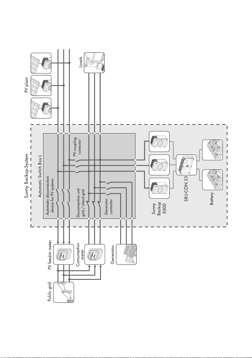
The Automatic Switch Box is a switching unit for Backup systems. The Sunny Backup regulates and
controls the Automatic Switch Box and forms a stand-alone grid in case of a power outage. During a
grid failure, the Automatic Switch Box safely disconnects the connected PV plant and the connected
loads from the power distribution grid and connects them to the stand-alone grid.
In case you ordered the Automatic Switch Box with generator connection, you can include a
generator into your Backup system. If a generator is included into the Backup system, it can be
connected to the stand-alone grid via the Automatic Switch Box in case of a grid failure, if required.
The Automatic Switch Box M-20 and the Automatic Switch Box L-20 are both suited for TT systems
and TN systems.
You may operate the Automatic Switch Box M-20 only in combination with a Sunny Backup 5000
and the Automatic Switch Box L-20 only in combination with 3 Sunny Backup 5000. In a 3-phase
Backup system you must configure one of the 3 Sunny Backup systems as a master and the other 2
as slave. The Sunny Backup master evaluates the data recorded in the Automatic Switch Box,
coordinates all switching operations and controls all components of the Backup system. You will find
further information in the Sunny Backup 5000 manual.
Do not exceed the maximum connection power of the individual outgoing lines in the
Automatic Switch Box. You will find the maximum connection power in section 10”Technical
Data”,page53.
Do not use the Automatic Switch Box for purposes other than those described here. Alternative uses,
modifications, and the installation of components void the warranty claims and operation permit.
This guide is part of the Automatic Switch Box. Pay attention to all the activities described in this guide.
Keep this guide in a convenient place for future reference.
6 AS-BOX-M_L-IA-IEN110320 Installation Guide
Page 7
SMA Solar Technology AG 2Safety
Principle of a 3-phase Backup system including an Automatic Switch Box
Installation Guide AS-BOX-M_L-IA-IEN110320 7
Page 8
2Safety SMA Solar Technology AG
2.2 Safety Instructions
Danger to life due to high voltages.
• All work on the Automatic Switch Box must be performed by electrically skilled persons.
2.3 Explanation of Symbols
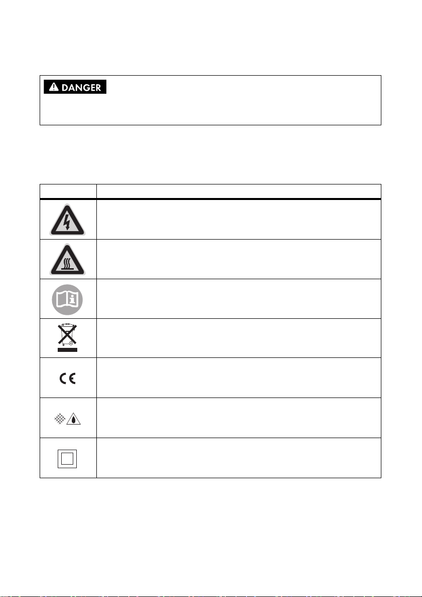
2.3.1 Symbols on the Type Label
Symbol Description
Beware of dangerous electrical voltage.
The Automatic Switch Box operates at high voltages. All work on the
Automatic Switch Box must be performed by electrically skilled persons.
Beware of hot surface.
The Automatic Switch Box can become hot during operation. Avoid contact during
operation.
Observe all documents provided.
Do not dispose of the Automatic Switch Box and its components via the household
garbage (see section 9.3”Disposing of the Automatic Switch Box”,page52).
CE mark.
The Automatic Switch Box complies with the requirements of the applicable EC
guidelines.
Protection rating IP54.
The Automatic Switch Box is protected against dust deposits in the interior and
splashes of water from all angles. Complete contact protection.
Protection class II.
The Automatic Switch Box has a double insulation and is therefore protected
against direct as well as indirect contact.
8 AS-BOX-M_L-IA-IEN110320 Installation Guide
Page 9
SMA Solar Technology AG 2Safety
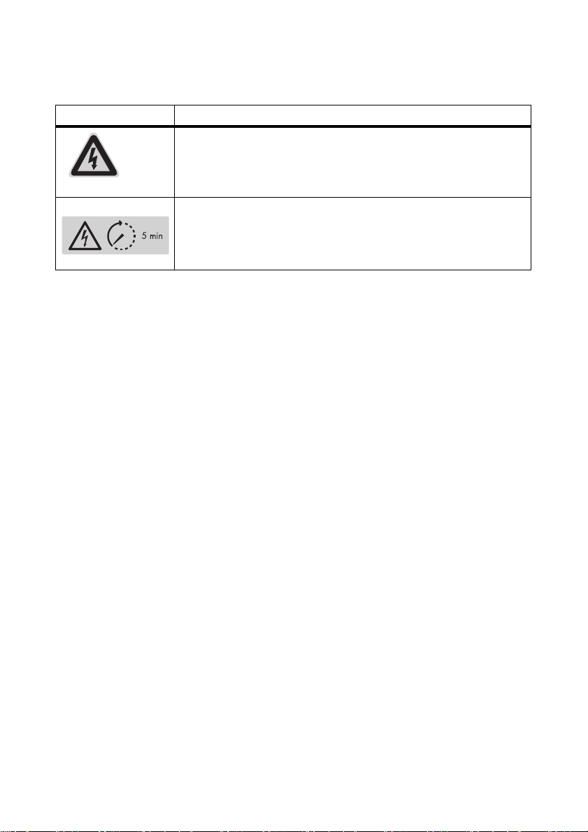
2.3.2 Symbols in the Automatic Switch Box
Symbol Description
Beware of dangerous electrical voltage.
The Automatic Switch Box operates at high voltages. The covers inside the
Automatic Switch Box serve as contact protection. Do not open covers
during operation.
Beware of dangerous electrical voltage.
After you have disconnected the Automatic Switch Box, the capacitors on
the control board will take 5 minutes to discharge. Wait 5 minutes before
opening the cover.
Installation Guide AS-BOX-M_L-IA-IEN110320 9
Page 10
3Scope of delivery SMA Solar Technology AG
3Scope of delivery
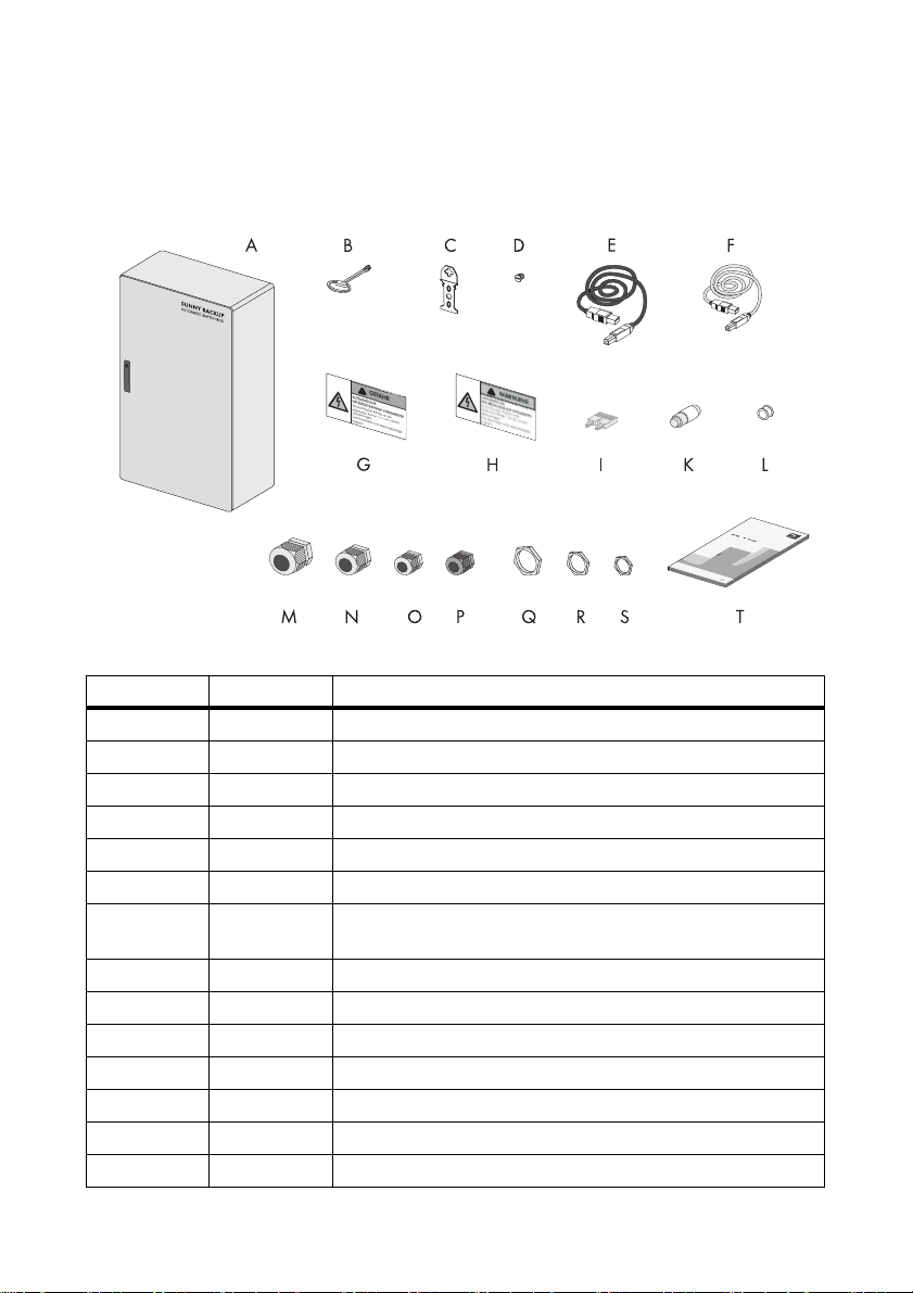
3.1 Automatic Switch Box M
Figure1:Scope of delivery of the Automatic Switch Box M
Position Number Description
A 1 Automatic Switch Box
B 1 Switch cabinet key
C4Exterior attachment
D4Plug
E 1 Communication cable; red
F 1 Communication cable; black
G 3 Warning sticker: "Automatic emergency backup-up power system
present!"; german, english, greek
H 3 Warning sticker: "Phase coupling"; german, english, greek
I 1 Push-in type jumper bar
K 4 Fuse link D02; 40 A
L 4 Headed sleeve for fuse link D02; 40 A
M 3 M32x1.5 cable gland; reduced grip range
N 3 M25x1.5 cable gland
O 3 M20x1.5 cable gland; reduced grip range
10 AS-BOX-M_L-IA-IEN110320 Installation Guide
Page 11

SMA Solar Technology AG 3Scope of delivery
Position Number Description
P 1 M20x1.5 cable gland
Q1 Counter nut M32
R3Counter nut M25
S4Counter nut M20
T 1 Installation Guide
Installation Guide AS-BOX-M_L-IA-IEN110320 11
Page 12
3Scope of delivery SMA Solar Technology AG
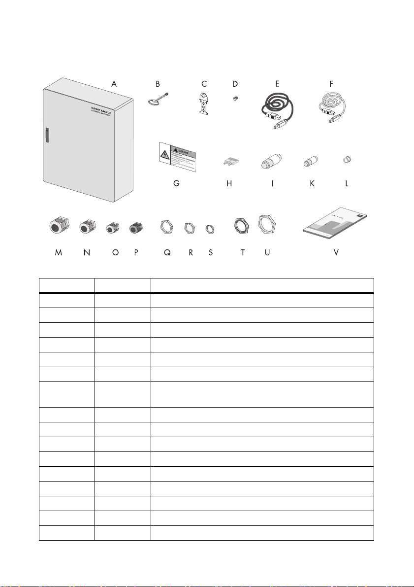
3.2 Automatic Switch Box L
Figure2:Scope of delivery for the Automatic Switch Box L
Position Number Description
A 1 Automatic Switch Box
B 1 Switch cabinet key
C4Exterior attachment
D4Plug
E 3 Communication cable; red
F 1 Communication cable; black
G 3 Warning sticker: "Automatic emergency backup-up power system
present!"; german, english, greek
H 1 Push-in type jumper bar
I 3 Fuse link D02; 63 A
K 3 Fuse link D02; 50 A
L 3 Headed sleeve for fuse link D02; 50 A
M 5 M32x1.5 cable gland
N 3 M25x1.5 cable gland
O 3 M20x1.5 cable gland; reduced grip range
P 1 M20x1.5 cable gland
Q4 Counter nut M32
*
*
12 AS-BOX-M_L-IA-IEN110320 Installation Guide
Page 13

SMA Solar Technology AG 3Scope of delivery
Position Number Description
R3Counter nut M25
S4Counter nut M20
T 1 Reduction M50-M32
U1Counter nut M50
V 1 Installation Guide
*
optional
Installation Guide AS-BOX-M_L-IA-IEN110320 13
Page 14
4Mounting the Automatic Switch Box SMA Solar Technology AG
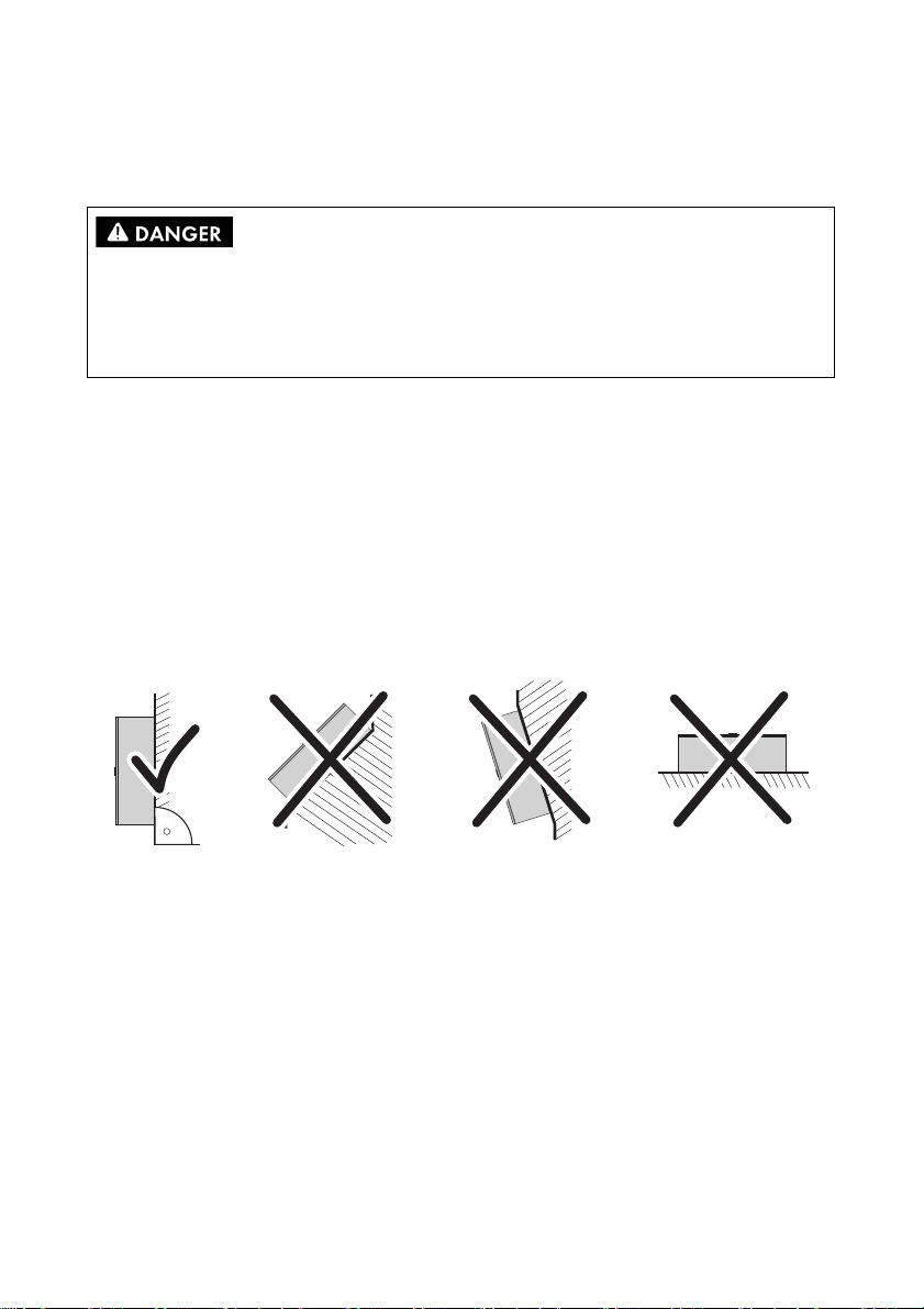
4 Mounting the Automatic Switch Box
Requirements for the mounting location:
Danger to life due to fire or explosion.
• Do not mount the Automatic Switch Box on flammable construction materials.
• Do not mount the Automatic Switch Box near highly flammable construction materials.
• Do not mount the Automatic Switch Box in potentially explosive areas.
☐ Foundation consists of solid material.
☐ The foundation is suitable for the weight and dimensions of the Automatic Switch Box (see
section 10”Technical Data”,page53).
☐ The mounting location is accessible at all times.
☐ Climatic conditions are met (see section 10”Technical Data”,page53).
☐ Mounting location is not exposed to direct sunlight.
☐ Mounting location is protected against splashes of water.
☐ Technical connection requirements of the network operator are met.
Mounting position:
Figure3:Permitted and prohibited mounting positions
14 AS-BOX-M_L-IA-IEN110320 Installation Guide
Page 15
SMA Solar Technology AG 4Mounting the Automatic Switch Box
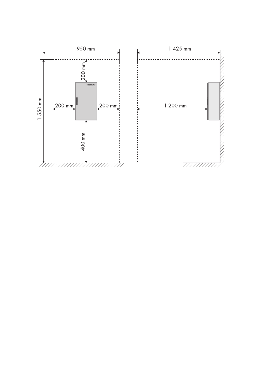
Minimum distances of the Automatic Switch Box M:
Figure4:Distances to be observed for Automatic Switch Box M
Installation Guide AS-BOX-M_L-IA-IEN110320 15
Page 16
4Mounting the Automatic Switch Box SMA Solar Technology AG
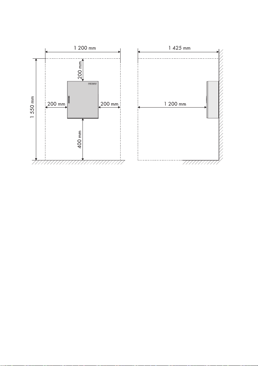
Minimum distances of the Automatic Switch Box L:
Figure5:Distances to be observed for Automatic Switch Box L
16 AS-BOX-M_L-IA-IEN110320 Installation Guide
Page 17
SMA Solar Technology AG 4Mounting the Automatic Switch Box
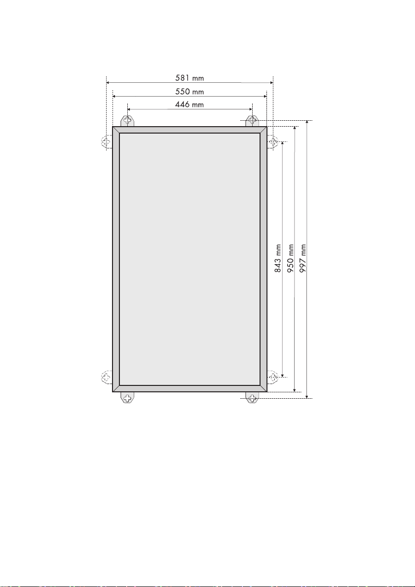
Dimensions of the Automatic Switch Box M:
Figure6:Dimensions of the Automatic Switch Box M with exterior attachments mounted
Installation Guide AS-BOX-M_L-IA-IEN110320 17
Page 18
4Mounting the Automatic Switch Box SMA Solar Technology AG
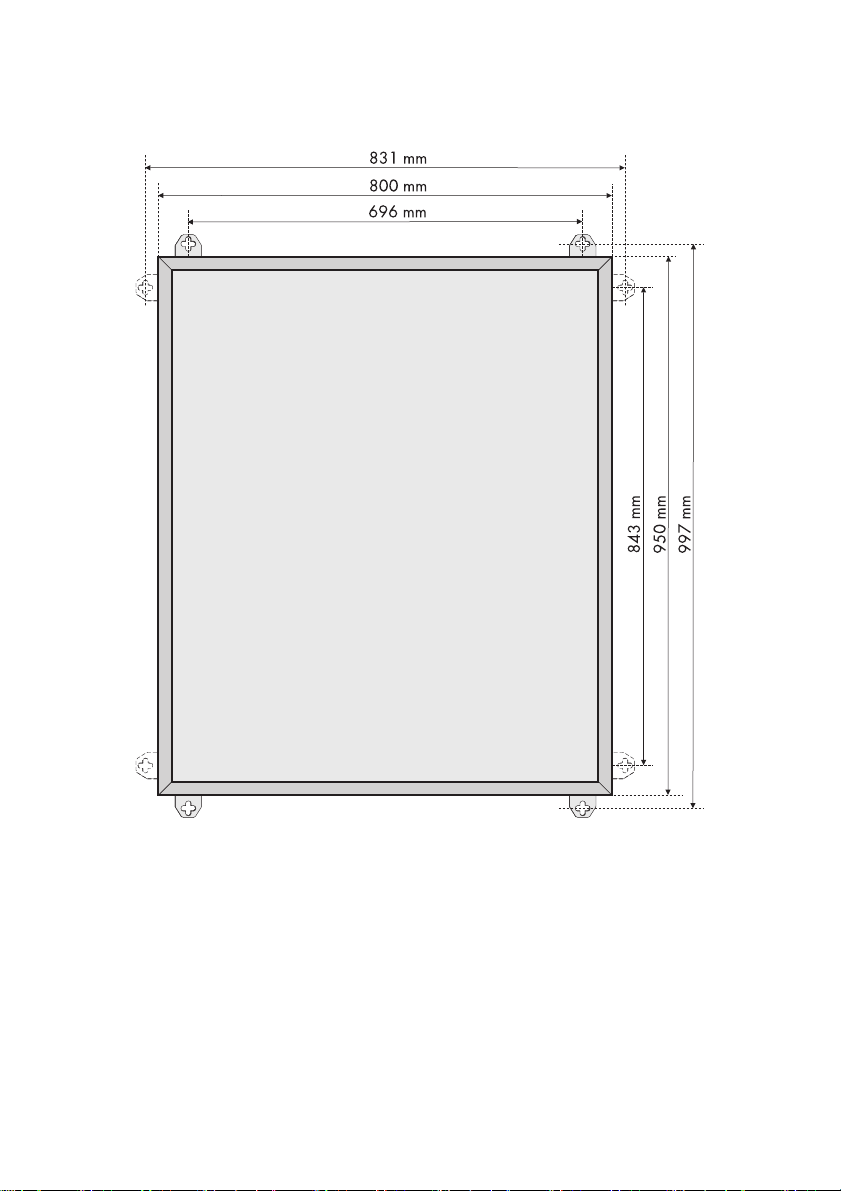
Dimensions of the Automatic Switch Box L:
Figure7:Dimensions of the Automatic Switch Box L with exterior attachments mounted
18 AS-BOX-M_L-IA-IEN110320 Installation Guide
Page 19
SMA Solar Technology AG 4Mounting the Automatic Switch Box
Risk of injury due to the heavy weight of the Automatic Switch Box.
• Take the weight of the Automatic Switch Box into account (see section 10”Technical
Data”,page53).
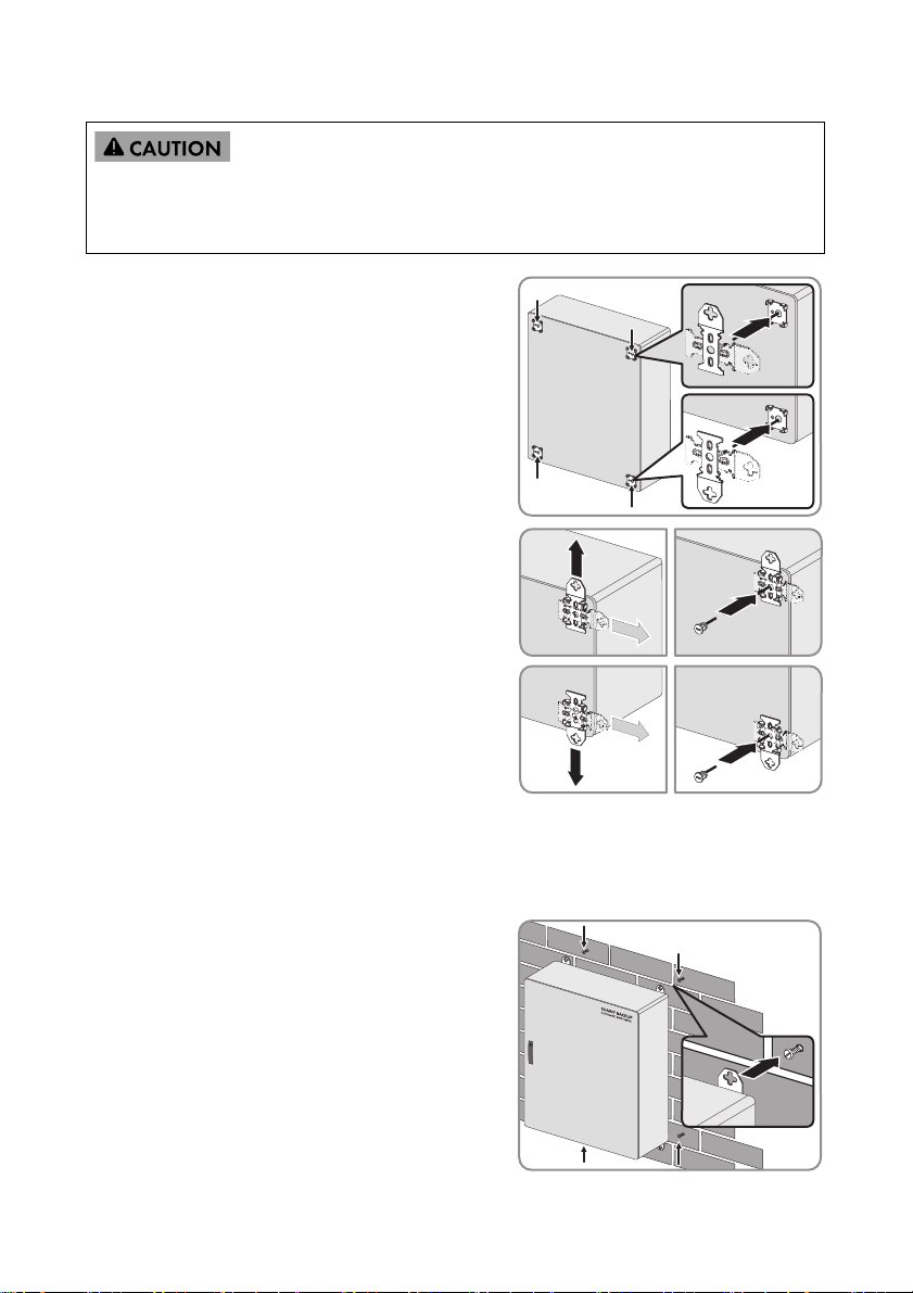
1. Insert the exterior attachments vertically into the
rack on the backside of the Automatic Switch Box.
Hint: The exterior attachments can also be inserted
horizontally into the racks on the backside of the
Automatic Switch Box.
2. Move the upper exterior attachments upwards and
fasten them with plugs. If the exterior attachments
are inserted horizontally, move them sideways.
3. Move the lower exterior attachments downwards
and fasten them with plugs. If the exterior
attachments are inserted horizontally, move them
sideways.
4. Mark the position of the drill holes. Take the dimensions into account.
5. Drill the holes and insert suitable wall anchors.
6. Screw in the M8-screws. Leave the screws protruding out a bit.
7. Hang the Automatic Switch Box, including the
exterior attachments, onto the screws.
Installation Guide AS-BOX-M_L-IA-IEN110320 19
Page 20
5Electrical Connection SMA Solar Technology AG
5 Electrical Connection
5.1 Overview of the Connection Area
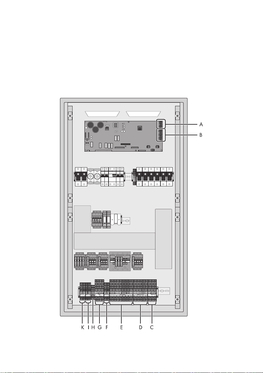
5.1.1 Automatic Switch Box M
Interior View
Figure8:Interior components of the Automatic Switch Box M
20 AS-BOX-M_L-IA-IEN110320 Installation Guide
Page 21

SMA Solar Technology AG 5Electrical Connection
Position Description
A RJ45 socket for connecting the black communication cable
B RJ45 socket for the connection terminal of the red communication cable
C Terminal strip "1_1-X6/ Generator" for connecting the generator
*
D Terminal strip "AS-X3/ Backup Loads" for connecting the loads
E Terminal strip "AS-X1/ Load Meter" for connecting the consumption meter
F Terminal strip "AS-X2/ SBU 5000" for connecting the Sunny Backup
G Terminal strip "AS-X8" for connecting the operational and functional grounding
H Terminal strip "AS-X7 Feed in Signal" for connecting an external signal for battery
feed-in
I Terminal strip "AS-X5/ PV Meter" for connecting the feed-in meter
K Terminal strip "AS-X4/ PV System" for connecting the PV plant or any other
energy source
*
optional
Installation Guide AS-BOX-M_L-IA-IEN110320 21
Page 22

5Electrical Connection SMA Solar Technology AG
Left flange plat
Figure9:Left flange plate including hyphenation points at the bottom of the Automatic Switch Box M
Position Description Explanation
A Hyphenation point for M25x1.5 cable gland For connecting the feed-in meter
B Hyphenation point for M25x1.5 cable gland For connecting the PV plant
C Hyphenation point for M20x1.5 cable gland For connecting the external signal
D Hyphenation point for M20x1.5 cable gland;
reduced
E Hyphenation point for M32x1.5 cable gland For connecting the consumption meter
F Hyphenation point for M20x1.5 cable gland;
reduced
G Hyphenation point for M25x1.5 cable gland For connecting the Sunny Backup
For connecting the functional
grounding
For connecting the operational
grounding
22 AS-BOX-M_L-IA-IEN110320 Installation Guide
Page 23

SMA Solar Technology AG 5Electrical Connection
Right flange plate
Figure10:Right flange plate including hyphenation points at the bottom of the Automatic Switch Box M
Position Description Explanation
A Enclosure opening with filler-plugs for
M32x1.5 cable gland; reduced
B Enclosure opening with filler-plugs for
M32x1.5 cable gland; reduced
C Cable support sleeve For connecting the communication
For connecting the loads
For connecting the generator
cables
Installation Guide AS-BOX-M_L-IA-IEN110320 23
Page 24

5Electrical Connection SMA Solar Technology AG
5.1.2 Automatic Switch Box L
Interior View
Figure11:Interior components of the Automatic Switch Box L
24 AS-BOX-M_L-IA-IEN110320 Installation Guide
Page 25

SMA Solar Technology AG 5Electrical Connection
Position Description
A RJ45 socket for connecting the black communication cable
B RJ45 socket for connecting the red communication cables
C Terminal strip "1_1-X6/ Generator" for connecting the generator
*
D Terminal strip "AS-X1/ Load Meter" for connecting the consumption meter
E Terminal strip "AS-X5/ PV Meter" for connecting the feed-in meter
F Terminal strip "AS-X4/ PV System" for connecting the PV plant or any other
energy source
G Terminal strip "AS-X7 Feed in Signal" for connecting an external signal for
battery feed-in
H Terminal strip "AS-X2/ SBU 5000" for connecting the Sunny Backup
I Terminal strip "AS-X8" for connecting the operational and functional grounding
K Terminal strip "AS-X3/Backup Loads" for connecting the loads
*
optional
Left flange plat
Figure12:Left flange plate including hyphenation points at the bottom of the Automatic Switch Box L
Position Description Explanation
A Hyphenation point for M25x1.5 cable gland For connecting the Sunny Backup
B Hyphenation point for M32x1.5 cable gland For connecting the loads
C Hyphenation point for M20x1.5 cable gland;
reduced
D Hyphenation point for M20x1.5 cable gland;
reduced
For connecting the functional
grounding
For connecting the operational
grounding
E Hyphenation point for M20x1.5 cable gland For connecting the external signal
Installation Guide AS-BOX-M_L-IA-IEN110320 25
Page 26

5Electrical Connection SMA Solar Technology AG
Middle flange plate
Figure13:Middle flange plate including hyphenation points at the bottom of the Automatic Switch Box L
Position Description Explanation
A Hyphenation point for M32x1.5 cable
For connecting the PV plant
gland
B Hyphenation points for M50-M32
For connecting the feed-in meter
reduction and M32x1.5 cable gland
C Hyphenation point for M32x1.5 cable
For connecting the consumption meter
gland
Right flange plate
Figure14:Right flange plate including hyphenation points at the bottom of the Automatic Switch Box L
Position Description Explanation
A Enclosure opening with filler plugs for
For connecting the generator
M32x1.5 cable gland
B Cable support sleeve For connecting the communication
cables
26 AS-BOX-M_L-IA-IEN110320 Installation Guide
Page 27

SMA Solar Technology AG 5Electrical Connection
5.2 Inserting the cable
Insert each cable into the Automatic Switch Box according to the following procedure. Insert the
communication cable as described in section 5.12”Connecting the Communication
Cables”,page44.
Displayed graphics
As an example, only the Automatic Switch Box L will be graphically displayed in this section.
The procedure for the Automatic Switch Box M is identical.
Preparing the Flange Plate
Prepare the left and right flange plate of the Automatic Switch Box M according to the following
procedure.
Prepa re only the le ft and midd le flange plate of the Auto matic S witch Box L acco rding to th e following
procedure. The right flange plate does not need to be prepared.
1. Open the Automatic Switch Box with the switch cabinet key.
2. Loosen the screws of the lower contact protection
and remove the contact protection.
3. Loosen all retaining clips of the flange plates using
a screwdriver.
Installation Guide AS-BOX-M_L-IA-IEN110320 27
Page 28

5Electrical Connection SMA Solar Technology AG
4. Remove the flange plates.
5. Break out the hyphenation points using a
screwdriver and a hammer.
6. Inse rt t he c able gla nds int o th e op eni ngs and fasten
them with counter nuts.
7. Screw the retaining clips of the flange plates with a
screwdriver slightly upwards.
28 AS-BOX-M_L-IA-IEN110320 Installation Guide
Page 29

SMA Solar Technology AG 5Electrical Connection
8. Insert the flange plates into the enclosure of the
Automatic Switch Box and tighten them with
screws.
Routing the cables through cable glands
Route every cable through the cable gland according to the following procedure. Insert the
communication cable as described in section 5.12”Connecting the Communication
Cables”,page44.
1. Slightly loosen the lock nut of the cable gland.
2. Strip cable jacket.
3. Strip off the insulated conductors. Take the stripping length into account
(see section 10”Technical Data”,page53).
4. Insert the cable into the Automatic Switch Box through the cable gland.
5. Tighten the lock nut firmly to the cable gland.
6.
Aluminum cable
If you use an aluminum cable, fill the connection terminals with contact paste.
SMA Solar Technology AG recommends the contact paste "Alu-Plus" from WAGO
company. This prevents contact corrosion.
Installation Guide AS-BOX-M_L-IA-IEN110320 29
Page 30

5Electrical Connection SMA Solar Technology AG
5.3 Connecting functional and operational grounding
Connection terminals "PE" in the Automatic Switch Box
The Automatic Switch Box corresponds to protection class II. The connection terminals "PE" in
the connection area do not serve as a protective grounding of the Automatic Switch Box
enclosure. Via the connection terminals "PE" in the connection area of the Automatic Switch
Box, PE of the individual terminals will only be routed through the Automatic Switch Box and
distributed in the following installation.
TN system:
When connecting in a TN system, only connect a functional grounding. This connection activates the
EMC interference elimination measures in the Automatic Switch Box. The functional grounding is not
identical to the protective grounding of the Automatic Switch Box.
TT system:
When connecting in a TT system, connect an operational and a functional grounding. This connection
activates the EMC interference elimination measures in the Automatic Switch Box. By means of the
operational grounding, the neutral conductor of the Sunny Backup is grounded via a resistor. The
operational and the functional grounding are not identical to the protective grounding of the
Automatic Switch Box.
Requirements:
☐ In case of a functional grounding, the cable cross-section for copper cables is 6 mm².
☐ In case of a redundant connection of the operational grounding, the cable cross-section for
each copper cable is ≥ 6 mm².
☐ In case of an ordinary connection of the operational grounding, the cable cross-section for
copper cables is ≥ 10 mm².
30 AS-BOX-M_L-IA-IEN110320 Installation Guide
Page 31

SMA Solar Technology AG 5Electrical Connection
Connection terminals:
Displayed graphic
As an example, only the Automatic Switch Box L will be graphically displayed in this section.
The labeling of the connection terminals as well as the procedure for connecting the
Automatic Switch Box M is identical.
1. Insert the cable (see section 5.2).
2. Connecting the functional grounding:
– Connect PE of the building's equipotential bonding bar to the connection terminal "FE" of the
terminal strip "AS-X8".
3.
Risk of fatal injury due to failure of the protective measures in the TT system.
If the operational grounding is not connected to the Automatic Switch Box, the residual current
device between loads and Automatic Switch Box and between PV plant and Automatic Switch
Box will not trip in case of a failure.
• If a TT system is present, connect the operational grounding.
– Connect the PE of the building's equipotential bonding bar to the connection terminal
"GND (PE)" of the terminal strip "AS-X8".
Installation Guide AS-BOX-M_L-IA-IEN110320 31
Page 32

5Electrical Connection SMA Solar Technology AG
5.4 Activating the phase coupling for 1-phase Backup System
In case of a grid failure, the Automatic Switch Box M can supply loads which are not connected to
the Backup-Phase L1. In the event of a grid failure, you can choose whether the Automatic Switch Box
connects all 3 phases or just 2 phases. As soon as the power distribution grid returns, the
Automatic Switch Box disconnects the connected phases.
Switch-over times to Backup operation
The switch-over times for the loads on L2 and L3 are longer than for the loads on the Backupphase L1. The switch-over times just take seconds.
Capacity overload of Sunny Backup during phase coupling
• Only activate phase couplings for phases whose power does not exceed the maximum
power of the Sunny Backup (see section 10 "Technical data", Page 52).
Destruction of 3-phase loads during phase coupling.
• During phase coupling only connect 1-phase loads to the Automatic Switch Box.
• Switch on switch-disconnector "Q9" and "Q10" for coupling all 3 phases in the case of a grid
failure.
• Switch on switch-disconnector "Q9" for coupling L1 and L2 in case of a grid failure.
• Switch on switch-disconnector "Q10" for coupling L1 and L3 in case of a grid failure.
• Attach warning sticker "phase coupling" in the distribution when phase coupling is activated.
• Check if the parameter "224.01 SilentEna" of the Sunny Backup is set to Disable when phase
coupling is activated. If the parameter "224.01 SilentEna" is set to Enable, set the parameter on
Disable. This is to deactivate the "Silent Mode" of the Sunny Backup and to make the phase
coupling of the Automatic Switch Box possible.
32 AS-BOX-M_L-IA-IEN110320 Installation Guide
Page 33

SMA Solar Technology AG 5Electrical Connection
5.5 Connecting Loads
Overcurrent protective device and switch-disconnector:
During stand-alone grid operation, the Sunny Backup and the PV plant supply the loads. This disables
the fuse on the grid side. During stand-alone grid operation, the fuse-switch-disconnector "AS-F5"
protects the loads' cables against overload.
Risk of lethal electric shock in the TT system without personal protection.
• Install residual current devices between the Backup system and the loads' electric circuit.
Requirements for the residual current device in the TT system:
☐ The nominal tripping current is 100 mA maximum.
☐Secure tripping with several residual current devices is provided if
g x ΣI
g = coincidence factor of the residual current devices
ΣI
Coincidence factor
g = 1 corresponds to 1 residual current device in the system.
g = 0.5 corresponds to 2 ... 4 residual current devices in the system.
g = 0.35 corresponds to 5 ... 10 residual current devices in the system.
g = 0.25 corresponds to > 10 residual current devices in the system.
≤ 100 mA.
ΔN
= total of nominal tripping currents of the residual current devices
ΔN
Installation Guide AS-BOX-M_L-IA-IEN110320 33
Page 34

5Electrical Connection SMA Solar Technology AG
Connection terminals:
Displayed graphic
As an example, only the Automatic Switch Box L will be graphically displayed in this section.
The labeling of the connection terminals as well as the procedure for connecting the
Automatic Switch Box M is identical.
1. Insert the cable (see section 5.2).
2. Connect PE to terminal strip "AS-X3/ Backup Loads". Take the labeling on the connection
terminals into account.
3. Connect N to terminal strip "AS-X3/ Backup Loads". Take the labeling on the connection
terminals into account.
4. Connect L1, L2 and L3 to terminal strip "AS-X3/ Backup Loads". Take the labeling on the
connection terminals into account.
34 AS-BOX-M_L-IA-IEN110320 Installation Guide
Page 35

SMA Solar Technology AG 5Electrical Connection
5.6 Connecting the PV Plant
Connecting other energy sources:
Instead of the PV plant, you can also connect other energy sources (e.g. small wind turbine systems)
to the Automatic Switch Box. In any case, make sure that an energy meter with the corresponding
tariff is connected to the Automatic Switch Box.
A mixing of energy sources (e.g. the connection of a PV plant and a small wind turbine system) is not
admissible on the part of the network operator since the supply rates of the energy sources differ.
TN systems: Overcurrent protective device
The Automatic Switch Box does not replace the distributor box or fuse box of the PV plant.
• Install a line circuit breaker between the Automatic Switch Box and the PV plant. Be sure to
observe all standards applicable to the installation site.
TT system: residual current device
The Automatic Switch Box does not replace the distributor box or fuse box of the PV plant.
• Install a residual current device and a line circuit breaker between the Automatic Switch Box
and the PV plant. Be sure to observe the requirements for residual current devices.
Requirements for the residual current device in the TT system:
☐ The residual current device is suitable for leakage currents of the PV inverter.
☐ The nominal tripping current is 100 mA maximum.
☐Secure tripping with several residual current devices is provided if
g x ΣI
g = coincidence factor of the residual current devices
ΣI
Coincidence factor
g = 1 corresponds to 1 residual current device in the system.
g = 0.5 corresponds to 2 ... 4 residual current devices in the system.
g = 0.35 corresponds to 5 ... 10 residual current devices in the system.
g = 0.25 corresponds to > 10 residual current devices in the system.
Cable Requirements:
☐ The cable is dimensioned according to the fuse between the feed-in meter and the
Automatic Switch Box and according to the cross-section of the connection terminals.
☐ I n a B ackup sy ste m wi th gener ato r, t he o utp ut f use of th e ge nerator has been taken into account:
if the gene rator f eed-in at the termin al strip "AS -X6/ Generator" has a higher fuse than the cable
of the feed-in meter, the cables of the PV plant are dimensioned for this increased fuse value.
≤ 100 mA.
ΔN
= total of nominal tripping currents of the residual current devices
ΔN
Installation Guide AS-BOX-M_L-IA-IEN110320 35
Page 36

5Electrical Connection SMA Solar Technology AG
Connection terminals:
Displayed graphic
As an example, only the Automatic Switch Box L will be graphically displayed in this section.
The labeling of the connection terminals as well as the procedure for connecting the
Automatic Switch Box M is identical.
1. Insert the cable (see section 5.2).
2. Connect PE to terminal strip "AS-X4/ PV System". Take the labeling on the connection terminals
into account.
3. Connect N to terminal strip "AS-X4/ PV System". Take the labeling on the connection terminals
into account.
4. If yo u us e th e Au tom ati c Sw itc h Bo x M, con nec t L t o te rmi nal strip "L1" of the connection terminal
"AS-X4/ PV System".
5. If you use the Automatic Switch Box L, connect L1, L2 and L3 to the terminal strip
"AS-X4/ PV System". Take the labeling on the connection terminals into account.
36 AS-BOX-M_L-IA-IEN110320 Installation Guide
Page 37

SMA Solar Technology AG 5Electrical Connection
5.7 Connecting the Feed-in Meter
Connection terminals:
Displayed graphic
As an example, only the Automatic Switch Box L will be graphically displayed in this section.
The labeling of the connection terminals as well as the procedure for connecting the
Automatic Switch Box M is identical.
1.
Destruction of the Automatic Switch Box due to missing back-up fuse.
To limit a possible short-circuit current from the power distribution grid and to protect the cables
in the Automatic Switch Box, a fuse between feed-in meter and the Automatic Switch Box is
necessary.
• Install a line fuse between the Automatic Switch Box and the feed-in meter. Take the
no min al c urr ent , th e sh ort -ci rcu it switc hin g ca pac iti es a nd t he maximum cut-off current into
account (see section 10”Technical Data”,page53).
2. If a feed-in meter does not need to be connected to the Automatic Switch Box, bridge the
terminal strips "AS-X5/ PV Meter" and "AS-X1/ Load Meter“.
3. Insert the cable (see section 5.2).
4. Connect PE to terminal strip "AS-X5/ PV Meter". Take the labeling on the connection terminals
into account.
5. Connect N to terminal strip "AS-X5/ PV Meter". Take the labeling on the connection terminals
into account.
6. If yo u us e th e Au tom ati c Sw itch Box M, c onn ect L to ter min al strip "L1" of the con nec tio n te rmi nal
"AS-X5/ PV Meter".
7. If you use the Automatic Switch Box L, connect L1, L2 and L3 to the terminal strip
"AS-X5/ PV Meter". Take the labeling on the connection terminals into account.
Installation Guide AS-BOX-M_L-IA-IEN110320 37
Page 38

5Electrical Connection SMA Solar Technology AG
5.8 Connecting the Consumption Meter
Risk of lethal electric shock.
The residual current devices between the power distribution grid and the Automatic Switch Box
would lose its protective function due to the Backup system. Since the Backup system makes the
tripping of the residual current device ineffective.
• Do not install a residual current device between the power distribution grid and the
Automatic Switch Box.
Risk of electric shock due to connected neutral conductor when connecting in a TN
system.
The Backup system requires a grounded neutral conductor in order to form a TN grid in case of a
grid failure and be able to apply the appropriate protective measures.
• Do not install any switching elements in the grounded neutral conductor to the
Automatic Switch Box.
Risk of electric shock due to incorrect grounding of the PEN conductor on the grid side in
case of a connection to a TN system.
• Ground the PEN conductor on the grid side within the house connection box (e.g. when the
house connection box is linked to the equipotential bonding bar).
Destruction of the Automatic Switch Box due to missing back-up fuse.
To limit a possible short-circuit current from the power distribution grid and to secure the cables in
the Automatic Switch Box, a fuse between the consumption meter and the Automatic Switch Box is
necessary.
• Insert a back-up fuse into the distribution. Take the nominal current, the short-circuit switching
capacities and the maximum cut-off current into account (see section 10”Technical
Data”,page53).
Connection terminals:
Displayed graphic
As an example, only the Automatic Switch Box L will be graphically displayed in this section.
The labeling of the connection terminals as well as the procedure for connecting the
Automatic Switch Box M is identical.
38 AS-BOX-M_L-IA-IEN110320 Installation Guide
Page 39

SMA Solar Technology AG 5Electrical Connection
1. Insert the cable (see section 5.2).
2. Con nec t PE t o te rmi nal str ip " AS-X1/ Load Meter". Take the labeling on the connection terminals
into account.
3. If a TN system is present:
– Bridge the connection terminal "N-TT" and
"N-TN" of the terminal strip "AS-X1/ Load
Meter" b y us ing a pu sh- in t ype jum per bar . Ta ke
the label "TN-TT" in the Automatic Switch Box
into account.
– Connect N to connection terminal "N-TN" of the terminal strip "AS-X1/ Load Meter". Take
the label "TN-TT" in the Automatic Switch Box into account.
4. If a TT system is present:
– If connection terminals "N-TT" and "N-TN" of the terminal strip "AS-X1/ Load Meter" are
bridged, remove the bridge.
– Connect N to connection terminal "N-TT" of the terminal strip "AS-X1/ Load Meter". Take the
label "TN-TT" in the Automatic Switch Box into account. The second connection terminal
"N-TT" is not assigned.
5. Connect L1, L2 and L3 to terminal strip "AS-X1/ Load Meter". Take the labeling on the
connection terminals into account.
Installation Guide AS-BOX-M_L-IA-IEN110320 39
Page 40

5Electrical Connection SMA Solar Technology AG
5.9 Connecting the Sunny Backup
Sunny Backup are fused with a C32 A line circuit breaker inside the Automatic Switch Box.
Only connect one Sunny Backup (master) to the Automatic Switch Box M.
Connect all 3 Sunny Backup (master, slave 1 and slave 2) to the Automatic Switch Box L.
Connection terminals:
Displayed graphic
As an example, only the Automatic Switch Box L will be graphically displayed in this section.
The labeling of the connection terminals as well as the procedure for connecting the Automatic
Switch Box M is identical.
1. Insert all cables (see section 5.2).
2. Connect master to the terminal strip "AS-X2/ SBU5000":
– Connect PE. Take the labeling on the connection terminals into account.
– Connect N. Take the labeling on the connection terminals into account.
–Connect L to the "L1" connection terminal.
3. Connect slave 1 to the terminal strip "AS-X2/ SBU5000":
– Connect PE. Take the labeling on the connection terminals into account.
– Connect N. Take the labeling on the connection terminals into account.
–Connect L to the "L2" connection terminal.
4. Connect slave 2 to the terminal strip "AS-X2/ SBU5000":
– Connect PE. Take the labeling on the connection terminals into account.
– Connect N. Take the labeling on the connection terminals into account.
–Connect L to the "L3" connection terminal.
40 AS-BOX-M_L-IA-IEN110320 Installation Guide
Page 41

SMA Solar Technology AG 5Electrical Connection
5.10 Connecting External Signal for Battery Feed-In
By connecting a potential-free contact to the Automatic Switch Box, you can start or stop grid feed-in
from the battery. You can connect for example a relay output of a ripple control receiver to the
terminal strip "AS-X7/ Feed in Signal" which receives signals from the network operator.
Approval from the network operator
The responsible network operator must approve feed-in from the battery into the power
distribution grid.
Requirements:
☐ The cross-section of the insulated conductor is 2.5 mm² maximum.
☐ The potential-free contact is suited for a grid voltage of 230 V.
Connection terminals:
Displayed graphic
As an example, only the Automatic Switch Box L will be graphically displayed in this section.
The labeling of the connection terminals as well as the procedure for connecting the
Automatic Switch Box M is identical.
1. Insert the cable (see section 5.2).
2. Connect PE to terminal strip "AS-X7/ Feed in Signal". Take the labeling on the connection
terminals into account.
3. Connect the remaining insulated conductors to connection terminals "In" and "L1" of t he t erm ina l
strip "AS-X7/ Feed in Signal".
Installation Guide AS-BOX-M_L-IA-IEN110320 41
Page 42

5Electrical Connection SMA Solar Technology AG
5.11 Connecting the Generator
De pen din g on the pur cha se order , th e Au tom ati c Sw itc h Bo x is equ ipp ed w ith ter min al s trip "1_ 1-X 6/
Generator". You can connect a generator to this terminal strip.
Bridge in terminal strip "1_1-X6/ Generator"
The connection terminals "N" and "PE" of the terminal strip "1_1-X6/ Generator" are bridged.
Output fuse of the generator has an impact on the design of the cable in the PV plant
Note that the design of the outpu t fuse of the generator influences the design of the cable in the
PV plant.
Cable requirements:
☐ The cross-section of the insulated conductor has been selected due to the nominal power of the
generator.
☐ If the generator has no output fuse, the cable is laid in such way that it is protected against
ground faults and short-circuits.
☐ In case of longer cable routes, an additional fuse box is installed in proximity to the generator.
Connection terminals:
Displayed graphic
As an example, only the Automatic Switch Box L will be graphically displayed in this section.
The labeling of the connection terminals as well as the procedure for connecting the
Automatic Switch Box M is identical.
42 AS-BOX-M_L-IA-IEN110320 Installation Guide
Page 43

SMA Solar Technology AG 5Electrical Connection
Risk of lethal electric shock without an operating contact protection.
• Connect the generator directly to the Automatic Switch Box.
or
• Connect the generator to the side of the generator and to the side of the Automatic Switch
Box using a plug with protection against contact.
1. Remove filler-plug from the enclosure opening for M32x1.5 cable gland in the right flange
plate.
2. Attach the M32x1.5 cable gland to the enclosure opening.
3. Route the cable through the cable gland (see section 5.2).
4. Con nec t PE to t erm ina l st rip "1_1-X6/ Generator". Take the labeling on the connection terminals
into account.
5. Connect N to terminal strip "1_1-X6/ Generator". Take the labeling on the connection terminals
into account.
6. If yo u us e th e Au tom ati c Sw itch Box M, c onn ect L to conn ect ion terminal "L1" of the terminal strip
"1_1-X6/ Generator".
7. If you use the Automatic Switch Box L, connect L1, L2 and L3 to the terminal strip
"1_1-X6/ Generator". Take the labeling on the connection terminals into account.
Installation Guide AS-BOX-M_L-IA-IEN110320 43
Page 44

5Electrical Connection SMA Solar Technology AG
5.12 Connecting the Communication Cables
Displayed graphic
As an example, only the Automatic Switch Box L will be graphically displayed in this section.
The procedure for connecting the Automatic Switch Box M is identical.
1. Loosen the screws of the upper right contact
protection and remove the contact protection.
2. Remove the cable support sleeve from the cable
entry.
3. Insert the communication cables through the cable
entry into the Automatic Switch Box.
44 AS-BOX-M_L-IA-IEN110320 Installation Guide
Page 45

SMA Solar Technology AG 5Electrical Connection
4. Insert the communication cables through the cable
channel in the right enclosure wall to the control
board.
5. Place the cable support sleeve around the
communication cables.
6. Press the cable support sleeve into the cable entry.
7. If you use the Automatic Switch Box M, plug the red communication cable into socket
"Mstr/L1 BackupVtgCur".
8. If you use the Automatic Switch Box L, plug a red communication cable into the sockets
"Mstr/L1 BackupVtgCur", "Slv1/L2 BackupVtgCur" and "Slv2/L3 BackupVtgCur".
9. Plug the black communication cable into the socket "ComSyncIn".
10. Mount the upper right and the lower contact protection.
Installation Guide AS-BOX-M_L-IA-IEN110320 45
Page 46

6Commissioning SMA Solar Technology AG
6Commissioning
6.1 Dimensioning the thermal fuse for loads
The dimensioning of the thermal fuse depends on the device type and the size of the fuse in the
distribution.
Selectivity of the thermal fuse:
In unfavorable constellations e.g. the same fuse value is connected twice in a row, it may be
impossible to achieve selectivity between the lead fuses to be inserted and the upstream or
downstream fuses. This is unavoidable due to the complexity of the Backup system with several
feeding sources.
Automatic Switch Box M-20
1. If the rated current of the back-up fuse in the distribution is 40 A, insert a fuse link with a rated
current of 40 A into the fuse-switch-disconnector "AS-F5".
2. If the rated current of the back-up fuse in the distribution is lower than 40 A:
– Insert a fuse link with the same rated current of the back-up fuse in the distribution into the
fuse-switch-disconnector "AS-F5".
– Set the parameter "232.02 GdCurNom" to the value of the back-up fuse via the
Sunny Backup. By doing so, you change the maximum current drawn from the grid.
3. If the rated current of the back-up fuse exceeds 40 A in the distribution:
– Insert a fuse link with a maximum rated current of 40 A into the fuse-switch-disconnector
"AS-F5".
– Insert a fuse with a maximum rated current of 40 A into the distribution.
Automatic Switch Box L-20
1. If the rated current of the back-up fuse is 63 A in the distribution, insert a fuse link with a rated
current of 63 A into the fuse-switch-disconnector "AS-F5".
2. If the rated current of the back-up fuse in the distribution is lower than 63 A:
– Insert a fuse link with the same rated current of the back-up fuse in the distribution into the
fuse-switch-disconnector "AS-F5".
– Set the parameter "232.02 GdCurNom" to the value of the back-up fuse via the
Sunny Backup. By doing so, you change the maximum current drawn from the grid.
3. If the rated current of the back-up fuse exceeds 63 A in the distribution:
– Insert a fuse link with a maximum rated current of 63 A into the fuse-switch-disconnector
"AS-F5".
– Insert a fuse with a maximum rated current of 63 A into the distribution.
46 AS-BOX-M_L-IA-IEN110320 Installation Guide
Page 47

SMA Solar Technology AG 6Commissioning
6.2 Dimensioning the thermal fuse for the generator
Selectivity of the thermal fuse:
In unfavorable constellations e.g. the same fuse value is connected twice in a row, it may be
impossible to achieve selectivity between the lead fuses to be inserted and the upstream or
downstream fuses. This is unavoidable due to the complexity of the Backup system with several
feeding sources.
• Dimension the thermal fuse in accordance with the requirements of the generator.
• If you use the Automatic Switch Box M, insert a fuse link with maximum rated current of 40 A
into the fuse-switch-disconnector "1_1-F6". Use a fuse link of the size D02.
Hint: a fuse link of the size D02 with a rated current of 40 A and appropriate headed sleeves
are included in the scope of delivery.
• If you use the Automatic Switch Box L, insert a fuse link with maximum rated current of 50 A into
the fuse-switch-disconnector "1_1-F6". Use a fuse link of the size D02.
Hint: a fuse link of the size D02 with a rated current of 50 A and appropriate headed sleeves
are included in the scope of delivery.
Installation Guide AS-BOX-M_L-IA-IEN110320 47
Page 48

6Commissioning SMA Solar Technology AG
6.3 Commission the Automatic Switch Box
Requirements:
☐Automatic Switch Box is securely mounted.
☐ All cables are correctly connected.
☐ Contact protections are mounted.
☐ Thermal fuses are correctly dimensioned and inserted into the fuse socket.
Displayed graphic
As an example, only the Automatic Switch Box L will be graphically displayed in this section.
The procedure and labeling of the line circuit breaker and the residual current device is
identical for the Automatic Switch Box M.
1. Switch on the line circuit breaker "AS-F1" and the
residual current device "AS-Q8" in the
Automatic Switch Box.
2. Lock the Automatic Switch Box with the switch
cabinet key.
3. Attach the provided sticker "Automatic emergency
back-up power system present!" in or at the
distribution to which the Backup system is connected. This sticker calls attention to the Backup
system and is intended to ensure that the Backup system is also stopped during work that
requires disconnection.
4. Switch on the line fuse between power distribution grid and Automatic Switch Box.
5. Switch on the line circuit breaker/residual current device between the PV plant and the
Automatic Switch Box.
6.
Destruction of the Automatic Switch Box contactors due to wrong input voltage
range.
If the Backup system is operated outside the specified input voltage range, the Backup system
will turn out.
• If the Automatic Switch Box is equipped with contactors for a higher input voltage range,
set the grid voltage on the Sunny Backup as follows:
– Set the parameter "232.01 GdVtgMin" to 195.5 V. By doing so, you change the
minimum grid voltage.
– Set the parameter "232.02 GdVtgMax" to 260 V. By doing so, you change the
maximum grid voltage.
7. Commission the Backup system (see the manual of the Sunny Backup 5000).
48 AS-BOX-M_L-IA-IEN110320 Installation Guide
Page 49

SMA Solar Technology AG 7Disconnecting the Automatic Switch Box from voltage sources
7 Disconnecting the Automatic Switch Box from voltage
sources
1. Decommission the Backup system (see the manual of the Sunny Backup 5000).
2. Switch off the line fuse between feed-in meter and Automatic Switch Box and between
consumption meter and Automatic Switch Box and secure against re-connection.
3. Switch off the line circuit breaker/residual current device between the PV plant and the
Automatic Switch Box and secure against re-connection.
4. Open the Automatic Switch Box with the switch cabinet key.
5. Switch off the line circuit breaker "AS-F1", the residual current device "AS-Q8" and the fuseswitch-disconnector "F6 (Generator)" in the Automatic Switch Box.
6. Ensure that no voltage is present.
7. Cover or shield any adjacent voltage-carrying parts.
Installation Guide AS-BOX-M_L-IA-IEN110320 49
Page 50

8Maintenance and Cleaning SMA Solar Technology AG
8 Maintenance and Cleaning
The Automatic Switch Box must be maintained and, if necessary, cleaned at regular intervals. SMA
Solar Technology AG recommends to carry out particular maintenance work every 12 months. Note
that the maintenance interval is influenced by the installation site and the ambient conditions.
If the Automatic Switch Box is used in a TN system, the operational grounding resistance needs to be
checked every 5 years.
Maintaining the Automatic Switch Box
• Check interior of the Automatic Switch Box for dirt, moisture and water penetration.
– If necessary, clean the Automatic Switch Box and take appropriate actions.
• Check all connections to ensure that they are securely in place.
– If necessary, re-connect the cables to the connection terminals.
• Check cable insulations, connection terminals and thermal fuses for discoloration.
– If external cabling (e.g. cables leading to loads, PV plant, generator etc.) is discolored,
exchange the cables.
– If interior cabling (e.g. cables leading to contactors or thermal fuses) is discolored, contact
the SMA Serviceline.
Checking the operational grounding resistance
1. Disconnect the Automatic Switch Box from voltage sources (see section 7).
2. Measure the resistance value between the connection terminals "N" of the terminal strips
"AS-X2/ SBU 5000" and "GND (PE)" of the terminal strip "AS-X8" with a test equipment having
an overvoltage category of at least 3.
☑ The resistance is between 225 ohm and 275 ohm.
✖ The resistance is smaller than 225 ohm or larger than 275 ohm?
The N-PE resistance is defective.
• Contact the SMA Serviceline.
50 AS-BOX-M_L-IA-IEN110320 Installation Guide
Page 51

SMA Solar Technology AG 9Decommissioning
9 Decommissioning
9.1 Dismantling the Automatic Switch Box
Displayed graphics
As an example, only the Automatic Switch Box L will be graphically displayed in this section.
The procedure for the Automatic Switch Box M is identical.
Risk of injury due to the heavy weight of the Automatic Switch Box.
• Take the weight of the Automatic Switch Box into account (see section 10”Technical
Data”,page53).
1. Disconnect the Automatic Switch Box from voltage sources (see section 7).
2. Loosen the screws of the upper right contact
protection and remove the contact protection.
3. Loosen the screws of the lower contact protection
and remove the contact protection.
4. Remove all cables from the connection terminals.
5. Remove the upper and lower contact protection.
6. Lock the Automatic Switch Box with the switch cabinet key.
Installation Guide AS-BOX-M_L-IA-IEN110320 51
Page 52

9Decommissioning SMA Solar Technology AG
7. Remove the Automatic Switch Box from the fixing
screws.
9.2 Storing the Automatic Switch Box
Requirements for the storage location:
☐ The storage location is dry.
☐ The ambient temperature is between − 25 °C and +55 °C.
☐ When storing up to a maximum of 24 hours, the ambient temperature is +70 °C maximum.
9.3 Disposing of the Automatic Switch Box
• D isp ose of th e Au tom ati c Swi tch Box i n acc ord anc e wi th t he ap plicable disposal regulations for
electronic waste.
52 AS-BOX-M_L-IA-IEN110320 Installation Guide
Page 53

SMA Solar Technology AG 10Technical Data
10 Technical Data
10.1 Automatic Switch Box M-20
General Data
Number of phases 1-phase
Nominal voltage range 187 V … 253 V
Nominal voltage range in case of higher input voltage
*
range
Nominal frequency range 45 Hz … 55 Hz
Number of Sunny Backup to be connected 1
Permitted grid structure TN-C/TT
Width x height x depth 550 mm x 950 mm x 225 mm
Weight 51 kg
Maximum altitude above MSL 3 000 m
Protection rating of enclosure
Protection rating of inner protective cover
Protection class
***
**
**
EMC environment A/B
EC Declaration of Conformity Yes
Automatic disconnection unit
Inner subdivision
*****
****
Maximum prospective short-circuit current of grid
connection
*
optional
**
according to IEC 60529
***
according to IEC 417
****
according to DIN VDE 0126-1-1
*****
according to IEC 60439-1
195.5 V … 260 V
IP 54
IP 20
II
Yes, in combination with
Sunny Backup 5000
Structure 1 (no subdivision)
25 kA
Installation Guide AS-BOX-M_L-IA-IEN110320 53
Page 54

10Technical Data SMA Solar Technology AG
Rated insulation voltage
Switch cabinet wiring 2.5 kV AC
230 V AC terminals on control board 1.7 kV DC
Communication ports on control board 500 V DC
Load connection
Nominal power at 35 °C 7.4 kW
Nominal current with grid operation per phase at 35 °C 32 A
Power for 30 minutes at 35 °C 8.9 kW
Current with grid operation per phase for 30 minutes at
38 A
35 °C
Maximum cross-section of the insulated conductor to be
16 mm²
connected
Stripping length of the insulated conductors 18 mm … 20 mm
Maximum fuse link to be used D02
Maximum rated current of the fuse link 40 A
Consumption meter connection
Nominal power at 35 °C 7.4 kW
Nominal current at 35 °C 32 A
Power for 30 minutes at 35 °C 8.9 kW
Current with grid operation per phase for 30 minutes at
38 A
35 °C
Maximum cross-section of the insulated conductor to be
16 mm²
connected
Stripping length of the insulated conductors 18 mm … 20 mm
Maximum rated short-circuit current 10 kA
Maximum nominal current of the back-up fuse 40 A
Short-circuit current switch-off capability of the back-up
≥25kA
fuse
Cut-off current of back-up fuse ≤ 17 kA
54 AS-BOX-M_L-IA-IEN110320 Installation Guide
Page 55

SMA Solar Technology AG 10Technical Data
PV plant/feed-in meter connection
Nominal power at 35 °C 5.7 kW
Nominal current at 35 °C 25 A
Power for 30 minutes at 35 °C 6.8 kW
Current for 30 minutes at 35 °C 30 A
Maximum cross-section of the insulated conductor to be
6mm²
connected
Stripping length of the insulated conductors 13 mm … 15 mm
Maximum rated short-circuit current 10 kA
Maximum nominal current of the back-up fuse 32 A
Short-circuit current switch-off capability of the back-up
≥25kA
fuse
Cut-off current of back-up fuse ≤ 17 kA
Sunny Backup connection
Nominal power at 35 °C 5 kW
Nominal current at 35 °C 22 A
Maximum cross-section of the insulated conductor to be
connected
Stripping length of the insulated conductors 13 mm … 15 mm
Fuse C 32 A line circuit breaker
6mm²
Generator connection
Nominal power at 35 °C 7.4 kW
Nominal current at 35 °C 32 A
Power for 30 minutes at 35 °C 8.9 kW
Current for 30 minutes at 35 °C 38 A
Maximum cross-section of the insulated conductor to be
connected
Stripping length of the insulated conductors 18 mm … 20 mm
Maximum fuse link to be used D02
Maximum rated current of the fuse link 40 A
Maximum rated short-circuit current 10 kA
Installation Guide AS-BOX-M_L-IA-IEN110320 55
16 mm²
Page 56

10Technical Data SMA Solar Technology AG
Feed in signal connection
Nominal AC voltage range 195.5 V … 264 V
Maximum cross-section of the insulated conductor to be
2.5 mm²
connected
Stripping length of the insulated conductors 10 mm … 12 mm
Internal consumption
Internal consumption during the day 21 W
Internal consumption at night 16 W
Climatic Conditions
Operating temperature range
*
Air humidity 0 % … 100 %
*
At an ambient temperature of 35 °C, take derating into account.
−25°C … +50°C
56 AS-BOX-M_L-IA-IEN110320 Installation Guide
Page 57

SMA Solar Technology AG 10Technical Data
10.2 Automatic Switch Box L-20
General Data
Number of phases 3-phase
Nominal voltage range 187 V … 253 V
Nominal voltage range in case of higher input voltage
*
range
Nominal frequency range 45 Hz … 55 Hz
Number of Sunny Backup to be connected 3
Permitted grid structure TN-C/TT
Width x height x depth 800 mm x 950 mm x 225 mm
Weight 70 kg
Maximum altitude above MSL 3 000 m
Protection rating of enclosure
Protection rating of inner protective cover
Protection class
***
**
**
EMC environment A/B
EC Declaration of Conformity Yes
Automatic disconnection unit
Inner subdivision
*****
****
Maximum prospective short-circuit current of grid
connection
*
optional
**
according to IEC 60529
***
according to IEC 417
****
according to DIN VDE 0126-1-1
*****
according to IEC 60439-1
195.5 V … 260 V
IP 54
IP 20
II
Yes, in combination with
Sunny Backup 5000
Structure 1 (no subdivision)
25 kA
Rated insulation voltage
Switch cabinet wiring 2.5 kV AC
230 V AC terminals on control board 1.7 kV DC
Communication ports on control board 500 V DC
Installation Guide AS-BOX-M_L-IA-IEN110320 57
Page 58

10Technical Data SMA Solar Technology AG
Load connection
Nominal power at 35 °C 35 kW
Nominal current with grid operation per phase at 35 °C 50 A
Power for 30 minutes at 35 °C 41 kW
Current for 30 minutes at 35 °C 50 A
Maximum cross-section of the insulated conductor to be
16 mm²
connected
Stripping length of the insulated conductors 18 mm … 20 mm
Maximum fuse link to be used D02
Maximum rated current of the fuse link 63 A
Consumption meter connection
Nominal power at 35 °C 35 kW
Nominal current per phase at 35 °C 50 A
Power for 30 minutes at 35 °C 41 kW
Current for 30 minutes at 35 °C 50 A
Maximum cross-section of the insulated conductor to be
connected
Stripping length of the insulated conductors 18 mm … 20 mm
Maximum rated short-circuit current 10 kA
Maximum nominal current of the back-up fuse 63 A
Short-circuit current switch-off capability of the back-up
fuse
Cut-off current of back-up fuse ≤ 17 kA
16 mm²
≥25kA
58 AS-BOX-M_L-IA-IEN110320 Installation Guide
Page 59

SMA Solar Technology AG 10Technical Data
PV plant/feed-in meter connection
Nominal power at 35 °C 28 kW
Nominal current per phase at 35 °C 40 A
Power for 30 minutes at 35 °C 33 kW
Current per phase for 30 minutes at 35 °C 48 A
Maximum cross-section of the insulated conductor to be
16 mm²
connected
Stripping length of the insulated conductors 13 mm … 15 mm
Maximum rated short-circuit current 10 kA
Maximum nominal current of the back-up fuse 50 A
Short-circuit current switch-off capability of the back-up
≥25kA
fuse
Cut-off current of back-up fuse ≤ 17 kA
Sunny Backup connection
Nominal power at 35 °C 15 kW
Nominal current per phase at 35 °C 22 A
Maximum cross-section of the insulated conductor to be
connected
Stripping length of the insulated conductors 13 mm … 15 mm
Fuse C 32 A line circuit breaker
6mm²
Generator connection
Nominal power at 35 °C 27.6 kW
Nominal current per phase at 35 °C 40 A
Power for 5 minutes at 35 °C 33 kW
Current per phase for 5 minutes at 35 °C 40 A
Maximum cross-section of the insulated conductor to be
connected
Stripping length of the insulated conductors 18 mm … 20 mm
Maximum rated short-circuit current 10 kA
Maximum fuse link to be used D02
Maximum rated current of the fuse link 50 A
Installation Guide AS-BOX-M_L-IA-IEN110320 59
16 mm²
Page 60

10Technical Data SMA Solar Technology AG
Feed in signal connection
Nominal AC voltage range 195.5 V … 264 V
Maximum cross-section of the insulated conductor to be
2.5 mm²
connected
Stripping length of the insulated conductors 10 mm … 12 mm
Internal consumption
Internal consumption during the day 114 W
Internal consumption at night 69 W
Climatic Conditions
Operating temperature range
*
Air humidity 0 % … 100 %
*
At an ambient temperature of 35 °C, take derating into account.
−25°C … +50°C
60 AS-BOX-M_L-IA-IEN110320 Installation Guide
Page 61

SMA Solar Technology AG 11Contact
11 Contact
If you have technical problems concerning our products, contact the SM A Serviceline. We re quire the
following information in order to provide you with the necessary assistance:
• Device type (see "Type" on the type label)
• Serial number (see "Serial No." on the type label)
• Article number (see "Art No." on the type label)
• Type and number of the connected Sunny Backup
• Type and number of connected PV inverters
• Type and number of connected loads
• If available: type of connected generators
SMA Solar Technology AG
Sonnenallee 1
34266 Niestetal, Germany
www.SMA.de
SMA Serviceline
Tel. +49 561 9522 399
Fax: +49 561 9522 4697
E-mail: SunnyIsland.Service@SMA.de
Installation Guide AS-BOX-M_L-IA-IEN110320 61
Page 62

Notes SMA Solar Technology AG
62 AS-BOX-M_L-IA-IEN110320 Installation Guide
Page 63

SMA Solar Technology AG Legal Restrictions
The information contained in this document is the property of SMA Solar Technology AG. Publishing its content, either partially or
in full, requires the written permission of SMA Solar Technology AG. Any internal company copying of the document for the
purposes of evaluating the product or its correct implementation is allowed and does not require permission.
Exclusion of liability
The general terms and conditions of delivery of SMA Solar Technology AG shall apply.
The content of these documents is continually checked and amended, where necessary. However, discrepancies cannot be
excluded. No guarantee is made for the completeness of these documents. The latest version is available online at www.SMA.de
or from the usual sales channels.
Guarantee or liability claims for damages of any kind are excluded if they are caused by one or more of the following:
• Damages during transportation
• Improper or inappropriate use of the product
• Operating the product in an unintended environment
• Operating the product whilst ignoring relevant, statutory safety regulations in the deployment location
• Ignoring safety warnings and instructions contained in all documents relevant to the product
• Operating the product under incorrect safety or protection conditions
• Altering the product or supplied software without authority
• The product malfunctions due to operating attached or neighboring devices beyond statutory limit values
• In case of unforeseen calamity or force majeure
The use of supplied software produced by SMA Solar Technology AG is subject to the following conditions:
• SMA Solar Technology AG rejects any liability for direct or indirect damages arising from the use of software developed by
SMA Solar Technology AG. This also applies to the provision or non-provision of support activities.
• Supplied software not developed by SMA Solar Technology AG is subject to the respective licensing and liability agreements
of the manufacturer.
SMA Factory Warranty
The current guarantee conditions come enclosed with your device. These are also available online at www.SMA.de and can be
downloaded or are available on paper from the usual sales channels if required.
Trademarks
All trademarks are recognized even if these are not marked separately. Missing designations do not mean that a product or brand
is not a registered trademark.
The Bluetooth
Solar Technology AG is under license.
SMA Solar Technology AG
Sonnenallee 1
34266 Niestetal
Germany
Tel. +49 561 9522-0
Fax +49 561 9522-100
www.SMA.de
E-Mail: info@SMA.de
© 2004 to 2011 SMA Solar Technology AG. All rights reserved
®
word mar k and lo gos are registered tra demarks ow ned by Bluetoo th SIG, Inc. and any use of such ma rks by SMA
Installation Guide AS-BOX-M_L-IA-IEN110320 63
Page 64

XXX4."4PMBSDPN
4."4PMBS5FDIOPMPHZ
4."4PMBS5FDIOPMPHZ"(
XXX4."EF
4.""NFSJDB--$
XXX4.""NFSJDBDPN
4."5FDIOPMPHZ"VTUSBMJB1UZ-UE
XXX4.""VTUSBMJBDPNBV
4."#FOFMVY413-
XXX4."#FOFMVYDPN
4."#FJKJOH$PNNFSDJBM$P-UE
XXX4."$IJOBDPN
4."$[FDI3FQVCMJDTSP
XXX4."$[FDIDPN
4."'SBODF4"4
XXX4."'SBODFDPN
4.")FMMBT"&
XXX4.")FMMBTDPN
4."*C©SJDB5FDOPMPHB4PMBS4-
XXX4."*CFSJDBDPN
4."*UBMJB4SM
XXX4."*UBMJBDPN
4."5FDIOPMPHZ,PSFB$P-UE
XXX4.",PSFBDPN
 Loading...