

Page 1
Backup-Systeme
AUTOMATIC SWITCH BOX M
Installation Guide
AS-BoxM-IEN091711 | 98-2006411 | Version 1.1
EN
Page 2

Page 3

SMA Solar Technology AG Table of Contents
Table of Contents
1 Notes on this Manual. . . . . . . . . . . . . . . . . . . . . . . . . . . . . . 5
1.1 Validity . . . . . . . . . . . . . . . . . . . . . . . . . . . . . . . . . . . . . . . . . . . . 5
1.2 Target Group . . . . . . . . . . . . . . . . . . . . . . . . . . . . . . . . . . . . . . . 5
1.3 Additional Information . . . . . . . . . . . . . . . . . . . . . . . . . . . . . . . . 5
1.4 Symbols Used . . . . . . . . . . . . . . . . . . . . . . . . . . . . . . . . . . . . . . . 6
2 Security . . . . . . . . . . . . . . . . . . . . . . . . . . . . . . . . . . . . . . . . . 7
2.1 Appropriate Usage. . . . . . . . . . . . . . . . . . . . . . . . . . . . . . . . . . . 7
2.2 Safety Precautions. . . . . . . . . . . . . . . . . . . . . . . . . . . . . . . . . . . . 8
3 Unpacking. . . . . . . . . . . . . . . . . . . . . . . . . . . . . . . . . . . . . . . 9
3.1 Scope of Delivery . . . . . . . . . . . . . . . . . . . . . . . . . . . . . . . . . . . . 9
3.2 Identifying the product . . . . . . . . . . . . . . . . . . . . . . . . . . . . . . . . 9
4 Mounting the Device . . . . . . . . . . . . . . . . . . . . . . . . . . . . . 10
4.1 Selecting the Mounting Location. . . . . . . . . . . . . . . . . . . . . . . . 10
4.2 Mounting the Product on the Wall . . . . . . . . . . . . . . . . . . . . . . 11
5 Electrical Connection . . . . . . . . . . . . . . . . . . . . . . . . . . . . . 13
5.1 Connection Area Overview . . . . . . . . . . . . . . . . . . . . . . . . . . . 14
5.1.1 Interior View . . . . . . . . . . . . . . . . . . . . . . . . . . . . . . . . . . . . . . . . . . . . . . . . . 14
5.1.2 Exterior View . . . . . . . . . . . . . . . . . . . . . . . . . . . . . . . . . . . . . . . . . . . . . . . . . 15
5.2 Connecting Loads . . . . . . . . . . . . . . . . . . . . . . . . . . . . . . . . . . . 16
5.3 Connecting the PV System . . . . . . . . . . . . . . . . . . . . . . . . . . . . 19
5.4 Connecting the Feed-in Meter. . . . . . . . . . . . . . . . . . . . . . . . . . 21
5.5 Connecting the Consumption Meter . . . . . . . . . . . . . . . . . . . . . 24
5.6 Connecting the Sunny Backup . . . . . . . . . . . . . . . . . . . . . . . . . 27
5.7 Connecting External Signal for Battery Feed-In . . . . . . . . . . . . 29
5.8 Connecting a Generator (Optional) . . . . . . . . . . . . . . . . . . . . . 31
Installation Guide AS-BoxM-IEN091711 3
Page 4

Table of Contents SMA Solar Technology AG
5.9 Communication. . . . . . . . . . . . . . . . . . . . . . . . . . . . . . . . . . . . . 33
5.9.1 Connecting Control and Measurement Cable . . . . . . . . . . . . . . . . . . . . . . . 34
5.9.2 Connecting the Communication Cable . . . . . . . . . . . . . . . . . . . . . . . . . . . . . 35
6 Commissioning . . . . . . . . . . . . . . . . . . . . . . . . . . . . . . . . . . 36
7 Opening and Closing. . . . . . . . . . . . . . . . . . . . . . . . . . . . . 37
7.1 Opening the Product. . . . . . . . . . . . . . . . . . . . . . . . . . . . . . . . . 37
7.2 Closing the Product. . . . . . . . . . . . . . . . . . . . . . . . . . . . . . . . . . 37
8 Decommissioning . . . . . . . . . . . . . . . . . . . . . . . . . . . . . . . . 38
8.1 Disassembling the Product . . . . . . . . . . . . . . . . . . . . . . . . . . . . 38
8.2 Storing the Product . . . . . . . . . . . . . . . . . . . . . . . . . . . . . . . . . . 38
8.3 Disposing of the Product . . . . . . . . . . . . . . . . . . . . . . . . . . . . . . 38
9 Technical Data . . . . . . . . . . . . . . . . . . . . . . . . . . . . . . . . . . 39
10 Contact . . . . . . . . . . . . . . . . . . . . . . . . . . . . . . . . . . . . . . . . 41
4 AS-BoxM-IEN091711 Installation Guide
Page 5

SMA Solar Technology AG Notes on this Manual
1 Notes on this Manual
This manual describes the installation and mounting of the Automatic Switch Box. This content was
previously described in the technical description of the Sunny Backup 5000.
Store this manual where it will be accessible at all times.
1.1 Validity
This manual is valid for device type AS-BOX-M.
1.2 Target Group
This manual is for qualified personnel. The tasks described in this manual may only be performed by
qualified personnel.
1.3 Additional Information
Additional information regarding the Sunny Backup system and the automatic Switch Box can be
found in the FAQ section at www.SMA.de.
Installation Guide AS-BoxM-IEN091711 5
Page 6
Notes on this Manual SMA Solar Technology AG
1.4 Symbols Used
The following types of safety precautions and general information are used in this manual:
DANGER!
DANGER indicates a hazardous situation which, if not avoided, will directly result in death
or serious injury.
WARNING!
WARNING indicates a hazardous situation which, if not avoided, could result in death or
serious injury.
CAUTION!
CAUTION indicates a hazardous situation which, if not avoided, could result in minor or
moderate injury.
NOTICE!
NOTICE indicates a situation that can result in property damage if not avoided.
Information
Information provides tips that are valuable for the optimal installation and operation of
your product.
6 AS-BoxM-IEN091711 Installation Guide
Page 7
SMA Solar Technology AG Security
2 Security
2.1 Appropriate Usage
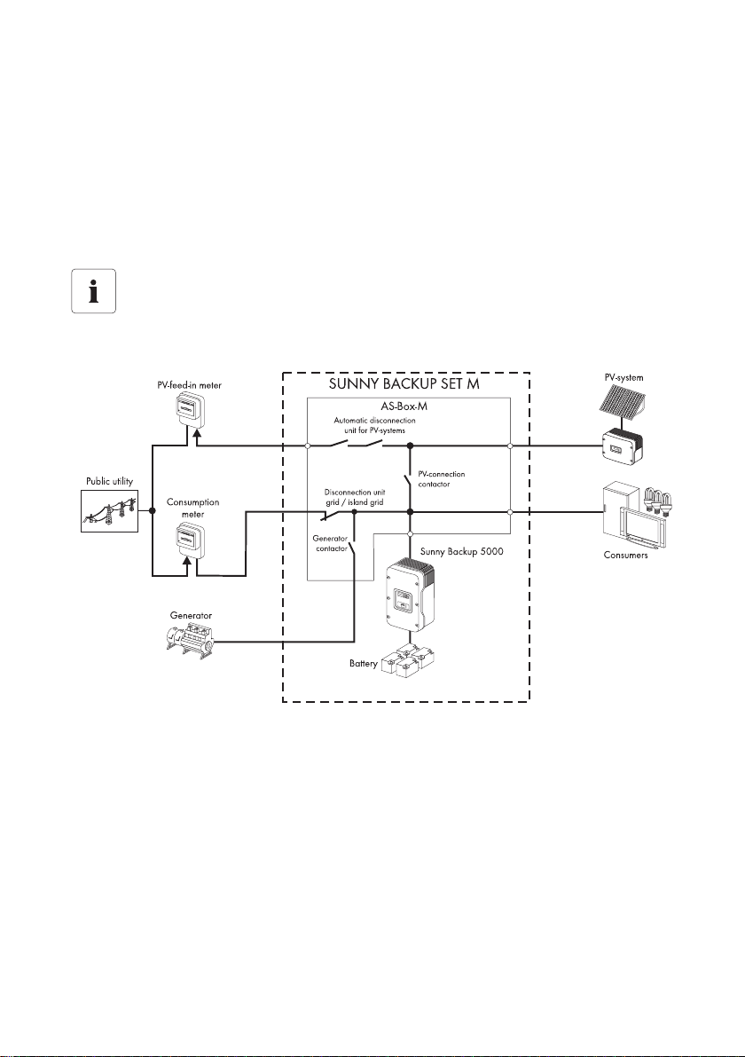
The Automatic Switch Box is a component of a Sunny Backup system M. In case of a grid failure, the
Automatic Switch Box will disconnect the PV system and the loads from the public grid and connect
them to the Sunny Backup. The optional generator is also integrated into the stand-alone grid in the
Automatic Switch Box in case of a grid failure.
Connection requirements
The Sunny Backup system is only certified for TN grids and may not be installed in TT grids.
Principle of an Automatic Switch Box in a Sunny Backup System
The Automatic Switch Box may only be operated in combination with a Sunny Backup. The Sunny
Backup evaluates the data collected by the Automatic Switch Box and coordinates all switching
operations.
The maximum connection power of the individual outgoing lines (e.g. maximum AC PV power to be
connected: 5.7 kW) in the Automatic Switch Box may not be exceeded.
Do not use the Automatic Switch Box for purposes other than those described here. Alternative uses,
modifications, as well as installing components not recommended or sold by SMA may void the
warranty and any applicable interconnection agreements.
Installation Guide AS-BoxM-IEN091711 7
Page 8

Security SMA Solar Technology AG
2.2 Safety Precautions
DANGER!
Danger to life due to high voltages in the Automatic Switch Box.
• All work on the Automatic Switch Box must be performed by a qualified electrician.
8 AS-BoxM-IEN091711 Installation Guide
Page 9
SMA Solar Technology AG Unpacking
3 Unpacking
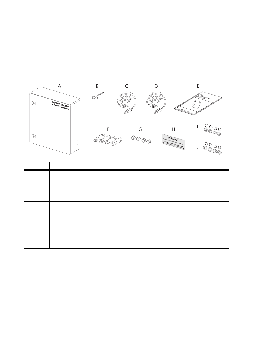
3.1 Scope of Delivery
Check the delivery for completeness and for any visible external damage. Please contact your dealer
in case you find any damage or if there are parts missing.
Object Quantity Description
A1Automatic Switch Box
B 1 Switch cabinet key
C 1 Communication cable (black)
D 1 Control and measurement cable (red)
E 1 Installation guide
F 4 Fuse (35 A)
G 4 Headed sleeve (for 35 A fuse)
H1Label
I 8 4 sealing washers and 4 washers (diameter: 6 mm)
J 8 4 sealing washers and 4 washers (diameter: 8 mm)
3.2 Identifying the product
You can identify the Automatic Switch Box by means of the device type specified on the type label.
The type label is on the right side of the enclosure.
Installation Guide AS-BoxM-IEN091711 9
Page 10
Mounting the Device SMA Solar Technology AG
4 Mounting the Device
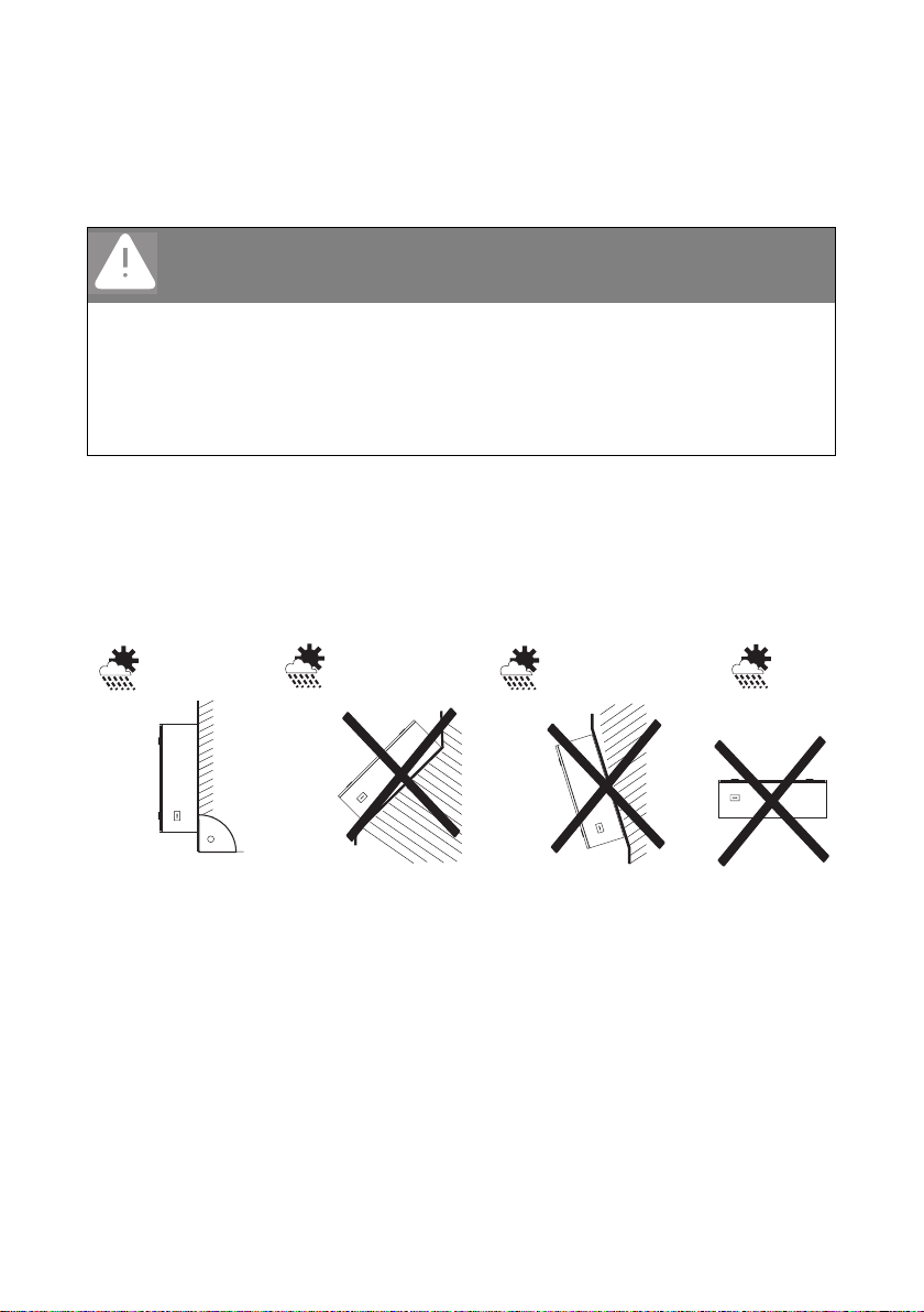
4.1 Selecting the Mounting Location
DANGER!
Danger to life due to fire or explosion.
Despite careful construction, a fire can occur with electrical devices.
The following installation locations are not permitted:
• on flammable construction materials,
• in areas where highly flammable materials are stored
• in potentially explosive areas!
• The mounting location and method must be suitable for the weight and dimensions.
• Installation on a solid surface.
• The installation location must be accessible at all times.
• The ambient temperature must be between –25 °C and +50 °C.
•Mount vertically.
10 AS-BoxM-IEN091711 Installation Guide
Page 11
SMA Solar Technology AG Mounting the Device
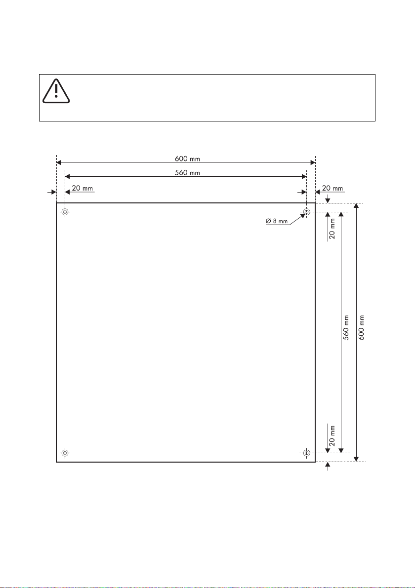
4.2 Mounting the Product on the Wall
CAUTION!
Risk of injury due to the heavy weight of the Automatic Switch Box.
• Take the weight of 29 kg of the Automatic Switch Box into account for mounting.
1. Mark the position of the drill holes.
2. Drill the holes (recommended diameter: 6 mm) at the marked position.
3. Open the Automatic Switch Box with the enclosed switch cabinet key.
Installation Guide AS-BoxM-IEN091711 11
Page 12
Mounting the Device SMA Solar Technology AG
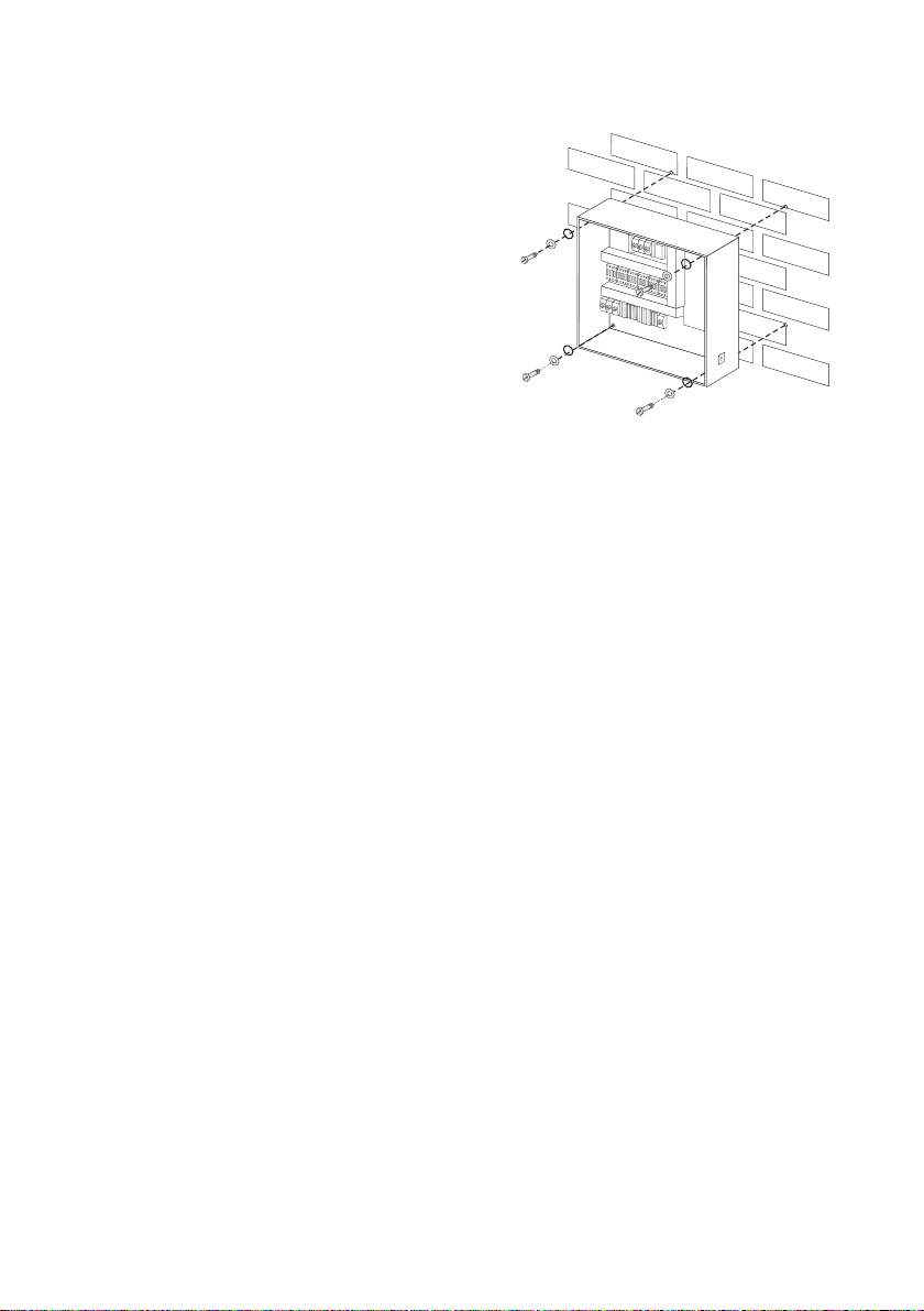
4. Attach the Automatic Switch Box to the wall using
suitable screws and washers.
5. Check that the unit is securely in place.
☑ The Automatic Switch Box is mounted securely on the wall.
12 AS-BoxM-IEN091711 Installation Guide
Page 13
SMA Solar Technology AG Electrical Connection
5 Electrical Connection
NOTICE!
Destruction of the Automatic Switch Box due to excessive cable load.
• Note the bending radii of the cables used.
• Trap cables accordingly (e.g. using a cable anchoring rail).
NOTICE!
Electrostatic discharges can damage the Automatic Switch Box.
Internal components of the Automatic Switch Box can be irreparably damaged by static
discharge.
• Ground yourself before touching a component inside the Automatic Switch Box.
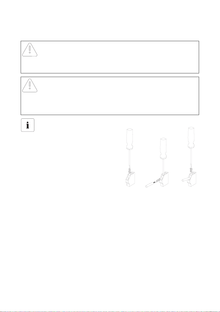
Spring-type terminals
Proceed as shown in the figure in order to
connect a cable to a spring-type terminal
inside the Automatic Switch Box:
Installation Guide AS-BoxM-IEN091711 13
Page 14
Electrical Connection SMA Solar Technology AG
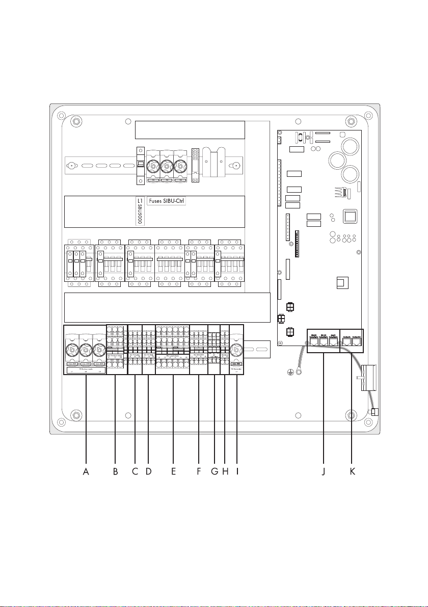
5.1 Connection Area Overview
5.1.1 Interior View
14 AS-BoxM-IEN091711 Installation Guide
Page 15

SMA Solar Technology AG Electrical Connection
Object Description
A Screw type fuse element "F5 Backup Loads" for connecting loads
(L1, L2, L3)
B Connection terminal "X3/Backup Loads" for connecting loads (N, PE)
C Connection terminal "X4/PV System" for connecting the PV system
D Connection terminal "X5/PV Meter" for connecting the feed-in counter
E Connection terminal "X1/Load Meter" for connecting the power supply counter
F Connection terminal "X2/SBU 5000" for connecting the Sunny Backup
G Connection terminals "X7/Feed in Signal" for feed-in from the battery
H Connection terminal "Generator" for connecting the generator (N, PE)
(optional)
I Screw type fuse element "F6 Generator" for connecting the generator (L1) (optional)
J RJ45 socket for control and measurement cable
K RJ45 socket for communication cable
5.1.2 Exterior View
Installation Guide AS-BoxM-IEN091711 15
Page 16

Electrical Connection SMA Solar Technology AG
5.2 Connecting Loads
The cables of the loads are led through fuse elements in the Automatic Switch Box. The fuses are
necessary in order to protect the output cable from overload in stand-alone grid operation. Note that
in stand-alone operation, both the Sunny Backup as well as the PV system can power the loads, and
the upstream fuse on the grid side has no effect in this situation. Determine the required fuse size
according to layout type of the cable and installation conditions, and install appropriate fuse plugs.
The maximum fuse plugs D02 with a nominal current of 35 A which may be used are included in the
scope of delivery.
DANGER!
Risk of death from feedback of the Sunny Backup system into the public grid.
In case of backup, feedback into the public grid can occur through the backup phase and
the 3-phase loads.
Feeding of the P V system and pot entially from the diesel generator only occurs at phase L1
in case of grid failure.
• When connecting 3-phase loads whose coils or resistors are switched in a triangle,
always connect all three phases to the Automatic Switch Box.
Selectivity of thermal fuses
In unfavorable constellations (e.g. the same fuse value twice in a row), it may happen that
it is not possible to select whether to install the thermal fuses as upstream or downstream
fuses. This is unavoidable due to the complexity of the Sunny Backup system with several
feeding sources.
Cable end sleeves
When using fine-wired cables, use cable end sleeves as well.
This only applies to cables connected to the "F5 Backup Loads" fuse element.
Cable Requirements
The cable type and laying method must be suitable for the application and use location.
Cable cross section
16 AS-BoxM-IEN091711 Installation Guide
Page 17

SMA Solar Technology AG Electrical Connection
Sizing the Thermal Fuse
Load disconnection unit
Use only line circuit breakers as load disconnection units!
A screw type fuse element, e.g. D system (Diazed) or D0 system (Neozed) is not a load
disconnection device, and thus may not be used as a load disconnection unit.
Upon disconnection under load, the screw type fuse element of the Automatic Switch Box
may be destroyed, or its functionality may be inhibited by contact burning. It only acts as
cable protection.
In the table, select the condition applying to you and observe the corresponding recommendation by
SMA Solar Technology.
Condition Recommendation
The rating of the back-up fuse in the
distribution is equal to the nominal
current of the Automatic Switch Box
during grid operation (35 A).
The rating of the back-up fuse in the
distribution is lower than the nominal
current of the Automatic Switch Box
during grid operation (35 A).
The rating of the back-up fuse in the
distribution is higher than the nominal
current of the Automatic Switch Box
(35 A).
• Use a fuse with a nominal c urrent of 35 A in th e fuse
element "F5 Backup Loads" in the Automatic Switch
Box.
• Install a fuse with the same nominal current as in the
distribution into the "F5 Backup Loads" fuse element
in the Automatic Switch Box.
• Set the maximum grid current through the Sunny
Backup with the parameter 232.02 GdCurNom to
the value of the rating of the back-up fuse.
• According to the installation, install as fuse not
exceeding 35 A into the fuse element "F5 Backup
Loads" in the Automatic Switch Box.
• Install a fuse with max. 35 A in the distribution.
Installation Guide AS-BoxM-IEN091711 17
Page 18

Electrical Connection SMA Solar Technology AG
Connection Procedure
1. Select the suitable opening for the loads cable and poke a hole in it with a pointy device.
The cable has to be tightly enclosed by the cable gland after insertion.
2. Pull the loads cable through the cable opening into the inside of the Automatic Switch Box.
3. Connect PE and N to the "X3/Backup Loads" connection terminal according to the label. The
second connection terminal "N" is not assigned.
4. Connect L1 and possibly (in case of 3-phase loads) L2 and L3 according to the labels to the
"F5 Backup Loads" fuse elements.
☑ The loads are connected.
18 AS-BoxM-IEN091711 Installation Guide
Page 19

SMA Solar Technology AG Electrical Connection
5.3 Connecting the PV System
Cable Protection
The Automatic Switch Box S is not intended to serve as a distri butor box or fuse box for the
PV system. For safety and disconnection, a line circuit breaker must be installed between
Automatic Switch Box and PV system. Be sure to observe all standards applicable to the
installation and site.
Connection of additional energy sources
Only those energy sources may be connected to the Automatic Switch Box for which the
corresponding tariff of the feed-in counter is valid. Instead of the PV system, you can also
connect other energy sources (e.g. small wind energy systems) to the Automatic Switch
Box. One prerequisite is the fact that a corresponding feed-in meter is connected to the
Automatic Switch Box.
Si nce onl y on e fe ed- in m ete r ma y be con nected to the Aut oma tic Switc h bo x, o nly one tar iff
is specified. The connection of a PV system and a small wind energy system (energy
sources mix) is not possible.
Cable Requirements
The cable type and laying method must be suitable for the application and use location. The cable
after the upstream fuse on the grid side must be selected.
For Sunny Backup systems with a generator connection, attention must also be paid to the fuse
protection of the generator feed-in. If the generator feed-in at the "X6/Generator" connection terminal
has a greater fuse protection than the supply cable from the feed-in meter
(upstream of "X5/PV Meter"), then the output cable from the PV System (X4/PV system) must be
implemented with this higher fuse value.
Cable cross section
Installation Guide AS-BoxM-IEN091711 19
Page 20

Electrical Connection SMA Solar Technology AG
Connection Procedure
1. Select suitable opening for the cable of the PV system and poke a ho le in it with a p ointy d evice.
The cable has to be tightly enclosed by the cable gland after insertion.
2. Pull the cable of the PV system through the opening into the Automatic Switch Box.
3. Connect PE conductor to the "X4/PV system" connection terminal according to the label.
4. Connect L1 and N to the "X4/PV system" connection terminal according to the label.
☑ The PV system is now connected to the Automatic Switch Box.
20 AS-BoxM-IEN091711 Installation Guide
Page 21

SMA Solar Technology AG Electrical Connection
5.4 Connecting the Feed-in Meter
Cable Protection
For safety and disconnection, a line circuit breaker must be installed between Automatic
Sw itc h Bo x an d feed-i n me ter . Be sure to ob ser ve a ll stand ard s applicable to the installation
and site.
Connection requirements
The Sunny Backup system is only certified for TN grids and may not be installed in TT grids.
Comply with all connection regulations of your utility operator.
PV systems without feed-in meter
The Sunny Backup system can also be used in PV systems without feed-in meter. If you do
not connect a feed-in meter to the Automatic Switch Box, you must bridge the feed-in
counter (X5/PV Meter) and the consumption meter (X1/Load Meter) outside of the
Automatic Switch Box.
Installation Guide AS-BoxM-IEN091711 21
Page 22

Electrical Connection SMA Solar Technology AG
Cable Requirements
The cable type and laying method must be suitable for the application and use location.
Cable cross section
The required cross-section of the cables depends on the upstream fuse.
Cable cross section
22 AS-BoxM-IEN091711 Installation Guide
Page 23

SMA Solar Technology AG Electrical Connection
Connection Procedure
1. Select the suitable opening for the feed-in counter cable and poke a hole in it with a pointy
device.
The cable has to be tightly enclosed by the cable gland after insertion.
2. Pull the cable of the feed-in counter through the opening into the Automatic Switch Box.
3. Connect PE to the "X5/PV Meter" connection terminal according to the label.
4. Connect L1 and N to the "X5/PV Meter" connection terminal according to the label.
☑ The feed-in meter is now connected to the Automatic Switch Box.
Installation Guide AS-BoxM-IEN091711 23
Page 24

Electrical Connection SMA Solar Technology AG
5.5 Connecting the Consumption Meter
DANGER!
Risk of lethal electric shock!
Residual current devices (RCD) between grid and Automatic Switch Box would lose their
protective function due to the Backup System.
• Do not connect a residual current device (RCD) between grid and Automatic Switch
Box.
• Do connect a residual current device (RCD) between loads and Automatic Switch
Box.
DANGER!
Risk of death from feedback of the Sunny Backup system into the public grid.
In case of backup, feedback into the public grid can occur through the backup phase and
the 3-phase loads.
Feeding of the P V system and pot entially from the diesel generator only occurs at phase L1
in case of grid failure.
• When connecting 3-phase loads whose coils or resistors are switched in a triangle,
always connect all three phases to the Automatic Switch Box.
DANGER!
Risk of lethal electric shock!
The Sunny Backup system requires a grounded neutral conductor in order to form a TN
grid in case of grid failure and be able to apply the corresponding protective measures.
• Do not install any switching elements in the grounded neutral conductor to the
Automatic Switch Box.
DANGER!
Risk of lethal electric shock!
• Connect the PEN conductor on the grid side within the house connection box to
protective earth.
Example: Connection from house connection box to the equipotential bonding bar.
24 AS-BoxM-IEN091711 Installation Guide
Page 25

SMA Solar Technology AG Electrical Connection
Cable Requirements
The cable type and laying method must be suitable for the application and use location.
Cable cross section
The required cross-section of the cables depends on the upstream fuse.
Cable cross section
NOTICE!
Destruction of the Automatic Switch Box due to overload.
• Use max. one 35 A fuse as back-up fuse in the distribution.
Installation Guide AS-BoxM-IEN091711 25
Page 26

Electrical Connection SMA Solar Technology AG
Connection Procedure
1. Select suitable cable opening for the cable of the power supply counter and poke a hole in it
with a pointy device.
The cable has to be tightly enclosed by the cable gland after insertion.
2. Pull the cable of the power supply counter through the opening into the Automatic Switch Box.
3. Connect PE to the "X1/Load Meter" connection terminal according to the label.
4. Connect L1 and potentially (in case of 3-phase loads) L2 and L3 to the "X1/Load Meter"
connection terminals according to the label.
5. Connect N to the "X1/Load Meter" connection terminals according to the label. The second
connection terminal "N" is not assigned.
☑ The consumption meter is now connected.
26 AS-BoxM-IEN091711 Installation Guide
Page 27

SMA Solar Technology AG Electrical Connection
5.6 Connecting the Sunny Backup
Securing the Sunny Backup
The Sunny Backup is secured with a C32 A line circuit breaker inside the Automatic Switch
Box.
Cable Requirements
The cable type and laying method must be suitable for the application and use location.
Cable cross section
SMA Solar Technology recommends cables with a cross-section of 6 mm
Cable cross section
2
.
Installation Guide AS-BoxM-IEN091711 27
Page 28

Electrical Connection SMA Solar Technology AG
Connection Procedure
1. Select suitable cable opening for the cable of the Sunny Backup and poke a hole in it with a
pointy device.
The cable has to be tightly enclosed by the cable gland after insertion.
2. Pull the cable of the Sunny Backup through the opening into the Automatic Switch Box.
3. Connect PE to the "X2/SBU5000" connection terminal according to the label.
4. Connect L1 and N to the "X2/SBU5000" connection terminal according to the label. The
second connection terminal "N" is not assigned.
☑ The cable for the connection of the Sunny Backup is now connected.
28 AS-BoxM-IEN091711 Installation Guide
Page 29

SMA Solar Technology AG Electrical Connection
5.7 Connecting External Signal for Battery Feed-In
Consent of the utility operators
Battery feed-in into the public grid may only be carried out with the consent of the
responsible utility operators.
The grid feeding from the battery can be started or stopped through the floating contact
"Feed-In Signal". The relay output of a ripple control receiver, for example, can be connected to this
contact which can receive e.g. signals from the utility operator.
Cable Requirements
The cable type and laying method must be suitable for the application and use location.
Cable cross section
Installation Guide AS-BoxM-IEN091711 29
Page 30

Electrical Connection SMA Solar Technology AG
Connection Procedure
1. Select suitable for the cable of the feed-in signal and poke a hole in it with a pointy device.
The cable has to be tightly enclosed by the cable gland after insertion.
2. Pull the cable through the opening into the Automatic Switch Box.
3. Connect PE to the "X7/Feed-In Signal" connection terminal according to the label.
4. Connect the cables to "IN" and "L1".
☑ The external signal for battery feed-in is now connected.
30 AS-BoxM-IEN091711 Installation Guide
Page 31

SMA Solar Technology AG Electrical Connection
5.8 Connecting a Generator (Optional)
Cable Requirements
NOTICE!
Destruction of the cables through faulty cable design.
• Select the required cable cross-section according to the nominal power of the
generator.
• The design of the output fuse of the generator may affect the design of the cable to
the PV system.
• If the generator does not have an output fuse, implement the cable connection to the
Automatic Switch Box in a ground-fault proof and short-circuit proof manner. As an
alternative - especially for long cable distances - you can install an additional fuse
box close to the generator.
• Install fuses and protect the cable to the generator against short-circuit currents from
the grid and against overload.
The cable type and laying method must be suitable for the application and use location.
Cable cross section
Cable end sleeves
When using fine-wired cables, use cable end sleeves as well.
This only applies for the cable connected to the "F6 Generator" fuse element.
Installation Guide AS-BoxM-IEN091711 31
Page 32

Electrical Connection SMA Solar Technology AG
Connection Procedure
1. Selec t suita ble ope ning for the cable of the ge nerator and poke a hole in it with a pointy device.
The cable has to be tightly enclosed by the cable gland after insertion.
2. Pull the cable of the generator through the opening into the Automatic Switch Box.
3. Connect PE to the "Generator" connection terminal according to the label.
4. Connect L to "L1" of the "F6 Generator" fuse element.
Torque: 4 Nm +/– 20 %
5. Connect N to the "Generator" connection terminal according to the label.
☑ The generator is now connected.
32 AS-BoxM-IEN091711 Installation Guide
Page 33

SMA Solar Technology AG Electrical Connection
5.9 Communication
Preparatory Work:
1. Loosen the screws of the fastening plate of the dual cable gland inside the Automatic Switch
Box.
2. Remove fastening plate and place to the side.
3. Remove cable gland from the housing.
4. Loosen screws of the dual cable gland.
5. Detach the half without the T-shaped fastening pieces.
6. Lay the communication cable as well as the control and measurement cable with sufficient
length from the gland to the desired connection through the part of the cable gland with the
T-shaped fastening pieces and fix them with cable ties.
7. Screw both halves back together. Fasten the screws so that they could be loosened by hand.
The cables as well as the placeholder (plastic rod) have to be fitted tightly between both sides
of the dual cable gland. Otherwise, a proper seal of the housing cannot be guaranteed.
8. Insert cable gland including cable into the housing.
9. Attach fastening plate of the dual cable gland and fasten screws by hand.
☑ The cables are led into the Automatic Switch Box.
Installation Guide AS-BoxM-IEN091711 33
Page 34

Electrical Connection SMA Solar Technology AG
5.9.1 Connecting Control and Measurement Cable
The Automatic Switch Box transfers voltage measurement signals and current measurement signals to
the Sunny Backup.
Connection Procedure
Plug the control and measurement cable (red) into the "Mstr/L1 BackupVtgCur" socket on the circuit
board inside the Automatic Switch Box.
☑ The control and measurement cable is now connected.
34 AS-BoxM-IEN091711 Installation Guide
Page 35

SMA Solar Technology AG Electrical Connection
5.9.2 Connecting the Communication Cable
The Automatic Switch Box is controlled by the Sunny Backup via a CAN bus.
Connection Procedure
Plug the communication cable (black) into the "ComSyncIn" socket on the circuit board inside the
Automatic Switch Box. Leave the termination resistor plugged in the "ComSyncOut" socket.
☑ The communication cable is now connected.
Installation Guide AS-BoxM-IEN091711 35
Page 36

Commissioning SMA Solar Technology AG
6 Commissioning
Requirements
Check the following requirements before commissioning:
• Automatic Switch Box is mounted securely to the wall
• All cables are correctly and completely connected
• All cables are tightly enclosed by the cable glands
Commissioning procedure
1. Loosen screw caps of all fuse elements.
2. Insert headed sleeves into all fuse elements.
3. Insert fuses into the screw caps.
4. Install screw caps including fuse into the fuse elements.
5. Lock Automatic Switch Box with the switch cabinet key.
6. Attach enclosed label visibly in the consumer system.
☑ The Automatic Switch Box is now ready for operation.
36 AS-BoxM-IEN091711 Installation Guide
Page 37

SMA Solar Technology AG Opening and Closing
7 Opening and Closing
7.1 Opening the Product
DANGER!
Danger to life due to high voltages in the Automatic Switch Box.
• Switch off the line circuit breaker and secure it to prevent it from being reactivated.
• Ensure that no voltage is present in the system.
NOTICE!
Electrostatic discharges can damage the Automatic Switch Box.
Internal components of the Automatic Switch Box can be irreparably damaged by static
discharge.
• Ground yourself before touching a component inside the Automatic Switch Box.
Open the housing lid with the switch cabinet key.
7.2 Closing the Product
1. Close the housing lid with the switch cabinet key.
2. Switch on the line circuit breaker.
☑ The Automatic Switch Box is now closed.
Installation Guide AS-BoxM-IEN091711 37
Page 38

Decommissioning SMA Solar Technology AG
8 Decommissioning
8.1 Disassembling the Product
CAUTION!
Risk of injury due to the heavy weight of the Automatic Switch Box.
• Take the Automatic Switch Box's weight of 29 kg into account.
1. Open the Automatic Switch Box, as described in Section 7.1 "Opening the Product"
(page37).
2. Remove all cables from the Automatic Switch Box.
3. Lock the Automatic Switch Box with the switch cabinet key.
4. Dismount the Automatic Switch Box.
☑ The Automatic Switch Box is disassembled.
8.2 Storing the Product
Store the Automatic Switch Box in a dry place where the ambient temperature is always between
–25 °C and +50 °C.
8.3 Disposing of the Product
Dispose of the Automatic Switch Box at the end of its service life in accordance with the disposal
regulations for electronic waste which apply at the installation site at that time.
38 AS-BoxM-IEN091711 Installation Guide
Page 39

SMA Solar Technology AG Technical Data
9 Technical Data
General AS-BOX M
Number of phases 1-phase
Nominal voltage 202 ... 253 V
Nominal frequency 45 ... 55 Hz
Number of Sunny Backups 1 x Sunny Backup 5000
Mounting type suspended
Permitted grid structure TN-C / TN-S
Load Connection
Nominal output power / current during grid
operation
Maximum cable cross section
(suitable for connection)
Fuse (maximum to be used) D02 (35 A)
Clamping position Fuse / spring-type terminals
Consumption meter connection
Nominal output power / current 8 kW / 35 A
Maximum cable cross section
(suitable for connection)
Clamping position Spring-type terminals
8 kW / 35 A
2
16 mm
2
16 mm
PV system / feed-in meter connection
Nominal output power / current 5.7 kW / 25 A
Maximum cable cross section
6 mm
2
(suitable for connection)
Clamping position Spring-type terminals
Sunny Backup connection
Nominal output power / current 5 kW / 22 A
Maximum cable cross section
6 mm
2
(suitable for connection)
Fuse C 32 A
Clamping position Fuse / spring-type terminals
Generator connection (optional)
Nominal output power / current 8 kW / 35 A
Maximum cable cross section
16 mm
2
(suitable for connection)
Installation Guide AS-BoxM-IEN091711 39
Page 40

Technical Data SMA Solar Technology AG
Generator connection (optional)
Fuse (maximum to be used) D02 (35 A)
Clamping position Fuse / spring-type terminals
Power consumption
Internal consumption during the day 21 W
Internal consumption at night 16 W
Certificates
Independent disconnection device per
DIN VDE 0126-1-1
Yes, in combination with the Sunny Backup
5000
EC Declaration of Conformity enclosed, download area www.SMA.de
Mechanical Data
Dimensions (W x H x D in mm) 600 x 600 x 210
Weight 29 kg
Ambient Conditions
Ambient temperature –25 °C ... +50 °C
Air humidity 0 ... 100 %
Protection Rating
Protection rating according to DIN EN 60529 IP 65
40 AS-BoxM-IEN091711 Installation Guide
Page 41

SMA Solar Technology AG Contact
10 Contact
If you have technical problems concerning our products, contact our Service Line. We require the
following information in order to provide you with the necessary assistance:
• Type of Automatic Switch Box
• Series number of the Automatic Switch Box
• Type and number of the connected Sunny Backup(s)
SMA Solar Technology AG
Sonnenallee 1
34266 Niestetal, Germany
www.SMA.de
Service Line
Inverters: +49 561 9522 1499
Communication: +49 561 9522 2499
Fax: +49 561 9522 4699
E-Mail: serviceline@SMA.de
Installation Guide AS-BoxM-IEN091711 41
Page 42

Contact SMA Solar Technology AG
42 AS-BoxM-IEN091711 Installation Guide
Page 43

SMA Solar Technology AG Legal Restrictions
The information contained in this document is the property of SMA Solar Technology AG. Publishing its content, either partially or
in full, requires the written permission of SMA Solar Technology AG. Any internal company copying of the document for the
purposes of evaluating the product or its correct implementation is allowed and does not require permission.
Exclusion of liability
The general terms and conditions of delivery of SMA Solar Technology AG shall apply.
The content of these documents is continually checked and amended, where necessary. However, discrepancies cannot be
excluded. No guarantee is made for the completeness of these documents. The latest version is available online at www.SMA.de
or from the usual sales channels.
Guarantee or liability claims for damages of any kind are excluded if they are caused by one or more of the following:
• Damages during transportation
• Improper or inappropriate use of the product
• Operating the product in an unintended environment
• Operating the product whilst ignoring relevant, statutory safety regulations in the deployment location
• Ignoring safety warnings and instructions contained in all documents relevant to the product
• Operating the product under incorrect safety or protection conditions
• Altering the product or supplied software without authority
• The product malfunctions due to operating attached or neighboring devices beyond statutory limit values
• In case of unforeseen calamity or force majeure
The use of supplied software produced by SMA Solar Technology AG is subject to the following conditions:
• SMA Solar Technology AG rejects any liability for direct or indirect damages arising from the use of software developed by
SMA Solar Technology AG. This also applies to the provision or non-provision of support activities.
• Supplied software not developed by SMA Solar Technology AG is subject to the respective licensing and liability agreements
of the manufacturer.
SMA Factory Warranty
The current guarantee conditions come enclosed with your device. These are also available online at www.SMA.de and can be
downloaded or are available on paper from the usual sales channels if required.
Trademarks
All trademarks are recognized even if these are not marked separately. Missing designations do not mean that a product or brand
is not a registered trademark.
The Bluetooth
Solar Technology is under license.
SMA Solar Technology AG
Sonnenallee 1
34266 Niestetal
Germany
Tel. +49 561 9522-0
Fax +49 561 9522-100
www.SMA.de
E-Mail: info@SMA.de
© 2004 to 2009 SMA Solar Technology AG. All rights reserved
®
wor d mark an d logos are registere d trademarks owned by Bl uetoot h SIG, Inc. and an y use of s uch marks by S MA
Installation Guide AS-BoxM-IEN091711 43
Page 44

SMA Solar Technology AG
www.SMA.de
Sonnenallee 1
34266 Niestetal, Germany
Tel.: +49 561 9522 4000
Fax: +49 561 9522 4040
E-Mail: Vertrieb@SMA.de
Freecall: 0800 SUNNYBOY
Freecall: 0800 78669269
 Loading...