

Sloan MCR 4001 Installation Manual
Code No. 0816643 — Rev. 2 (07/14)
MicroPlumb® MCR 4001/4003
SERIES CONTROLLER
INSTALLATION INSTRUCTIONS
Installation of the PWT MICROPlumb MCR 4001/4003
Series Controller incorporates the latest advances in
microprocessor technology to provide maximum control
of your plumbing system. MICROPlumb patented sensing
and metering products can be programmed to do just
about anything you require, when you require it, including
the ability to Delay and Lock-Out fixture activation.
MICROPlumb products control showers, water closets,
lavatory and combination fixtures and help maintain
operation of ON/OFF/DELAY. These modular, flexible
systems for new retrofit or expansion applications, have few
moving parts, no mechanical metering devices, and operate
on low voltage to ensure safety and reliability. The following
instructions will serve as a guide when installing the MCR
4001/4003 Series Controller. As always, good safety
practices and care are recommended when installing your
new controller. If further assitance is required contact your
nearest Sloan PWT Representative office.
Unless otherwise noted, Sloan Valve Company warrants this product, manufactured and sold for commercial or
industrial uses, to be free from defects in material and workmanship for a period of three (3) years (one (1) year for
special finishes, SF faucets, PWT electronics and 30 days for PWT software) from date of first purchase. During this
period, Sloan Valve Company will, at its option, repair, replace, or refund the purchase price of any product which
fails to conform with this warranty under normal use and service. This shall be the sole and exclusive remedy under
this warranty. Products must be returned to Sloan Valve Company, at customer’s cost. No claims will be allowed for
labor, transportation or other costs. This warranty extends only to persons or organizations who purchase Sloan Valve
Company’s products directly from Sloan Valve Company for purpose of resale. This warranty does not cover the life of
the batteries.
THERE ARE NO WARRANTIES WHICH EXTEND BEYOND THE DESCRIPTION ON THE
FACE HEREOF. IN NO EVENT IS SLOAN VALVE COMPANY RESPONSIBLE FOR ANY
CONSEQUENTIAL DAMAGES OF ANY MEASURE WHATSOEVER.
PRIOR TO INSTALLATION
LIMITED WARRANTY
Before you install the MCR series flushometer, be
sure the items listed below are installed.
• 24 VAC step down transformer
• Push buttons
• Flushometer
• Lavatory/Shower solenoids
IMPORTANT:
• ALL PLUMBING SHOULD BE
INSTALLED IN ACCORDANCE
WITH APPLICABLE CODES AND
REGULATIONS.
• WATER SUPPLY LINES MUST BE
SIZED TO PROVIDE AN
ADEQUATE VOLUME OF WATER
FOR EACH FIXTURE.
• FLUSH ALL WATER LINES PRIOR
TO MAKING CONNECTIONS.
• ALL ELECTRICAL WIRING IS TO
BE INSTALLED IN ACCORDANCE
WITH NATIONAL/LOCAL CODES
AND REGULATIONS.

1 - MOUNTING CONTROLLER
A. Remove plastic cover from front of controller.
B. Install controller so that all cables for
solenoids enter from the bottom and all
cables from pushbuttons enter at top.
Controller must be located within 15 It from
7-3/4”
(197 mm)
6-7/8”
(175 mm)
furthest pushbutton and within 200 It of
power supply transformer.
C. Mount controller to wall using mounting
screws and plastic anchors.
NOTE: Extension cables are available as an
option from PWT to allow for installing the
controller up to 35 It from furthest push button.
2 - POWER SUPPLY CONNECTION
A. Make sure power is off to 24 VAC
transformer.
B. Run 18-gauge wire from secondary
side (24 VAC output) of transformer
to terminal block inside controller.
C. Turn power on and look for power
indicator to illuminate.
D. Turn power off until pushbuttons and
solenoids are installed.
IMPORTANT: BE SURE THAT WIRE IS COMPLETELY INSERTED INTO
TERMINAL AND THAT NO STRANDS ARE CROSSING FROM ONE SIDE TO
THE OTHER.
Power
3 - PUSH BUTTONS AND SOLENOID CONNECTIONS
A. Plug RJ-ll connectors from push buttons into
appropriate input connections in controller.
Refer to program type section of these
instructions.
B. Plug RJ-ll connectors from flushometers,
lavatories and/or shower solenoids into
appropriate output connections in controller.
Refer to program type section of these
instructions.
C. Power up controller.
IMPORTANT: MAKE SURE THAT ALL PUSH BUTTONS ARE CONNECTED
TO THE INPUT AND SOLENOIDS CONNECTED TO THE OUTPUT.
IMPROPER CONNECTIONS WILL RESULT IN FAILURE OF CONTROLLER
AND/OR PUSH BUTTONS AND SOLENOIDS AND WILL REQUIRE
REPLACEMENT.
2
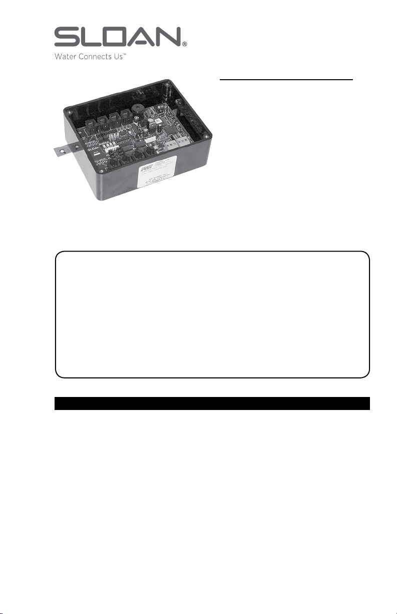
MCR-4001
Controller Shown
 Loading...