

Page 1

Code No. 0816545
Rev. 1 (03/07)
INSTALLATION INSTRUCTIONS FOR DOUBLE AND TRIPLE STATION
SENSOR ACTIVATED SOLID SURFACE LAVATORY SYSTEMS
LIMITED WARRANTY
Sloan Valve Company warrants its Optima EW-70000 Series Lavatory Systems to be made of first class materials, free from defects of material or workmanship under normal use and to perform the service for which they are intended in a thoroughly reliable and efficient manner when properly installed and serviced, for a period of three years (1 year for special finishes) from date of purchase. During this period, Sloan Valve Company will, at its option, repair or replace
any part or parts which prove to be thus defective if returned to Sloan Valve Company, at customer’s cost, and this shall be the sole remedy available under
this warranty. No claims will be allowed for labor, transportation or other incidental costs. This warranty extends only to persons or organizations who purchase Sloan Valve Company’s products directly from Sloan Valve Company for purpose of resale.
THERE ARE NO WARRANTIES WHICH EXTEND BEYOND THE DESCRIPTION ON THE FACE HEREOF. IN NO EVENT IS SLOAN VALVE COMPANY
RESPONSIBLE FOR ANY CONSEQUENTIAL DAMAGES OF ANY MEASURE WHATSOEVER.
EW-72000
Double Station
Sensor Activated
Solid Surface Lavatory System
EW-73000
Triple Station
Sensor Activated
Solid Surface Lavatory System
EW-72000-xx-SD Model Shown
EW-73000-xx-SD Model Shown
Page 2
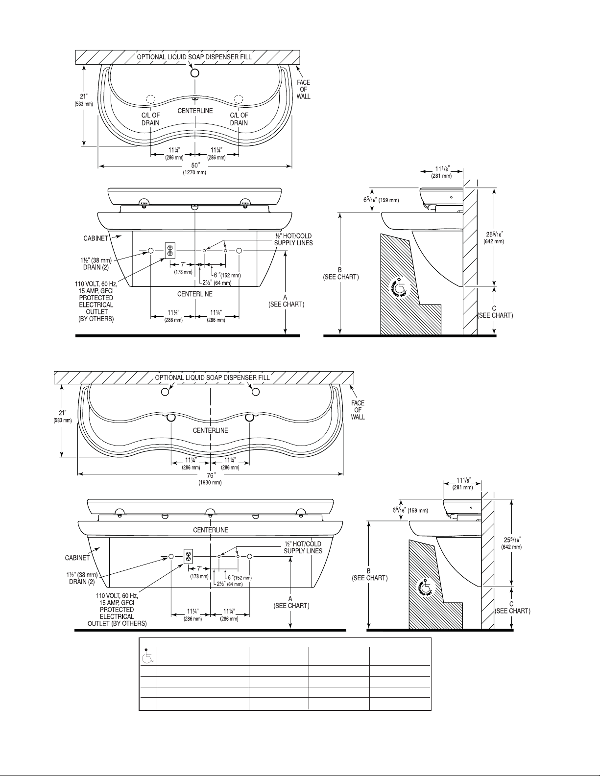
LAVATORY SYSTEM ROUGH-IN
MODEL EW-72000
Double Station Lavatory System
Flow Rate: 0.5 gpm/1.9 Lpm Max. Spray
Lavatory System Weight (Packaged):
Approximately 145 Lbs/65 Kg
2
MODEL EW-73000
Triple Station Lavatory System
Flow Rate: 0.5 gpm/1.9 Lpm Max. Spray
Lavatory System Weight (Packaged):
Approximately 170 Lbs/80 Kg
VARIABLE MOUNTING HEIGHT CHART
DIMENSION T.A.S. † T.A.S. † A.D.A.
DESCRIPTION AGES 4-10 AGES 11-15 STANDARD
A ROUGH-IN 20-1/2” (521 mm) 22-1/2” (572 mm) 24” (610 mm)
B RECOMMENDED RIM HEIGHT 29-7/8” (759 mm) 31-7/8” (810 mm) 33 (838 mm)
C FLOOR CLEARANCE 10-7/8” (276 mm) 12-7/8” (327 mm) 14” (356 mm)
D NOMINAL FRAME HEIGHT ‡ 25-1/8” (638 mm) 27-1/8 (689 mm) 28-1/4” (718 mm)
† When no mirror is required above the basin.
For T.A.S. compliant installations requiring a mirror above the basin, use ELS-72000
products.
‡ Refer to Step 3.
Page 3
PRIOR TO INSTALLATION
Prior to installing the Sloan Optima EW-70000 Series Lavatory System,
install the items listed below. Also, refer to the appropriate rough-in
diagram on Page 2.
• Install electrical receptacle(s) for plug-in transformer(s) — 120 VAC,
2 amp service for each ETF-233 (24 VAC, 35 VA) plug-in transformer
used.
• Hot and cold water supply lines or tempered water supply line (If there
is no tempered water supply, install thermostatic mixing valve
between hot and cold water supply)
• Drain lines
Important:
• ADEQUATE STRUCTURAL SUPPORT IN OR BEHIND THE WALL IS
REQUIRED. REFER TO THE APPROPRIATE ROUGH-IN DIAGRAM ON
PAGE 2 FOR DRY WEIGHT OF SINK. STRUCTURAL SUPPORT
MUST HAVE A MINIMUM PULLOUT RATING OF 1000 POUNDS
(450 Kg) FOR EACH FASTENER.
• ALL ELECTRICAL WIRING SHOULD BE INSTALLED IN ACCORDANCE
WITH NATIONAL/LOCAL CODES AND REGULATIONS.
• ALL PLUMBING SHOULD BE INSTALLED IN ACCORDANCE WITH
APPLICABLE CODES AND REGULATIONS.
• A 24 VAC STEP-DOWN TRANSFORMER MUST BE USED FOR
HARDWIRE APPLICATIONS.
• USE APPROPRIATE PRECAUTIONS WHILE CONNECTING
TRANSFORMER TO 120 VAC POWER SOURCE.
• DO NOT PLUG TRANSFORMER INTO POWER SOURCE (RECEPTACLE)
UNTIL ALL WIRING IS COMPLETED. PERMANENT DAMAGE TO THE
TRANSFORMER AND CIRCUIT CONTROL MODULE WILL RESULT IF
24 VAC WIRES TOUCH EACH OTHER OR SHORT WHEN POWER
SUPPLY IS ACTIVE.
• BEFORE CONNECTING FLEX HOSES TO SUPPLY STOPS, FLUSH ALL
WATER LINES UNTIL WATER IS CLEAR.
TOOLS REQUIRED FOR INSTALLATION
• Electric drill for drilling anchor holes.
• Standard sockets and open end wrench set for installing anchoring
fasteners and connecting water lines.
• Pipe wrench for installing drain lines.
• Phillips and straight blade screwdrivers.
SINK LOCATION
Determine the appropriate wall location for the Lavatory System.
Consider that hot and cold water supply lines, drain lines, and an
electrical source (receptacle or wiring depending on type of transformer
used) will be required. Compare the physical dimensions of the Lavatory
System to the space available for the installation. If wall is not load
bearing, a carrier may be required behind the wall. Refer to the
appropriate Rough-in diagram on Page 2 for Lavatory System
dimensions.
Prior to Lavatory System installation, electric wiring, water supply and
drain must be installed.
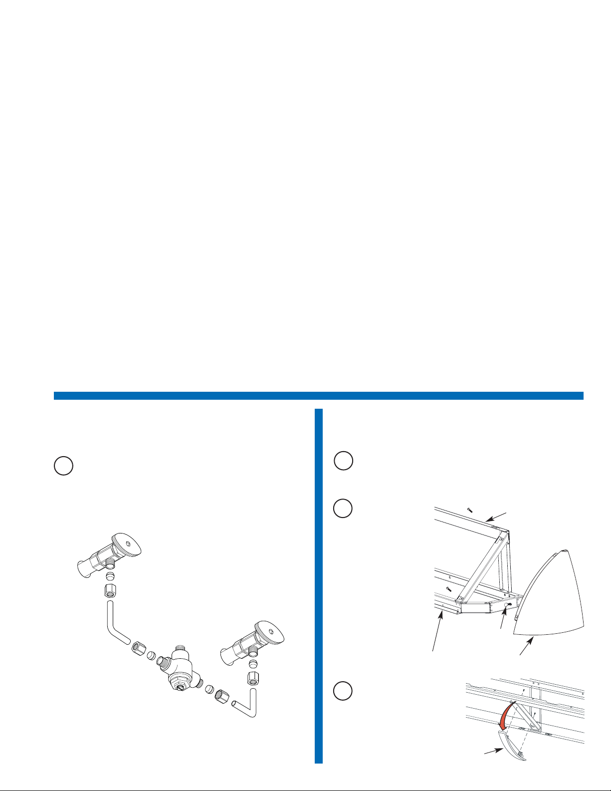
1
Install Thermostatic Mixing Valve
A
If there is no tempered water supply, install Thermostatic Mixing
Valve between hot and cold water supply.
3
2
Remove End Caps from Frame
Bottom Backside of Frame
Front of Frame
End Cap (2)
Enlarged Hole and
Slot in Frame
A
Loosen (do not remove) screws on inside of frame.
C
For triple station sinks,
remove the Front Panel
Support.
B
Remove both End
Caps by removing
the two outer screws
on each Cap. Slide
Cap forward in slot
and pull it out
through enlarged
hole in Frame.
Front Panel Support
Page 4
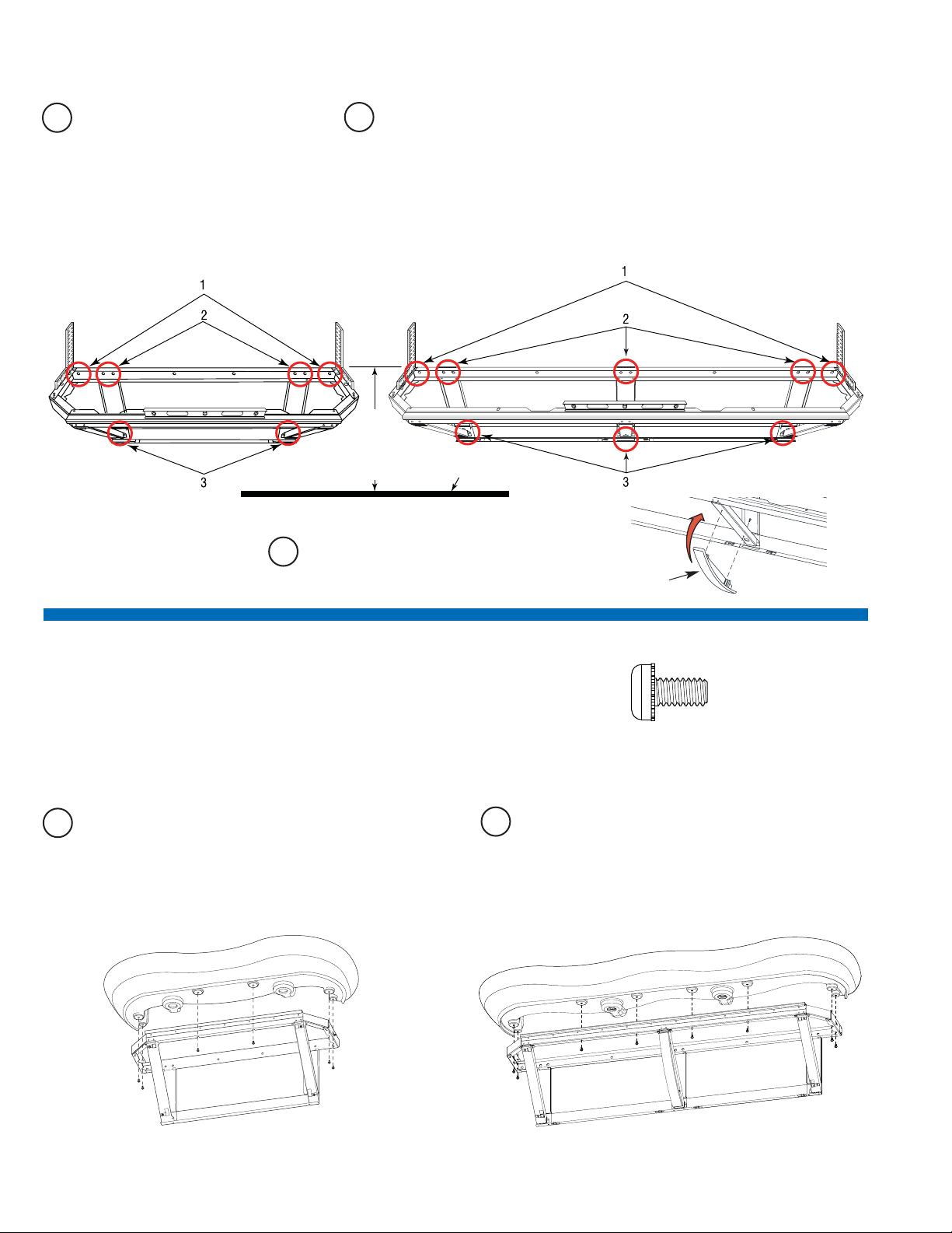
4
Mount Basin to Frame
A
Mount Basin to Frame using 1/4”-20 x 1/2” SEMS fasteners.
B
If desired, apply caulk between Basin and wall.
3
Mount Frame to Wall
4
Triple StationDouble Station
1/4”-20 x 1/2” Pan Head Screw (SEMS)
(Actual Size)
Note: If desired, Grid Strainers may be installed prior to mounting
Basin to the Frame. Refer to Step 5.
Triple Station
Double Station
FINISHED FLOOR
D
(See VARIABLE
MOUNTING
HEIGHT CHART
On Page 2)
C
For triple station sinks, reinstall the Front Panel
Support.
A
If desired, apply adhesive to back
surfaces of Frame.
B
Mount Frame to wall using 3/8" fasteners with 1000 lb min
pull out strength in the following locations:
1. Each hole in the extreme outer corners of top support
2. One of either of the two holes in the top position of each upright
3. The lower hole location in each upright
Fasteners may be optionally applied to any of the remaining mounting hole locations.
Level Frame in both directions before tightening fasteners securely.
Front Panel Support
Page 5
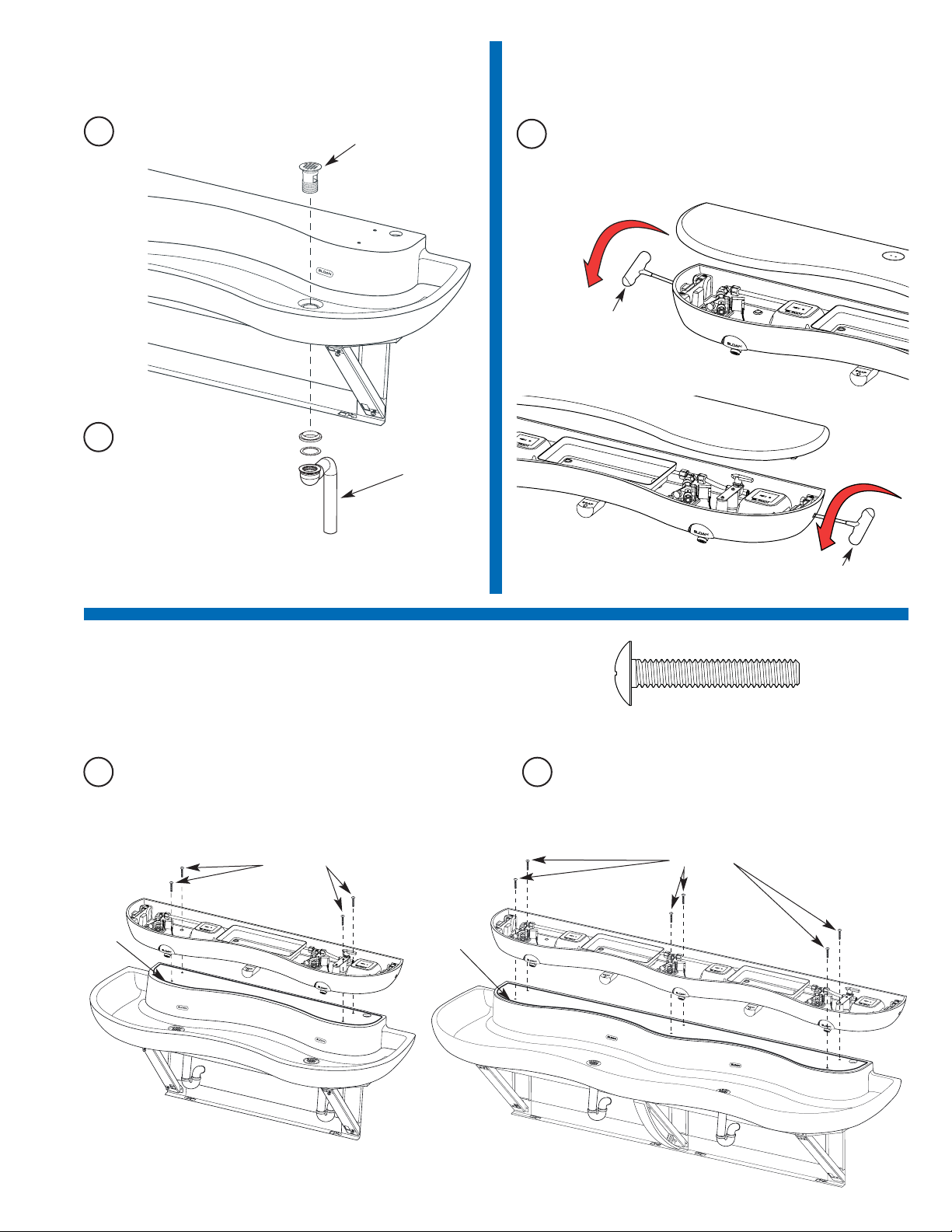
6
Remove Cover from Head
5
Install Grid Strainers and Connect
Drain Line
A
Insert T-Handled Wrench into access holes on left and right
sides of the Head. Turn top of wrench toward front of Head
rotating until it stops to fully open the latch. Remove the Cover.
A
Install Grid Strainers.
Drain Line
Grid Strainer
T-Handle
Wrench
T-Handle
Wrench
B
Plumb drain outlets to wall.
7
Mount Head to Basin
Fastener (4)
5
A
If desired, apply caulk between Basin and Head.
Bead of
Caulk
B
Mount Head to Basin using 1/4”-20 x 1-1/2” Truss Head
Screws.
Bead of
Caulk
Fastener (6)
Triple StationDouble Station
1/4”-20 x 1-1/2” Truss Head Screw
(Actual Size)
Page 6
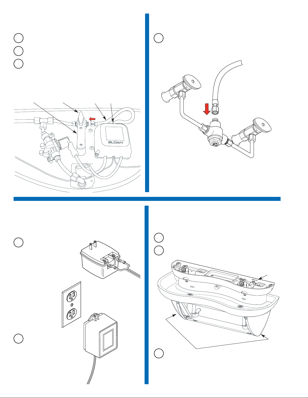
10
Connect Power Cable to
Transformer and Plug Transformer
into Receptacle
A
Connect Spade Terminals
on Power Cord to the
Transformer.
B
Drop Braided Hose Supply Line through service access hole.
C
Connect Braided Hose Supply Line to right side of Shut Off
Valve in Head.
Note: To ease Supply Line installation, remove the two screws
holding the Shut Off Valve Bracket. After connecting Supply Line,
reinstall the Shut Off Valve Bracket.
A
Drop Power Cord through service access hole.
8
Connect Supply Line to Shut Off
Valve in Head
SERVICE ACCESS
HOLE
BRAIDED HOSE
SUPPLY LINE
SHUT OFF
VALVE
9
Connect Supply Line to
Thermostatic Mixing Valve
A
Install water line.
6
B
Plug Transformer into
outlet.
11
Open Shut Off Valve, Turn on Water
Supply, Check for Water Leaks and
Install End Caps
A
Open Shut Off Valve and turn on water supply.
END CAP
C
Replace End Caps. Insert the screw located on the inside of the
Cap into the enlarged hole of the Frame. Then slide the Cap into
place. Loosely install the two front screws. Slide End Cap UP to
eliminate any gap between the End Cap and Basin. Tighten the
inside screw securely. Lastly, tighten the two front screws
securely. Follow the same procedure for the second End Cap.
B
Check all plumbing for water leaks.
Double Station Sink Shown
SHUT OFF VALVE
BRACKET
Shut Off
Valve
Page 7
Troubleshooting Guide
1. No water flows when sensor is activated
Ensure that main power supply is turned “ON.” Check receptacle,
transformer, solenoid, leads and connections.
If Sensor LED does not blink:
A. Control module circuit board is faulty; replace.
B. Sensor is faulty; replace sensor module.
If Sensor LED blinks when user is sensed:
A. Supply Stop(s) may be closed; open Supply Stop(s).
B. Debris may be in Solenoid filter; remove, clean and reinstall.
2. Very low flow or slow dribble
A. Supply Stop(s) may be closed; open Supply Stop(s).
B. Debris is in solenoid, won’t close properly; remove operator
and clean. Reassemble in the same manner.
C. Debris is in Solenoid filter; remove, clean and reinstall.
D. Debris is in spray head; remove, clean and reinstall.
3. Continues to run (even after power to faucet has been
disconnected)
A. Solenoid valve is installed backwards; install correctly.
B. Debris is in solenoid, won’t close properly; remove operator
and clean. Reassemble in the same manner.
7
Solenoid Screen Filter Cleaning
A
Before cleaning the Screen Filter, turn off the water supply at
supply stop(s).
B
Activate the Spray Head to relieve any pressure in the system.
D
Unscrew the Filter Cap and remove it from the Solenoid Valve
Housing.
E
Carefully remove the Screen Filter from the Solenoid Valve
Housing.
F
Clean the Screen Filter using fresh tap water only. If necessary,
use a small brush to clean. Use caution while cleaning to
prevent damage to Screen Filter.
G
Examine the Copper Washer for wear or damage; replace if
necessary. Carefully replace the Screen Filter into the Filter Cap.
Screw the Filter Cap with Copper Washer into the Solenoid
Valve Housing and tighten securely to prevent leaks.
H
Turn on the water supply at the supply stop(s). Activate the
Spray Head to purge any air from the system lines. Check for
leaks and repair as necessary.
C
Remove Cover as instructed in Step 6.
I
Install Cover as instructed in Step 12.
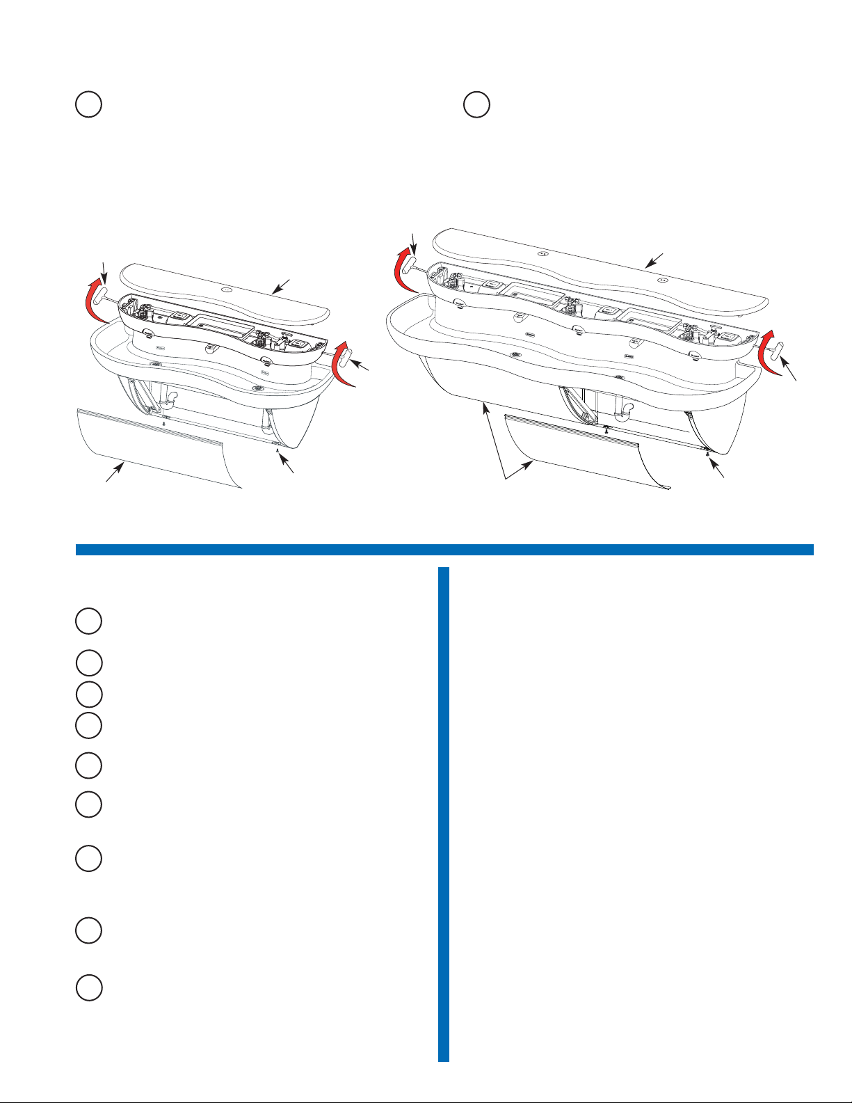
12
Install Cover and Front Panel(s)
A
Replace Cover and latch firmly in place with T-Handled Wrench
(Rotate top of handle toward wall until latch snaps into
position).
B
Replace Front Panel(s) by hanging top lip of Panel into track of
Trim Rail under Basin. Swing panel into position and affix with 2
Fasteners. Triple Station Models — repeat this procedure for
second panel.
Front Panel
Cover
T-Handle
Wrench
T-Handle
Wrench
Fastener (2)
Triple StationDouble Station
Front Panel (2)
Cover
T-Handle
Wrench
Fastener (4)
T-Handle
Wrench
Page 8
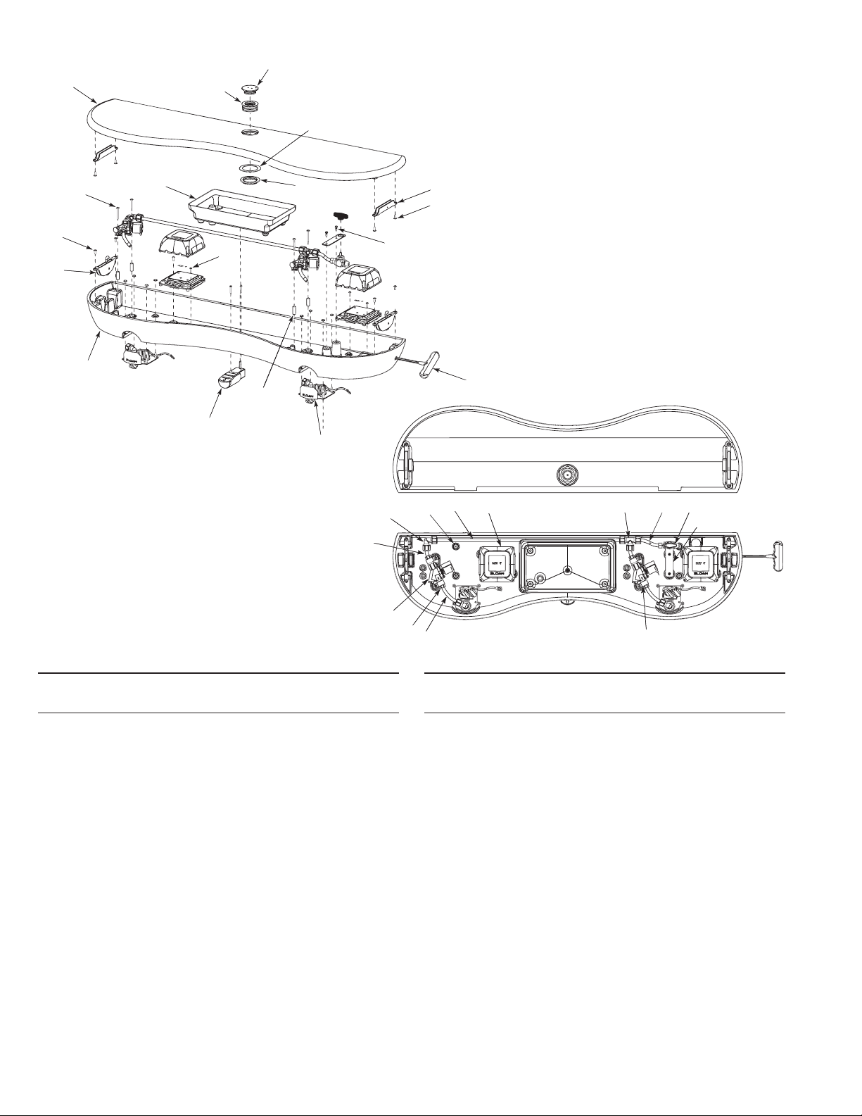
Item Part Description
No. No.
1 EW-46 Electronics Enclosure 2 Station Machined
2 EW-41 Large Latch (2)
3 EW-27 Screw, Flat Head #10-24 x 1/2” Long (4)
4 EW-75-A Sensor Plate Assembly (2)
5 EW-8 Spacer, #8 x 1” Long (4)
6 EW-13 Mounting Clamp for ETF-370-A Solenoid (4)
7 EW-9 Screw, Truss Head #8-32 x 1-1/2” Long (4)
8 ETF-61 Male Connector (4)
9 ETF-370-A Solenoid Valve Assembly (2)
10 EW-19 Compression Tee Fitting 3/8" Tube
11 EW-89-00362 Tube, 3/8" x 3-5/8” Long (2)
12 EW-89-00188 Tube, 3/8" x 1-7/8” Long (2)
13 EW-18 Compression Elbow Fitting, 3/8" Tube
14 EW-5 Mounting Bracket for Shut-off Valve
15 EW-74 Panel Mount Ball Valve - 3/8" Compression
Fitting
16 EW-36 Screw, Pan Head #8-32 x 7/16” Long (SEMS)(2)
17 EW-89-02525 Tube, 3/8" x 25-1/4” Long
18 EW-89-00388 Tube, 3/8" x 3-7/8” Long
19 ETF-450-A Splash Proof Junction Box Assembly (2)
20 EW-28 Screw, Round Head #8-32 x 1/2” Long (4)
21 † ESD-255-A Manual Soap Pump Assembly
Item Part Description
No. No.
22 † ESD-245-A Manual Soap Reservoir Assembly
23 EW-37 Screw, Truss Head 1/4-20 x 1-1/2” (4)
— EW-26 Tube Support 3/8" (5) (Not Shown)
— MIX-135-A Thermostatic Mixing Valve (Below Deck)
(Not shown)
— EW-87 Flexible Supply Hose, 2 Station (Not Shown)
— EW-82-A Wiring Harness, 2 Station (Not Shown)
— ETF-233 Transformer (Not shown)
— ETF-731 Vandal Proof Key, Standard and Junior
(Not shown)
24 EW-96 T-Handle Hex Wrench, 7/32"
25 EW-48-X Cover, Electronics Enclosure, 2 Station Machined
26 EW-42 Large Encased Receiver (2)
27 EW-27 Screw, Flat Head #10-24 x 1/2” Long (4)
28 ‡ ESD-242 Sleeve for Fill Cap
29 ‡ ESD-241 Fill Cap for Soap Reservoir
30 ‡ EW-11 Gasket - Fill Cap Sleeve (Manual Soap Reservoir)
31 ‡ ESD-243 Jam Nut for Fill Cap Sleeve
— ‡ ESD-249 Fill Cap Spanner (Not Shown)
† Included on models with Soap Dispenser.
‡ Included on models with Fill Cap.
25
28
26
30
29
27
22
31
7
3
2
1
20
21
5
4
24
16
13
17
19
10
15
14
6
11
8
9
12
Parts List
8
23
18
EW-72000 Double Station Head Assembly
Page 9
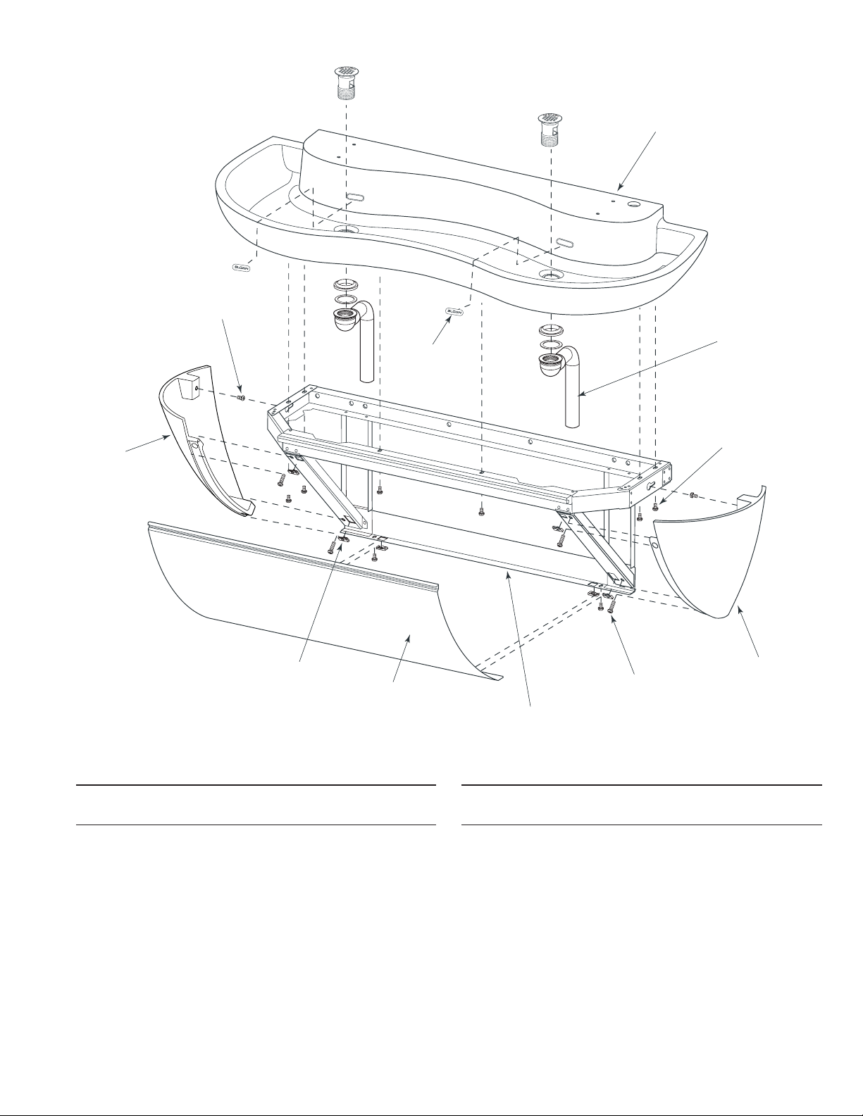
Item Part Description
No. No.
1 EW-20-A Cabinet Weldment, 2 Station
2 EW-99 U-Type Nut Standard 1/4-20 Thread (6)
3 EW-60 End Cap Right - Machined
4 EW-52 End Cap Left - Machined
5 EW-15 Screw, Pan Head 1/4-20 x 1/2” Long (SEMS) (4)
6 EW-16 Screw, Pan Head 1/4-20 x 1” Long (SEMS) (4)
7 EW-25 Front Panel, 2 Station
Item Part Description
No. No.
8 EW-44 Basin 2-Station Machined
9 ETF-725-A Grid Strainer Assembly (2)
10 EW-15 Screw, Pan Head 1/4-20 x 1/2” Long (SEMS) (6)
11 EW-61 Overflow Cover Plate (2)
— EW-98 Light Duty Buffing Pad (Not Shown)
Parts List
8
9
10
3
6
1
7
2
4
5
11
9
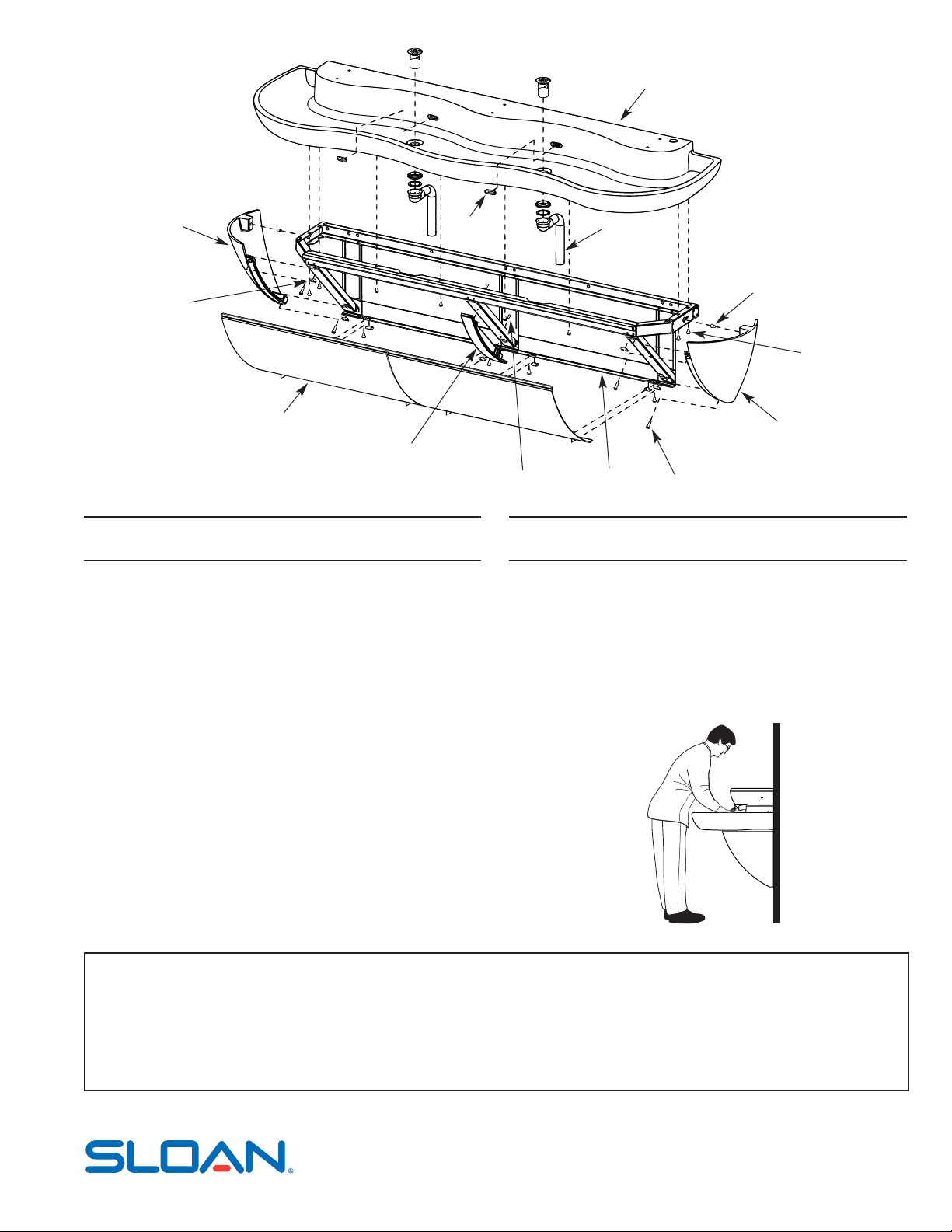
EW-72000 Double Station Cabinet and Basin Assemblies
Page 10
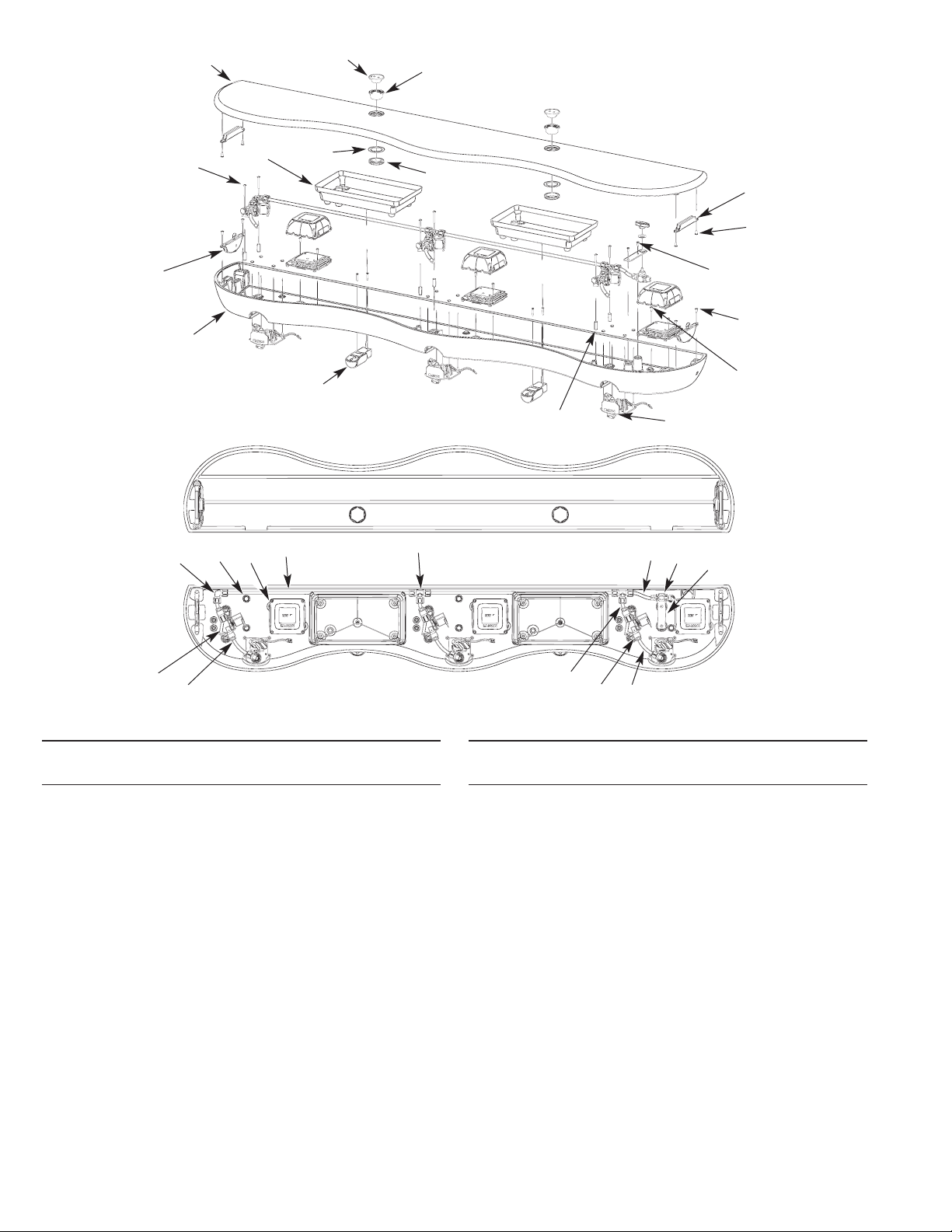
25
27
29
24
1
12
9
5
20
3
Parts List
Item Part Description
No. No.
1 EW-56 Electronics Enclosure, 3 Station Machined
2 EW-41 Large Latch (2)
3 EW-27 Screw, Flat Head #10-24 x 1/2” Long (4)
4 EW-75-A Sensor Plate Assembly (3)
5 EW-8 Spacer #8 x 1” Long (6)
6 EW-13 Mounting Clamp ETF-370-A Solenoid (6)
7 EW-9 Screw, Truss Head #8-32 x 1-1/2” Long (6)
8 ETF-61 Male Connector (6)
9 ETF-370-A Solenoid Valve Assembly (3)
10 EW-89-00362 Tube 3/8” x 3-5/8” Long (3)
11 EW-89-00188 Tube 3/8” x 1-7/8” Long (3)
12 EW-19 Compression Tee Fitting 3/8” Tube (2)
13 EW-18 Compression Elbow Fitting 3/8” Tube
14 EW-89-02525 Tube 3/8” x 25-1/4” Long (2)
15 EW-89-00388 Tube 3/8” x 3-7/8” Long (1)
16 EW-5 Mounting Bracket for Shut-off Valve
17 EW-36 Screw, Pan Hd #8-32 x 7/16” Long (SEMS) (2)
18 EW-74 Panel Mount Ball Valve - 3/8” Compression
Fitting
19 ETF-450-A Splash Proof Junction Box Assembly (3)
20 EW-28 Screw, Round Head #8-32 x 1/2” Long (6)
21 † ESD-255-A Manual Soap Pump Assembly (2)
Item Part Description
No. No.
22 † ESD-245-A Soap Reservoir Assembly (2)
23 EW-37 Screw, Truss Head 1/4-20 x 1-1/2” Long (6)
(Not Shown)
— EW-26 Tube Support 3/8” (7) (Not Shown)
— MIX-135-A Thermostatic Mixing Valve (Below Deck)
(Not Shown)
— EW-92-A Wiring Harness 3 Station (Not Shown)
— ETF-233 Transformer (Not Shown)
— ETF-731 Vandal Proof Key, Standard and Junior (Not
Shown)
— EW-97 Flexible Supply Hose, 3 Station (Not Shown)
— EW-96 T-Handle Hex Wrench 7/32” (Not Shown)
24 EW-58-X Cover, Electronics Enclosure, 3 Station Machined
25 EW-42 Large Encased Receiver (2)
26 EW-27 Screw, Flat Head #10-24 x 1/2” Long (4)
27 ‡ ESD-242 Sleeve for Fill Cap (2)
28 ‡ ESD-241 Fill Cap for Soap Reservoir (2)
29 ‡ EW-11 Gasket for Fill Cap Sleeve (2)
30 ‡ ESD-243 Jam Nut for Fill Cap Sleeve (2)
— ‡ ESD-249 Fill Cap Spanner (Not Shown)
† Included on models with Soap Dispenser.
‡ Included on models with Fill Cap.
10
28
26
17
4
30
22
2
21
14
19
13
8
11
6
10
15
18
16
7
EW-73000 Triple Station Head Assembly
23
Page 11
The information contained in this document is subject to change without notice.
When assistance is required, please contact Sloan Valve Company Installation Engineering Department at:
1-888-SLOAN-14 (1-888-756-2614)
OR
1-847-233-2016
11
13
6
4
9
2
3
1
7
5
12
8
Parts List
Item Part Description
No. No.
1 EW-30-A Cabinet Weldment, 3 Station
2 EW-50 Front Panel Support - Machined
3 EW-36 Screw, Pan Head #8-32 x 7/16” Long (SEMS) (2)
4 EW-99 U-type Nut, Standard 1/4-20 Thread (8)
5 EW-60 End Cap Right - Machined
6 EW-52 End Cap Left - Machined
7 EW-16 Screw, Pan Head 1/4-20 x 1” Long (SEMS) (4)
Item Part Description
No. No.
8 EW-15 Screw, Pan Head 1/4-20 x 1/2” Long (SEMS) (2)
9 EW-35 Front Panel, 3 Station (2)
10 EW-54 Triple Station Lavatory Basin Assembly
11 ETF-725-A Grid Strainer Assembly (2)
12 EW-15 Screw, Pan Head 1/4-20 x 1/2” Long (SEMS) (8)
13 EW-61 Overflow Cover Plate (2)
— EW-98 Light Duty Buffing Pad (Not Shown)
Operation
As the user’s hands pass under the spray head and enter the beam’s effective
range, the beam is reflected back into the sensor receiver and activates the
solenoid valve allowing water to flow from the Spray Head. Water will flow until
the user’s hands are removed from under the Spray Head or until the automatic
time out limit setting is reached.
SLOAN VALVE COMPANY • 10500 Seymour Avenue • Franklin Park, IL 60131
Phone: 1-800-9-VALVE-9 or 1-847-671-4300 • Fax: 1-800-447-8329 or 1-847-671-4380
www.sloanvalve.com
Printed in the U.S.A. 03-07
Copyright © 2007 SLOAN VALVE COMPANY
EW-73000 Triple Station Cabinet and Basin Assemblies
10
 Loading...