

Sloan HYB-1000-RET Installation Manual
1
1
2
3
4
A
A
2
43
®
HYB-1000-RET
RETROFIT HYBRID URINAL
with Jetrinse Solution Technology
INSTALLATION INSTRUCTIONS
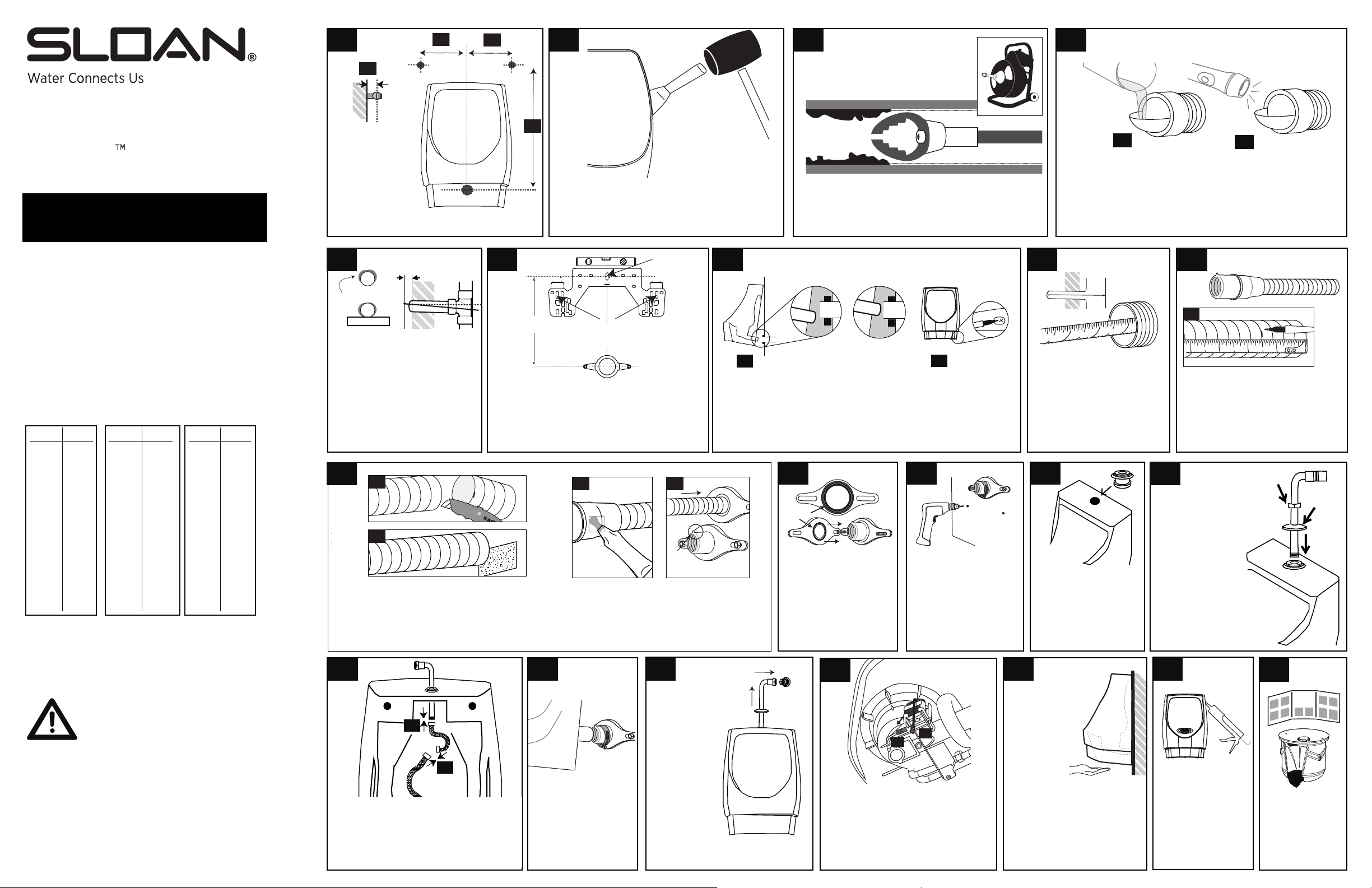
BEFORE STARTING INSTALLATION:
•
IMPORTANT Do not install on copper DWV
due to copper’s susceptibility to corrosion.
Check rough-in height to achieve 24” rim height
•
(17” rim height for ADA).
•
Check slope. Downhill slope, per code, is essential
because waterfree urinals depend on gravity flow.
•
Check DWV material. Suitable materials include
cast iron, PVC, ABS and galvanized steel.
•
Shut o water supply and remove flush valve and
vacuum breakers.
TUBE CUTTING CHART
•
Measure drain nipple depth (inches) to find trim
length (inches)
13 7/8” or more DO NOT CUT
•
3 3/4” or less DO NOT USE TUBE
•
OR LESS TRIM
13 ¾" ¼"
13 ½ ½
13 ¼ ¾
13 1
12 ¾ 1¼
12 ½ 1½
12 ¼ 1¾
12 2
11 ¾ 2¼
11 ½ 2½
11 ¼ 2¾
11 3
10 ¾ 3 ¼
10 ½ 3 ½
CUSTOMER CARE
1-800-982-5839
customer.service@sloanvalve.com
OR LESS TRIM
10 ¼" 3 ¾"
10 4
9 ¾ 4 ¼
9 ½ 4 ½
9 ¼ 4 ¾
9 5
8 ¾ 5 ¼
8 ½ 5 ½
8 ¼ 5 ¾
8 6
7 ¾ 6 ¼
7 ½ 6 ½
7 ¼ 6 ¾
7 7
OR LESS TRIM
6 ¾"
6 ½
6 ¼
6
5 ¾
5 ½
5 ¼
5
4 ¾
4 ½
4 ¼
4
7 ¼ "
7 ½
7 ¾
8
8 ¼
8 ½
8 ¾
9
9 ¼
9 ½
9 ¾
10
C
Confirm existing
supply stop and
drainline fall
within these
ranges:
A. 41/4” to 51/4”
1/2” to 351/2”
B. 28
1/8” to 3”
C. 2
5
Cut away wall
Lift drain line & brace
with mending plate
Adjust drain to achieve pitch
1/2” to 3/4”*
only if standing water is present
(code requires 1/4” drop per
foot of drain line for proper
pitch). Seal wall according to
code. IMPORTANT Nipple must
not extend more than 3/4” past
finished wall.
9
B
C
B. Cut the tube at the groove using a
sharp utility knife to ensure a square,
flat cut.
C. Clean burrs from the cut end by
using emery paper.
14
B
Use utility knife to cut caulk then use a putty
knife and mallet to remove the bowl. Remove
hanger brackets, scrape o caulk, and clean the
wall. Ensure the threads on the control stop are
brushed clean.
6
21 ½”
Measure and mark the rough-in if in-wall
carrier is not used. Use a 5/16” masonry bit to
drill hole, then install the hanger bracket with
one plastic anchor and screw. Level the bracket
then mark, drill and install two additional
plastic anchors and screws.
Install additional
screws here
D
LUBRICANT
D. Apply lubricant to the outside of the
rubber bushing and ribbed inside area.
E. Insert tube and bushing IMPORTANT
Be sure arrow tab is at the 12:00 position
Install plastic
anchor and
screw here
E
Arrow
tab UP
.
and lip seats against flange.
15
16
2" side cutter blade
IMPORTANT: Use a drain machine to remove
build-up inside pipes. Clean up to 25 feet deep
then flush with water to remove cutting debris.
Never install on copper DWV.
7
INCORRECT
Not centered
A
A. Hang bowl on the bracket and check tail pipe alignment, then
remove the bowl and adjust the bracket as needed. Re-hang
and re-check bowl alignment with the drain line. Tail pipe should
align with center of drain line. B. Mark anchor holes then remove
bowl without moving hanger bracket.
10
Seal
Place the seal into the
flange with ribs facing
out. Install the flange
with washers and hex
nuts, but do not over
tighten.
CORRECT
Centered
B
11
Drill holes
with 5/16” masonry bit
for the lower anchor
screws and insert
plastic anchors. Install
hose clamp with screw
at bottom, but do not
tighten.
from step 7B
17
A. Clean Face of drain nipple.
B. Install the clear inspection disc with the compression nut.
C. Slowly pour water into the drain.
D. Use a flashlight to check the pitch/slope no water
should be present in the inspection disc or nipple.
E. Remove disc and nut after inspection.
8
10
11
1 2
Determine the drain nipple
length by measuring the
distance between the back
of the sanitary tee (or elbow)
the front edge of the
nipple.
12
With urinal on the floor,
insert rubber grommet
into the hole located at
the top of the urinal.
Be sure the larger
diameter side is facing
up and fully seated.
18
C
8
9
A
D
1234
A. Find the drain nipple depth on
the Tube Cutting Chart (left).
Measure and mark the specified
trim length on the insert tube at
the nearest 1/4” groove.
13
Slide coupling nut
with threads facing
up and escutcheon
plate onto supply
assembly as shown,
then push threaded
end through
grommet so end is
accessible from
backside of urinal.
NOTE Use soap or
excess lubricant from
step 9D to ease
insertion.
19
coupling
nut
20
escutcheon
plate
CAUTION After removing any urinal from the
drain line, it’s normal for certain naturally occurring,
but potentially hazardous sewer gases to escape
through the opening until the waterless cartridge
is installed properly into the waterless urinal. If you
removing the urinal from the wall, temporarily wedge paper towels or a
rag into the drain hole to reduce any outflow of sewer gases, and remove
per towels or rag prior to completing the urinal or cartridge
the pa
installation. Never smoke, have an open flame, or place your nose or
mouth near open drain lines or waterless urinal housings into which
a car tridge is not yet pro perly installed. You also can wear a breathing
mask when removing or installing any waterless urinal or cartridge to
reduce potential exposure to any such gases.
www.SloanValve.com
The information in this document is subject to change without notice.
© 2016 Sloan Valve Company All rights reserved.
Code No. 0816682 (01-16 Rev 1)
need to leave an open drain line unattended after
A
B
A. Securely connect the female end of the
loose braided hose to the end of the
supply assembly. B. Connect the male end
to the braided hose on the Hybrid Jetrinse
assembly on the urinal. NOTE Ensure that
these connections are tight and leak-free.
Hang the bowl
inserting tailpipe into
bushing, and tighten
hose clamp. Install 2
lower anchor screws
with washers.
Rotate and
raise the
supply
assembly and
insert into
supply stop.
Tighten
coupling nut
securely. Do
NOT turn on
water yet.
A
B
Connect battery A to wire B. After 1
minute turn on water at supply stop
and confirm there are no connection
leaks.
Wave hand under
IR switch to
activate test
rinse and
ensure there
is no standing
water in
housing. System will
operate automatically
every 72 hours from
battery activation. NOTE
System will pause for 2
minutes after 2 manual
rinse activations.
Caulk the bowl
to the wall if
there is good
flow and no
leaks or standing
water in housing.
CARTRI DGE
INSTRUCTIO NS
Install cartridge
per the cartridge
instruction sheet.
 Loading...