

Sloan Foot Pedal Flushometer User Manual
Code No. 0816488
Rev. 0 (08/08)
INSTALLATION INSTRUCTIONS FOR
FOOT PEDAL ACTIVATED WATER CLOSET AND URINAL FLUSHOMETERS
LIMITED WARRANTY
Sloan Valve Company warrants its Sloan Flushometers to be made of first class materials, free from defects of material or workmanship under normal use and to perform the
service for which they are intended in a thoroughly reliable and efficient manner when properly installed and serviced, for a period of three years (1 year for special finishes)
from date of purchase. During this period, Sloan Valve Company will, at its option, repair or replace any part or parts which prove to be thus defective if returned to Sloan
Valve Company, at customer’s cost, and this shall be the sole remedy available under this warranty. No claims will be allowed for labor, transportation or other incidental
costs. This warranty extends only to persons or organizations who purchase Sloan Valve Company’s products directly from Sloan Valve Company for purpose of resale.
THERE ARE NO WARRANTIES WHICH EXTEND BEYOND THE DESCRIPTION ON THE FACE HEREOF. IN NO EVENT IS SLOAN VALVE COMPANY RESPONSIBLE
FOR ANY CONSEQUENTIAL DAMAGES OF ANY MEASURE WHATSOEVER.
PRIOR TO INSTALLATION
Before installing the Sloan Flushometer, be sure the items listed below are
installed. Also, refer to the rough-in diagrams on Page 2.
• Closet/urinal fixture
• Drain line
• Water supply line
• Drill holes in wall for foot pedal actuator and water inlet to fixture
Due to code restrictions and installation practices, the Crown Naval 313
INT’L is for International use only.
Important:
• INSTALL ALL PLUMBING IN ACCORDANCE WITH APPLICABLE CODES
AND REGULATIONS.
• WATER SUPPLY LINES MUST BE SIZED TO PROVIDE AN ADEQUATE
VOLUME OF WATER FOR EACH FIXTURE.
• FLUSH ALL WATER LINES PRIOR TO MAKING CONNECTIONS.
Most Low Consumption water closets (1.6 gallon/6.0 liter) require a
minimum flowing pressure of 25 psi (172 kPa).
The Sloan Flushometer is designed to operate with 15 to 100 psi (104 to
689 kPa) of water pressure. THE MINIMUM PRESSURE REQUIRED TO THE
VALVE IS DETERMINED BY THE TYPE OF FIXTURE SELECTED. Consult
fixture manufacturer for minimum pressure requirements.
Most Low Consumption water closets (1.6 gpf/6.0 Lpf) require a minimum
flowing pressure of 25 psi (172 kPa).
Protect the Chrome or Special finish of this Flushometer — DO NOT USE
TOOTHED TOOLS TO INSTALL OR SERVICE THE VALVE. Also, see "Care and
Cleaning" section of this manual.
IMPORTANT: EXCEPT FOR CONTROL STOP INLET, DO NOT USE PIPE
SEALANT OR PLUMBING GREASE ON ANY VALVE COMPONENT OR
COUPLING!
TOOLS REQUIRED FOR INSTALLATION
• Straight blade screwdriver for stop adjustment (exposed models only)
• Sloan A-50 Super-Wrench™, Sloan A-109 Plier Wrench or smooth jawed
spud wrench
• Hole saw for foot pedal actuator and water inlet to fixture
• 1/16” hex wrench for supply flange (exposed models only)
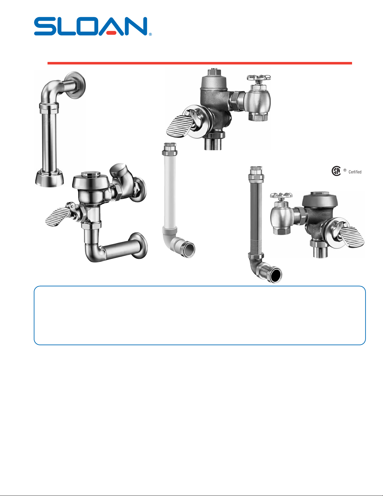
Royal 310
Exposed Model Shown
Royal, Regal, and
Crown Naval
Models 310, 312, 313, 313 INT’L,
318, 320, 323 and 343
Exposed and Concealed
Foot Pedal Activated
Closet and Urinal
Flushometer Valves
Royal 313
Concealed Model Shown
Crown Naval 313 INT’L
Concealed Model Shown
Made in the U.S.A.
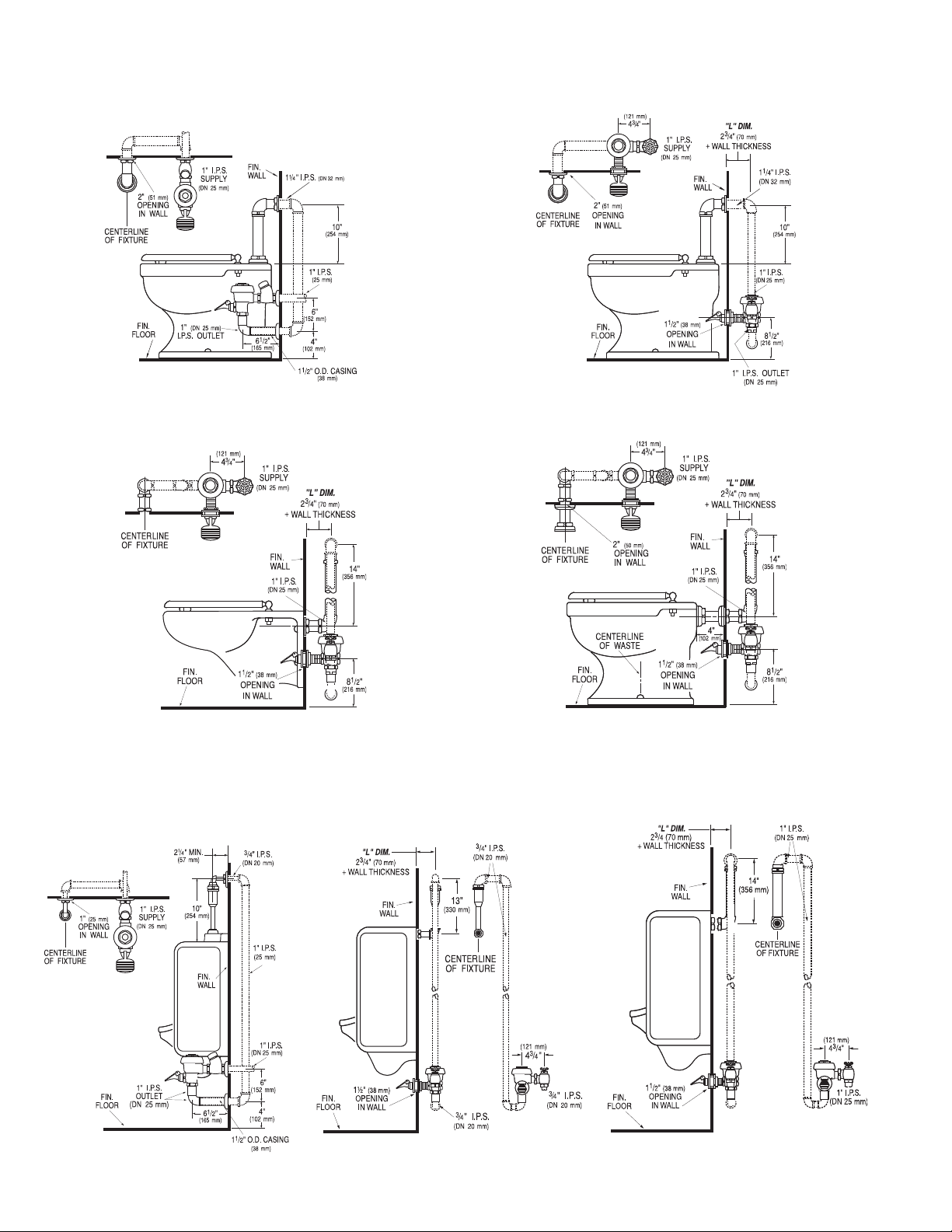
WATER CLOSET ROUGH-IN
2
URINAL ROUGH-IN
Model 310 — Water Saver (3.5 gpf/13.2 Lpf)
Model 310-1.6 Low Consumption (1.6 gpf/6.0 Lpf)
Model 312 — Water Saver (3.5 gpf/13.2 Lpf)
Model 312-1.6 Low Consumption (1.6 gpf/6.0 Lpf)
Model 313 — Water Saver (3.5 gpf/13.2 Lpf)
Model 313-1.6 Low Consumption (1.6 gpf/6.0 Lpf)
Model 318 — Water Saver (3.5 gpf/13.2 Lpf)
Model 318-1.6 Low Consumption (1.6 gpf/6.0 Lpf)
Model 320 — Water Saver (1.5 gpf/5.7 Lpf)
Model 320-1.0 Low Consumption (1.0 gpf/3.8 Lpf)
Model 323 — Water Saver (1.5 gpf/5.7 Lpf)
Model 323-1.0 Low Consumption (1.0 gpf/3.8 Lpf)
Model 343 — Water Saver (1.5 gpf/5.7 Lpf)
Model 343-1.0 Low Consumption (1.0 gpf/3.8 Lpf)
Note: Flush Connections shown in dotted lines not included
Note: Flush Connections shown in dotted lines not included
3
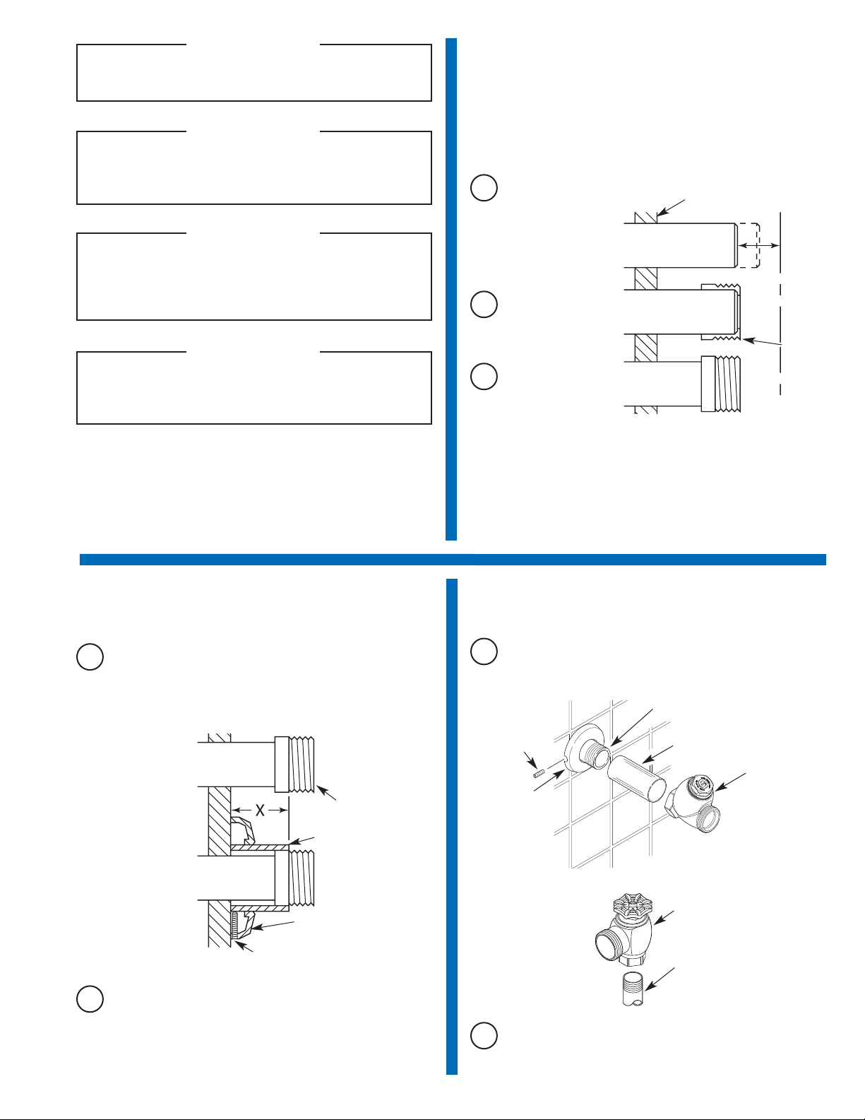
1
Install Optional Sweat Solder
Adapter (only if your supply pipe
does not have a male thread)
2
Install Cover Tube and Wall Flange
to supply pipe
With the exception of Control Stop Inlet, DO NOT use pipe
sealant or plumbing grease on any valve component or
coupling!
!!! IMPORTANT !!!
Protect the chrome or special finish of Sloan Flushometers —
DO NOT USE toothed tools to install or service these valves.
Use a Sloan A-50 Super-Wrench™, Sloan A-109 Plier Wrench
or smooth jawed spud wrench to secure all couplings. Also
see “Care and Cleaning” section of this manual.
!!! IMPORTANT !!!
This product contains mechanical and/or electrical
components that are subject to normal wear. These
components should be checked on a regular basis and
replaced as needed to maintain the valve’s performance.
!!! IMPORTANT !!!
If you have questions about how to install your Sloan
Flushometer, consult your local Sloan Representative or call
Sloan Installation Engineering Department at:
1-888-SLOAN-14 (1-888-756-2614) OR 1-847-233-2016
A
Measure from finished
wall to C/L of Fixture
Spud. Cut pipe 1¼"
(32 mm) shorter than
this measurement.
Chamfer O.D. and I.D.
of water supply pipe.
WATER SUPPLY PIPE
FINISHED WALL
1-1/4”
(32 mm)
C/L OF
FIXTURE
SPUD
SWEAT
SOLDER
ADAPTER
B
Slide Threaded Adapter
fully onto pipe.
C
Sweat solder the
Adapter to pipe.
Thread Control Stop onto supply pipe. Tighten with a wrench until
outlet is positioned as required.
WATER
SUPPLY PIPE
SWEAT
SOLDER ADAPTER
COVER TUBE
WALL
FLANGE
SET SCREW
A
Measure from finished wall to first thread of Adapter or threaded
supply pipe (dimension “X”). Cut Cover Tube to this length.
B
Slide Cover Tube over pipe. Slide Wall Flange over Cover Tube
until against wall.
A
Tighten Set Screw with a 1/16” hex wrench. For Exposed
Flushometers — DO NOT install Vandal Resistant Stop Cap at this
time.
B
3
Install Control Stop
CONCEALED
EXPOSED
SET
SCREW
SUPPLY
FLANGE
IRON PIPE NIPPLE OR COPPER PIPE
WITH SWEAT SOLDER ADAPTER
COVERING
TUBE
BAK-CHEK
®
CONTROL
STOP
BAK-CHEK
®
CONTROL STOP
IRON PIPE NIPPLE OR
COPPER PIPE WITH
SWEAT SOLDER
ADAPTER
Never open Control Stop to where the flow from the valve
exceeds the flow capability of the fixture. In the event of a
valve failure, the fixture must be able to accommodate a
continuous flow from the valve.
!!! IMPORTANT !!!
 Loading...