

Sloan EW-62050 Installation Manual
Code No. 0816836
Rev. 0 (07/09)
INSTALLATION INSTRUCTIONS FOR DOUBLE AND TRIPLE STATION
SENSOR ACTIVATED SOLID SURFACE LAVATORY SYSTEMS
LIMITED WARRANTY
Sloan Valve Company warrants its EW-60000 Series Lavatory Systems to be made of first class materials, free from defects of material or workmanship
under normal use and to perform the service for which they are intended in a thoroughly reliable and efficient manner when properly installed and serviced,
for a period of three years (1 year for special finishes) from date of purchase. During this period, Sloan Valve Company will, at its option, repair or replace
any part or parts which prove to be thus defective if returned to Sloan Valve Company, at customer’s cost, and this shall be the sole remedy available under
this warranty. No claims will be allowed for labor, transportation or other incidental costs. This warranty extends only to persons or organizations who purchase
Sloan Valve Company’s products directly from Sloan Valve Company for purpose of resale. This warranty does not cover the life of the batteries (battery powered
models).
THERE ARE NO WARRANTIES WHICH EXTEND BEYOND THE DESCRIPTION ON THE FACE HEREOF. IN NO EVENT IS SLOAN VALVE COMPANY
RESPONSIBLE FOR ANY CONSEQUENTIAL DAMAGES OF ANY MEASURE WHATSOEVER.
EW-62000
EW-62050
Double Station
Sensor Activated
Solid Surface Lavatory System
EW-63000
EW-63050
Triple Station
Sensor Activated
Solid Surface Lavatory System
EW-62000-XX-X-MSD Model Shown
EW-63000-XX-X-MSD Model Shown
2
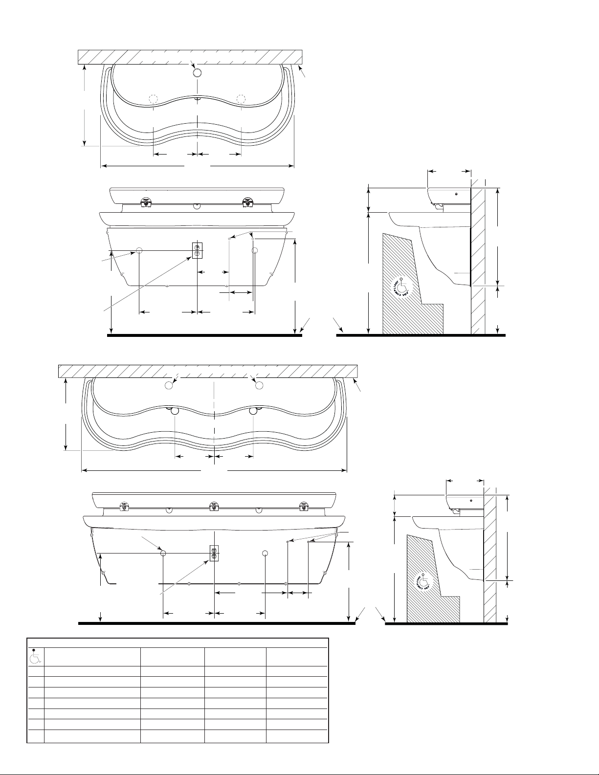
LAVATORY SYSTEM ROUGH-IN
MODEL EW-62000
MODEL EW-62050
Double Station Lavatory System
Flow Rate: 0.5 gpm/1.9 Lpm Max. Spray
Lavatory System Weight (Packaged):
Approximately 82 Lbs/37 Kg
MODEL EW-63000
MODEL EW-63050
Triple Station Lavatory System
Flow Rate: 0.5 gpm/1.9 Lpm Max. Spray
Lavatory System Weight (Packaged):
Approximately 124 Lbs/56 Kg
VARIABLE MOUNTING HEIGHT CHART (2 AND 3 STATION)
DIMENSION T.A.S. † T.A.S. † A.D.A.
DESCRIPTION AGES 4-10 AGES 11-15 STANDARD
A ROUGH-IN, DRAIN 20” (508 mm) 22” (559 mm) 24” (610 mm)
B ROUGH-IN, SUPPLY 23” (584 mm) 25” (635 mm) 27” (686 mm)
C RECOMMENDED RIM HEIGHT 29-3/4” (756 mm) 31-3/4” (806 mm) 33-3/4” (857 mm)
D FLOOR CLEARANCE, 2 STATION 11-1/8” (283 mm) 13-1/8” (333 mm) 15-1/8” (384 mm)
D FLOOR CLEARANCE, 3 STATION 12-1/16” (306 mm) 14-1/16” (357 mm) 16-1/16” (408 mm)
E BRACKETS, HEIGHT ‡ 25-3/4” (654 mm) 27-3/4” (705 mm) 29-3/4” (756 mm)
F BRACKETS, TOP HOLE ‡ 25” (635 mm) 27” (686 mm) 29” (737 mm)
† When no mirror is required above the basin.
‡ Refer to Step 2.
21”
(533 mm)
1-1/2”
(38 mm)
DRAIN (2)
110 VOLT,
60 Hz ,
15 AMP, GFCI
PROTECTED
ELECTRICAL
OUTLET
(BY OTHERS)
A
(SEE
CHART)
OPTIONAL LIQUID SOAP DISPENSER FILL
11-1/4”
(286 mm)
PLASTIC
CABINET
14-3/4”
(375 mm)
CENTERLINE
(286 mm)
50”
(1270 mm)
8-1/4”
(210 mm)
(152 mm)
C/L OF
DRAIN
11-1/4”
6 ”
14-3/4”
(375 mm)
C/L OF
DRAIN
FACE
OF
WALL
HOT/COLD
SUPPLY LINES
B
(SEE CHART)
1/2”
FINISHED
FLOOR
6-5/16”
(160 mm)
C
(SEE
CHART)
11-1/8”
(283 mm)
PLASTIC
CABINET
24-7/8”
(632 mm)
D
(SEE
CHART)
OPTIONAL LIQUID SOAP DISPENSER FILL
21”
(533 mm)
1-1/2” (38 mm)
DRAIN (2)
110 VOLT, 60 Hz,
A
(SEE
CHART)
15 AMP, GFCI
PROTECTED
ELECTRICAL
OUTLET
(BY OTHERS)
11-1/4”
(286 mm)
14-3/4”
(375 mm)
CENTERLINE
(286 mm)
76”
(1930 mm)
11-1/4”
PLASTIC
CABINET
21-1/4”
(540 mm)
14-3/4”
(375 mm)
6”
(152 mm)
FACE
OF
WALL
6-5/16”
(160 mm)
1/2”
HOT/COLD
SUPPLY LINES
C
(SEE
CHART)
B
(SEE CHART)
FINISHED
FLOOR
11-1/8”
(283 mm)
PLASTIC
CABINET
24”
(610 mm)
D
(SEE
CHART)
3
PRIOR TO INSTALLATION
Prior to installing the Sloan EW-60000 Series Lavatory System, install
the items listed below. Also, refer to the appropriate rough-in diagram on
Page 2 and brackets diagram on Page 4.
• Install electrical receptacle(s) for plug-in transformer(s) — 120 VAC,
2 amp service for each SFP-36 (6 VDC, 2300 mA) plug-in transformer
used (EW-62000/EW-63000 only).
• Hot and cold water supply lines or tempered water supply line (If there
is no tempered water supply, install mechanical mixing valve between
hot and cold water supply)
• Drain lines
Important:
• ADEQUATE STRUCTURAL SUPPORT IN OR BEHIND THE WALL IS
REQUIRED. REFER TO THE APPROPRIATE ROUGH-IN DIAGRAM ON
PAGE 2 FOR DRY WEIGHT OF SINK. STRUCTURAL SUPPORT
MUST HAVE A MINIMUM PULLOUT RATING OF 1000 POUNDS
(450 Kg) FOR EACH FASTENER.
• INSTALL ALL ELECTRICAL WIRING IN ACCORDANCE WITH
NATIONAL/LOCAL CODES AND REGULATIONS.
• INSTALL ALL PLUMBING IN ACCORDANCE WITH APPLICABLE CODES
AND REGULATIONS.
• USE APPROPRIATE PRECAUTIONS WHILE CONNECTING
TRANSFORMER TO 120 VAC POWER SOURCE.
• DO NOT PLUG TRANSFORMER INTO POWER SOURCE (RECEPTACLE)
UNTIL ALL WIRING IS COMPLETED.
• BEFORE CONNECTING FLEX HOSES TO SUPPLY STOPS, FLUSH ALL
WATER LINES UNTIL WATER IS CLEAR.
TOOLS REQUIRED FOR INSTALLATION
• Electric drill for drilling anchor holes.
• Standard sockets and open-end wrench set for installing anchoring
fasteners and connecting water lines.
• Pipe wrench for installing drain lines.
• Phillips and straight blade screwdrivers.
• Tubing Cutter
• Level
• Carpenter’s square
• Caulk gun
SINK LOCATION
Determine the appropriate wall location for the Lavatory System.
Consider that hot and cold water supply lines, drain lines, and an
electrical source (receptacle) will be required. Compare the physical
dimensions of the Lavatory System to the space available for the
installation. If wall is not load-bearing, a carrier may be required behind
the wall. Refer to the appropriate Rough-in diagram on Page 2 for
Lavatory System dimensions.
Prior to Lavatory System installation, electric wiring, water supply and
drain must be installed.
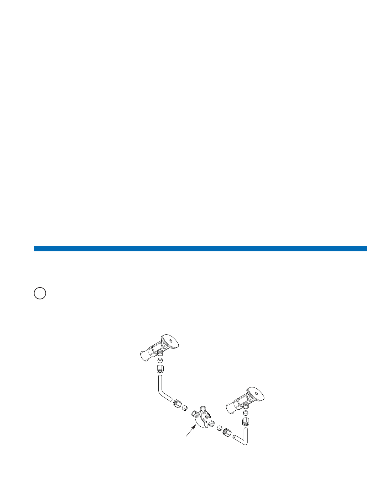
1
Install Mechanical Mixing Valve
A
If there is no tempered water supply, install Mechanical Mixing Valve between hot and cold water supply.
MIX-60-A
MECHANICAL MIXING VALVE
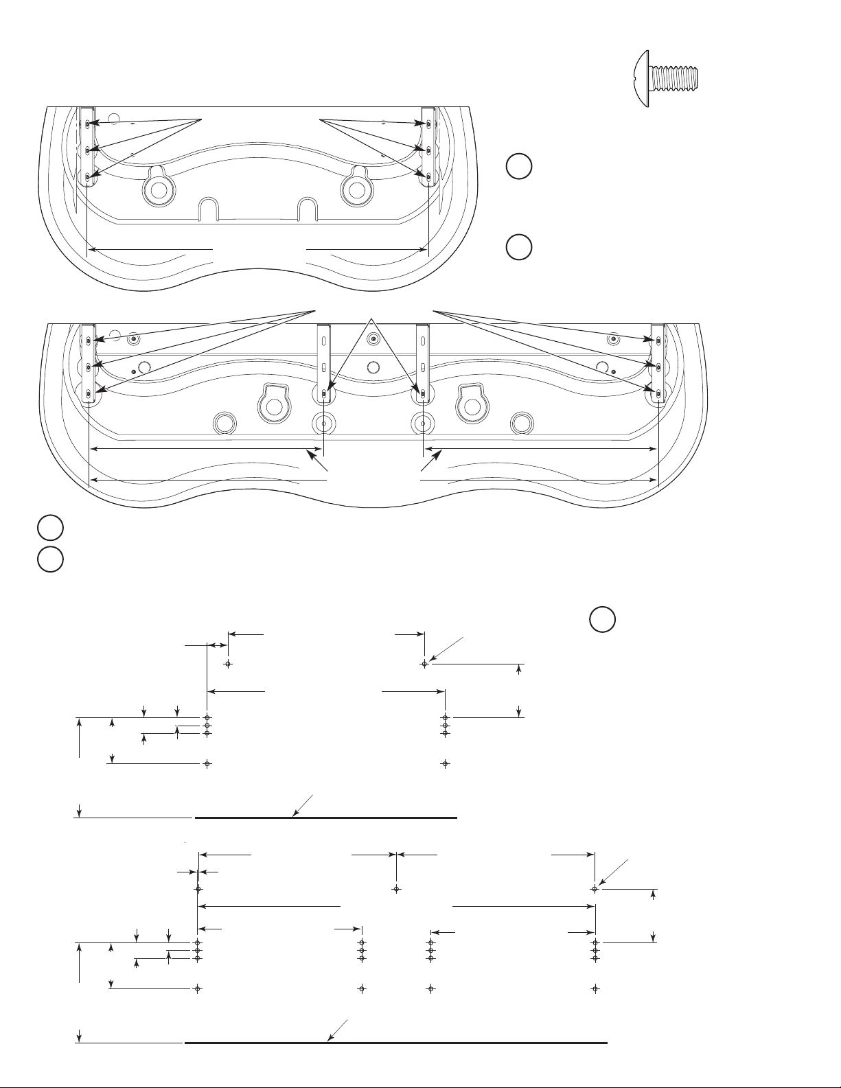
4
2
Mount Brackets and Basin to Wall
1/4”-20 x 1/2” Truss Head Screw
(Actual Size)
D
Mount Basin and Brackets to wall using fasteners with washers that hold over 1000 lbf (pounds-force) withdrawal load each.
Note: If desired, detach Brackets from Basin and mount Brackets to wall first. Then mount Basin to Brackets using 1/4”-20 x 1/2” Truss Head Screws.
Grid Strainer may be installed prior to attaching Basin to Brackets. Refer to Step 3.
E
Level Brackets in all
directions before tightening
fasteners securely. If desired,
apply caulk between Basin
and Wall.
Note: If installation is on soft wall
place 1/16” thick stainless or
galvanized steel sheets between the
Wall and the Brackets. These sheets
must be larger in area than the
mounting surfaces of the Brackets,
and must have thru-holes that align
with the Bracket’s mounting holes.
A
Attach Brackets to Basin using 1/4”-20 x 1/2”
Truss Head Screws. Double Station uses six
(6) Fasteners. Triple Station uses eight (8)
Fasteners.
B
Measure distance between brackets. Make
sure the carrier (when needed) can
accommodate the proper location for the
brackets.
C
Determine the appropriate location for the holes to secure the brackets to the wall. Use the following dimensions as a reference.
DOUBLE STATION
DOUBLE STATION
TRIPLE STATION
TRIPLE STATION
1/4”-20 x 1/2”
TRUSS HEAD SCREWS (6)
1/4”-20 x 1/2”
TRUSS HEAD SCREWS (8)
DISTANCE BETWEEN
BRACKETS
DISTANCE BETWEEN
BRACKETS
3-3/8” (86 mm)
APPROXIMATE LOCATION
2-1/2”
(64 mm)
7-1/2”
(191 mm)
“F”
SEE TABLE ON
PAGE 2
1-1/4”
(32 mm)
32” (813 mm)
APPROXIMATE LOCATION
DISTANCE BETWEEN
BRACKETS - STEP 2B
FINISHED FLOOR
HEAD SECURING
LOCATIONS (2)
8-3/4” (222 mm)
APPROXIMATE LOCATION
1/8” (3 mm)
APPROXIMATE LOCATION
2-1/2”
(64 mm)
7-1/2”
(191 mm)
“F”
SEE TABLE ON
PAGE 2
1-1/4”
(32 mm)
32” (813 mm)
APPROXIMATE LOCATION
DISTANCE BETWEEN
BRACKETS - STEP 2B
DISTANCE BETWEEN
BRACKETS - STEP 2B
FINISHED FLOOR
32-1/4” (819 mm)
APPROXIMATE LOCATION
DISTANCE BETWEEN
BRACKETS - STEP 2B
HEAD SECURING
LOCATIONS (3)
8-3/4” (222 mm)
APPROXIMATE LOCATION
 Loading...