

Page 1
PRIOR TO INSTALLATION
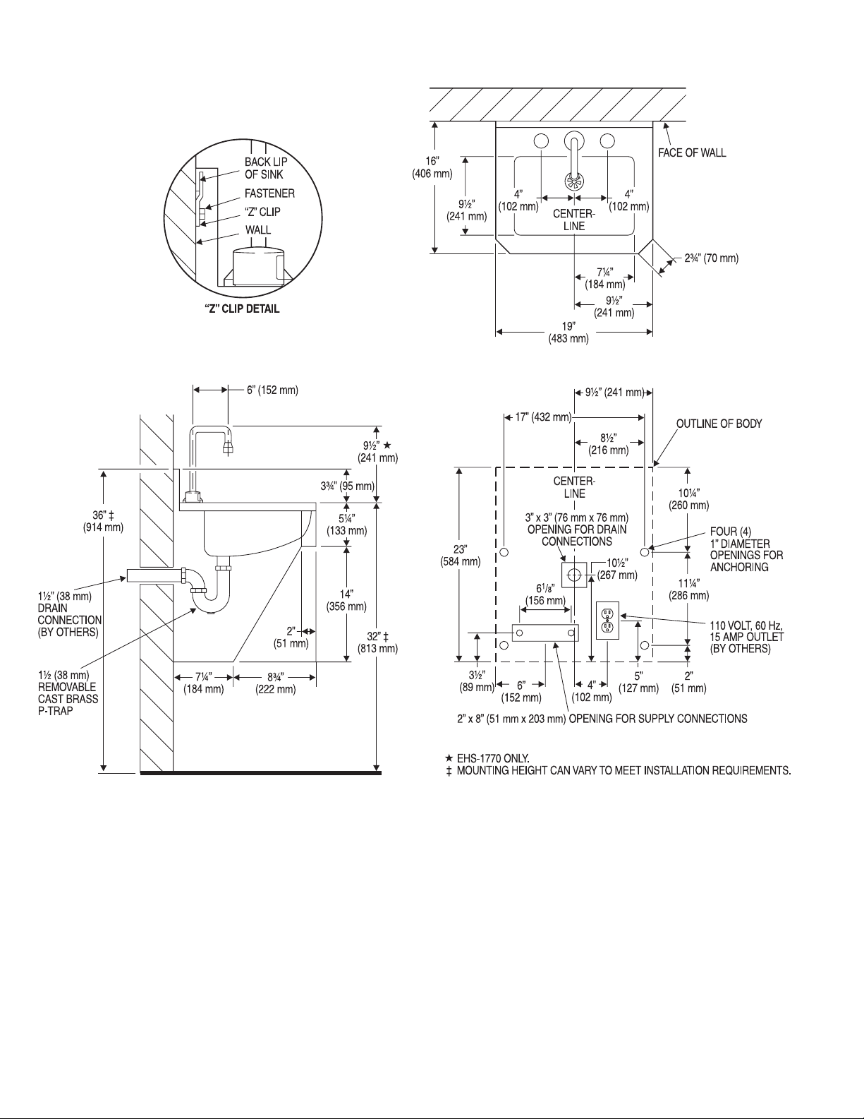
Before installing the EHS-1000 Series Hand Washing Sink, install the items
listed below. Also, refer to the rough-in diagrams on Page 2.
• Ground Fault Interrupt (GFCI) Electrical Receptacle for Plug-in Transformer
(one for each sink) — 120 VAC, 2 amp service for each
ETF-233 Plug-in Transformer (24 VAC, 35 VA)
• Drain line
• Hot and cold water supply lines or tempered water supply line
Important:
• ADEQUATE STRUCTURAL SUPPORT IN OR BEHIND THE WALL IS
REQUIRED. STRUCTURAL SUPPORT MUST WITHSTAND WEIGHT OF SINK
WHEN FILLED WITH WATER.
• INSTALL ALL ELECTRICAL WIRING IN ACCORDANCE WITH APPLICABLE
CODES AND REGULATIONS.
• INSTALL ALL PLUMBING IN ACCORDANCE WITH APPLICABLE CODES AND
REGULATIONS.
• A 24 VAC STEP-DOWN TRANSFORMER (SUPPLIED) MUST BE USED.
• USE APPROPRIATE PRECAUTIONS WHILE CONNECTING TRANSFORMER
TO 120 VAC POWER SOURCE.
• DO NOT PLUG TRANSFORMER INTO POWER SOURCE (RECEPTACLE)
UNTIL ALL WIRING IS COMPLETED. ALLOWING 24 VAC TRANSFORMER
WIRES TO TOUCH OR SHORT WHILE POWER IS BEING SUPPLIED WILL
CAUSE PERMANENT DAMAGE TO THE TRANSFORMER AND CIRCUIT
CONTROL MODULE.
• KEEP THREAD SEALANT OUT OF YOUR WATERWAY TO PREVENT
COMPONENT PART DAMAGE! DO NOT USE ANY SEALANT ON
COMPRESSION FITTINGS. FOR THREADED PIPE FITTINGS, DO NOT APPLY
SEALANT TO THE FIRST TWO “STARTER” THREADS.
• FLUSH ALL WATER LINES PRIOR TO MAKING CONNECTIONS.
Protect the chrome or special finish of this Hand Washing Sink — DO NOT
use toothed tools to install or service it. Also, see "Care and Cleaning" section
of this manual.
TOOLS REQUIRED FOR INSTALLATION
• Electric drill for drilling anchor holes
• Standard socket set or open end wrench set for installing anchoring
fasteners, “Z” clip fasteners and connecting water lines
• Pipe wrench for installing drain line
ANCHORING HARDWARE
Anchoring hardware for securing the “Z” clip to the wall and the sink to the
wall is not supplied. The “Z” clip is supplied.
SINK LOCATION
Determine the appropriate location for the Hand Washing Sink. Consider that
hot and cold water supply lines, a drain line, and an electrical source
(receptacle) will be required. Compare the physical dimensions of the Sink to
the space available for installation. If wall is not load bearing, a carrier may
be required behind the wall.
Code No. 0816834
Rev. 0 (12/08)
INSTALLATION INSTRUCTIONS FOR
SENSOR ACTIVATED HAND WASHING SINK
LIMITED WARRANTY
Sloan Valve Company warrants its EHS-1000 Series Hand Washing Sinks to be made of first class materials, free from defects of material or workmanship under normal use
and to perform the service for which they are intended in a thoroughly reliable and efficient manner when properly installed and serviced, for a period of three years
(one year for special finishes) from date of purchase. During this period, Sloan Valve Company will, at its option, repair or replace any part or parts which prove to be thus
defective if returned to Sloan Valve Company, at customer’s cost, and this shall be the sole remedy available under this warranty. No claims will be allowed for labor,
transportation or other incidental costs. This warranty extends only to persons or organizations who purchase Sloan Valve Company’s products directly from Sloan Valve
Company for purpose of resale. This warranty does not cover the life of the batteries (battery operated models).
THERE ARE NO WARRANTIES WHICH EXTEND BEYOND THE DESCRIPTION ON THE FACE HEREOF. IN NO EVENT IS SLOAN VALVE COMPANY RESPONSIBLE FOR ANY
CONSEQUENTIAL DAMAGES OF ANY MEASURE WHATSOEVER.
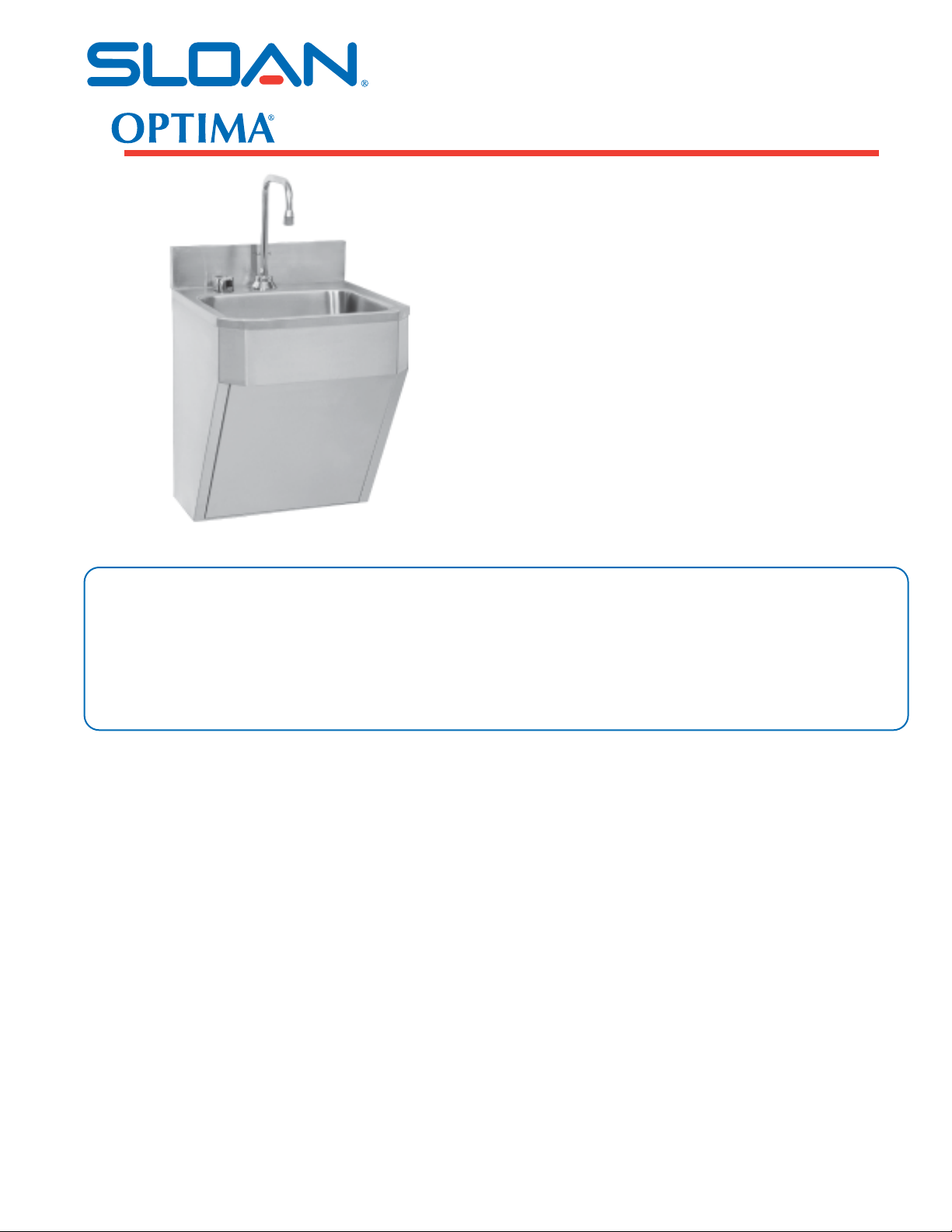
EHS-1080 Hand Washing Sink
with ETF-80 Faucet
EHS-1600 Hand Washing Sink
with ETF-600 Faucet
EHS-1660 Hand Washing Sink
with ETF-660 Faucet
EHS-1700 Hand Washing Sink
with ETF-700 Faucet
EHS-1750 Hand Washing Sink
with EBF-750 Faucet
†
EHS-1770 Hand Washing Sink
with ETF-770 Faucet
†
The EBF-750 Faucet is battery operated.
Model EHS-1770
EHS-1000 SERIES
Page 2
2
SINK ROUGH-IN
Page 3
3
1
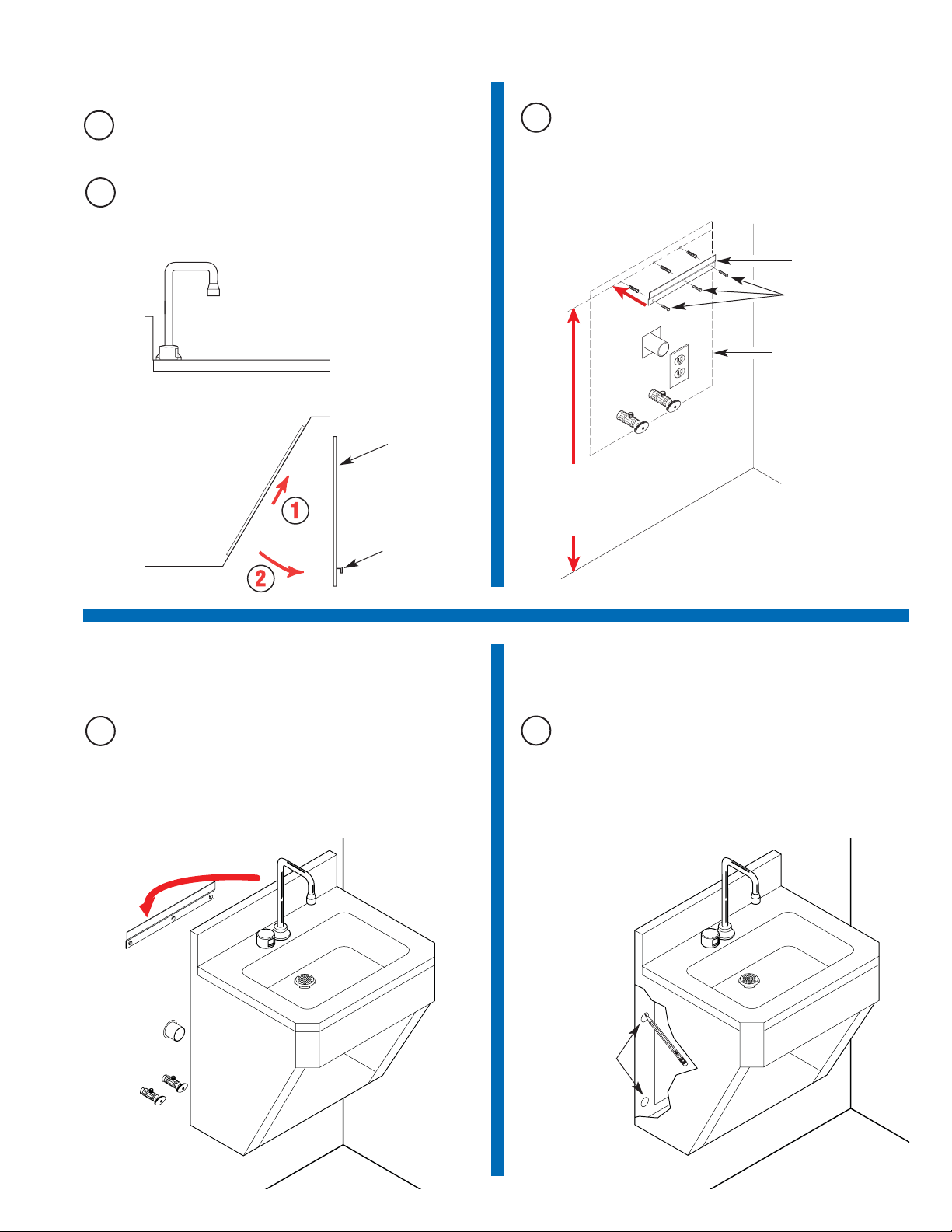
Unpack Scrub Sink and Remove
Access Panel
Remove Access Panel from Sink by lifting up on handle and
pulling outward. Do not use excessive force. The Access Panel is
not attached to the Sink with any fasteners.
B
4
Mark Mounting Hole Locations
on Wall
2
Install “Z” Clip to Wall
Install “Z” clip so that mounting holes measure 34-3/4” (883
mm) from floor surface for a standard 32” (813 mm) sink height.
NOTE: Mounting height can vary to meet individual installation
requirements. Adjust all rough-in and mounting dimensions
accordingly.
A
3
Install Sink on Wall
A
With the help of an assistant, carefully lift and hang the Sink onto
the “Z” clip. Position Sink as required.
A
Mark all four (4) Anchoring Hole locations using Sink as a
template. There are two holes on each side of the Sink.
STANDARD HEIGHT:
34-3/4” (883 mm)
FROM FLOOR TO
CENTER OF
FASTENER HOLES
OUTLINE OF
SINK
“Z” CLIP (SUPPLIED)
ANCHORING FASTENERS
(SUPPLIED BY OTHERS)
Carefully remove Sink from its protective carton. Examine the
carton for additional parts before discarding packaging material.
A
ACCESS
PANEL
HANDLE
USING SINK AS A
TEMPLATE, MARK
MOUNTING HOLES
ON WALL (2 HOLES
ON EACH SIDE OF
SINK)
Page 4
4
6
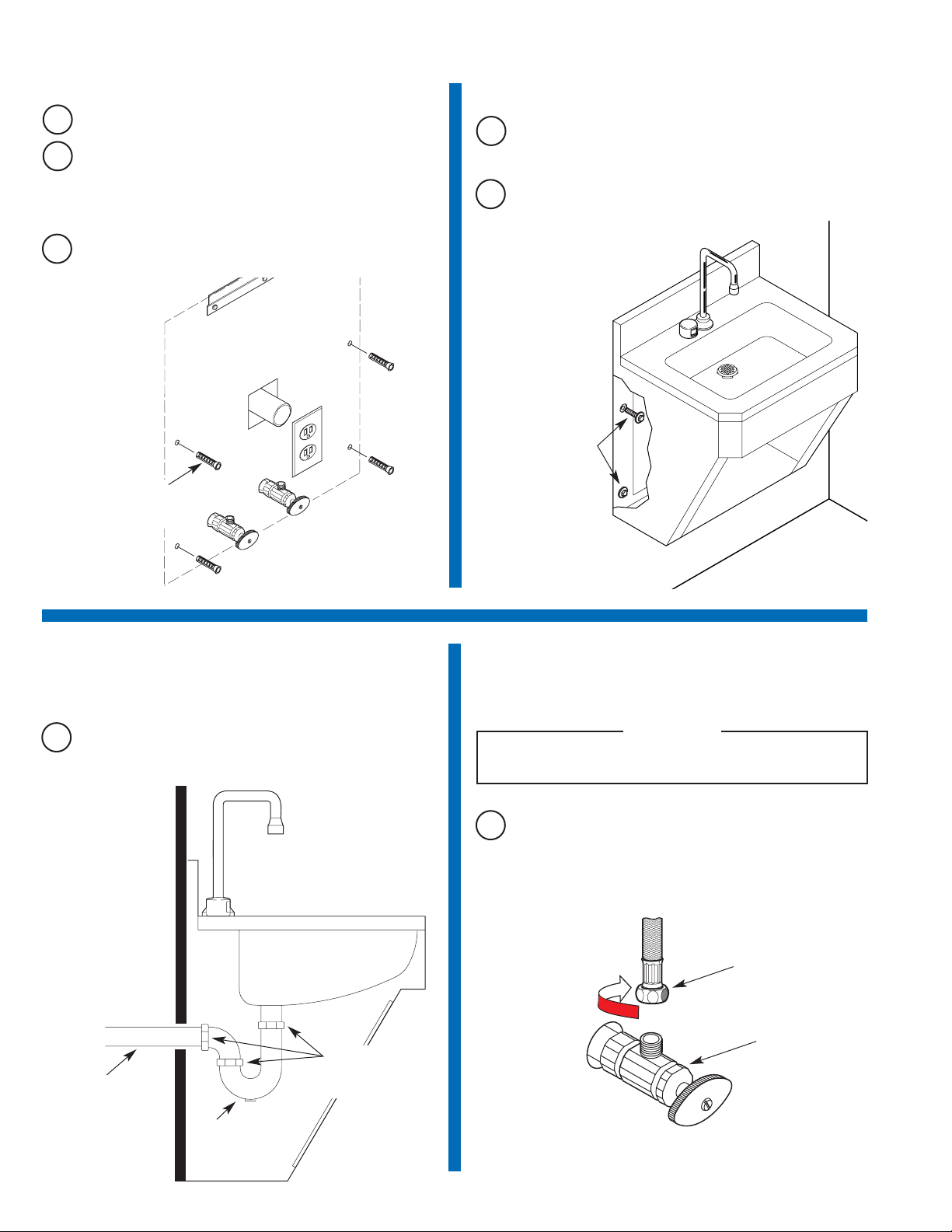
Mount Sink to Wall
7
Connect Sink Drain to Building
Drain
8
Connect Water Supply Lines
A
With the help of an assistant, carefully lift and re-hang the Sink
onto the “Z” clip. Position Sink so that the four (4) mounting holes
are aligned with the wall anchors.
B
Install and securely tighten the four (4) Anchoring Fasteners.
A
Connect the sink’s Drain Line to the building drain. Make sure that
all connections are secure to prevent leaking.
Before connecting water supply lines to Supply Stops, flush all
water lines until water runs clear.
IMPORTANT
A
Connect hot and cold water supply lines to Supply Stops.
(Supply Stops have a 1/2” male pipe thread inlet.)
A
Carefully remove Sink from the wall and place in a safe location.
5
Install Anchoring Hardware
B
Bore a 1” (25 mm) diameter hole into the wall at each of the four
(4) Anchoring Hole locations marked.
NOTE: Mounting height can vary to meet individual installation
requirements. Adjust all rough-in and mounting dimensions
accordingly.
C
Install the four (4) Anchors for sink as instructed in the Anchor
Manufacturer’s Installation Instructions.
INSTALL ANCHORS
(4 REQUIRED)
(SUPPLIED BY OTHERS)
INSTALL SINK
ANCHORING FASTENERS
(2 FASTENERS ON EACH
SIDE OF SINK)
(SUPPLIED BY OTHERS)
BUILDING’S DRAIN
SINK’S DRAIN
MAKE SURE THAT
ALL CONNECTIONS
ARE SECURE
CONNECT HOT AND COLD
WATER SUPPLY LINES TO
SUPPLY STOPS
SUPPLY STOP
Page 5
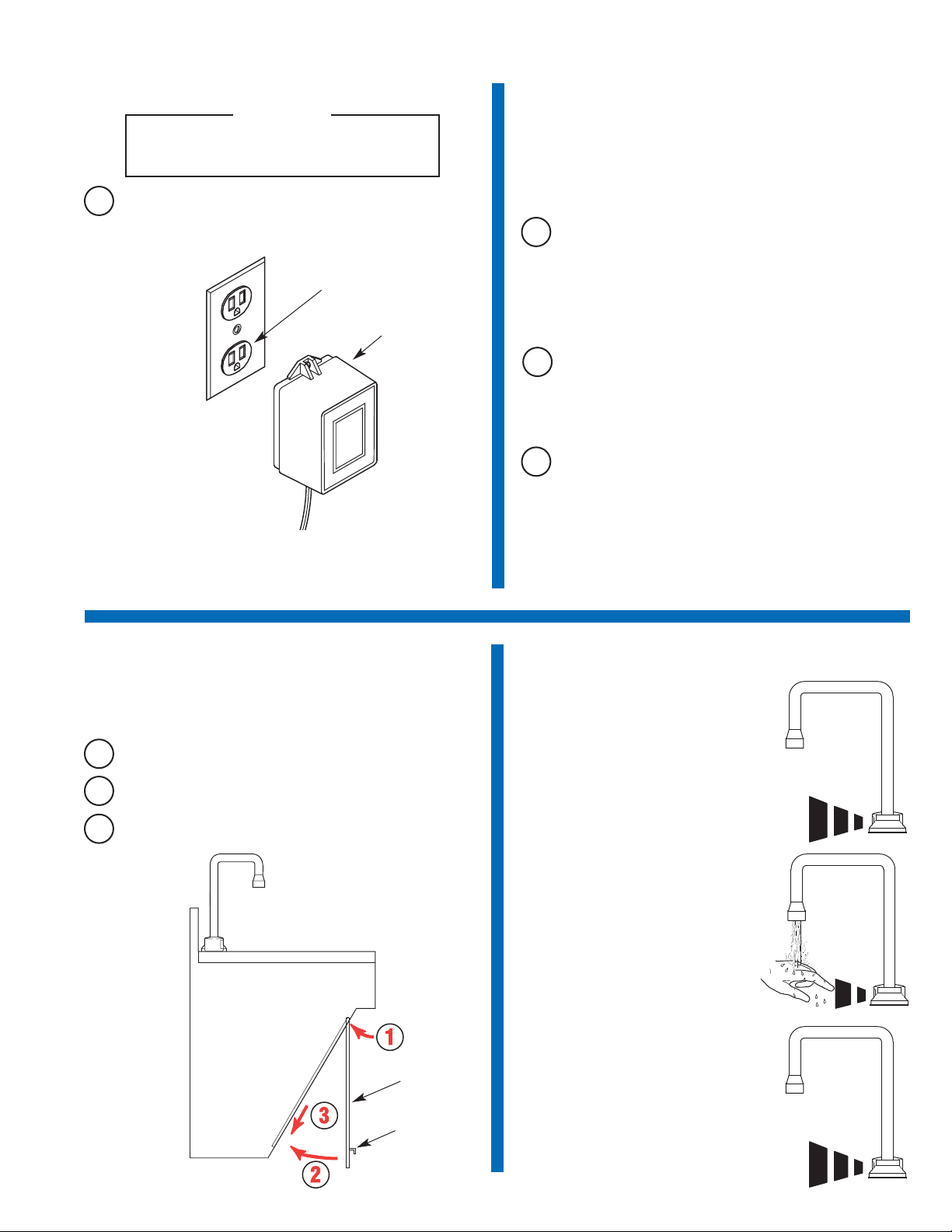
5
9
Plug Transformer into Receptacle
A
Make sure that power is supplied to the receptacle. Plug the
Transformer into the lower receptacle.
Plug-in Transformer MUST be used with a
Ground Fault Interrupt (GFCI) Receptacle to help
prevent possible electrical shock.
IMPORTANT
A
Remove Aerator or Spray Head from faucet spout. Open Supply
Stops. Activate Faucet for thirty (30) seconds by placing hand in
front of Sensor. The Solenoid Valve should “click” and water
should flow from the Spout. If this does not occur, refer to the
Troubleshooting section of this Installation Instructions.
B
Close Supply Stops. Install Aerator or Spray Head in Spout and
tighten securely. Reopen Supply Stops. Activate Faucet and check
for leaks.
C
If the Control Module Cover was removed, reinstall using the
Screws supplied.
Note: The Control Module is equipped with two LED lights. When power is
supplied by the Transformer, one LED will illuminate green. When Sensor is
activated, this LED will change to red. A second red LED illuminates when
Solenoid Valve is activated.
10
Start-Up
11
Reinstall Access Panel
A
Slide Access Panel up into top slot of Sink frame.
B
Swing Panel inward until flush with Sink frame.
C
Lower Panel into bottom slot of Sink Frame.
NOTE: Do NOT use excessive force to install Access Panel.
Faucet Operation
1. A continuous invisible beam of infrared
light is emitted from the OPTIMA
sensor.
2. As the user’s hands enter the beam’s
effective range, the beam is reflected
back into the sensor receiver and
activates the solenoid valve allowing
tempered water to flow from the faucet
into the sink. Water will flow until the
hands are removed or until the faucet
reaches its automatic time out limit
setting.
3. When hands are moved away from the
OPTIMA sensor, the loss of reflected
light initiates an electrical signal that
deactivates the solenoid valve,
shutting off the water flow. The circuit
then automatically resets and is ready
for the next user.
110 VOLT, 60 Hz, 15 AMP,
GFCI PROTECTED
ELECTRICAL OUTLET
ETF-233 PLUG-IN
TRANSFORMER
ACCESS
PANEL
HANDLE
ETF-770 Faucet Shown
Page 6
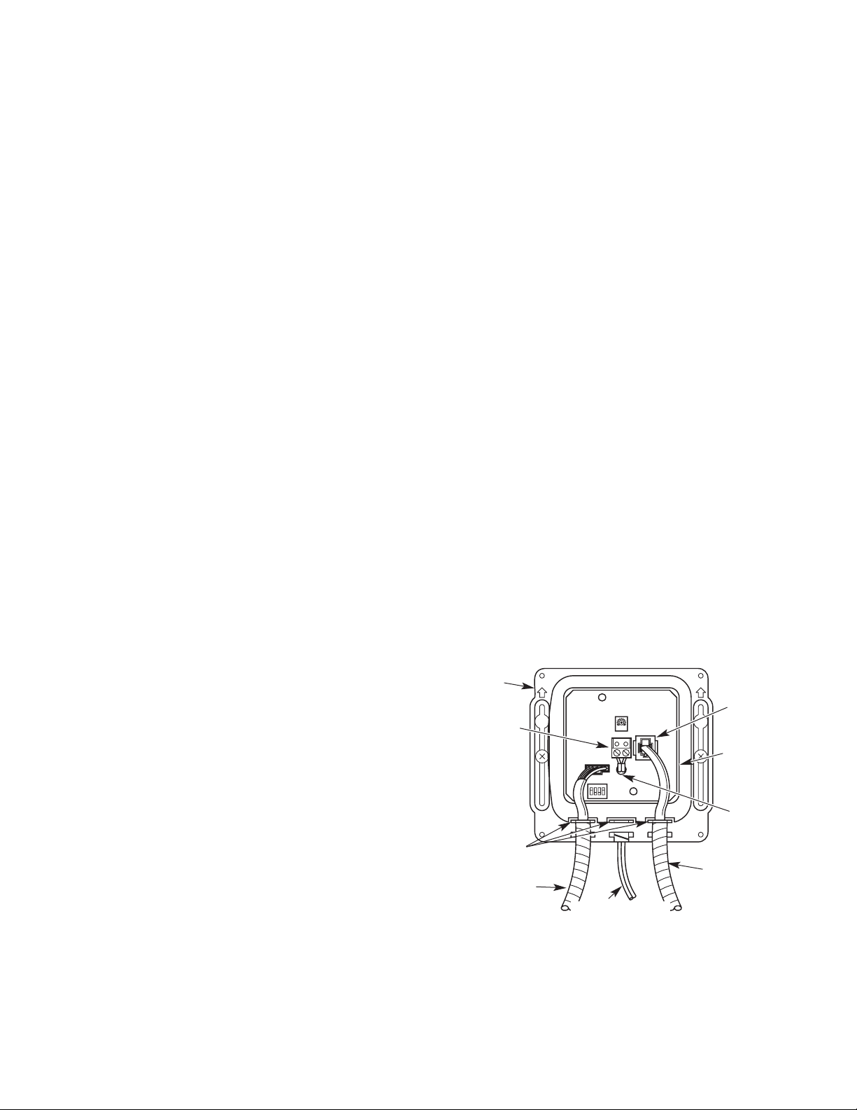
6
TROUBLESHOOTING GUIDE
For Models:
EHS-1080 Hand Washing Sink with ETF-80 Faucet
EHS-1600 Hand Washing Sink with ETF-600 Faucet
EHS-1660 Hand Washing Sink with ETF-660 Faucet
EHS-1700 Hand Washing Sink with ETF-700 Faucet
EHS-1770 Hand Washing Sink with ETF-770 Faucet
Note: Remove Cover from Control Module to check diagnostic lights.
1. PROBLEM:No water is delivered when Faucet is activated.
INDICATOR: If no LED lights illuminate:
CAUSE: No electricity is being supplied to Faucet.
SOLUTION: Ensure that the main power is turned “ON.” Check all
Transformer, Sensor, Solenoid and Cable Connections. Make
sure that Transformer is supplying 24 VAC (Volts AC). If no
voltage is detected, replace Transformer.
CAUSE: There is an electrical system malfunction.
SOLUTION: Reset electrical system. Unplug Sensor Connection. Disconnect
power to circuit for ten (10) seconds. Reconnect.
INDICATOR: If the GREEN LED does NOT illuminate when power is
reconnected:
CAUSE: There is an electrical system malfunction.
SOLUTION: Reset electrical system. Unplug Sensor Connection. Disconnect
power to circuit for ten (10) seconds. Reconnect.
CAUSE: The Control Module circuit is “dead.”
SOLUTION: Replace ETF-450-A Control Module.
INDICATOR: If GREEN LED illuminates AND changes to RED when
hands are in the Sensor’s detection zone AND the RED Solenoid
LED illuminates:
CAUSE: Water supply stop(s) may be partially closed.
SOLUTION: Open supply stop(s) completely.
CAUSE: Debris is clogging Solenoid Filter.
SOLUTION: Shut off water supply. Remove, clean and reinstall Solenoid
Filter.
INDICATOR: If GREEN LED illuminates AND changes to RED when
hands are placed in the Sensor’s detection zone AND the RED
Solenoid LED flickers with a vibrating/clicking noise heard inside
the module:
CAUSE: There is a direct short in the Solenoid or Solenoid Cable.
SOLUTION: Replace with ETF-370-A Solenoid.
INDICATOR: If GREEN/RED LED illuminates AND changes to RED
when hands are NOT located in the Sensor’s detection zone BUT
the RED Solenoid LED (in upper left corner of circuit) does NOT
illuminate:
CAUSE: Sensor range is set too long and is detecting the sink.
SOLUTION: Reduce Sensor detection range.
CAUSE: Sensor is faulty.
SOLUTION: Replace Sensor.
INDICATOR: If GREEN LED illuminates BUT does NOT change to RED
when hands are placed in the Sensor’s detection zone:
CAUSE: Sensor range is set too short.
SOLUTION: Increase Sensor detection range.
CAUSE: Sensor is faulty.
SOLUTION: Replace Sensor.
2. PROBLEM:Sensing Range is too short.
CAUSE: Extended Range Sensitivity is required.
SOLUTION: Dip Switch number 4 should be in the “DOWN” (Extended
Range Sensitivity) position. Increase range by adjusting Range
Potentiometer clockwise (yellow phillips screw in blue base).
CAUSE: Faucet has Surgical Bend Gooseneck Spout.
SOLUTION: For Long Range use (recommended for Surgical Bend
Gooseneck Spout Faucet models), remove Range Jumper from
upper right hand corner of Circuit Board. Adjust Range
Potentiometer.
3. PROBLEM:Faucet activates by itself (false triggers).
CAUSE: Sensor range is set too long.
SOLUTION: Decrease range by adjusting Range Potentiometer
counterclockwise. If necessary, flip Dip Switch number 4 to the
“UP” (Reduced Range Sensitivity) position. Check surroundings
for factors that contribute to Sensor range detection problems
(bright lights, highly reflective surfaces, sunlight, etc.).
4. PROBLEM:Faucet delivers very low flow or just a dribble.
CAUSE: Water supply stop(s) may be partially closed.
SOLUTION: Open supply stop(s) completely.
CAUSE: Debris is clogging Solenoid Filter.
SOLUTION: Shut off water. Remove, clean, and reinstall Solenoid Filter.
CAUSE: Solenoid is worn or faulty.
SOLUTION: Rebuild with ETF-1009-A Solenoid Repair Kit or replace ETF-
370-A Solenoid.
CAUSE: Debris is clogging Faucet Aerator or Spray Head.
SOLUTION: Shut off water. Remove Aerator or Spray Head (use Key if
required). Clean and reinstall Aerator or Spray Head.
5. PROBLEM:Faucet does not stop delivering water or continues to drip
after user is no longer detected (even after power to the Module has
been disconnected).
CAUSE: Solenoid Valve is installed backward.
SOLUTION: Disconnect Solenoid. Reconnect Solenoid with water flow
toward the Faucet (see arrow on Solenoid).
CAUSE: Debris is clogging Solenoid.
SOLUTION: Remove and clean Solenoid Operator. If necessary, rebuild with
ETF-1009-A Repair Kit.
CAUSE: Seat in Solenoid Valve body is damaged or pitted.
SOLUTION: Replace with ETF-370-A Solenoid.
CONTROL
MODULE
ENCLOSURE
FROM SOLENOID
VALVE
FROM TRANSFORMER
STRAIN RELIEF SLOTS
FROM FAUCET SPOUT
TERMINAL BLOCK
CONNECTOR
BOARD
POWER
CABLE
MODULAR
RECEPTACLE
When assistance is required, please contact Sloan Valve Company
Installation Engineering Department at:
1-888-SLOAN-14 (1-888-756-2614) OR 1-847-233-2016
Page 7
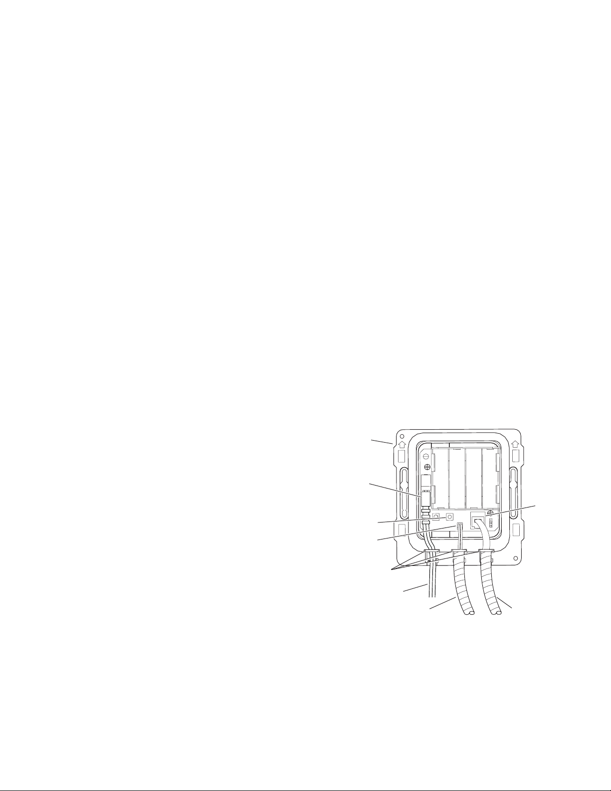
Note: Remove Cover from Control Module to check diagnostic lights.
1. PROBLEM: Sensor LED does not function (indicator light on sensor
window in faucet spout does not flash during initial 10
minute set-up mode).
CAUSE: There is no visible indicator light. Normal operation.
SOLUTION: This is a normal operating feature of the faucet.
2. PROBLEM: Faucet does not deliver any water when Sensor is
activated.
INDICATOR: Solenoid valve produces audible “CLICK.”
CAUSE: Water supply stop(s) closed.
SOLUTION: Open supply stop(s) completely.
INDICATOR: Solenoid valve DOES NOT produce an audible “CLICK.”
CAUSE: Solenoid Lead is not properly connected to the Control Module.
SOLUTION: Disconnect and reconnect Solenoid Lead to Control Module.
CAUSE: No battery or Transformer power is being supplied to Sensor.
SOLUTION: Ensure that the batteries are installed properly. Check that the
orientation of each battery matches the positive (+) and
negative (—) symbols shown at bottom of battery
compartment. Reinsert Batteries into Control Module.
Transformer (optional) is unplugged or wall receptacle has no
power.
CAUSE: Sensor Cable is not properly connected to the Control Module.
SOLUTION: Disconnect and reconnect Sensor Cable to Control Module.
CAUSE: Sensor range is set at minimum distance.
SOLUTION: Increase Sensor range.
CAUSE: Control Module assembly is defective.
SOLUTION: Replace Control Module assembly.
3. PROBLEM: Faucet delivers only a slow flow or dribble when Sensor
is activated.
CAUSE: Water supply stop(s) partially closed.
SOLUTION: Open supply stop(s) completely.
CAUSE: Solenoid Filter is clogged.
SOLUTION: Remove, clean and reinstall Filter.
CAUSE: Aerator or Spray Head is clogged.
SOLUTION: Remove, clean and reinstall Aerator or Spray Head.
4. PROBLEM: Faucet does not stop delivering water or continues to
drip after user is no longer detected (automatic shut-off
fails even when batteries are removed).
CAUSE: Solenoid Valve has been connected backwards.
SOLUTION: Disconnect Solenoid Valve compression fittings at both the inlet
and outlet positions. The water should flow from inlet through
the Solenoid Valve to the outlet according to the direction of the
arrow shown on the side of the Solenoid Valve. Reconnect the
compression fittings in the correct orientation.
CAUSE: Solenoid Valve is dirty.
SOLUTION: Backflush by reversing water flow (opposite to the direction
shown by the arrow on the side of the Solenoid Valve) through
the Solenoid Valve. Reconnect the compression fittings in the
correct orientation. Activate faucet.
CAUSE: Solenoid Valve Module is defective.
SOLUTION: Replace Solenoid Valve Module.
5. PROBLEM: The water temperature is too hot or too cold on a faucet
connected to hot and cold supply lines with Bak-Chek
®
Tee.
CAUSE: Supply stops are not adjusted properly.
SOLUTION: Adjust supply stops.
NOTE: For some systems, a Thermostatic Mixing Valve may be
required.
6. PROBLEM: Red LED turns on in the control module (below deck).
CAUSE: One (or more) of the batteries is “dead.”
SOLUTION: To ensure proper operation, insert four (4) new AA-size Alkaline
batteries. Check that the orientation of each battery matches the
positive (+) and negative (—) symbols shown on the bottom
of the battery compartment. Reinsert Batteries into the Control
Module.
NOTE: Upon start-up mode (1st ten minutes) the control module
circuitry tests the batteries and the Red LED turns on if the
battery voltage is low. No Red LED light indicates normal
battery voltage.
NOTE: If reset button is pressed (initiates start up mode/1st ten
minutes), the battery voltage is checked. If voltage is too low,
product is stopped from operating and Red LED will turn on. No
Red LED light indicates normal battery voltage.
7. PROBLEM: Green LED initially turns on in the control module
(below deck) during start up mode, then will not appear
again.
CAUSE: For the 1st ten minutes of operation (batteries inserted or reset
button pressed) the Green LED will turn on when there is a target
present ( hands in front of sensor). After ten minutes, the Green
LED will no longer turn on.
SOLUTION: This is a normal operating feature of the faucet.
7
TROUBLESHOOTING GUIDE
For Model:
EHS-1750 Hand Washing Sink with EBF-750 Faucet
CONTROL
MODULE
ENCLOSURE
FROM SOLENOID VALVE
FROM OPTIONAL
TRANSFORMER
STRAIN
RELIEF
SLOTS
FROM FAUCET SPOUT
RESET
BUTTON
MODULAR
RECEPTACLE
LOCKING
CONNECTOR
POWER
CABLE
JACK
When assistance is required, please contact Sloan Valve Company
Installation Engineering Department at:
1-888-SLOAN-14 (1-888-756-2614) OR 1-847-233-2016
Page 8
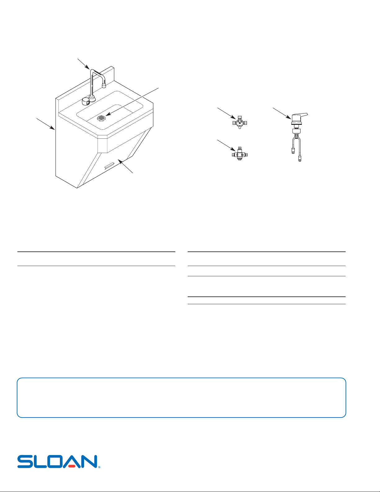
CARE AND CLEANING OF CHROME AND SPECIAL FINISHES
Do NOT use abrasive or chemical cleaners (including chlorine bleach) to clean the sink or faucet. Harsh cleaners may dull the luster and attack the
chrome or special decorative finishes. Use ONLY mild soap and water, then wipe dry with a clean cloth or towel.
While cleaning the sink area, protect the faucet from any splattering of cleaner. Acids and cleaning fluids will discolor or remove chrome plating.
PARTS LIST
SLOAN VALVE COMPANY • 10500 Seymour Avenue • Franklin Park, IL 60131
Phone: 1-800-982-5839 or 1-847-671-4300 • Fax: 1-800-447-8329 or 1-847-671-4380
www.sloanvalve.com
Printed 12-08
Copyright © 2008 SLOAN VALVE COMPANY
Item Part Description
No. No.
1 — Sink Cabinet
2 — Access Panel
3 — Lavatory or Gooseneck Faucet Assembly †
4 — Grid Strainer Assembly
— Drain/P-trap Assembly (not shown)
† Part number varies with faucet model, consult factory.
For additional information about Sloan Mixing Valves or Trim Plates, consult
our Installation Instructions and Maintenance Guides.
Item Part Description
No. No.
OPTIONAL MIXING VALVES
5 MIX-60-A Below Deck Mechanical Water Mixing Valve (BDM Variation)
6 MIX-135-A Below Deck Thermostatic Water Mixing Valve (BDT Variation)
7 MIX-110-AA Optimix
®
Deck Mounted Water Mixing Valve
SOLENOID VALVE REPAIR KIT
— ETF-1009-A Solenoid Repair Kit
If further assistance is required, please contact the Sloan Valve Company
Installation Engineering Department at:
1-888-SLOAN-14 (1-888-756-2614)
NOTICE: The information contained in this document is subject to change without notice.
1
2
3
4
5
6
7
 Loading...