

Slant/Fin VHG-100-CH, VHG-180-CH, VHG-80-CH, VHG-90-CO, VHG-150-CO Installation And Service Manual
...Page 1

Heating Contractor
Boiler Model Number
Address
Boiler Serial Number
Phone Number
Installation Date
INSTALLATION AND SERVICE MANUAL
- Do not store or use gasoline or
California Proposition 65 Warning: This product contains ch emicals known to the State
of California to cause cancer, birth defects, or other reproductive harm.
adjacent
for reference.
This manual must be
left with owner and
must be hung on or
to the boiler
RESIDENTIAL BOILER MODELS
VGH-80-CH / VGH-100-CH / VGH-120-CH /
VGH-150-CH / VGH-180-CH
VGH-90-CO / VGH-150-CO / VGH-200-CO
HIGH EFFICIENCY CONDENSING GAS BOILER
QUICK CONTENTS
FULL TABLE OF CONTENTS ................................ 3
1.0 SAFETY GUIDELINES .......................................... 8
2.0 INTRODUCTION. ................................................ 13
3.0 TECHNICAL DATA ........................................................ 16
4.0 BOILER DIMENSIONS .......................................... 26
5.0 ACCESSORIES AND UNPACKING ....................... 28
6.0 INSTALLATION LOCATION ................................... 29
7.0 CONNECTIONS ..................................................... 32
8.0 CIRCULATOR CHARACTERISTICS ...................... 47
9.0 FLUE GAS AND AIR SUPPLY SYSTEM ................ 52
10.0 ELECTRICAL INSTALLATION ............................... 76
11.0 USING THE DISPLAY ................................................ 88
12.0 TEMPERATURE PROTECTION......................... 113
13.0 ERROR INFORMATION ...................................... 113
14.0 CASCADING SYSTEM SETUP .......................... 119
15.0 SYSTEM TEST ................................................. 125
16.0 COMMISSIONING THE BOILER ........................ 126
17.0 ADJUSTING AND SETTING THE BOILER ......... 129
18.0 INSPECTION, MAINTENANCE AND SERVICE .. 136
29.0 USER INSTRUCTIONS ..................................... 148
20.0 INSTALLATION EXAMPLES .............................. 148
21.0 SPARE PARTS VGH -xx-CH ........................................ 152
22.0 SPARE PARTS VGH -xx-CO ........................................ 157
WARNING: If the information in
this manual is not followed
exactly, a fire or explosion may
result causing property damage,
personal injury or loss of life.
other flammable vapors and
liquids in the vicinity of this or
any other appliance.
- WHAT TO DO IF YOU SMELL GAS
•
Do not try to light any appliance.
•
Do not touch any electrical switch; do not use
any phone in your building.
•
Immediately call your gas supplier from a
neighbor’s phone. Follow the gas supplier’s
instructions.
•
If you cannot reach your gas supplier, call the
fire department.
- Installation and service must be performed by a
qualified installer, service agency or the gas
supplier.
Page 2

Page 3

TABLE OF CONTENTS
1 SAFETY GUIDELINES ................................................................................................................................ 8
2 INTRODUCTION ........................................................................................................................................ 13
TERMS AND ABBREVIATIONS ............................................................................................................. 13
CODES, STANDARDS AND REGULATIONS ............................................................................................ 14
MAINTENANCE AND INSPECTION ........................................................................................................ 14
FOR INSTALLATIONS IN THE COMMONWEALTH OF MASSACHUSETTS .................................................... 15
3 TECHNICAL DATA VGH RESIDENTIAL BOILERS ................................................................................. 16
Functional introduction ....................................................................................................... 16
LOCATION OF VERSION NUMBERS ...................................................................................................... 17
TECHNICAL SPECIFICATIONS DATASHE ETS ......................................................................................... 18
Technical specificat ions V G H-80-CH / VGH-90-CO / VGH-100-CH ................................. 18
Technical specifications VGH-120-CH / VGH-150-CO / VGH-150-CH ............................. 20
Technical specifications VGH-180-CH / VGH-200-CO ...................................................... 22
HIGH ALTITUDE OPERATION ............................................................................................................... 24
DHW SPECIFICATIONS VGH-CO SERIES ........................................................................................... 24
HEAT EXCHANGER INFORMATION....................................................................................................... 24
SPECIFICATIONS INPUT, OUTPUT, EFFICIENCY (AHRI) ........................................................................ 25
4 BOILER DIMENSIONS .............................................................................................................................. 26
VGH-80-CH / VGH-100-CH / VGH-120-CH / VGH-150-CH / VGH-180-CH ................................... 26
VGH-90-CO / VGH-150-CO / VGH-200-CO ................................................................................... 27
5 ACCESSORIES AND UNPACKING.......................................................................................................... 28
OPTIONAL ACCESSORIES .................................................................................................................. 28
SUPPLIED WITH THE BOILER .............................................................................................................. 28
6 INSTALLATION LOCATION OF THE VGH .............................................................................................. 29
GENERAL ......................................................................................................................................... 29
BOILER INSTALLATION LOCATION REQUIREMENTS .............................................................................. 29
INSTALLATION CLEARANCES ............................................................................................................. 30
MOUNTING THE BOILER ..................................................................................................................... 31
7 CONNECTIONS ......................................................................................................................................... 32
BOILER CONNECTIONS VGH-CH TYPES ............................................................................................ 32
BOILER CONNECTIONS VGH-CO TYPES ............................................................................................ 32
GAS PIPE CONNE CTION ..................................................................................................................... 33
Gas line connection ........................................................................................................... 33
CONDENSATE DRAIN CONNECTION .................................................................................................... 35
FLOW AND RETURN CONNECTIONS .................................................................................................... 35
EXPANSION VESSEL .......................................................................................................................... 36
PRESSURE RELIEF VALVE.................................................................................................................. 36
PRIMARY/SECONDARY PIPING .......................................................................................................... 36
CIRCULATOR FUNCTIONALITY ............................................................................................................ 37
FROST PROTECTION ......................................................................................................................... 38
INSTALLING A STRAINER AND/OR DIRT SEPARATOR ............................................................................. 38
SCALDING DANGER PROTECTION ....................................................................................................... 39
SUPPLY AND RETURN CONNECTIONS AND PRESSURE RELIEF VALVE. ................................................... 39
TEMPERATURE LIMITING DEVICE (DHW) ............................................................................................ 39
DRAIN VALVES (DHW) ...................................................................................................................... 39
SHUTOFF VALVES (DHW) ................................................................................................................. 39
CENTRAL HEATING WATER QUALITY .................................................................................................. 40
DOMESTIC WATER QUALITY ............................................................................................................. 41
USE OF GLYCOL ............................................................................................................................... 41
CHEMICAL WATER TREATMENT .......................................................................................................... 41
PLASTIC PIPING IN THE HEATING SYSTEM.......................................................................................... 42
UNDERFLOOR HEATING..................................................................................................................... 42
FLUSH THE SYSTEM WI TH FRESH WATER ............................................................................................ 43
AUTOMATIC AIR PURGING.................................................................................................................. 43
MANUAL DE-AIRING THE HEAT EXCHANGER ........................................................................................ 44
AUTOMATIC FEED VALVE .................................................................................................................. 44
WATER PRESSURE ........................................................................................................................... 44
E93.1901EN032 Installation and Service Manual SlantFin VGH-CH / CO 3
Page 4

INSTALLATION EXAMPLES .................................................................................................................. 45
Examples of a normal single boiler heating circuit with low loss header (preferable) ....... 45
Example of a multiple boiler heating circuit with low loss header ...................................... 46
8 CIRCULATOR CHARACTERISTICS ........................................................................................................ 47
PRESSURE DROP AND FLOW GRAPHS ................................................................................................ 47
Boiler resistance graph VGH-80-CH / VGH-90-CO ........................................................... 47
Boiler resistance graph VGH-100-CH ................................................................................ 47
Boiler resistance graph VGH-120-CH / VGH-150-CO ....................................................... 48
Boiler resistance VGH-150-CH .......................................................................................... 48
Boiler resistance graph VGH-180-CH / VGH-200-CO ....................................................... 49
Graph showing the Available Circulation pump head ........................................................ 49
MINIMUM REQUIRED CIRCULATOR HEAD. ............................................................................................ 50
MODULATING CIRCULATOR FOR CH DEMAND ...................................................................................... 50
MODULATING CIRCULATOR MODES .................................................................................................... 50
CIRCULATORS: MAXIMUM ELECTRICAL POWER ................................................................................... 51
Circulator power cord positioning ...................................................................................... 51
9 FLUE GAS AND AIR SUPPLY SYSTEM .................................................................................................. 52
GENERAL VENTING ........................................................................................................................... 52
Vent sizing ......................................................................................................................... 52
Vent and air inlet resistance table ...................................................................................... 53
VENT AND AIR INTAKE PIPE MATERIAL ................................................................................................ 53
Approved manufacturers.................................................................................................... 54
PVC / CPVC ................................................................................................................................... 54
Instructions for working with cementing PVC/ CPVC pipe connections ............................ 55
POLYPROPYLENE ............................................................................................................................. 55
REDUCER ........................................................................................................................................ 56
Flexible polypropylene ....................................................................................................... 56
STAINLESS STEEL VENT .................................................................................................................... 57
SEALED COMBUSTION AIR SUPPLY .................................................................................................... 57
Combustion air quality ....................................................................................................... 57
Air supply through humid areas ......................................................................................... 57
Air intake/vent connections ................................................................................................ 58
Air inlet pipe materials ........................................................................................................ 58
ROOM AIR ........................................................................................................................................ 59
Air contamination ............................................................................................................... 61
PROPER VENT INSTALLATION AND TYPE OF GAS VENT OR VENT CONNECTOR ........................................ 63
INSTALL VENT AND COMBUSTION AIR PIPING ....................................................................................... 63
REQUIREMENTS FOR INSTALLATION IN CANADA .................................................................................. 64
DIRECT VENTING OPTIONS ................................................................................................................ 64
WALL (HORIZONTAL) DIRECT VENTING ............................................................................................... 67
Vent/air termination - wall .................................................................................................. 67
Determine Location ............................................................................................................ 67
ROOF (VERTICAL) DIRECT VENTING ................................................................................................... 72
Vent/air termination – vertical ............................................................................................ 72
Determine location ............................................................................................................. 72
COMMON VENTING ........................................................................................................................... 75
EXISTING COMMON VENTING GUIDELINES ......................................................................................... 75
10 ELECTRICAL INSTALLATION ................................................................................................................. 76
GENERAL ......................................................................................................................................... 76
CONNECTION MAINS SUPPLY ............................................................................................................. 76
ELECTRICAL CONNECTIONS VGH-CH/CO BOILERS............................................................................ 76
Explanation of the low voltage connections VGH-CH boilers ............................................ 77
Explanation of the high voltage connections VGH-CH boiler s .......................................... 78
Explanation of the low voltage connections VGH-CO boil ers ............................................ 79
Explanation of the high voltage connections VGH-CO boi lers .......................................... 80
Ladder/Logic Diagram VGH-CH/CO BOILERS ................................................................. 81
Electrical schematic VGH-CH boilers ................................................................................ 82
Electrical schematic VGH-CO boilers ................................................................................ 84
SENSOR AVAILABILITY....................................................................................................................... 86
Sensor availability VGH-CH boilers ................................................................................... 86
Sensor availability VGH-CO boilers ................................................................................... 86
NTC SENSOR CURVE ........................................................................................................................ 86
4 E93.1901EN032 Installation and Service Manual SlantFin VGH-CH / CO
Page 5

PROGRAMMABLE IN- AND OUTPUTS ................................................................................................... 87
11 USING THE DISPLAY ............................................................................................................................... 88
DISPLAY AND BUTTONS ..................................................................................................................... 88
Display icons ...................................................................................................................... 89
SCREENS AND SETTINGS .................................................................................................................. 89
De-aeration Sequence ....................................................................................................... 89
CONTROL PANEL MENU STRUCTURE .................................................................................................. 90
Set Actual setpoint/DHW setpoint directly via the Status overview ................................... 91
Entering the menu .............................................................................................................. 91
Protected menu items ........................................................................................................ 92
Language settings .............................................................................................................. 92
BOILER HISTORY .............................................................................................................................. 93
ERROR LOGGING .............................................................................................................................. 93
SERVICE REMINDER .......................................................................................................................... 94
Service overdue logging .................................................................................................... 94
Reset the service reminder ................................................................................................ 94
GENERAL ......................................................................................................................................... 95
Circulator start exercise every 24 hours ............................................................................ 95
Frost protection .................................................................................................................. 95
Flue temperature protection ............................................................................................... 95
Appliance selection ............................................................................................................ 96
IGNITION CYCLE ............................................................................................................................... 96
Flame detection ................................................................................................................. 96
Flame recovery .................................................................................................................. 97
CONTROL FUNCTIONS CENTRAL HEATING .......................................................................................... 97
Room thermostat only; CH mode 0 (Default setting) ......................................................... 97
CH with an outdoor temperature reset and thermostat; CH mode 1 ................................. 98
CH with constant circulation system outdoor reset; CH mode 2 ..................................... 100
CH with constant circulation and permanent heat demand; CH mode 3 ......................... 101
Central Heating with analog input control of setpoint; CH mode 4 .................................. 101
CH with analog input control of power output; CH mode 5 .............................................. 102
CONTROL FUNCTIONS DOMESTIC HOT WATER ................................................................................ 103
No Domestic Hot Water; DHW mode 0 ........................................................................... 103
High pressure drop indirect tank DHW mode 1 and 2 (VGH-CH boilers only) ................ 103
DHW Storage with sensor; DHW mode 1 ........................................................................ 103
DHW Storage with thermostat; DHW mode 2.................................................................. 104
Instantaneous water heating with plate heat exchanger; DHW mode 5 .......................... 105
Anti-legionella protection.................................................................................................. 105
MENU STRUCTURE DISPLAY ............................................................................................................ 106
12 TEMPERATURE PRO TECTION ............................................................................................................. 113
13 ERROR INFORMATION .......................................................................................................................... 113
BOILER HISTORY ............................................................................................................................ 113
LOCKOUT CODES............................................................................................................................ 114
BLOCKING CODES .......................................................................................................................... 116
WARNINGS .................................................................................................................................... 118
14 CASCADING ............................................................................................................................................ 119
SYSTEM SETUP .............................................................................................................................. 119
BOILER CASCADE COMMUNICATION S ETUP ....................................................................................... 119
Setting the boiler address ................................................................................................ 120
E2prom address selection through e2prom setting ......................................................... 121
Cascade – Heating only (CH) Managing boiler ............................................................... 121
Cascade – Domestic Hot Water Settings ........................................................................ 121
Cascade – DHW priority .................................................................................................. 122
Cascade – Start/stop sequence ....................................................................................... 122
Cascade – Power balance mode ..................................................................................... 122
CASCADE – BOILER ROTATION ........................................................................................................ 122
Next depending to start selection .................................................................................... 123
CASCADE ERROR HANDLING .......................................................................................................... 123
Cascade Frost protection ................................................................................................. 123
Emergency mode ............................................................................................................. 124
Managing boiler error ....................................................................................................... 124
E93.1901EN032 Installation and Service Manual SlantFin VGH-CH / CO 5
Page 6

SYSTEM TEST......................................................................................................................................... 125
15
16 COMMISSIONING THE BOILER............................................................................................................. 126
FIRST: FLUSHING THE BOILER WITH WATER ...................................................................................... 126
SECOND: FILLING & VENTING THE BOILER AND THE SYSTEM .............................................................. 126
THIRD: CHECK THE WATER FLOW ..................................................................................................... 126
MOUNTING THE CONDENSATE TRAP ................................................................................................ 127
CHECKING GAS PRE SSU RE.............................................................................................................. 127
FIRING FOR THE FIRST TIME ............................................................................................................ 128
17 ADJUSTING AND SETTING THE BOILER ............................................................................................ 129
INTRODUCTION ............................................................................................................................... 129
Combustion table ............................................................................................................. 129
Setting screws gas valve: drawings ................................................................................. 130
CO
/ O2 ADJUSTMENT PROCEDURES.............................................................................................. 131
2
VENTURI ADJUSTEMENT .................................................................................................................. 131
CONVERSION FROM NATURAL GAS TO PROPANE ............................................................................... 132
START UP CHECKLIST .................................................................................................................... 134
18 INSPECTION, MAINTENANCE AND SERVICE ..................................................................................... 136
GENERAL ....................................................................................................................................... 136
SAFETY INSTRUCTIONS CRYSTALLINE SILICA ................................................................................... 136
INSPECTION, MAINTENANCE AND SERVICE TASKS ............................................................................. 138
REPLACING HEATEXCHANGER PARTS. ............................................................................................. 142
Replacement of the burner door gasket .......................................................................... 142
Fiber braid replacement ................................................................................................... 142
Replacement of the burner door insulation. ..................................................................... 143
Replacement of the Rear wall insulation disk .................................................................. 145
Replacement Ignition / ionization electrode ..................................................................... 145
CLEANING THE BRAZED PLATE HEAT EXCHANGER ........................................................................... 146
MAINTENANCE CHECKLIST .............................................................................................................. 147
19 USER INSTRUCTIONS ........................................................................................................................... 148
20 INSTALLATION EXAMPLES .................................................................................................................. 148
21 SPARE PARTS VGH-xx-CH ................................................................................................................... 152
SPARE PART LIST VGH-XX-CH ....................................................................................................... 154
22 SPARE PARTS VGH-CO ........................................................................................................................ 157
SPARE PART LIST VGH-XX-CO ....................................................................................................... 159
6 E93.1901EN032 Installation and Service Manual SlantFin VGH-CH / CO
Page 7

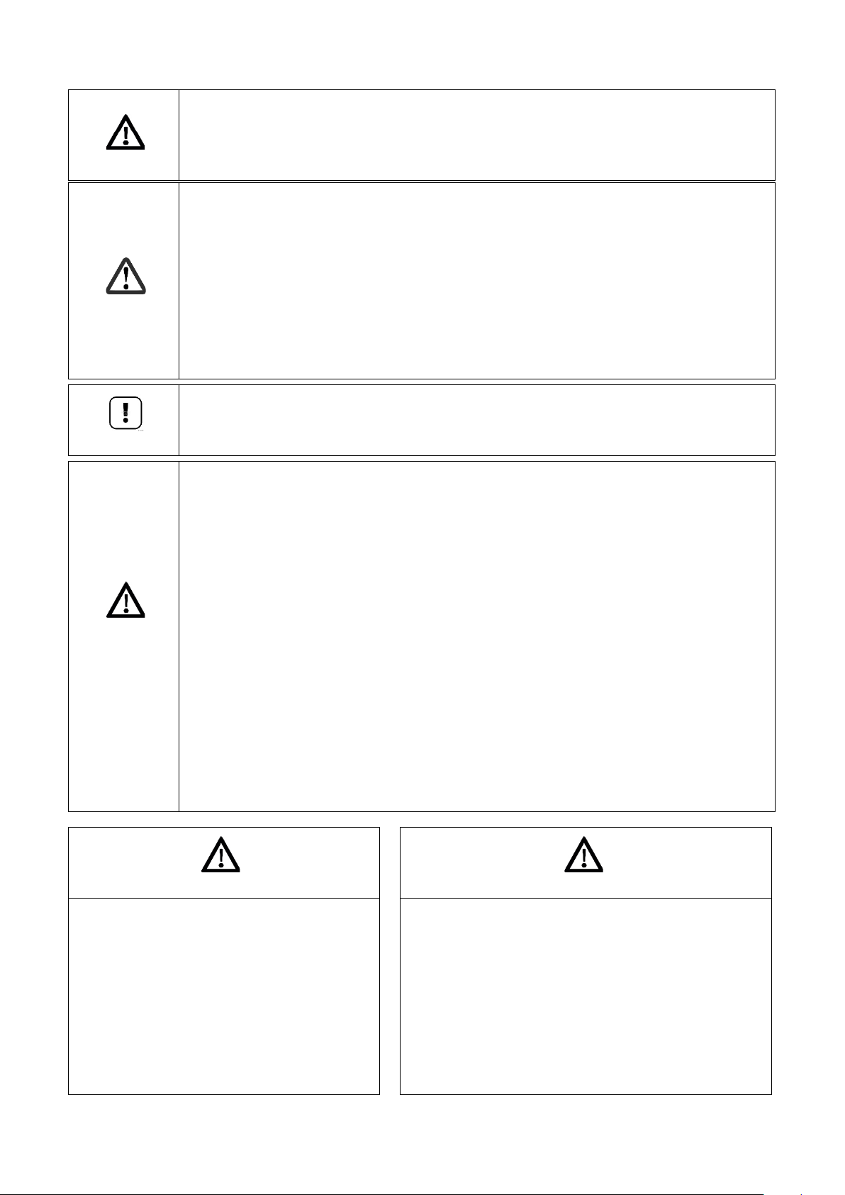
IMPORTANT
THE FOLLOWING WARNINGS AND STATEMENTS BEFORE READING
indicates the presence of an imminently hazardous situation that will cause
death, serious personal injury or substantial property damage.
indicates the presence of a hazardous situation which can cause death,
serious personal injury or substantial property damage.
indicates a hazardous situation which will or can
cause minor or moderate personal injury or property damage.
hazards due to electric shock.
indicates speci al instruc tions on i nstallatio n, oper ation or mai ntenance t hat ar e
important but not related to personal injury or property damage.
is void. Failure to properly install this unit may result in property damage, serious injury to
occupants, or possibly death.
DANGER
WARNING
CAUTION
CAUTION
NOTICE
WARNING
READ ALL OF
THE INSTALLATION INSTRUCTIONS
Danger Sign:
Warning Sign:
Caution Sign plus Safety Alert Symbol:
Caution Sign plus a lightning bolt indicates the risk of electric shock and the potential of
Notice Sign:
This Boiler must be installed by a licensed a n d t r ained H e at ing T echnician or the Warranty
E93.1901EN032 Installation and Service Manual SlantFin VGH-CH / CO 7
Page 8
1 SAFETY GUIDELINES
8 E93.1901EN032 Installation and Service Manual SlantFin VGH-CH / CO
Page 9

CONSIGNES DE SÉCURITÉ.
E93.1901EN032 Installation and Service Manual SlantFin VGH-CH / CO 9
Page 10
n the event of a blocked vent the boiler w ill
operation.
only be reset by
• Should overheating occur or the gas supply fail to shut off, do not turn off or disconnect the
Read this manual entirely before setting domestic hot water setpoint(s).
• WARNING: There are no u s er s erv ic eable par ts o n th i s boi ler. Warr anty does n ot c over
recommended personal protective equipment. Installation and service must be
appliance.
WARNING: Improper installation, adjustment,
humans)
AVERTISSEMENT: Une installation, un réglage, une
pouvant l'être).
CAUTION
DANGER
NOTICE
WARNING
Avertissement
WARNING
This boiler is equi pped with a pressure s witch. I
lockout. No attempt by the user/owner should be made to put the boiler back into
A qualified service technician must be notified of the issue. The boiler should
a qualified service technician after they have diagnosed and corrected the issued that caused
the safety lockout of the boiler.
electrical supply to the circ ulator. Instead, shut of f the gas s upply at a locat ion external t o
the appliance.
• Do not use this boiler if any part has been under water. Immediately call a qualified service
technician to inspect the boiler and to r eplac e any part of the c ontrol sy stem and any gas
control which has been under water.
• Scalding
Water temperatures over 125 ºF (5 2 ºC) c an c ause sev ere burns i nstant ly, or dea th fro m
scalds. Children, the disabled and the elderly are at the highest risk of being scalded.
Feel water before bathing or showering.
We highly recommend the ins tal lat ion of a c ar b on m on ox ide (CO ) de tec tor i n the boi ler r oo m
for all installations.
defects caused by at t emp ts to s erv ice t h is bo il er by s o meon e other than a qualif ie d ga s
service technician. These attempts could cause property damage, personal injury or loss
of life.
• WARNING: Crystalline Sil ica - Certain components in the combustion chamber may
contain this potential carcinogen. Improper installation, adjustment, alteration, service or
maintenance can cause property damage, serious injury (exposure to hazardous
materials) or death. Refer to Section 18.2
for information on handling instructi ons and
performed by a qualified installer, service agency or the gas supplier (who must read and
follow the supplied instructions be fore install ing, servic ing, or removin g this boiler. This
boiler contains materials that have been identified as carcinogenic, or possibly
carcinogenic, to humans).
• WARNING: There are no u s er ser v iceable par ts o n t h i s boi ler. Warranty does not c ov er
defects caused by at t emp ts to s erv ice t h is bo il er by s o meon e other than a qualif ie d ga s
service technician. These attempts could cause property damage, personal injury or loss
of life.
• a water heater that will be used t o supply p otable water s hall not be co nnected to a ny
heating system or component(s) previously used with a non-potable water heating
alteration, service or maintenance can cause
property damage, personal injury (exposure to
hazardous materials) * or loss of life.
Installation and service must be performed by
a qualified installer, service agency or the gas
supplier (who must read and follow the
supplied instructions before installing,
servicing, or removing this boiler. This boiler
contains materials that have been identified as
carcinogenic, or possibly carcinogenic, to
10 E93.1901EN032 Installation and Service Manual SlantFin VGH-CH / CO
modification, une réparation ou un entretien non
conforme aux normes peut entraîner des dommages
matériels, des blessures (exposition à des matières
dangereuses) ou la mort. L'installation et l'entretien
doivent être effectués par un installateur ou un service
d'entretien qualifié ou le fournisseur de gaz (qui doivent
avoir lu les instructions fournies avant de faire
l'installation, l'entretien ou l'enlèvement de la chaudière
et les respecter. Cette chaudière contient des matériaux
qui ont été identifiés comme étant cancérogènes ou
Page 11

Avertissement
L'installation et l'entretien doivent être assurés par un installateur ou un service
AVERTISSEMENT. Assurez-vous de bien suivre les instructions données dans
AVERTISSEMEN T. Assure z-vous de b ien suivre les ins tructions d onnées d ans cette notice p our rédu ire au
minimum le risque d'incendie ou d'explosion ou pour éviter tout dommage matériel, toute blessure ou la mort.
(pour installateurs francophones)
cette notice pour réduire au minimum le risque d'incendie ou d'explosion ou pour
éviter tout dommage matériel, toute blessure ou la mort.
— Ne pas entreposer ni utiliser d'essence ou ni d'autres vapeurs ou liquides
inflammables à proximité de cet appareil ou de tout autre appareil.
— QUE FAIRE SI VOUS SENTEZ UNE ODEUR DE GAZ :
•Ne pas tenter d’allumer d’appareils.
•Ne touchez à aucu n interrupteur. N e pas vous servir de s téléphones dans le bât iment
où vous vous trouvez.
•Appelez immédiatement votre fournisseur de gaz depuis un voisin. Suivez les
instructions du fournisseur.
•Si vous ne pouvez rejoindre le fournisseur de gaz, appelez le service des incendies.
d'entretien qualifié ou par le fournisseur de gaz.
INTRODUCTION
Ce manuel est écrit pour l’utilisateur.
Slant/Fin n'est pas responsable de tout dommage causé par ne pas suivre correctement de ces instructions. Pour
service et réparation, utiliser seulement pièces de rechange de Slant/Fin. Tout documentation produit par le
fabricant est sous réserve de la loi sur le droit d'auteur. Ce manuel est sujet à changement sans préavis.
Explications:
VGH = Chaudière à condensation
DHW = Eau Chaude Sanitaire (ECS)
CH = Chauffage central (pour objectif chauffage et/ ou eau chaude indirect)
BCU = commande (burner control unit)
PB = écran (Pixel Button)
CONSIGNES DE SÉCURITÉ
POUR VOTRE SÉCURITÉ LISEZ AVANT DE METTRE EN MARCHE
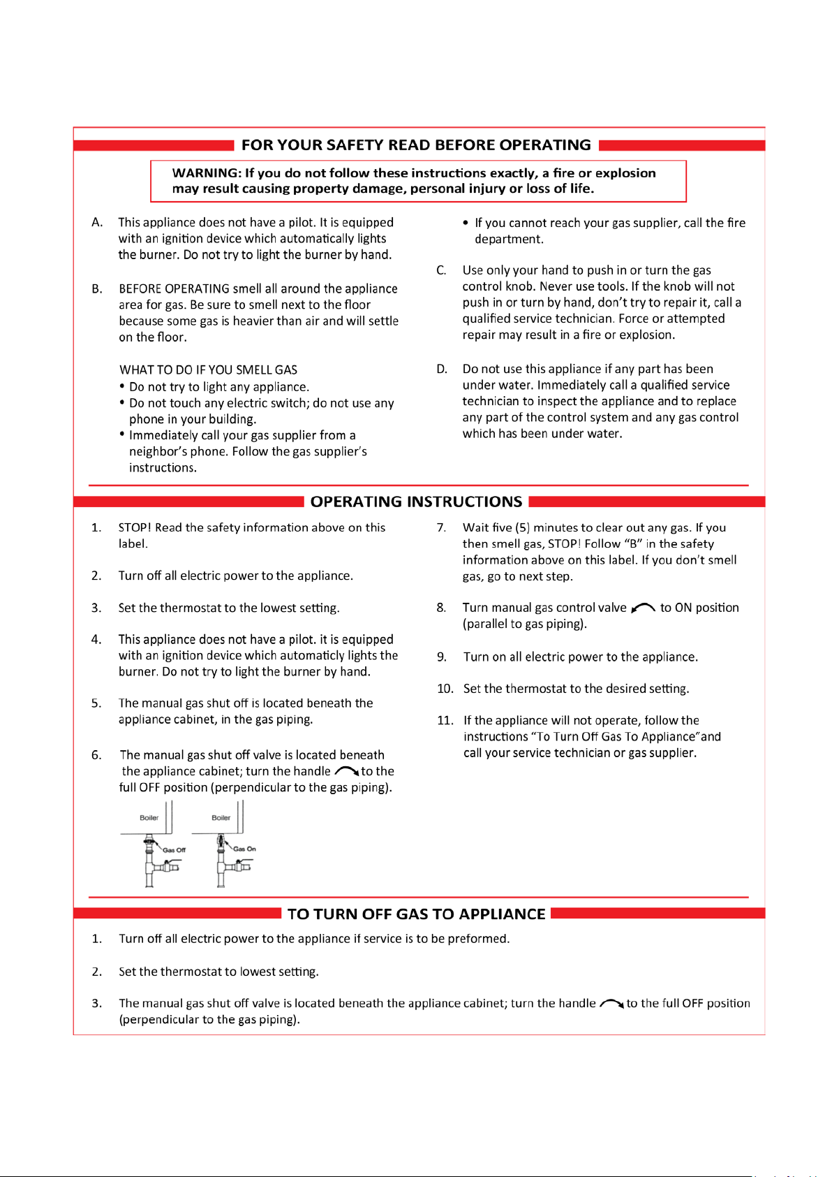
« A. Cet appareil ne comporte pas de veilleuse. Il est muni d'un dispositif d'allumage qui allume automatique-ment
le brûleur. Ne tentez pas d'allumer le brûleur manuellement.»
« B. AVANT DE FAI RE FO NCTIONNER , reniflez tout autour d e l'appar eil pour déceler une odeur de g az. Reniflez près du plancher, car certains gaz sont plus lourds que l'air et peuvent s'accumuler au niveau du sol. »
QUE FAIRE SI VOUS SENTEZ UNE ODEUR DE GAZ :
•Ne pas tenter d'allumer d'appareil.
•Ne touchez à aucun interrupteur; ne pas vous servir des téléphones se trouvant dans le bâtiment.
•Appelez immédiatement votre fournisseur de gaz depuis un voisin. Suivez les instructions du fournisseur.
•Si vous ne pouvez rejoindre le fournisseur, appelez le service des incendies.
E93.1901EN032 Installation and Service Manual SlantFin VGH-CH / CO 11
Page 12
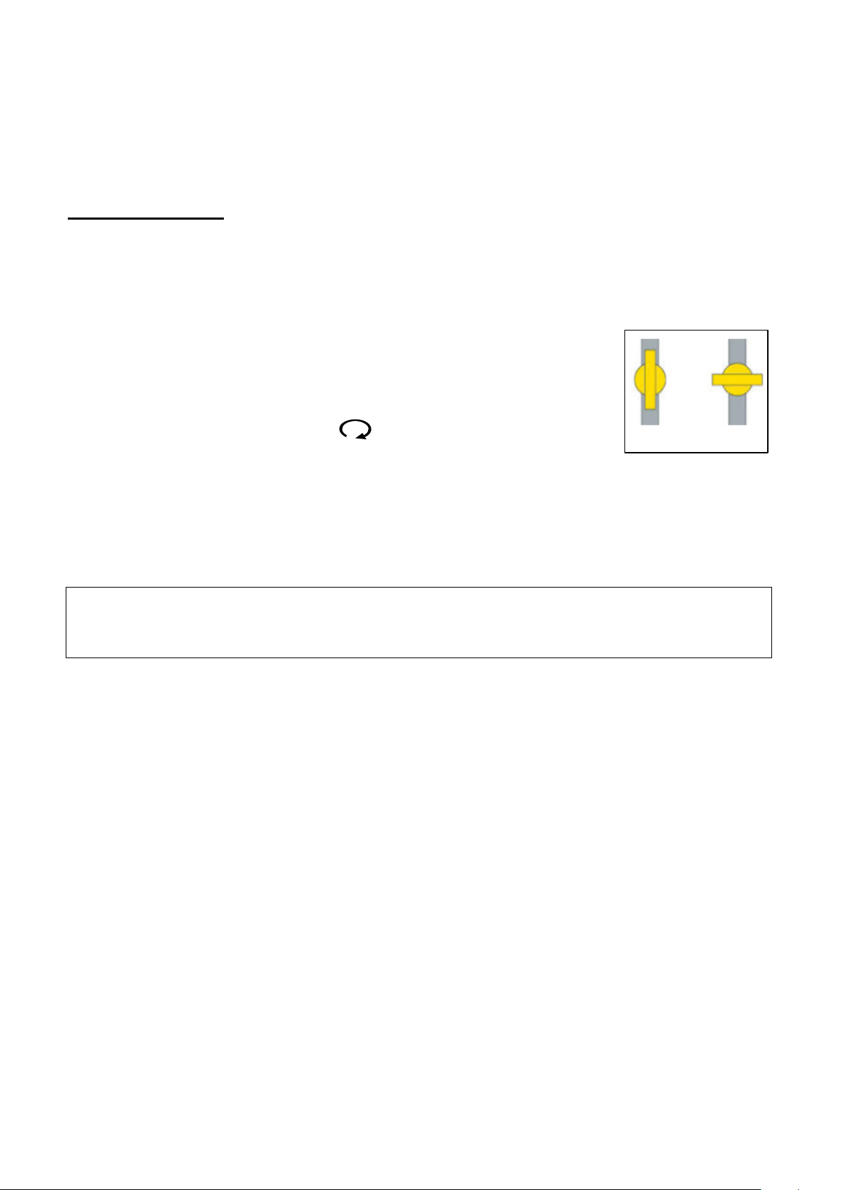
« C. Ne poussez o u to urne z la man ette d' a dm iss ion d u gaz qu'à l a m ain ; ne j a m ais ut il iser d' out il. S i la manette
OUVRIR FERMER
reste coincée, ne pas tenter de la réparer ; appelez u n technicien qualifié. Le fait de for cer la ma nette ou de la
réparer peut déclencher une explosion ou un incendie. »
« D. N'utilisez pas cet appareil s'il a été plongé dans l'eau, même partiellement. Faites inspecter l'appareil par un
technicien qualifié et remplacez toute partie du système de contrôle et toute commande qui ont été plongés dans
l'eau. »
Avertissement
Une installation, un r églage, une modificat ion, une réparation ou u n entretien non con-for me aux normes peut
entraîner des dommages matériels, des blessures (exposition à des matières dange-reuses) ou la mort.
L'installation et l'entretien doivent être effectués par un installateur ou un service d'entretien qualifié ou le
fournisseur de gaz (qui doivent avoir lu les instructions fournies avant de faire l'installation, l'en-tretien ou
l'enlèvement de la chaudière et les respecter. Cette chaudière contient des matériaux qui ont été iden-tifiés
comme étant cancérogènes ou pouvant l'être).
Comment couper l'admission de gaz de L’appareil:
1. Réglez le thermostat à la température la plus basse.
2. Coupez l'alimentation électrique de l'appareil s'il faut procéder à l'entretien
3. Le robinet d'arrêt de gaz est situé dessous la chaudière dans la conduite de gaz.
4. Tourner le robinet sens horaire à "OFF" (fermé) pour arrêter l’alimentation
en gaz. Ne pas forcer.
En cas de surchauffe ou s i l'admission de g az ne peut être coupée, ne pas c ouper ni débranc her l'aliment ation
électrique de la pompe. Fermer plutôt le robinet d'admission de gaz à l'extérieur de l'appareil.
Entretien et inspection
« Inspecter de faço n v isue ll e le s y s tème d'év ac ua tio n pour d ét erm in er l a gros s eu r et l'inclinaison hor iz ont ale qui
conviennent et s'assurer que le système est exempt d'obstruction, d'étranglement, de fuite, de corrosion et autres
défaillances qui pourraient présenter des risques. »
L'entretien et l'inspection de la chaud ière doivent être effectués aux occasions suivantes :
• Lorsqu'un certain nombre de codes d'erreur et/ou de verrouillage semblables apparaissent.
• Au moins tous les 12 mois, l'entretien doit être fait pour assurer un fonctionnement sûr et effic ace.
Les dommages causés par le manque d'entretien ne seront pas couverts par la garantie
Retrait d'une chaudière existante.
« Au moment du retrait d'une chaudière existante, les mesures suivantes doivent être prises pour chaque appareil
toujours raccordé au système d'évacuation commun et qui fonctionne alors que d'autres appareils toujours
raccordés au système d'évacuation ne fonctionnent pas :»
« Sceller toutes les ouvertures non utilisées du système d'évacuation. »
« Inspecter de façon visuelle le système d'évacuation pour déterminer la grosseur et l'inclinaison horizontale qui
conviennent et s'assurer que le système est exempt d'obstruction, d'étranglement, de fuite, de corrosion et autres
défaillances qui pourraient pr és enter des risqu es .
« Dans la mesure du poss ible, fermer toutes les port es et les fenêtres du bâtiment et tou tes les portes entre
l'espace où les apparei ls toujours raccordés au système d' évacuation sont installés et les autr es espaces du
bâtiment. Mettre en marc he les séc heuses, tous les appare ils non rac cordés au système d'év acuation c ommun
et tous les ventilateurs d'extraction comme les hottes de cuisinière et les ventilateurs des salles de bain. S'assurer
que ces ventilateurs fonct ionnent à la vitess e maximale. Ne pas fa ire fonctionner les ventilateurs d'été . Fermer
les registres des cheminées. » « Mettre l'appareil inspecté en marche. Suivre les instructions d'allumage. Régler
le thermostat de façon que l'appareil fonctionne de façon continue. »
« Une fois qu'il a été déterminé, selon la méthode indiquée ci-dessus, que chaque appareil raccordé au système
d'évacuation est m is à l'air libre de façon adé quate. Remettre les portes et les fenêtres, les ventilateurs, les
registres de cheminées et les appareils au gaz à leur position originale.
« Tout mauvais fonctionnement du système d'évacuation commun devrait être corrigé de façon que l'installation
soit conforme au N ational Fuel Gas Code, ANSI Z 223.1/NFPA 54 et (où) aux c odes d'installation CAN/CSAB149.1. Si la grosseur d'u ne s ection du s yst ème d'éva cuatio n doit être modifi ée, l e sys tème devrait être mo difi é
pour respecter les valeurs minimales des tableaux pertinents de l'appendice F du National Fuel Gas Code, ANSI
Z223.1/ NFPA 54 et (où) les codes d'installation CAN/CSA-B149.1. »
12 E93.1901EN032 Installation and Service Manual SlantFin VGH-CH / CO
Page 13

2 INTRODUCTION
1. Combi-boiler (CH & DHW)
2. Carbon mo noxid e
This manual is the installation and service manual for the high-efficiency heating systems from the VGH-CH
(Central Heating boi lers) series and VGH-CO (Combi boilers) series. This manual is spec ifically written for the
installer.
The distributor and manufacturer ar e not ac countable for any damag e c aused by installers not correctly following
these instructions.
For service and repair purposes use only original Slant/Fin spare parts.
All documentation produced by the manufacturer is subject to copyright law.
This manual is subject to change without notice.
Terms and abbreviations
In this manual the following terms and abbreviations are used:
A (Amp) Ampère
AFUE Annual Fuel Utilization Efficiency
AHRI Air-conditioning, Heating and Refrigeration Institute
ANSI American National Standards Institute
ASME American Society of Mechanical Engineers
ASSE American Society of Sanitary Engineering
bar Unit of pressure (1 bar = 14.5 PSI)
BCU Burner Control Unit
BTU British Thermal Unit
°C Degree Celsius
CaCO3 Calcium carbonate
CH Central Heating.
CO
CO2 Carbon dioxide
Combi A boiler providing a combination of central heating and domestic hot water
CVPC Chlorinated Polyvinyl Chloride, a thermoplastic
DHW Domestic Hot Water
°F Degree Fahrenheit
Hz Hertz
LB Digit-based Liquid Crystal Display Board
LCD Liquid Crystal Display
LPG Liquefied Petroleum Gas
MBH 1000 BTUs per hour
mg Milligram
NFPA National Fire Protection Association
NOx Mono-nitrogen oxides
NPT National Pipe Thread, American standard for threaded pipes and fittings
NTC Negative Temperature Coe fficie nt, a quality of sensors and resistors
O
2
PB Graphical Display Board
Oxygen
E93.1901EN032 Installation and Service Manual SlantFin VGH-CH / CO 13
Page 14

PCB Printed Circuit Board
• ASME Boiler and Pressure Vessel Code
Section “Heating boilers”
• ASME Boiler and Pressure Vessel Code
Section “Recommended Rules for the Care and Operation of
Heating Boilers”
• ANSI Z223.1 / NFPA 54
National Fuel Gas Code
• ANSI / NFPA 70
National Electrical Code
• ANSI / NFPA 211
Chimneys, Fireplaces, Vents and Solid Fuel Burning
Appliances
PEX Cross-linked polyethylene
pH Acidity degree
PID Proportional Integral Derivative, a control concept used in automation
ppm Particles per million
psi Pounds per square inch, a unit of pressure
Pump Circulator
PVC Polyvinyl Chloride, a thermoplastic
PWM Pulse Width Modulation
RCF Refractory Ceramic Fibers
RT Room Thermostat
TDS Total Diss olv e d Solids, a characteristic used in water quality
UL Underwriters Laboratories, American testing and certification institute
VAC Volt Alternating Current
VDC Volt Direct Current
W Watt, a unit of power
W.C. Water column
Codes, standards and regulations
Installation, maintenance and repairs must be performed in strict accordance with the state and local requirements
and regulations.
In the absence of local requirements, the following standards and regulations apply:
Where required by the authority having jurisdiction, the installation must conform to the Standard for Controls and
Safety Devices for Automatically Fired Boilers, ANSI, ASME CSD-1.
Maintenance and inspection
For a good, safe and long-lasting operation of the boi ler and to maintain warranty it is m andatory to carry out
inspection, maintenance and service on the boiler at least once a year.
Maintenance and inspection of the boiler must be carried out in the following situations:
• When a number of similar error codes and/or lockouts appear.
• At least once every 12 months to ensure safe and efficient operation.
Damage caused by lack of maintenance will not be covered under warranty.
Visually inspect the venting system for pro per size and horizonta l pitch and determine ther e is no blockage or
restriction, leakage, corrosion or other deficiencies which could cause an unsafe condition.
More details on maintenance, inspections and repairs are cover ed in chapter 18.
14 E93.1901EN032 Installation and Service Manual SlantFin VGH-CH / CO
Page 15

For installations in the Commonwealth of Massachusetts
The following local requirements apply in addition to all other applicable NFPA requirements:
For direct-vent boilers, mec hanical-vent heat ing appliances or domestic hot water equi pment, where the bott om
of the vent termina l and the intake is installed below four feet above grade, th e following requ irements mus t be
met:
1) If not present o n each floor level wher e there are be drooms, a car bon monox ide det ector an d alarm must
be placed in a living area outside the bedrooms. The carbon monoxide detector and alarm must comply with
NFPA 720 (2005 Edition).
2) A carbon monoxide detector and alarm must be located in the room that houses the boiler and/or
equipment and must:
a) be powered by the same electrical circuit as the boiler and/or equipment so that only one service switch
services both the boiler and the carbon monoxide detector;
b) have battery back-up power;
c) meet ANSI/UL 2034 Standards and comply with NFPA 720 (2005 Edition); and
d) have been approved and listed by a Nationally Recognized Testing Lab as recognized under 527 CMR.
3) A product-approve d vent terminal must be us ed, and if applicable, a pro duct approved air intak e must be
used. Installation must be performed in strict compliance with the manufacturer’s instructions. A copy of the
installation instructions must remain with the boiler and/or equipment at the completion of the installation.
4) A metal or plastic identification plate must be mounted at the exterior of the building, four feet directly above
the location of ve nt ter mina l. The plate must be of suffic ient size to be eas ily read from a dis tance of eigh t
feet away and read “Gas Vent Directly Below”.
For direct-vent boilers mechanical-vent heating boilers or domestic hot water equipment, where the bottom of the
vent terminal and the intake is installed higher than four feet above grade, the following requirements must be met:
1) If not present o n each floor level wher e there are be drooms, a car bon monox ide det ector an d alarm must
be placed in a living area outside the bedrooms. The carbon monoxide detector and alarm must comply with
NFPA 720 (2005 Edition).
2) A carbon monoxide detector must:
a) be located in the room where the boiler and/or equipment is located;
b) be either hard-wired or battery powered or both; and:
c) comply with NFPA 720 (2005 Edition).
3) A product-approve d vent te rminal mus t be used, a nd if applicab le, a produc t- approved air intak e must be
used. Installation must be in strict compliance with the manufacturer’s instructions. A copy of the installation
instructions must remain with the boiler and/or equipment at the completion of the installation.
E93.1901EN032 Installation and Service Manual SlantFin VGH-CH / CO 15
Page 16

3 TECHNI CAL DATA VGH RESIDENTIAL BOILERS
On/Off thermostat or modulating thermostat
Low Water Cut Off
System circulator
Alarm outputs
On/Off thermostat or modulating thermostat
Low Water Cut Off
System circulator
Alarm outputs
FUNCTIONAL INTRODUCTION
The VGH b oilers are cent ral heatin g/combi boilers w ith a maximu m high effici ency. Such a performance c an be
reached by, amongst o ther things, using a sp ecial heat exchanger m ade of stainless stee l. This allows the flue
gases to cool down below the condensation point, thus releasing extra heat. This has an immediate positive impact
on the efficiency.
The VGH boiler is factory set for Natural gas.
Fuel used must have Sulphur rates with a maximum a nnual peak over a s hort pe riod of tim e of 150 mg/m
3
ppm) and an annual average of 30 mg/m
. (22 ppm average).
Boiler control includes:
Cascade control for up to sixteen boilers
Remote operation and heat demand indication from each boiler
Weather compensation control – Outdoor reset.
Indirect tank control (On heat only boiler models)
Connections for VGH-CH boilers:
3
(110
0-10 VDC remote flow temperature (set point) control
0-10 VDC remote boiler input control
Outdoor temperature sensor
External indirect tank circulator or diverter valve
PWM control for external boiler circulator.
Connections for VGH-CO boilers:
0-10 VDC remote flow temperature (set point) control
0-10 VDC remote boiler input control
Outdoor temperature sensor
PWM control for external boiler circulator.
External flow switch or external safety device.
Modbus
External system sensor
DHW indirect sensor or aquastat.
External Ignition coil
External flow switch or external safety device.
Modbus
External system sensor
External Ignition coil
16 E93.1901EN032 Installation and Service Manual SlantFin VGH-CH / CO
Page 17

Information
Software Versions
Error Log
Figure 3.1
Software Versions
Display [63EF 83BC]
Figure 3.2
Figure 3.3
Location of version numbers
Burner Controller Hardware Version
– To be found on the second line of the white sticker on the side of the burner controller.
e.g. 957MN15_3Rh4b
Burner Controller Software Versions
• Press the menu button
• Go to Information
• Go to Software Versions.
Boiler Status
Boiler History
i
Boiler [5C79 14A9]
Device Group 900MN
E93.1901EN032 Installation and Service Manual SlantFin VGH-CH / CO 17
Page 18

Technical specifications datasheets
IV
p nom inch W.C. (mbar)
p min inch W.C. (mbar)
p max inch W.C. (mbar)
Natural gas
7.0 (17.4)
3.5 (8.7)
10.5 (26.2)
Propane
11.0 (27.4)
8.0 (19.9)
13.0 (32.4)
Table 3. 1
TECHNICAL SPECIFICATIONS VGH-80-CH / VGH-90-CO / VGH-100-CH
GENERAL
Boiler category Type boiler VGH-80-CH VGH-90-CO VGH-100-CH
Dimensions (h x w x d) inch (mm) 28.2" x 17.4" x 16.9" (717mm x 442mm x 429mm)
Water content
gallon
(liter)
0.37 (1.4) 0.37 (1.4) 0.4 (1.75)
Weight (empty) lbs (kg) 74 (34) 77 (35) 77 (35)
Supply/return connection
CH
Supply/return connection
DHW
inch NPT ¾” NPT ¾” NPT ¾”
inch
NPT ¾” NPT ½” NPT ¾”
Gas connection inch NPT ¾” NPT ¾” NPT ¾”
Flue connection inch (mm) 3” (80mm) 3” (80mm) 3” (80mm)
GAS CONSUMPTION Values min-max:
Natural gas
Propane
1
Gas supply
Nat. gas
ft3/h
m3/h
ft3/h
3
/h
m
Inch W.C./
(mbar)
7.43 – 74.3
0.21 – 2.11
3.20 – 32.0
0.09 – 0.91
8.36 – 83.6
0.24 – 2.37
3.60 – 36.0
0.10 – 1.02
7.0 (17.4)
9.29 – 92.9
0.26 – 2.63
4.0 – 40.0
0.11 – 1.13
pressure
nominal 2
Propane
Inch W.C./
(mbar)
11.0 (27.4)
NOTES
1
Using propane, maximum fan speed needs to be reduced
2 Min. and max. gas supply pressures are listed in the table below.
18 E93.1901EN032 Installation and Service Manual SlantFin VGH-CH / CO
Page 19

Type boiler VGH-80-CH VGH-90-CO VGH-100-CH
Low Fire %
9.4 – 8.9
High Fire %
9.1 – 8.4
Low Fire %
9.8
High Fire %
10.1
Low Fire %
4.1 – 5.0
High Fire %
4.6 – 6.0
Low Fire %
6.0
High Fire %
5.5
Flue gas temperature at
70 °F (20 °C)
INSTALLATION
∆T = 20 F
26.3 (8.0)
26.3 (8.0)
35.6 (10.9)
T = 35 F
8.8 (2.7)
8.8 (2.7)
12.7 (3.9)
Pressure boiler min-max.
psi (bar)
11.6 – 43.5 (0.8 – 3.0)
Max. supply temperature
°F (°C)
194 (90)
flow rate at ∆T = 77 °F
gal/min (l/min)
-
2.3 (8.7)
-
Pressure DHW min-max
psi (bar)
-
14.5 - 116 (1.0 -8.0)
-
ELECTRIC
Minimum power consumption
W
140
140
140
Maximum power consumption
W
180
190
180
Power supply
V/Hz
120 / 60
Protection class
-
IPX4D5
Table 3. 2
Figure 3.6
IPX4D Air inlet.
Two 90° Bends with a bird screen
Boiler is IP20
applying a bird
Natural gas
CO2 flue gas
3
Propane
Natural gas
O2 flue gas
3
Propane
combustion air temperature =
Available pressure for the flue
and inlet system 4
Resistance
boiler
∆
°F (°C) 86 – 153 (30 – 67)
Inch W.C.
(Pa)
ft.head (m.W.C.)
ft.head (m.W.C.)
250 320 230
DHW PERFORMANCE
Thermal Efficiency 6 % 95.0
Standby power consumption W 6 6 6
NOTES
3
CO2 or O2 of the unit measured/set without the boiler front panel in place
4
Maximum allowed combined resistance of flue gas and air supply piping at high fire
5
For gas appliance type B23(P) (Room Air) only class IPX4D with special air inlet, otherwise the
protection class is IP20 (see also picture below)
6
Efficiency of DHW performance measured according to ANSI Z21.10.3-2015 • CSA 4.3-2015
screen only
E93.1901EN032 Installation and Service Manual SlantFin VGH-CH / CO 19
Page 20

TECHNICAL SPECIFICATIONS VGH-120-CH / VGH-150-CO / VGH-150-CH
IV
Type boiler
VGH-120-CH
VGH-150-CO
VGH-150-CH
p nom inch W.C. (mbar)
p min inch W.C. (mbar)
p max inch W.C. (mbar)
Natural gas
7.0 (17.4)
3.5 (8.7)
10.5 (26.2)
Propane
11.0 (27.4)
8.0 (19.9)
13.0 (32.4)
Table 3. 3
GENERAL
Boiler category -
Dimensions (h x w x d) Inch (mm) 28.2" x 17.4" x 16.9" (717mm x 442mm x 429mm)
Water content
Gallon
(liter)
0.55 (2.1) 0.55 (2.1) 0.83 (3.15)
Weight (empty) Lbs (kg) 83 (38) 86 (39) 97 (44)
Supply/return connection
CH
Supply/return connection
DHW
inch NPT ¾” NPT ¾” NPT ¾”
inch
NPT ¾” NPT ½” NPT ¾”
Gas connection inch NPT ¾” NPT ¾” NPT ¾”
Flue connection Inch (mm) 3” (80mm) 3” (80mm) 3” (80mm)
GAS CONSUMPTION Values min-max:
Natural gas
Propane
1
Gas supply
Nat. gas
ft3/h
m3/h
ft3/h
3
/h
m
Inch W.C./
(mbar)
11.1 – 111.5
0.32 – 3.16
4.8 – 48.0
0.14 – 1.36
13.9 – 139.4
0.40 – 3.95
6.0 – 60.0
0.17 – 1.7
7.0 (17.4)
13.9 – 139.4
0.40 – 3.95
6.0 – 60.0
0.17 – 1.7
pressure
nominal 2
Propane
Inch W.C./
(mbar)
11.0 (27.4)
NOTES
1
Using propane, maximum fan speed needs to be reduced
2 Min. and max. gas supply pressures are listed in the table below.
20 E93.1901EN032 Installation and Service Manual SlantFin VGH-CH / CO
Page 21

Type boiler VGH-120-CH VGH-150-CO VGH-150-CH
Flue gas temperature at
70 °F (20 °C)
T = 35 F
Efficiency of DHW performance measured according to ANSI Z21.10.3-2015 • CSA 4.3-2015
Table 3. 4
Natural gas
Low Fire % 9.4 – 8.9
CO2 flue gas
3
High Fire % 9.1 – 8.4
Low Fire % 9.8
Propane
High Fire % 10.1
Low Fire % 4.1 – 5.0
Natural gas
O2 flue gas
3
High Fire % 4.6 – 6.0
Low Fire % 6.0
Propane
High Fire % 5.5
combustion air temperature =
Available pressure for the flue
and inlet system 4
°F (°C) 86 – 153 (30 – 67)
Inch W.C.
(Pa)
260 400 340
INSTALLATION
Resistance
boiler
∆T = 20 F
∆
ft.head (m.W.C.)
ft.head (m.W.C.)
25.2 (7.7) 25.2 (7.7) 47.6 (14.5)
9.7 (3.9) 9.7 (3.9) 15.8 (4.8)
Pressure boiler min-max. psi (bar) 11.6 – 43.5 (0.8 – 3.0)
Max. supply temperature °F (°C) 194 (90)
DHW PERFORMANCE
flow rate at ∆T = 77 °F
gal/min (l/min) - 3.4 (12.9) Pressure DHW min-max psi (bar) - 14.5 - 116 (1.0 -8.0) Thermal Efficiency 6 % 93.7
ELECTRIC
Minimum power consumption W 140 140 140
Maximum power consumption W 190 220 200
Standby power consumption W 6 6 6
Power supply V/Hz 120 / 60
Protection class - IPX4D5
NOTES
3
CO2 or O2 of the unit measured/set without the boiler front panel in place.
4
Maximum allowed combined resistance of flue gas and air supply piping at high fire
5
For gas appliance type B23(P) (Room Air) only class IPX4D with special air inlet, otherwise the
protection class is IP20 (see also picture at page 19)
6
E93.1901EN032 Installation and Service Manual SlantFin VGH-CH / CO 21
Page 22

TECHNICAL SPECIFICATIONS VGH-180-CH / VGH-200-CO
IV
Type boiler
VGH-180-CH
VGH-200-CO
p nom inch W.C. (mbar)
p min inch W.C. (mbar)
p max inch W.C. (mbar)
Propane
11.0 (27.4)
8.0 (19.9)
13.0 (32.4)
Table 3. 5
GENERAL
Boiler category -
Dimensions (h x w x d) Inch (mm) 28.2" x 17.4" x 16.9" (717mm x 442mm x 429mm)
Water content
Gallon
(liter)
0.83 (3.15) 0.83 (3.15)
Weight (empty) Lbs (kg) 98 (44) 101 (46)
Supply/return connection
CH
Supply/return connection
DHW
inch NPT ¾” NPT ¾”
inch
NPT ¾” NPT ½”
Gas connection inch NPT ¾” NPT ¾”
Flue connection Inch (mm) 3” (80mm) 3” (80mm)
GAS CONSUMPTION Values min-max:
Natural gas
Propane
1
Gas supply
Nat. gas
ft3/h
m3/h
ft3/h
3
/h
m
Inch W.C./
(mbar)
16.7 – 167.4
0.47 – 4.74
7.2 – 72.1
0.2 – 2.04
18.6 – 186.0
0.52 – 5.26
8.0 – 80.0
0.23 – 22.7
7.0 (17.4)
pressure
nominal 2
Propane
Inch W.C./
(mbar)
11.0 (27.4)
NOTES
1
Using propane, maximum fan speed needs to be reduced.
2 Min. and max. gas supply pressures are listed in the table below.
Natural gas 7.0 (17.4) 3.5 (8.7) 10.5 (26.2)
22 E93.1901EN032 Installation and Service Manual SlantFin VGH-CH / CO
Page 23

Type boiler
VGH-180-CH
VGH-200-CO
CO2 flue gas
Low Fire %
9.4 – 8.9
High Fire %
9.1 – 8.4
Low Fire %
9.8
High Fire %
10.1
Low Fire %
4.1 – 5.0
High Fire %
4.6 – 6.0
Low Fire %
6.0
High Fire %
5.5
Inch W.C.
(Pa)
INSTALLATION
T = 20 F
68.4 (20.8)
68.4 (20.8)
T = 35 F
22.6 (6.9)
22.6 (6.9)
Pressure boiler min-max.
psi (bar)
11.6 – 43.5 (0.8 – 3.0)
Max. supply temperature
°F (°C)
194 (90)
DHW PERFORMANCE
flow rate at ∆T = 77 °F
gal/min (l/min)
-
4.6 (17.4)
Pressure DHW min-max
psi (bar)
-
14.5 - 116 (1.0 -8.0)
Thermal Efficiency 6
%
95.4
ELECTRIC
Minimum power consumption
W
150
150
Maximum power consumption
W
260
290
Standby power consumption
W 6 6
Power supply
V/Hz
120 / 60
Protection class - IPX4D5
NOTES
Efficiency of DHW performance measured according to ANSI Z21.10.3-2015 • CSA 4.3-2015
Table 3. 6
O2 flue gas
3
3
Natural gas
Propane
Natural gas
Propane
Flue gas temperature at combustion air
temperature = 70 °F (20 °C)
Available pressure for the flue and inlet system 4
Resistance
boiler
3
CO2 or O2 of the unit measured/set without the boiler front panel in place
4
Maximum allowed combined resistance of flue gas and air supply piping at high fire
5
For gas appliance type B23( P) (Room Air) only class IPX4D with special air inlet, otherwise the
∆
∆
°F (°C) 86 – 153 (30 – 67)
400 490
ft.head (m.W.C.)
ft.head (m.W.C.)
protection class is IP20 (see also picture at page 19)
6
E93.1901EN032 Installation and Service Manual SlantFin VGH-CH / CO 23
Page 24

NOTICE
High altitude operation
High Altitude Operation
Elevations
2000 ft (610 m)
3000 ft (914 m)
4000 ft (1219 m)
4500 ft (1372 m)
Above 4500 ft (1372 m)
In USA
No de-rate
De-rate by 4 %
De-rate by 8 %
De-rate by 10 %
De-rate 4% per 1000 ft.
In Canada
No de-rate
De-rate by 10%
De-rate by 10 %
De-rate by 10 %
De-rate 4% per 1000 ft.
Model number
Min
Max
Combustion – At elevations above 2000 ft (610 m), the combustion of the appliance must be checked with
kits are neede d, sinc e the 1: 1 Gas /A ir ra tio o f th e gas v alv e and th e ven tu ri w ill re spo n d
instructions may result in property damage, serious injury, or death.
Table 3. 7
Table 3. 8
Boiler model
number
pressure
temperature*
capacity
surface
VGH-80-CH /
VGH-90-CO
461953
T4804.4CL
50 Psi
210 °F
91 MBH
7.99 SQTF
VGH -100-CH
461955
T4804.4CL
50 Psi
210 °F
136 MBH
9.99 SQFT
VGH -120-CH
/ VGH-150-CO
461959
T4806.4CL
50 Psi
210 °F
182 MBH
11.99
SQFT
VGH-150-CH /
VGH-200-CO
461963
T4807.4CL
50 Psi
210 °F
227 MBH
17.98
Table 3. 9
The boiler is designed to operate at its maximum listed capacity in installations at elevations less than or equal to 2000 ft
(610 m) above Sea Level. Since the density of air decreases as elevation increases, maximum specified capacity will be
de-rated for elevations above 2000 ft (610 m) in accordance with the table underneath.
In USA and Canada, de-rate by 4% extra for every 1000 ft. above 4500 ft.
a calibrated (altitude corrected) combustion analyzer to ensure safe and reliable operation. No orifices o r
high-altitude
automatically to reduced air pressure.
It is the Installers responsibility to check the combustion of the appliance. Failure to follow these
How to calculate De-rating at intermediate elevations for US:
Elevation between:
2000 and 3000 ft : (New value – 2000) x 0.004 Example: Elevation is 2600 ft. De-rating is (2600-2000)x0.004 = 2.4 %
3000 till 4000 ft : ((New value – 3000) x 0.004)+4 Example: Elevation is 3700 ft. De-rating is ((3700-3000)x0.004)+4 = 6.8 %
4000 till 4500 ft : ((New value – 4000) x 0.004)+8 Example: Elevation is 4200 ft. De-rating is ((4200-4000)x0.004)+8 = 8.8 %
Above 4500 ft : ((New value – 4500) x 0.004)+10 Example: Elevation is 4800 ft. De-rating is ((4800-4500)x0.004)+10 = 11.2 %
How to calculate De-rating at intermediate elevations for Canada:
Elevation between:
2000 till 4500 ft : All values de-rate by 10% Example: Elevation is 3600 ft. De-rating = 10 %
Above 4500 ft : ((New value – 4500) x 0.004)+10 Example: Elevation is 7600 ft. De-rating is ((7600-4500)x0.004)+10 = 22.4 %
DHW specifications VGH-CO series
VGH-CO series DHW specifications
DHW Input, MBH
VGH-90-CO 9 90
VGH-150-CO 15 150
VGH-200-CO 20 200
Heat exchanger inform ati on
The heat exchanger in this boiler is manufactured and certified by Sermeta.
This table gives an overview of the ASME-H specifications as certified:
CRN
Max
allowable
water
Max
allowable
water
Min relieve
valve
Heat exch.
VGH-180-CH /
* the maximum supply temperature of the boiler is 194F
24 E93.1901EN032 Installation and Service Manual SlantFin VGH-CH / CO
SQFT
Page 25

Specifications input, output, efficiency (AHRI)
Min
Max
The ratings and efficiencies are based on standard test procedures and calculation methods as prescribed by the
Table 3. 10
Model
number
CH Input, MBH
1
Output
MBH
1
AHRI
AFUE
Net Ratings Water, MBH
VGH-80-CH 8 80 74 64 95.2
VGH-90-CO 9 80
74 64 95.2
VGH-100-CH 10 100 93 81 95.2
VGH-120-CH 12 120 111 97 95.2
VGH-150-CO 15 120 111 97 95.2
VGH-150-CH 15 150 140 122 95.2
VGH-180-CH 18 180 168 146 95.2
VGH-200-CO 20 180 168 146 95.2
1
Listed Input and Output ratings are at minimum vent lengths at Sea Level. Numbers will be lower with longer
venting and/or altitudes greater than 2000 feet [610 m].
• Ratings have been confirmed by the Hydronics Section of AHRI.
•
United States Department of Energy.
%
E93.1901EN032 Installation and Service Manual SlantFin VGH-CH / CO 25
Page 26
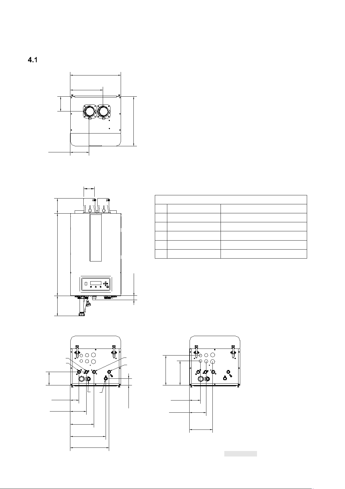
4 BOILER DIMENSIONS
A
Supply CH
B
Indirect DHW
C
Gas
D
Indirect DHW
E
Return CH
F
Condensate
Figure 4.1
165 mm
[6.5 in]
285 mm
[11.22 in]
129 mm
[5.07 in]
130 mm
[5.12 in]
176 mm
[6.93 in]
DN80 mm (2x)
[3 in]
116 mm
[4.57 in]
59 mm
[2.33 in]
76 mm
[2.99 in]
141 mm
[5.55 in]
310 mm
[12.2 in]
339 mm
[13.35 in]
F
717 mm
[28.23 in]
259 mm
[10.2 in]
212 mm
[8.33 in]
96 mm
[3.78 in]
146 mm
[5.75 in]
202 mm
[7.96 in]
D
E
C
A
B
37 mm
[1.48 in]
207 mm
[8.17 in]
430 mm
[16.93 in]
442 mm
[17.4 in]
VGH-80-CH / VGH-100-CH / VGH-120-CH / VGH-150-CH / VGH-180-CH
Connections VGH-CH boilers
NPT ¾ “
NPT ¾ “
NPT ¾ “
NPT ¾ “
NPT ¾ “
Flexible hose Ø 1.06” (26.9 mm)
26 E93.1901EN032 Installation and Service Manual SlantFin VGH-CH / CO
Page 27

A
Supply CH
B
Supply tap water
C
Gas
D
Return tap water
E
Return CH
Figure 4.2
212 mm
[8.33 in]
259 mm
[10.2 in]
96 mm
[3.78 in]
146 mm
[5.75 in]
202 mm
[7.96 in]
E
D
C
A
B
116 mm
[4.57 in]
76 mm
[2.99 in]
141 mm
[5.55 in]
F
207 mm
[8.17 in]
274 mm
[10.79 in]
339 mm
[13.35 in]
176 mm
[6.93 in]
38 mm
[1.48 in]
717 mm
[28.23 in]
130 mm
[5.12 in]
DN80mm (2x)
[3 in]
442 mm
[17.4 in]
430 mm
[16.93 in]
129 mm
[5.07 in]
165 mm
[6.5 in]
285 mm
[11.22 in]
VGH-90-CO / VGH-150-CO / VGH-200-CO
Connections VGH-CO boilers
NPT ¾ “
NPT ½ “
NPT ¾ “
NPT ½ “
NPT ¾ “
F Condensate Flexible hose Ø 1.06” (26.9 mm)
E93.1901EN032 Installation and Service Manual SlantFin VGH-CH / CO 27
Page 28
5 ACCESSORIES AND UNPACKING
Item
Part number
Safety Flow Switch kit
81 7106 000
IP module
81 7111 000
Software + interface cable for programming the boiler with a computer/laptop
81 7135 000
External Ignition transformer with special burner controller; VGH-80-CH to VGH-120-CH
81 7276 000
External Ignition transformer with special burner controller; VGH-150-CH and VGH-180-CH
81 7277 000
External Ignition transformer with special burner controller; VGH-90-CO
81 7278 000
External Ignition transformer with special burner controller; VGH-150-CO
81 7279 000
External Ignition transformer with special burner controller; VGH-200-CO
81 7280 000
Special air inlet for IPX4D protection on B23(P) (Room Air) boilers
81 7281 000
Propane conversion kit VGH-80-CH and VGH-90-CO
81 7271 000
Propane conversion kit VGH-100-CH
81 7272 000
Propane conversion kit VGH-120-CH and VGH-150-CO
81 7273 000
Propane conversion kit VGH-150-CH
81 7275 000
Propane conversion kit VGH-180-CH
81 7274 000
Propane conversion kit VGH-200-CO
81 7304 000
VGH Residential Plumbing Kit Heating Only Boiler (VGH-xx-CH)
81 7154 000
VGH Residential Plumbing Kit Combi Boiler (VGH-xx-CO).
81 7155 000
Tank sensor for an Indirect Hot Water tank
81 7110 000
External flow temperature sensor for behind the low header 10kOhm@77°F
81 7109 000
MagFilter Pro XL
81 7284 000
Mag Flush Pro
81 7132 000
Heating System Cleaner
81 7133 000
Heating System Protector
81 7134 000
VGH Residential Yearly Maintenance Service Kit
81 7285 000
French I&O Manual Residential Boiler
81 7282 000
French User Manual residential Boiler
81 7283 000
Qty Description
Part number
1
Startup and commissioning check list
---
1
Wall bracket with locking plate and bolts
81 7264 000
3
Spare nuts for the burner plate (in a bag attached to the front of the gas valve)
See spare part list
1
Spare fuse for the boiler control (at the burner controller)
See spare part list
1
Bottom part of the condensate drain assembly
81 7263 000
1
Pressure/temperature residential VGH control kit
81 7288 000
This kit consists of
1 ASME pressure 30 psi relief valve (packed into an additional box)
65 0550 000
1 Outdoor (air) temperature sensor: 10kOhm@25°C -B3977
81 7108 000
1 Temperature and pressure gauge
91 0373 061
1 ¾ Gas shut off ball valve
83 3803 000
1 Boiler Drain
40 0201 000
1 Warranty card
41 1189 000
1 VGH Residential Installation and Service manual
81 7286 000
1 VGH Residential User Manual
81 7287 000
Table 5. 1
Table 5. 2
Optional Accessories
Depending on the selected boiler type, the selected controlling behavior for the central heating system and/or the
optional use of an indirect tank, the following items are available as accessories. Contact your supplier for ordering.
Supplied with the boiler
The VGH boiler will be supplied with the following documents and accessories:
After delivery, always check the boiler package to see if it is complete and without any defects. Report any defects
or missing parts immediately to your supplier.
28 E93.1901EN032 Installation and Service Manual SlantFin VGH-CH / CO
Page 29
CAUTION
6 INSTALLATION LOCATION OF THE VGH
The installation of the gas appliance must conform to the requirements of this manual and your
CSD-1
The wall used for mou nting t he b oiler must be ab le to hol d the weight of th e boile r, pipin g and
a (optional cascade) stand.
NOTICE
General
The boiler must be posit ioned and installed by a qua lified installer or the gas company in acc ordance with all
applicable standards , local codes and regulat ions (see also paragrap h 2.2). Commissioning of t he b oi ler must be
done by a qualified installer or technician, who has been trained for this type of boiler.
Boiler Installation Location Requirements
The installation of the boiler must meet the following location requirements:
• The installation of this boiler when installed using room air must comply with NFPA 54.
• The flue gas pipes must be connected to the outside wall and/or the outside roof, see chapter 9.
• The installation area must be dry and frost-free.
• The boiler has a built-in fa n that will generate noise, depending on the tota l heat demand. The boiler
location must minimize any disturbance this might cause. Preferably mount the boiler on a solidly
constructed wall or stand.
• There must be sufficient lighting available in the boiler room to work safely on the boiler.
• When a boiler is position ed at the highes t point of the installation, th e supply and return pipes mus t first
protrude 20” above the top of the boiler, before these pipes go to the installation side. In other words, the
water level must always be 20” above t he top o f the b oiler an d an auto mat ic air v ent mus t be inst alled i n
the supply or return pipe. It is recommended to install a low water cut off above the boiler, when the boiler
is installed above the system or at the highest po int in the insta llatio n.
• Do not install the boiler in a location where it will be exposed to temperatures of 100 °F or higher.
• Do not install the boiler in a location where it w ill be exposed t o high levels of humi dity and moisture or
where condensation might fall onto the boiler.
• Make sure there is an open connection to the s ewer to drain the c ondensate. This conn ection must be
lower than the condensate drains level of the boiler. If not, a condensate pump will be required.
• Do not locate the boiler in an area which contains corrosive or other contaminants as outlined in section
9.8.1, especially Table 9.11 and Table 9.12.
• When considering installation locations, consideration must be given to the combustion air supply,
specifically whether to use indoor air or sealed combustion.
• Do not allow the combustion air to come from a source or area which contains corrosive or other
contaminants as outlined in section 9.8.1, especially Table 9.11 and Table 9.12.
The boiler must be positioned and installed by a qualified installer or gas company in accordance with all applicable
standards, local codes and regulations. Commissioning of the boiler must be done by a qualified installer or
technician, who has been trained for this type of boiler.
In the Commonwealth of Massachusetts this boiler must be installed by a licensed Plumber or Gas Fitter.
The installation area/room must have the following provisions:
• 120 V - 60 Hz power source socket with ground.
• Open connection to the sewer system for draining condensing water.
• A wall or stand to properly support the weight of the boiler.
• Depending on the current of the used circulator, apply a circuit break er betw e en 6 and 12 amps
local authority. Where required by the authority having jurisdiction, the installation must conform
to the standard for Controls and Safety Devices for Automatically Fired Boilers ANSI/ASME
fittings, and the we ight of the w ater. If not, it is r ec ommend ed to mount t he boi ler by means of
The boiler must NOT be installed on or near carpeting.
E93.1901EN032 Installation and Service Manual SlantFin VGH-CH / CO 29
Page 30

Model No.
Clearances to wall, ceiling and floor
A: Front
B: Top
C: Sides
D: Back
E: Bottom
Minimum required
clearances
Recommended
service clearances
Clearances from combustible materials
2. Vent pipe – at least 1" (25 mm) from combustible materials.
* See closet / enclosure installation.
Table 6. 1
Figure 6.1
Ceiling
A
Wall
E
B
C
C
D
A
Installation Clearances
When installing the boiler, the following table shows the clearances which are required, and which clearances are
recommended considering service and maintenance. If the recommended clearances are not provided service or
maintenance on the boiler might not be possible without removing the boiler from its space.
VGH-80-CH
Distances – inches
VGH-100-CH
VGH-120-CH
VGH-150-CH
VGH-180-CH
VGH-90-CO
1* 5 1* 0 12
12 6 1 0 12
VGH-150-CO
VGH-200-CO
1. Hot water pipes—at least 1/2" (12 mm) from combustible materials.
Closet / enclosure installation
If the boiler is installed in closets or small enclosures which do not provide at least the recommended clearances,
air openings must be provided to the front of the closet or enclosure.
These air openings must be maximum 12 inch from the top and maximum 12 inch from the bottom of the enclosure.
* To get enough air cir culat i on on e of t hose t w o values (Front or S ides) has t o be at least 1 inch the other can be
0”.
Note
PVC venting is not permitted within the closet, alcove, or enclosure when the boiler is installed in a closet, alcove
or small enclosure. See also chapter 9.
30 E93.1901EN032 Installation and Service Manual SlantFin VGH-CH / CO
Page 31

Mounting the boiler
Figure 6.2
3. Lock boiler with locking plate
and two bolts
1. Attach mounting bracket to wall
with inclined side facing upwards
suspension
detail
4. Set the pitchof the
bolts
2. Suspend
bracket
Slightly backwards (min. 0.5° - max 1.5°)
for the condensate to properly drain
NOTICE
Before mounting and installing the boiler the following connections must be considered:
• Flue gas system and the flue gas pipe connections
• Air supply sy st em and connections
• Supply and return pipe connections
• Condensate and pressure relief valve drainage
• Power supply (preferably the power connection positioned abov e the boiler)
• Gas pipe sizing.
• Automatic Air Vent Connection.
All lines/piping must be mounted free of tension. The weight of the installation components must
Tools needed for mounting the boiler: p ow er dr il l, lev e l, 13- and 10-mm wrenches.
Determine the position of the boiler by using the included suspension bracket or a suspension frame (when
supplied). While mar king the ho les, ensure that the su spension br acket or fr ame is perpendicular, and the boiler
does not lean forward. If necessary, adjust the position with the leveling b olts at the lower rear side of the back
panel (see Figure 6.2). When the leveling bolts aren ’t sufficient, fill the gap behind the bolts to get the boiler in
position. The boiler position lies between the boiler hanging level and hanging slightly backwards (min. 0.5° - max
1.5°).
The boiler should not lean forward in the mounted position.
boiler using adjusting
be supported separate ly from the boiler so no force will be exerted o n the connections. This
might influence the mounting position of the boiler.
Lock the suspension br acket wi th the
security cover before making any
other connections to the boiler. Th is
security cover will prevent the boiler
from falling off the bracket. Don't use
excessive force during the mounting
of the boiler connections.
boiler with
suspension
bracket on
mounting
E93.1901EN032 Installation and Service Manual SlantFin VGH-CH / CO 31
Page 32

7 CONNECTIONS
Boiler connections VGH-CH boilers:
Boiler connections VGH-CO boilers:
Figure 7.2
Figure 7.3
A B F G C E D H
A B F G C D E H
WARNING
Boiler connections VGH-CH types
Boiler connections VGH-CO types
A – Supply CH central heating
B – Indirect DHW Supply
C – Gas
D – Indir ect DHW Return
E – Return CH central heating
F – Condensate trap clean out.
G – Condensate drain
H – Manual Drain.
Figure 7.1
A – Supply CH central heating
B – Supply DHW
C – Gas
D – Cold water inlet DHW
E – Return CH central heating
F – Condensate trap clean out.
G – Condensate drain
H – Manual Drain.
32 E93.1901EN032 Installation and Service Manual SlantFin VGH-CH / CO
REMOVE PLASTIC CAPS ALWAYS.
Replace the plastic caps by bronze
caps when the DHW option is not used.
A high pressure can build up.
The plastic caps can be blown off
Page 33

Gas pipe connection
Schedule 40 Black Steel Pipe in Cubic Feet of Natural Gas per Hour.
(based on inlet pressure less than 2 psi, pressure drop of 0.3 W.C. and specific gravity 0.6)
Nominal Pipe
Size (In)
¾”
1”
1¼”
1½”
2”
Length (ft)
10
273
514
1060
1580
3050
20
188
353
726
1090
2090
30
151
284
583
873
1680
40
129
243
499
747
1440
50
114
215
442
662
1280
60
104
195
400
600
1160
70
95
179
368
552
1090
80
89
167
343
514
989
90
83
157
322
482
928
100
79
148
304
455
877
Table 7.1
The gas supply pip ing must conform to all loca l codes and regulations and/ or National Fuel Gas Code, ANSI
Z223.1/NFPA 54. Pipe size running to the appliance depends on the length of pipe, the number of fittings and the
maximum input requ iremen t of al l gas applia nces in th e resid ence. See the gas siz ing tab le be low for h elp w he n
sizing the gas connection. For information on propane sizing consult your local propane gas supplier.
GAS LINE CONNECT ION
Consult the gas code t o det er min e g as pi pe siz e. It is required to instal l a manual shutoff gas valve in front of the
gas pressure regul ator to make sur e that the gas line can be c losed in case o f maintenance. The entire piping
system, gas meter and reg ulator mus t be size d prop erly to pr event pres sure dro p greater th an 1" W.C. as stated
in the NFPA54. If you experience a pressure drop that is greater than 1” W.C., the regulator or gas line is
undersized.
The boiler requires a nominal value of 7” to 10” W.C. of gas pressure when using Natural gas and 11 to 13” W.C.
when using LPG; this will be available at the boiler gas valve inlet at maximum boiler firing rate. See the technical
specifications datasheets (paragraph 3.3) for minimum and maximum allowed gas pressures.
When an in-line regulator is used to drop gas pressure from 2 psi to 0.5 psi, it must be located at least 6 feet from
the boiler.
A minimum 1” diameter fle x hose is re quir ed if flex ga s hos e will be use d. Ensur e that the gas l ine con necti on to
the appliance does not exert any force or pr ess ur e on the gas valve.
Create an installation layout in such a way that the piping does not interfere with the vent pipe, or a ny other
serviceable components.
The appliance must be installed in such a way th at t he gas ig nitio n s y st em com ponents are protected f ro m water
(dripping, spraying, rain etc.) during installation, operation and servicing.
No appreciable drop in line pressure should occur when any unit (or in the instance of a cascade installation when
all of the installed units) lights or runs. Use common gas line sizing practices. Make sure the gas pressure is within
specification during all conditions. Alway s use a pipe-threading comp ound. Apply sparingly t o all male threads,
starting at two threads from the end. Over-doping or applying dope to the female end, can result in a blocked gas
line.
E93.1901EN032 Installation and Service Manual SlantFin VGH-CH / CO 33
Page 34

DO NOT TIGHTEN FITTINGS WITHOUT SUPPORTING THE GAS VALVE, A BACKING WRENCH MU ST BE
Figure 7.4
WARNING
WARNING
USED
Install a manual Shutoff Valve. The valve must have
been certified by a nationally accredited testing lab.
Should overheating occ ur or the gas supply fa il to shut
off, turn the manual gas shutoff valve to off (closed). The
gas line piping can then safely be removed from the
appliance for servicing.
Test the gas pipe for leaks from the boiler up to the gas
pressure regulator.
Carefully vent the gas pipe (outs ide in open a ir) befor e
putting the appliance into operation for the 1st time.
A sediment trap must be provided
directly below the boiler.
Strain on the gas valve and fittings may result in vibration, premature component failure and leakage and may
result in a fire, explosion, property damage, serious injury or death.
Do not use an open flame to test for gas leaks. Failure to follow these instructions may result in fire.
When performing a pressure test on the gas line piping, the following guidelines must be followed.
• The boiler and its individual shutoff valve must be disconnected from the gas supply piping system during
any pressure testing of that system at test pressures in excess of 0.5 psi (3.45 kPa).
• The boiler must be isolated from the gas supply piping system by closing its individual manual shutoff valve
during any pressure testing of the gas supply piping system at test pressures equal to or less than 0.5 psi
(3.45 kPa).
34 E93.1901EN032 Installation and Service Manual SlantFin VGH-CH / CO
Page 35

The condensate trap must always be
Condensate drain connection
Figure 7.5
• The condensate the boiler produces is acidic and must be neutralized before disposal.
leaking out of the heat exchanger via the condensate drain
Figure 7.6
Open connection
to the sewer.
WARNING
• If not properly neu tralized it may harm flo or drains and/or pipes , particularly meta l ones.
Ensure that the drain, drainpipe, and anything that will come in contact with the condensate
can withstand the acidity or neutralize the condensate before disposal.
• Damage caused by failure to install a neutralizer kit or to adequately treat
condensate will not fall under the manufacturer’s liability.
• When mountin g the bot tom par t of the c ondensate t rap, befor e commiss ioning th e boiler
and/or after maintena nce, the condensate tra p must ALWAYS be completely filled with
water.
• This is a safety measure: the water in the condensate trap keeps the flue gases from
There must be a n open connection of th e conde nsate hose
into the sewage sys tem. A possible vacu um in the sewage
system must never cause suction on the boiler’s condensate
drain hose.
The condensate drain is placed on the left at the back on the
bottom of the boiler and has a ¾ inch hose discharge.
Connect this flexible hose to the sewer system.
Use only plastic parts with the condensate drain. Metal lines
are not allowed.
Blockage of this drain m ight damage the boiler. The drain
connection is correct when the condensate can be seen
flowing away, e.g. using a funnel. Any damage that might
occur, when the drain is not installed correctly, is not covered
by the warranty of the boiler.
filled to the edge with water, before
Flow and return connections
Use T-pieces for exter nally mounting the press ure reli ef valve an d the boi ler drain v alve for s ervicing t he bo iler.
We advise to install two service ball valves in the supply and return pipes underneath the boiler, so the boiler can
be isolated from the heating system and eventually disconnected, when needed.
When using an externa l boiler circulator, this c irc ul ator must always be mounte d in the r etur n p ipe of the heat i ng
system.Do not use chloride-based fluxes for soldering any pipes of the water system.
It is recommended to install service valves, so the boiler can be isolated from the heating system, when needed.
Make sure that the pressure relief valve is mounted between the boiler and the service valves.
The heating connections on the boiler need to be increased in size through the use of a bushing or coupling before
any piping is installed. All boilers come from the factory with 3/4" NPT connections for heating. The table below
lists the required piping sizes for correct operation of t he boiler. If a slantfin plu mbing kit is used (See §7.8) all
the the bushing and piping is correctly sized and provided with the kit.
E93.1901EN032 Installation and Service Manual SlantFin VGH-CH / CO 35
Page 36

Model
Boiler connection
diameter
CH Required piping
diameter
Indirect tank Required
piping diameter
VGH-80-CH / VGH-100-CH / VGH-120-CH
¾”
1”
1”
VGH-150-CH / VGH-180-CH
¾”
1 ¼”
1 ¼”
VGH-90-CO
¾”
1”
NA
VGH-150-CO /
¾”
1 ¼”
NA
VGH-200-CO
¾”
1 ¼”
NA
Table 7.2
Figure 7.7
Figure 7.8
When using the indirect tank connections on the heat only boilers a bushing or coupling will be required to increase
the piping diameter to 1" or 1 1/4" depending on the tank connections.
Expansion vessel
The capacity of the expans ion ves sel must b e select ed and based on t he cap acity of the centr al h eating sy stem
and the static pressure. W e recommend fitting t he expansion vessel in the return pipe of t he central heating
system. It can be combined with the drain and feed valves for service. See Figure 7.7 and 7.8
Pressure relief valve
The boiler has no internal pressure relief valve, but a relief valve, especially selected for this boiler, is added to the
boiler shipment and ca n be found in th e box. This mus t be installed close t o the boiler in th e supply pipe of t he
heating system and no shutoff valve shall be placed between the relief valve and the boiler. When having cascaded
boilers, each boiler m ust hav e its own pressure r elief valve. The pressure r elief v alve's d ischarge mus t be pi ped
to an open drain and to wit hin 6 inches of the grou nd/floor. Always have an air gap betwee n the pressure reli ef
valve discharge piping and the drain to prevent a vacuum. No valve should be placed between the relief valve and
the discharge line; do not plug or obstruct in any way the pressure relief discharge line.
Primary/Secondary Piping
The boiler has no internal bypass. The system is required to have primary/secondary piping to allow an adequate
flow. One option for pr i mar y /s ec ondary p ipi ng is to use closely space d tees spaced 4 p ipe d iam eters a par t a nd a
maximum of 12” apart. Another option for primary/secondary piping is to use a low loss header for this function.
The boiler flow will also be influenced when a pipe of the heating system is frozen / blocked. Make sure all heating
pipes are free from the r isk of fr ost. If th ere is the r isk of freezi ng of the h eating s y stem, all the pipe s ection must
be insulated and/or protected with the help of a heat tracing.
Slant/Fin has available a boiler plumbing kit that is highly recommended to be used on all installations. The boiler
plumbing kit (for part number see accessoires list §5.1) includes all of the items in figure 7.9 (CH) or 7.10 (CO)
The Slant/Fin plumbing kit has a minimal pressure drop equivalent to less than 1 foot of head.
36 E93.1901EN032 Installation and Service Manual SlantFin VGH-CH / CO
Page 37

VGH CH Boiler plumbing kit
VGH CO Boiler plumbing kit
Figure 7.9
Figure 7.10
Figure 7.11
Dimensions for both options
Figure 7.9 and 7.10 are equal.
Circulator functionality
Delta T monitoring:
A high temperature dif ferenc e between su pply and ret urn of the b oiler can indicate a c logged he at exchange r or
filter, or a defective circulator. The burner load automatically decreases when the Return/Supply temperature
differential increases too much.
At maximum burner power ΔT is limited to 72 °F and at low burner power a ΔT above 86 °F is not allowed. Above
these values the boiler mo dulates down until the temper ature difference is between 7 2 °F and 86 °F. If the ΔT
exceeds 94 °F, the boiler will be temporarily switched off.
E93.1901EN032 Installation and Service Manual SlantFin VGH-CH / CO 37
Page 38

Frost protection
Figure 7.12
NOTICE
The boiler has a built-in fros t protection that automatically ac tivates the boiler circulator when the boiler ret urn
(water) temperature dr ops below 50 °F/ 10 °C (programmable). When t he boiler return te mperature drops below
the 41 °F/ 5 °C (programmable), the boiler is also igni ted. The circulator and/or boiler will shut down as soo n as
the return temperature has reached the 59 °F/ 15 °C (programmable). The mentioned temperatures are related to
the temperatures measured by the Return sensor of t he boiler. This frost protection fu nction will not fire up the
boiler in case of a “general blocking” of the boiler demand.
This “Frost Protect ion” function is only us eable for the boiler and not for the whole centra l
heating system. Becaus e it concerns a program mable setting, a boiler damaged by frost is
not covered under warranty.
Installing a strainer and/or
dirt separator
Always install a Y strainer and/or a dirt
separator in the return pipe of the boiler; in
such a way that the w ater going to t he boiler
is free of any debris/particles. When using a Y
strainer always check a week after installation
to determine the strainer cleaning interval.
Advice is to mount valves before and after the
strainer, including an air bleed valve, thus
isolating the strainer from the heating circuit
for service operations. Clean water is very
important. Blocked and/or polluted heat
exchangers, including failures and/or
damages caused by this blockage are not
covered by the warr anty. In existing systems
when replacing a cast iron boiler or when
installing in a sy stem with cast iron r adiators
or cast-iron p iping, a magnetic dirt separat or
must be installed.
See Figure 7.12
It is advised to place pressure measuring
gauges before and after the strainer. Clean
the strainer (water filter) when the maximum
delta P exceeds the value prescribed by the
strainer manufacturer.
38 E93.1901EN032 Installation and Service Manual SlantFin VGH-CH / CO
Page 39

Scalding danger protection
• Water temperatures over 125 °F (52 °C) can cause severe burns
Water Temperature °F
Time for 1st Degree Burn
Time for Permanent Burns
2nd & 3rd Degree
110
Normal Shower Temp
-
116
35 Minutes
45 Minutes
122
1 Minute
5 Minutes
131
5 Seconds
25 seconds
140
2 Seconds
5 Seconds
149
1 Second
2 Seconds
154
Instantaneous
1 Second
Figure 7.13
Table 7.2
Hot water Scald burn warning for infants, children, and elderly - great care must be
(anti-scald valve) is required (as per ASSE 1070).
NOTICE
instantly, or death from scalds.
• Children, the disabled and the elderly are at the highest risk of being
scalded.
• Feel water before bathing or showering.
• Read this manual ent irely before settin g temperature for domestic hot
water points.
Source: United States Product Safety Commission
taken when exposing infants, children, or the elderly to warm or hot water as they can
be badly burned quickl y and at shorter exp osure t imes. A temperatu re limit ing device
Supply and return connections and pressure relief valve.
A pressure relief valve (not provided) is required on the domestic water outlet side of the boiler for safety purposes
Use T-pieces for externally mounting the pressur e relief valve and the bo iler drain valve for ser vicing the boiler.
Do not use chloride-bas ed fluxes for soldering any p ipes of the water system. A DHW pressure r elief valve is
included in the accessory plumbing kit for the combi boiler, the kit is highly recommended for all installations. The
DHW combi boiler connections on the boiler need to be increased in size through the use of a bushing or coupling
before any piping is ins tal led. All bo ilers com e from the f actor y wit h 1/2" NPT con nectio ns for com bi DH W. The
connections size needs to be increased to 3/4" for correct operation of the boiler. If a slantfin plumbing kit is used
all the the bushing and piping is correctly sized and provided with the kit. (See §5.1 and §5.2 for part numbers)
Temperatu re l imi ti ng d evic e (DHW)
For VGH-CO boilers a temperature limiting device (anti-scald valve) is required for prevention of scalding hazards.
The temperature limiting device (as per ASSE 1070) must be installed in accordance with local and national
plumbing codes. Addition al temperature limiting dev ices may be required at the domestic water fixtures in the
dwelling.
Drain valves (DHW)
For a VGH-CO boiler a drain valve must be installed immediately before the domestic cold-water inlet connection
as well as immediately after the domestic hot water outlet connection. This allows for easy flushing and descaling
of the plate heat exchanger. Use T-pieces for externally mounting drain valves. The Slant/Fin plumbing kit for the
combi boiler includes a service valve kit that allows for the flushing of the plate heat exchanger.
Shutoff valves (DHW)
One shutoff valve shou ld be placed befor e the water inlet drain valve and o ne should be plac ed after the water
outlet drain valve in order to isolate the rest of the DHW system.
Do not place a shutoff valve between the pressure relief valve and the boiler.
E93.1901EN032 Installation and Service Manual SlantFin VGH-CH / CO 39
Page 40
Central Heating Water quality
Maximum
allowable level
aluminum
particles
Table 7.3
WARNING
Contaminant
pH 7.5 to 9.5
Units
The pH value is reached with steady conditions.
These steady conditi ons will occur, when aft er filling
the heating system ( pH around 7) with fresh water,
the water will lose its air because of the air bleeding
hardness
50 to 150 mg/l CaCo3
2.92 to 8.76 grains/gallon
< 0.2 mg/L
chlorides 150 ppm
TDS 350 ppm
operation and heating up (dead water conditions).
If there is the r isk of water contamin ati on by a ny k in d
of debris/chemicals in the period after installing, a
plate heat exchanger must be used to separate the
boiler circuit from the heating circuit.
It is advised to prevent the possible air intake and
water leakage of the central heating system.
Fresh oxygenated water might da mage the heat exc ha nger of th e boiler and must therefore be prev ented! U sual
spots where air is m os t l ike ly to se ep in, are suct ion gas kets , circulators, air valves working as a v ent ing pipe, O rings / gaskets in stuffing box, underfloor heating pipes.
When a boiler is installed in a new system or an existing installation, the system must be cleaned before the boiler
is installed. The syst em must be cleaned us ing a system cleaner fro m the list below or an e quivalent hydronic
system cleaner. Follow the instructions provided by the system cleaner’s manufacturer. The system must then be
drained and thoroughly flushed with clean water to remove any residual cleaner.
The system cleaner must NEVER be run through the boiler. For recommended cleaners see Table 7..
Do not use petroleum-based cleaning and sealing compounds in the boilers system as they could damage gaskets.
When using antifre eze in t he s yst em always use an i nhibite d mono propylene gly col a ntifreeze appr oved for us e
in heating systems.
Never use Ethylene glycol in a heating system as it is toxic and can damage gaskets.
Read the antifreeze supplier’s manual for the maximum allowed level of antifreeze that can be used with the boiler.
The pH and water q uality of the sy stem must be check ed on a yearly basis when anti freeze is us ed in a sy stem.
Replace the antifreeze every 5 years or sooner based on the instructions from the manufacturer or if the pH is out
of the required range.
A micro bubble air e liminati on dev ice must be instal led in al l heati ng sys tems. An air s coop is not ac cept able as
a substitute f or a micr o bub ble a ir eli minat ion d evice and should not be used in t he i nstalla tion. A f ew ex amples
of acceptable devices are:
• Spirovent
• Taco 4900 Series
• Caleffi Discal
If an automatic feed valv e is installed in the system, it should not be left open ind efinitely. A co ntinuous feed of
fresh water could damage the system. It is recommended that after a short period of time following the installation
of the boiler into a heating system, the automatic feed valve be closed.
If the boiler is used in a system with sn ow melt where antifr eeze percentages are above the suppliers spec ified
values, it must be isolated from the snow melt with a plate heat exchanger.
40 E93.1901EN032 Installation and Service Manual SlantFin VGH-CH / CO
A water heater that will be used to supply potable water shall not be connected to any heating
system or component(s) previously used with a non-potable water heating appliance.
Page 41

Domestic Wat er Q uality
Maximum Level
Total Hardness
Up to 200 mg / L
Aluminum *
Up to 0.2 mg / L
Chlorides *
Up to 250 mg / L
Copper *
Up to 1.0 mg / L
Iron *
Up to 0.3 mg / L
Manganese *
Up to 0.05 mg / L
pH *
6.5 to 8.5
TDS (Total Dissolved Solids) *
Up to 500 mg / L
Zinc *
Up to 5 mg / L
Manufacturer
Type
Composition
Fernox
Alphi 11
consists of 97% Mono Propylene Glycol next to some additives.
Sentinel
X500
estimated as being between 90-100% Mono Propylene Glycol.
Rhomar
Rhogard
blended with VIRGIN Propylene Glycol
Table 7.4
Table 7.5
Appropriate steps must be taken to ensure the braz ed plate h eat exchan ger does not b ecome p lugged by scale
caused by hard water or sediment. If the plate heat exchanger becomes plugged by either scaling from hard water
or sediment it is not the responsibility of Slant/Fin.
* Source: Part 143 Nation al Seco ndar y Dri nk ing Wat er Regul ati ons
If problems occur when using sanitary water outside of the above stated requirements, no
recourse can be made to the terms of the limited warranty.
Use of glycol
To protect the system from freezing the use of glycol-based products can be considered. All materials used in the
boiler are resistant to glycol.
Glycol in itself w ill acidify over time beca use of thermal degradation. This acidity will cause serious damag e to
most components in the heati ng system including the boiler. Becaus e of this, specific anti-freeze prod ucts are
available on the market for use in heating systems. These consist mainly of glycol, but they have additives added
which act against i nternal corrosion and/or scale for mation. An important part of thes e additives are so-called
“balancers” which are adde d to the product, to abs orb the increase of acidity of th e glycol over time becaus e of
thermal degradation.
The chemical compatibility of specific anti-freeze products has been tested by the heat exchanger producer. These
products mainly consist of glycol su pp lem ent ed wit h the indicated additives. If these products are used according
to the instructions, they will not harm the boiler.
The only approved anti-freeze products are:
Maximum glycol concentrat ion is 35%. This protects down to -10 °F.
Because of the higher viscosity of the glycol mixture, increase circulator head by approximately 20% at 35% glycol.
For use with glycol, select a circulator with glycol seals.
Because of the lower heat capacity of the glycol mixture, boiler BTU output will be reduced by approximately 10%
at 35% glycol. No fan speed or maximum temperature reduction will be necessary.
It is required to check the fros t prot ection and ac idi ty o f the mixture in the h eating s ystem ev ery y ear to maintain
the warranty of the boiler.
Chemical water treatment
The chemical compatib ility of s ev eral products for treatment of the c e ntra l hea tin g equ ipm ent has been tested on
the heat exchangers and t he boilers. See below for the list with corrosion inh ibitors in preventativ e and curative
treatment for gas fired central heating boilers.
If water treatment is required when filling the system or performing maintenance an inhibitor must be used. Follow
the instructions pr ovided by the inhibitor man ufacturer when adding it to the system. Th e following is a list of
approved inhibitors. Always check the water quality of the water and heat transfer fluid mixture in the system.
E93.1901EN032 Installation and Service Manual SlantFin VGH-CH / CO 41
Page 42

Corrosion-/ Scale inhibitors and recommended suppliers
Producers ->
Fernox
Sentinel
Rhomar
Adey
Inhibitors
Protector F1 / Alphi 11
X100, X500
Pro-tek 922
MC1+
Noise reducer
X200
Universal cleaner
Restorer, Cleaner F3
X300, X400
Hydro-Solv 9100
Sludge remover
Protector F1, Cleaner F3
X400
Antifreeze
Alphi 11
X500
Rhogard
Tightness
Leaker Sealer F4
Treatment type
Preventive
Curative
Protector F1
X
Cleaner F3
X
X
X100
X
X200
X
X300
X
X400
X
X500
X
Alphi 11
X
Leaker Sealer F4
X
MC1+
X
Table 7.6
Table 7.7
Figure 7.14
P1 = Boiler circulator
sensor
s manual for the
book, start-up, check and maintenance list
WARNING
The water quality of the mixture in the heating system and boiler must be within the requirements from Table 7.5
When using chemicals or any kind of additions
Follow the instructions provided by the manufacturer. Read the supplier’
maximum allowed level/mixing ratio that can be used
with the boiler. Warranty will be void if these
instructions are not followed exactly.
Record the used products + mixing ratio in the log
Plastic piping in the heating system
When plastic p ipes with no oxy gen barrier are used in the central
heating system, these must be separated from the boiler system by
using a plate heat exc hanger. Diffusion (thr ough the plastic) can
cause air to enter the heating system. This could damage the boiler,
P3 = System circulator
S3 = External system
circulators and other components in the system. Be aware that
plastic piping is often used in underfloor heating systems. When no
measures have been tak en to prevent air from entering the boiler
system, the warranty of the boiler and any boiler part may be
deemed void.
Underfloor heating
42 E93.1901EN032 Installation and Service Manual SlantFin VGH-CH / CO
When using an underf loor heating s ystem wit h non-ox ygen barr ier
PEX, the boiler circ uit must be separated from the heating circuit
with a plate heat exchanger.
Page 43

Flush the system with fresh water
Specific Parameters
Level
(Default) Value
Range
De_Air_Config
0= DAir disbled; 1 = DAir enabled
Installer
0
0…1
De_Air_State
Current state of DAir function
User
DAir_Repeation_OnOff
Number of repeating ON/OFF.
Installer
2
0…255
DAir_Number_Cycles
Number of DAir cycles.
Installer
10
0…255
Figure 7.15
Table 7.8
ON
OFF
t
The water of the bo iler and heating circuit must be f ree of any particles, debris and pollution. Therefore, the
complete installation must always be thoroughly flushed with clean water before installing and using the boiler(s).
If a DHW circuit is present, in case of a combi (CO) boiler, the DHW circuit must be cleaned as well.
Automatic air purging
The De-Air sequence is a safety function starting at every power ON and is used to remove the air from the heatexchanger. This func tion must be used after the system has been filled with water during the commissioning
procedure, see paragraph 16.2.
The De-Air sequence does not start after a general reset (e.g. the locking error reset or 24 hours reset).
The display will show ‘dAir’ indicatin g that the controller is performing the De-Ai r sequence to purge the heat
exchanger of air, by sequencing the boiler circulator OFF and ON.
The De-Air sequence can be cancelled by pressing and hold ing the Enter -button for 5 seconds.
By default, the “De-Air” sequence takes about 14 minutes.
• 1st cycle: The 3-way valve moves to CH position and the general circulator is activated for 10 seconds,
deactivated for 10 seconds, activated again for 10 seconds and then deactivated again for 10 seconds
(DAir_Repeation_OnOff, which means ON/OFF/ON/OFF each time for 10 seconds = 40 seconds in total).
• 2nd cycle: It starts w hen 1s t cycle is ended. T he 3-way valve is mov ed to DH W positi on and rep eats the same
cycle of the circul ator (DAir_Repeation_OnOff, which means ON/OFF/O N/OFF each time for 10 seconds = 40
second in total).
This sequence (1st cy cles + 2nd cyc les) is perfor med DAir_ Num ber_Cyc les ti mes (if D Air_Nu mber_ Cycles is 10
‘De-air’ sequence lasts (10 x 40) x 2 = 800 seconds).
During De-Air sequence no heating or hot water dema nd will be served. When the wat er pressure is too low, or
the pressure sensor is in error, the De-Air sequence will be suspended until the water pressure / sensor pressure
is stable again. In that case the De-Air sequence will last longer than the estimated 14 minutes.
If a cascade system has been installed, after commissioning the system the automatic De-air
function must be disabled by means of parameter 139: D Air ac tiv e .
The following scheme s hows the behavior of the 3-way valve and bo iler circulator durin g one complete cycle of
De-Air sequence with a DAir_Repetition_OnOff set to 2.
Boiler Circulator
Relevant variables:
E93.1901EN032 Installation and Service Manual SlantFin VGH-CH / CO 43
Page 44

Manual de-airing the heat exchanger
Figure 7.16
Closed
position
Open
position
The heat exchanger of the boiler can be m anually de-aired by means of the a ir-v ent of the boiler. T his a ir ve nt is
situated at the top left of the boiler.
To manually de-air the heat exchanger:
• Use a plastic pvc tube with an inside/
outside diameter of 0.27/0.39 inch. Only
deaerate when the water and heat exchanger
are cold.
• put a fitting with a tube to the air vent;
• slowly turn the vent open until the air
escapes;
• The screwing and unscrewing of the air
vent must be done manually only. Using a
wrench or pliers is prohibited (to avoid
applying a torque above the one to be
manually applied)
• A high torque caused by using a wrench
or pliers could damage the functioning or
the tightness of the manual air vent.
• when all the air is remove d, close the airvent and remove the tube.
With the air also a small amount of water can stream out; with attached drain hose the drained
water can be easi ly collected Take c are the drain tub e is outside the b oiler so components
and burner controller inside the boiler will not become wet.
Automatic Feed Valve
If an automatic feed valve is installed in the system, it must not be left open indefinitely. A continuous feed of fresh
water could damage the system (fresh water brings fresh oxygen into the system). It is recommended that, after a
short period of time following the installation of the boiler into a heating system, the automatic feed valve is closed.
When using an autom atic water refill system some precautions must be taken, like installing a wat er meter to
measure and evalu ate the total water vo lume added to the system. A water me ter can be used to detect and
eliminate any water leakage as soon as possible.
When an automatic feed v alv e system is used, some f orm of monitoring must take plac e to preve nt continuously
filling of the system with large amounts of oxygenated fresh water. This can occur when a leak in the system is not
detected and the total water amount added is not being monitored.
Water pressure
The installation must be designed and built conformably to all applicable regulations and standards, including the
right safety relief valves.
IMPORTANT: Always keep the pressure in the boiler lower than the value at which its safety relief valve opens.
Sensor
A water pressure s ensor h as be en bu ilt into t he bo iler. The m inimum wat er press ur e in the b oiler is 11. 6 ps i and
the maximum pres sure is 43.5 psi. The normal water pressure mus t be between 18 and 28 psi. The pres sure
sensor will stop the boiler f rom firing when the water press ure drops below 11.6 psi, and starts the boiler firing
again when the water pressure reaches above 14.5 psi.
These values should never be changed in the boiler control settings. The boiler cannot be properly purged of air if
the water pressure is less than 14.5 psi.
Higher pressure systems (e.g. in high buildings)
If a pressure higher than 43.5 psi is required f or the heating s ystem, the best s olution is to s eparate th e system
from the boiler by means of a plate heat exchanger. In this way, the boiler pressure can remain under 43.5 psi.
44 E93.1901EN032 Installation and Service Manual SlantFin VGH-CH / CO
Page 45

Installation examples
P1
Boiler circulator
P3
System circulator
S3
Flow/system
temperature sensor
Check the following parameters:
Boiler parameter
Name
Change to
125
Prog. Output 1.
4
147
Number of units
1
184
Burner Address
Managing
Check the following parameter:
Boiler parameter
Name
Change to
125
Prog. Output 1.
2
P1
Boiler circulator
P3
Central heating circulator
Figure 7.17
Figure 7.18
Plate heat exchanger
HEATING
ZONE
BOILER
HEATING
ZONE
BOILER
EXAMPLES OF A NORMAL SINGLE BOILER HEATING CIRCUIT WITH LOW LOSS HEADER (PREFERABLE)
Example of an Combi (CO) - DHW mode 5
E93.1901EN032 Installation and Service Manual SlantFin VGH-CH / CO 45
Page 46
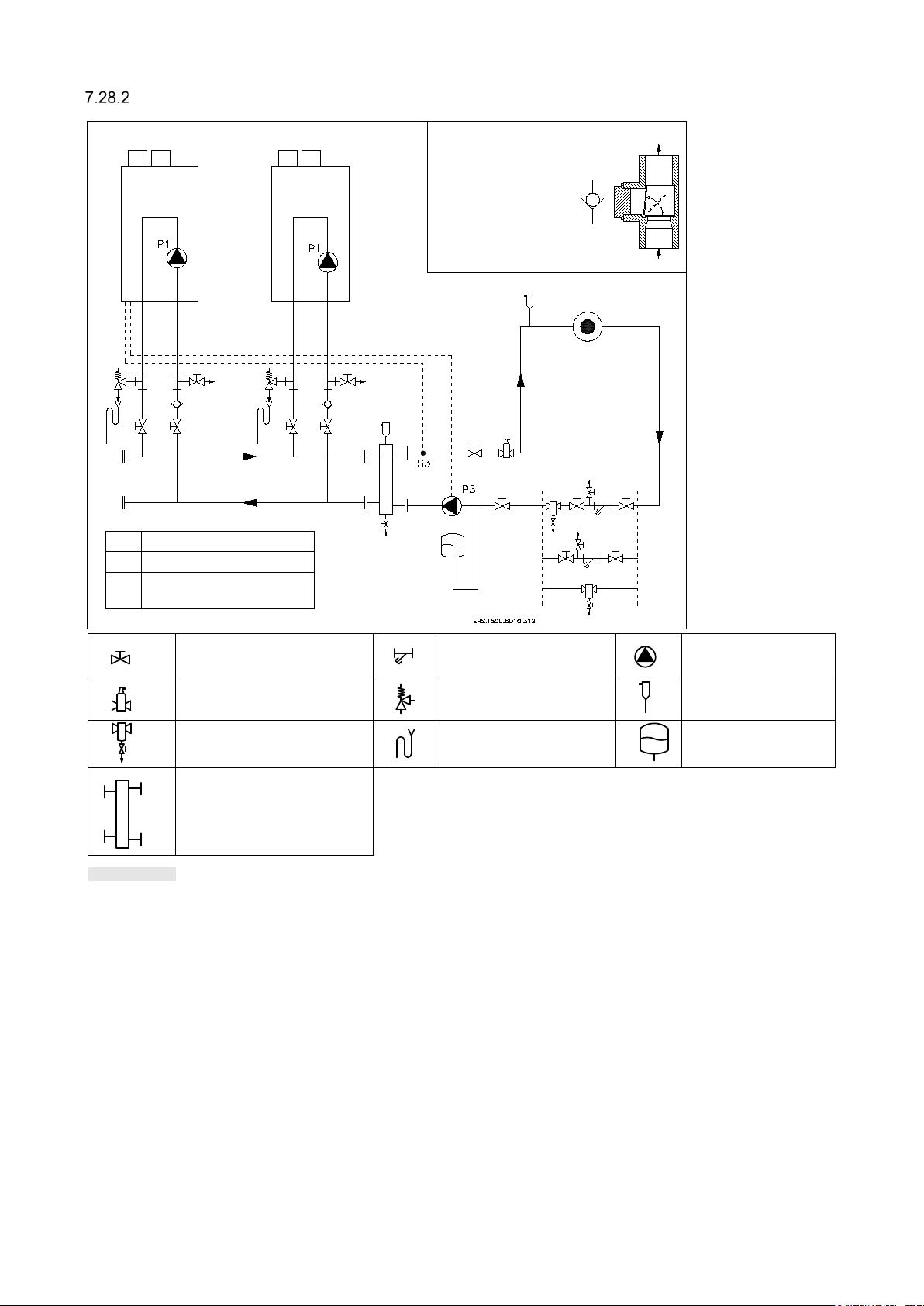
EXAMPLE OF A MULTIPLE BOILER HEATING CIRCUIT WITH LOW LOSS HEADER
Figure 7. 19
NON-RETURN
LOADED
P1
Boiler circulator
P3
System circulator
S3
Flow/ system
temperature sensor
HEATING ZONE
BOILER
BOILER
VALVE (low
resistance type)
NOT SPRING
valve strainer (water filter) circulator
ai
r separator
dirt separator
w loss header
lo
essure relief valve
pr
c
ondensate trap
omatic air vent
aut
ex
pansion vessel
46 E93.1901EN032 Installation and Service Manual SlantFin VGH-CH / CO
Page 47

8 CIRCULATOR CHARACTERISTICS
Figure 8.2
0
5
10
15
20
25
30
35
0 1 2 3 4 5 6 7 8
presuure drop [feet of head]
fl owr ate [gall ons/ m inut e]
Resistance graph VGH-80-CH and VGH-90-CO
heat exchanger circulator
0
5
10
15
20
25
30
35
40
0 1 2 3 4 5 6 7 8 9 10
presuure drop [feet of head]
fl owrate [ gall ons/minute]
Resistance graph VGH-100-CH
heat exchanger circulator
Pressure drop and flow graphs
BOILER RESISTANCE GRAPH VGH-80-CH / VGH-90-CO
BOILER RESI STANCE GRAPH VGH-100-CH
E93.1901EN032 Installation and Service Manual SlantFin VGH-CH / CO 47
Page 48

BOILER RESI STANCE GRAPH VGH-120-CH / VGH-150-CO
Figure 8.3
Figure 8.4
0
5
10
15
20
25
30
35
0 1 2 3 4 5 6 7 8 9 10 11 12
presuure drop [feet of head]
flowrat e [g allon s /minute]
Resistance graph VGH-120-CH and VGH-150-CO
heat exchanger circulator
0
10
20
30
40
50
60
0 1 2 3 4 5 6 7 8 9 10 11 12 13 14 15
presuure drop [feet of head]
flowrat e [g allon s /minute]
Resistance graph VGH-150-CH
heat exchanger circulator
BOILER RESI STANCE VGH-150-CH
48 E93.1901EN032 Installation and Service Manual SlantFin VGH-CH / CO
Page 49

BOILER RESI STANCE GRAPH VGH-180-CH / VGH-200-CO
Figure 8.5
Figure 8.6
0
5
10
15
20
25
30
35
0 1 2 3 4 5 6 7 8 9 10
presuure drop [feet of head]
fl ow r ate [ gal lon s / m i nu t e]
Internal circulation head curve
VGH-80-CH VGH-90-CO VGH-100-CH VGH-120-CH
VGH-150-CO VGH-150-CH VGH-180-CH VGH-200-CO
0
10
20
30
40
50
60
70
80
0 1 2 3 4 5 6 7 8 9 10 11 12 13 14 15 16 17 18
presuure drop [feet of head]
flowrat e [g allons /minute]
Resistance graph VGH-180-CH and VGH
-200-CO
heat exchanger circulator
GRAPH SHOWING THE AVAILABLE CIRCULATION PUMP HEAD
E93.1901EN032 Installation and Service Manual SlantFin VGH-CH / CO 49
Page 50

Minimum required circulator head.
Pressure drop boiler including
Slant/Fin plumbing kit
gal/min
m3/h
ft.W.C.
m.W.C.
VGH-80-CH / VGH-90-CO
7.60
1.73
27.3
8.3
VGH-100-CH
9.50
2.16
36.6
11.2
VGH-120-CH / VGH-150-CO
11.40
2.59
26.2
8.0
VGH-150-CH
VGH-180-CH / VGH-200-CO
17.10
3.88
69.4
21.2
Pressure drop boiler including
Slant/Fin plumbing kit
gal/min
m3/h
ft.
m.W.C.
VGH-80-CH / VGH-90-CO
3.8
0.86
6.83
2.1
VGH-100-CH
4.76
1.08
10.00
3.0
VGH-120-CH / VGH-150-CO
5.73
1.30
7.89
2.4
VGH-150-CH
7.14
1.62
12.16
3.8
VGH-180-CH / VGH-200-CO
Table 8.1
Table 8.2
Modulating circulator mode
Details
0
Disabled
No circulator modulation; the PWM duty cycle is always 0%
1
Delta temperature
modulation
Calculated duty cycle to create a delta temperature between the
T_Supply and T_Return sensor
2
Fixed 20% speed
Fixed duty cycle of 20%
3
Fixed 30% speed
Fixed duty cycle of 30%
4
Fixed 40% speed
Fixed duty cycle of 40%
5
Fixed 50% speed
Fixed duty cycle of 50%
6
Fixed 60% speed
Fixed duty cycle of 60%
7
Fixed 70% speed
Fixed duty cycle of 70%
8
Fixed 80% speed
Fixed duty cycle of 80%
9
Fixed 90% speed
Fixed duty cycle of 90%
10
Fixed 100% speed
Fixed duty cycle of 100%
Table 8.3
The design flow of the boiler should be be tween a del ta T of 20 °F and a delt a T of 40°F at high fire depending
boiler model and near bo il e r piping. Wh en ut il izi ng pr o per ly des igned primary secondary p ip ing t he int ern al b oil er
circulator is sized to prov ide the req uired flow for the giv en model. To c alculate the minimu m required c irculator
head and flow for a specific Delta T, take t he resistance of the boi ler and add the resista nce of the boiler loop
piping to make a g ood des ign. The Slant/F in plumbi ng kit has a m inimal pres sure dr op equiv alent t o less th an 1
foot of head. If a smaller delta T is desired than the built-in boiler circulator can provide an external circulator can
be added in the field external to the boiler in line with the boiler circulator on the return.
ΔT = 20 °F Minimum required flow
14.25 3.24 48.6 14.8
ΔT = 40 °F Minimum required flow
8.57 1.95 17.42 5.3
Modulating circulator for CH demand
The VGH boiler is provided with an internal circulator which can be switched on or off. The internal circulator is set
to speed sett ings 3 and thi s must never be changed. If the required f low is too lo w, an external circulator can be
installed by connecting the external circulator to the PWM circulator connection (see paragraph 10.3.1).
The control supports PWM modulation for the general circulator. Parameter 136 has to be set to modulating
(Factory set to on/off circulator) when using a modulating circulator. With this parameter the speed of the external
modulator must be set. The boiler circulator is modulated when there is a demand for CH.
During any other demand, the PWM circulator will run at a fixed speed s et by the Default Duty cycle parameter.
How the circulator is modulated is controlled with the Modulating_Pump_Mode setting.
Modulating circulator modes
There are several modu lating circulator m odes implement ed in the softw are. By selecting a diff erent modulat ing
circulator mode, the circulator behavior can be changed. The following modulating circulator modes are available.
50 E93.1901EN032 Installation and Service Manual SlantFin VGH-CH / CO
Page 51

Circulators: maximum electrical power
To all outputs following applies: maximum
circulators is maximum 8 A.
Picture 8.1
Picture 8.1
Picture 8.2
NOTICE
NOTICE
WARNING
FLAT
ROUND
RIGHT CONNECTOR AND CORD POSITIONING
General
• The inrush current of a conventional circulator is approximately 2½ x its nominal current.
• The maximum switch current of the PCB is 4 A.
• The total current of PCB and gas valve is approx. 0.5 A. All circ ulators and v alves for the boil er loop, DHW,
and the system that are connec ted to the boiler should not exceed 3.5 A. ( Combined power consumption of
internal circulator P1 a nd three way valve is 1 Amp) Use separ ate relays if high er currents ar e needed. The
fan is separately connected to the main supply and has a fuse of 3.15 A.
Boiler circulator (circulator P1)
This circulator is part of the appliance. The maximum c ombined current for the boiler loop circulator and any
additional circulators and valves should not exceed 2 A.
The internal boiler pump/circulator is electrically connected to connections
BE AWARE in the software the description “General Pump” is used for “Boiler Circulator”
DHW indirect tank circulator (circulator P2) – VGH-CH only
The circulator (circulator P2) is a DHW indirect tank circulator, meaning it is not part of the appliance. The maximum
combined current for the indirect tank circulator and any additional circulators and valves must not exceed 2 A.
Only Heating Only (CH) boilers can us e a D HW in dire c t tank circulator; Combi b o iler s never use a DHW in di rec t
tank circulator.
3-way valve – VGH-CH only
The combined nominal current of circulator P1 and the 3-way valve should not exceed 2 A.
System circulator (circulator P3)
The maximum combined current of circulator P3 and the other connected circulators should not exceed 2 A.
Warning (ECM circulators)
An ECM circulator cannot be powered directly by the boiler. Use a relay to isolate the boiler from the circulator.
6-7-PE Boiler Circulator (general pump)
current 2 A each output. Total output of all
Use an external relay if
nominal circulator currents
exceed 2 A.
currents combined maximum 3.5 A.
(Combined power consumption of internal
circulator P1 and three way valve is 1 Amp)
The inrush current of the 3-way valve and/or
CIRCULATOR POWER CORD POSITIONING
Be aware to connec t the p ower c ord r ight w hen r epla cing the c irc ulator or after d isconnec ting the p ower cor d for
service. See pictures below:
E93.1901EN032 Installation and Service Manual SlantFin VGH-CH / CO 51
Page 52
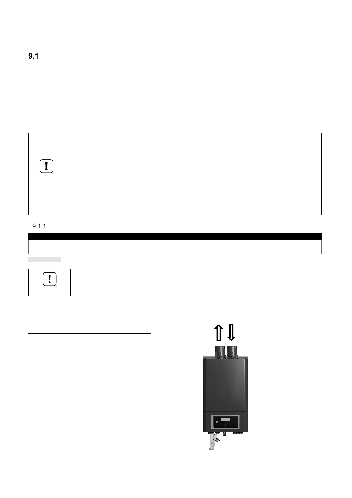
NOTICE
NOTICE
9 FLUE GAS AND AIR SU P PL Y SY STEM
When not installed
Boiler type
Intake Air and Connection
VGH-80-CH / VGH-90-CO / VGH-100-CH / VGH-120-CH VGH-150-CO /
VGH-150-CH / VGH-180-CH / VGH-200-CO
Table 9.1
AIR
INTAKE
VENT
General venting
The boiler has a positive pressure vent system.
The boiler is for either direct vent installation or for installation using indoor combustion air, category IV: appliance
with sealed combustion requiring certain venting systems. All combustion air is drawn from outdoors or indoor. All
products of combustion ar e vent ed directly o utdoors . The vent, and if applicab le air-intak e piping, must be piped
to the outdoors. Under no conditions should this appliance vent gases into a masonry chimney. The internal safety
system shuts down the boiler in case the temperature of the flue gases becomes too high, after which the appliance
will not run until manually restarted. Installations must comply with CSA B149.1 and local requ ir em ents .
The front cover creates an airtight enclosure making sure air is only supplied by the vent air intake . Therefore,
make sure the front cover always has been placed in its position during operation of the appliance.
• Install all horizontal vent components with a minimum angle of 3° downwards in the direction
of the boiler (roughly equal to 1/4 inch per foot or 5 cm per meter).
accordingly, it may res ult in c ondensat e buil ding-up in the v ent gas tube, ev entua lly c ausing
component failure.
• When using a wall terminal, there is the possible risk of ice buildup on surrounding
parts/structures, beca use the condensate will fr eeze. This risk must be t aken into account
during the design phase of the heating installation.
• Because the flue gases can have a low temperature, the boiler needs to have a high efficiency
approved stainless steel or plastic vent system. These materials, including the gaskets, must
be usable for positive pressure vent gas systems.
These parts must be certified for use at tempera tures of minimal 70°C / 158°F.
VENT SIZING
3"
Only 2" and 3" venting listed in this manual is permitted for use with the boiler.
Vent connector: us ed to provide a pass ageway for conveying c ombustion gases to the outside. A connector is
provided on the unit for final connection. Vent piping must be supported as per the National Building Code, Section
305, Table 305.4 or as local codes dictate.
Connections vent gas (vent) and air supply:
(FLUE GAS)
52 E93.1901EN032 Installation and Service Manual SlantFin VGH-CH / CO
Page 53

NOTICE
VENT AND AIR INLET RESISTANCE TABLE
Maximum Exhaust Length / Maximum Combustion Air Intake Length
VGH-80-CH
VGH-90-CO
VGH-100-CH
VGH-120-CH
VGH-150-CO
VGH-150-CH
VGH-180-CH
VGH-200-CO
2”
50 / 50
50 / 50
40 / 40
30 / 30
20 / 20
20 / 20
20 / 20
20 / 20
3”
150 / 150
150 / 150
150 / 150
150 / 150
100 / 100
100 / 100
100 / 100
100 / 100
Item\ size
Duravent
Polypro
2"
3"
1-ft Vent Pipe
1 1
1-ft Flex Pipe
(same diameter as rigid)
2
2
1-ft Flex Pipe
(upsized one diameter)
0.4
0.6
45 Elbow
3 3
90 Elbow
5 7
Tee 9
12
Reducer 3"-2"
(based on small diameter)
1.6
Reducer 4"-3"
(based on small diameter )
0.5
BOILER
TERMINAL
size
part #
Eq. feet
VGH-80-CH / VGH-90-CO
concentric roof:
2" vent
2PPS-VKL / 2PPS-VK-TCL
18 ft
concentric wall:
2" vent
2PPS-HKL
10 ft
concentric roof:
3" vent
3PPS-VKL / 3PPS-VK-TCL
25 ft
concentric wall:
3" vent
3PPS-HKL
11 ft
Items
Materials 1)
Venting System Standards
Warning
United States
Canada 3)
Flue piping and
CPVC Schedule 40
ANSI/ASTM F441
All venting
All Vent materials and
appliances in CAN/US
result in fire, serious
PVC Schedule 40
ANSI/ASTM D1785
Stainless Steel SS
UL-1738
Polypropylene PP
-
Air inlet piping
PVC - DWV
ANSI/ASTM D2265
Stainless Steel SS
UL-1738
Polypropylene PP
-
Pipe cement
PVC
ANSI/ASTM D2564
CPVC
ANSI/ASTM F493
Primers
PVC/CPVC
ANSI/ASTM F656
Notes:
Table 9.2
Table 9.3
Table 9.4
Table 9.5
Minimum and maximum allowed equivalent combined vent and air inlet length:
- Minimum venting length: two feet (2 ft) for all boilers.
- Maximum venting len gth: s ee table be low.
• For long lengths, check venting pipe and fittings for maximum allowable pressur e.
• This table should only be used for a single vent/air system for one boiler.
Do NOT use this table for common vent systems with cascaded boilers.
Pipe, elbows, tees - equivalent feet: for DuraVent PolyPro
Eq. feet
Terminals equivalent feet: for DuraVent PolyPro
VGH-100-CH / VGH-120-CH
VGH-150-CO / VGH-150-CH
VGH-180-CH / VGH-200-CO
Vent and air intake pipe material
Fittings
and Fittings 2)
material in
Canada must be
ULC S636
approved.
Air-Inlet materials being
installed on gas fired
must meet the Standards
listed in this Table.
Failure to comply could
injury or death.
1 PVC venting (exhaust and air-inlet) is not permitted within the Closet/alcove of a Closet/alcove installation.
2
The air-inlet does not require high temperature pipe material. Check applicable local codes for acceptable materials.
3 Use only vent gas material suitable for flue gas temperatures of 158⁰F (70⁰C) or higher.
E93.1901EN032 Installation and Service Manual SlantFin VGH-CH / CO 53
Page 54

Boiler
Fitting
2" Part #
3" Part #
Concentric Termination CPVC
197033
197107
Low profile Termination
196984
196985
FGV 45° Elbow CPVC
197169
197171
FGV 90° Elbow CPVC
197199
197201
Termination Vent Screen
196050
196051
• Never use aluminum containing vent pipes in these boilers.
Table 9.6
NOTICE
WARNING
WARNING
WARNING
• Do not store or use gasoline or oth er flammable vapors and liquids in t he vicinity of this or
any other appliance. Failure to follow instructions may result in serious injury or death.
• In Canada, the first piece of vent piping must be readily accessible for inspection.
• Covering non-metallic vent pipe and fittings with thermal insulation is prohibited.
• Failure to follow these instructions may result in property damage, personal injury or death.
APPROVED MANUFACTURERS
PVC/ CPVC venting:
* IPEX System 636
All models are designed to operate with flue gas temperature below 149°F / 65°C when set to
the max CH temperature of 194°F / 90°C enabling IPEX PVC appliance without restrictions.
Polypropylene venting:
* Duravent - PolyPro
* Centrotherm - InnoFlue
Stainless steel venting:
* Duravent - FasNSeal, FasNSeal Flex
* Security Chimneys - Secure seal SS/SSD/SSID
* HeatFab
Read the manual provided by the vent gas and air system supplier carefully.
PVC / CPVC
This product has been approved for use with the PVC/CPVC vent materials listed in this manual.
All terminations must comply with the listed options in this manual and be a single-wall vent offering.
For support and special connections required, see the manufacturer's instructions. All vent is to conform to
standard diameter and equivalent length requirements established.
Approved PVC/ CPVC vent pipe and fittings:
IPEX – System 636
VGH-80-CH / VGH-90-CO
VGH-100-CH / VGH-120-CH
VGH-150-CO / VGH-150-CH
VGH-180-CH / VGH-200-CO
• The use of cellular core PVC ( ASTM F891), cellular core CPVC, or Rade l® (polyphenol
sulfone) in the exhaust venting system is prohibited. Failure to follow these instructions may
result in property damage, personal injury or death.
• Insulation may not be us ed on PVC or CPVC or Polypropy len e vent in g m ater i als. The use
of insulation will caus e increased vent wall temp eratures, which could resu lt in vent pipe
failure.
• The PVC/ CPVC pipe and fittings must be cemented using an “All Purpose Cement” suitable
for PVC and CPVC pipe. U se only the vent mat erials, primer and cement sp ecifie d in this
manual to make th e vent connections. Failure to follow this warning could resu lt in fire,
personal injury, or death.
54 E93.1901EN032 Installation and Service Manual SlantFin VGH-CH / CO
Page 55

Supplier
Type
Duravent
PolyPro
Centrotherm
InnoFlue
Boiler
Termination
Color
2" Order
2" Stock
3" Order
3" Stock
CH
Twin Pipe Side Wall
black
2PPS-HTPL
810009685
3PPS-HTPL
810009713
Single Pipe Side Wall
stainless
2PPS-HSTL
810009684
3PPS-HSTL
810009712
Bird Screen
stainless
2PPS-BG
810004341
3PPS-BG
810004355
black
2PPS-VKL
810009692
3PPS-VKL
810009720
terra-cotta
2PPS-VK-TCL
810009693
3PPS-VK-TCL
810009721
concentric wall
white
2PPS-HKL
810009682
3PPS-HKL
810009710
PVC In Canada:
• In Canada, CPVC and PVC vent pipe, fittings and cement/ primer must be ULC-S636
minimum of a 1/4 inch per foot back to the boiler (to allow drainage of condensate).
Table 9.7
Table 9.8
WARNING
NOTICE
Safety authorities in some jurisdictions are not allowing PVC venting materials with
appliances of any kind, eve n if System 636 c ertif ied. Chec k with t he local safety ins pector
to verify compliance. Canadian installations must comply with the current CSA B149.1
Installation Code and local building codes.
certified.
• Use only cleaners, pr imers, and solvents that are approv ed for the materials which are
joined together.
• All PVC vent pipes must be glued, prop erly s upport ed, and th e exhaust m ust be p itc hed a
INSTRUCTIO NS F OR WORKI NG WITH CEMENTING PVC/ CPVC PIPE CONNECTIONS
1. Work from boiler to vent or air termination. Do not exceed lengths given in this manual for the air or vent piping.
2. Cut pipe to the required lengths and deburr the inside and outside of the pipe ends.
3. Chamfer outside of each pipe end to ensure even cement distribution when joining.
4. Clean all pipe ends and fittings using a clean dry rag (moisture will retard curing and dirt or grease will prevent
adhesion).
5. Dry fit vent or air piping to ensure prop er fit up befor e assemblin g any joint. Th e pipe must go a third t o twothirds into the fitting to ensure proper sealing after cement is applied.
6. Priming and Cementing:
a. Handle fittings and pipes carefully to prevent contamination of surfaces.
b. Apply a liberal even co at of primer to th e fitting socket and to the p ipe end to appr oximately 1/2" bey ond
the socket depth.
c. Apply a second primer coat to the fitting socket.
d. While primer is still wet, apply an even coat of approved cement to the pipe equal to the depth of the fitting
socket along with an even coat of approved cement to the fitting socket.
e. Apply a second coat of cement to the pipe.
f. While the cement is still wet, insert the pipe into the fitting, if possible, twist the pipe a 1/4 turn as you insert
it. Note: If voids are present, sufficient cement was not applied and joint could be defective.
g. Wipe excess cement from the joint removing ring or beads as it will needlessly soften the pipe.
Polypropylene
This product has been approved for use with polypropylene vent with the manufacturers listed.
All terminations must comply with listed options in this manual and be a single-wall vent offering.
For support and special connections required, see the manufacturer's instructions.
All vent is to conform to standard diameter and equivalent length requirements established.
Approved polypropylene vent pipe and fittings.
Approved polypropylene terminations:
Duravent – PolyPro
VGH-80-CH / VGH-90-CO
VGH-100-CH / VGH-120-CH
VGH-150-CO / VGH-150VGH-180-CH / VGH-200-CO
concentric roof
E93.1901EN032 Installation and Service Manual SlantFin VGH-CH / CO 55
Page 56
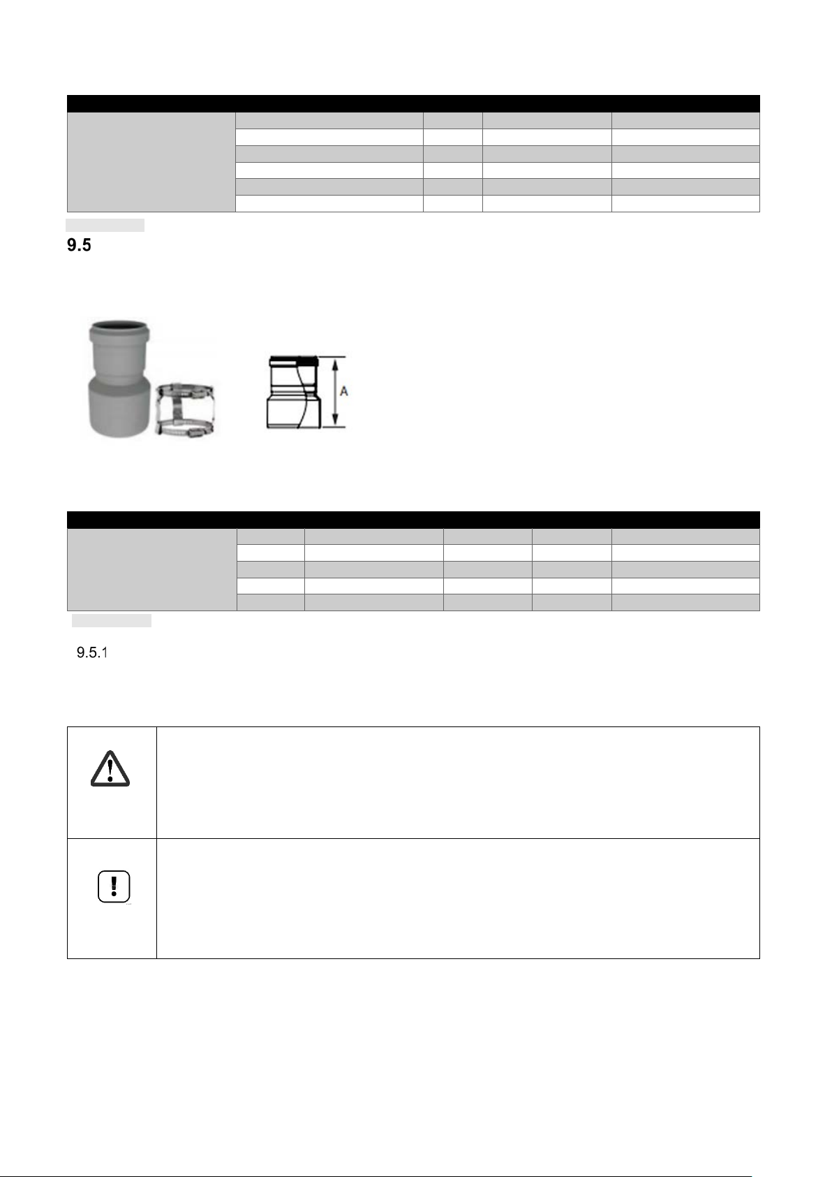
Centrotherm Innoflue
Boiler
Termination
Color
2" Order #
3" Order #
CH
3” Twin Pipe Side Wall
black
ISLPT0202
ISLPT0303
3" Termination Tee
black
ISTT0220
ISTT0320
3" Termination Pipe
black
ISEP02 or ISEP0239
ISEP03 or ISEP0339
3” Bird Screen
black
IASPP02
IASPP03
3" Concentric roof termination
ICRT2439
ICRT3539
3" Concentric wall termination
ICWT242
ICWT352
Boiler
Size
Order #
STOCK#
A
CH
3” - 2”
80 – 60 mm
3PPS-R2L
810009714
5” / 130mm
4” - 3”
100 – 80 mm
4PPS-R3L
810009746
5” / 130mm
5” - 4”
130 – 100 mm
5PPS-R4L
810009764
7
/
8
” / 193mm
6” - 5“
150 – 130 mm
6PPS-R5L
810009785
7
/
4
” / 197mm
8” - 6”
200 – 150 mm
8PPS-R6L
810009801
5
/
16
” / 150mm
Table 9.9
Table 9.10
DANGER
NOTICE
VGH-80-CH / VGH-90-CO
VGH-100-CH / VGH-120-CH
VGH-150-CO / VGH-150VGH-180-CH / VGH-200-CO
Reducer
If a reduction of the flue gas pipe is made from 3”to 2” a reducer is required to make it fit.
Use to transition the vent system to a smaller diameter. Includes 1 adapter Connector clamp.
Supplier: Duravent.
VGH-80-CH / VGH-90-CO
VGH-100-CH / VGH-120-CH
VGH-150-CO / VGH-150VGH-180-CH / VGH-200-CO
5
3
15
FLEXIBLE POLYPROPYLEN E
For use of flex pipe, it is recommended to have the vent material in 32°F or higher ambient space before bending
at installation. No bends should be made to greater than 45° and only installed in vertical or near vertical
installations.
• Insulation is prohibited from use on all types of plastic venting material: PVC, CPVC, and
Polypropylene.
• Use only the adapters and vent system listed.
• DO NOT mix vent systems of different types or manufacturers.
• Failure to comply could result in severe personal injury, death, or substantial property
damage.
56 E93.1901EN032 Installation and Service Manual SlantFin VGH-CH / CO
• The installer must use a specific vent starter adapter at the flue collar connection.
• The adapter is supplied by the vent manufacturer to adapt to its vent system.
• Installations must comply with applicable national, state, and local codes.
• For Canadian installation, polypropylene vent must be listed as a ULC-S636 approved
system. Installation o f a poly propylen e vent sys tem mu st adher e to the v ent ma nufac turer’s
installation instructions supplied with the vent system.
Page 57

Stainless steel vent
Supplier
Type
Duravent
FasNSeal, FasNSeal Flex
Security Chimneys
Secure Seal SS/S SD/ SSID
Heat Fab
Saf-T EZ Seal
Duravent
Security Chimneys
HeatFab
FasNSeal
Secure Seal
Saf-T EZ Seal/ EZ 316
Boiler
Termination
Termination
Termination
FSBS3 (bird screen wall)
part.nr. 300325
SS3STAU
(rain cap roof)
5390CI
(rain cap)
Table 9.11
Table 9.12
NOTICE
WARNING
This product has been approved for use with stainless steel using the manufacturers listed.
Approved stainless steel vent pipe and fittings.
*Use of FasNSeal Flex smooth inner wall vent is to be used in vertical or near vertical sections only, taking
precaution to ensure no s agging occurs of the vent sys tem. Connect to the FasNSea l rigid vent using speci ally
designed adapters and sealing method, see manufacturer’s instructions.
Use only the materials, vent systems, and terminations listed.
Approved Stainless Steel Terminations.
DO NOT mix vent systems of different types or manufacturers. Failure to comply could result
in severe personal injury, death, or substantial property damage.
• The installer must use a specific vent starter adapter at the flue collar connection,
supplied by the vent manufacturer to adapt to its vent system.
• Installations must comply with applicable national, state, and local codes. Stainless steel
vent systems must be listed as a UL-1738 approved system for the United States and a
ULC-S636 approved system for Canada.
• Installation of a stainless-steel vent system must adhere to the stainless-steel vent
manufacturer’s installation instructions supplied with the vent system.
VGH-80-CH / VGH-90-CO
VGH-100-CH / VGH-120-CH
VGH-150-CO / VGH-150-CH
VGH-180-CH / VGH-200-CO
part.nr. 300236
FSRC3 (rain cap roof)
(screen termination)
SS3RC
(horizontal termination)
5300CI
Sealed Combustion Air supply
When an air supply pipe is connected from the o utside of the building to the boiler , the boiler will operate as a
sealed combustion boiler.
The air supply duct can be made of PVC, PP or Stainless steel
COMBUSTION AIR QUALITY
Combustion air mus t be free of co ntaminants. Do not inst all the intake for the combust ion air venti ng in an area
which contains corrosive or other contaminants as outlined in section 9.8.1, especially Table 9.11 and Table 9.12.
AIR SUPPLY THROUGH HUMID AREAS
When the combustion a ir pipe will ru n through an ar ea with high humidity (for examp le: greenhouses ), a double
walled supply pipe or an in sulated duct mus t be used to prev ent the pos sibl e con densation on the outside of the
pipe. It is not pos si ble to insulate the in terna l air p ipes of th e bo iler an d theref ore condens atio n at the interna l air
canals must be prevented.
When the intake combustion air is terminated vertically through a roof an approved termination designed to prevent
water from entering into the combustion air pipe must be used.
E93.1901EN032 Installation and Service Manual SlantFin VGH-CH / CO 57
Page 58

AIR INTAKE/VENT CONNECTIONS
Figure
WARNING
NOTICE
DANGER
Air intake
connector
The combustion air intake connector (see Figure 9.1) is used to provide
combustion air directly to the unit from outdoors. A connector is provided
on the unit for final connection. Combustion air piping must be supported
as per g uidelines l isted in the N ational Mecha nical Co de, Section 30 5,
Table 305.4 or as local codes dictate.
9.1
AIR INLET PIPE MATERIALS
The air inlet pipe(s) must be sealed. Choose acceptable combustion air inlet pipe materials from the following list:
• PVC, CPVC or PP
• Flexible propylene air intake
• Galvanized steel vent pipe with joints and seams sealed as specified in this section.
• Type “B” double-wall vent with joints and seams sealed as specified in this section.
• AL29-4C, stainless steel material to be sealed to specification of its manufacturer.
Sealing of Type “B” double-wall vent material or galvanized vent pipe material used for air inlet piping on a wall or
vertical rooftop Combustion Air Supply System:
a) Seal all joints and seams of the air inlet pipe using either Aluminum Foil Duct Tape meeting UL Standard 723
or 181A-P or a high-quality UL Listed silicone sealant such as those manufactured by Dow Corning or General
Electric.
b) Do not install seams of vent pipe on the bottom of horizontal runs.
c) Secure all joints with a minimum of three (3) sheet metal screws or pop rivets. Apply Aluminum Foil Duct Tape
or silicone sealant to all screws or rivets installed in the vent pipe.
d) Ensure that the air inlet pipes are properly supported.
The PVC or CPVC air inlet pipe must be cleaned and sealed with the pipe manufacturer’s recommended solvents
and standard commercial pipe cement for the material used.
Proper sealing of the air inlet pipe ensures that combustion air will be free of contaminants and supplied in proper
volume. Follow the polypropylene or flexible polypropylene manufacturer’s instructions when using polypropylene
material as an inlet pipe.
When a wall or vertical rooftop combustion air supply system is disconnected for any reason, the air inlet pipe
must be resealed to ensure that combustion air will be free of contaminants and supplied in proper volume.
Using air intake materials other than those specified can result in personal injury, death or
property damage.
The use of double-wall vent or insulated material for the combustion air inlet pipe is
recommended in cold climates to prevent the condensation of airborne moisture in the incoming
combustion air.
58 E93.1901EN032 Installation and Service Manual SlantFin VGH-CH / CO
Failure to properly seal all joints and seams as required in the air inlet piping may result in flue
gas recirculation, s pillage of flue products and c arbon monoxide emissions caus ing severe
personal injury or death.
Page 59

Room air
When utilizing the single pipe method, provisions for combustion and ventilation air must be in
Appliances and Equipment.
Figure 9.2
WARNING
The boiler may be ins talled w ith a s in gle pi pe car r ying the f lue pr oduc ts to the outside while us i ng co mbus t io n ai r
from the room. In this case it is very important to provide adequate combustion air: as an example in an unconfined
space a VGH-200-CO boiler needs ap pr oxim ate ly 1 0,0 00 ft3 i.e. a room with dimensions 36' x 36' x 8'. Fai lur e to
provide adequate combustion air can result in boiler failure, fire, explosion, severe personal injuries or death.
Other considerations and conditions:
• The boiler must be installed in a positive or neutral pressure room. If kitchen hoods or exhaust fans are present,
makeup air must be provided.
• The boiler must be installed with an appropriate room air bird screen
• There will be a noticeable increase in noise level from the air inlet, compared with an air line from the outside.
• Using room a ir makes the unit vulnerable to comb ustion air contamination from with in the building. Please
review section 9.8.1 “Air contamination” in this manual, to ensure proper operation.
accordance with: Local, state an d nationa l codes , laws, ordna nces and r egulatio ns 9.3 Air for
Combustion and Ventilation, of the latest edition of the National Fuel Gas Code, ANSI
Depending on the local situation, one of the following methods (from ANSI Z223.1/NFPA 54) applies:
The distance of the top of t he upp er opening to the to p of th e equipm ent room a nd from t he bottom of th e lower
opening to the bottom of the room shall be within 12 inch.
Now check if the two rooms together have enough volume to conform to method 1.
If coupling to another room does not bring enough air, it will be necessary to provide outside air:
Z223.1/NFPA 54.
In Canada, the latest edition of CSA Standard B149 Installation Code for Gas Burning
1. If the boiler is installed in a room with a volume of more than 50
3
per 1,000 Btu/hr of the aggregate input rating of all
ft
combustion appliances in the room, the infiltration rate of t he
room will provide adequate combustion air. No additional
measures have to be take n. However, if the r oom is situate d in
a building with a known infiltration rate smaller than 0.40 ACH,
the evaluation shall be with the KAIR method in ANSI Z223.1.
2. If th e bo iler is inst alled in a room wit h a volume of less than 50
3
per 1,000 Btu/hr of the aggregate input rating of all
ft
combustion applia nces in the room, the room m ust have two
separate air openings to an adjacent room. If this room is on the
same floor, each op ening must have a free area of mini mum 1
2
per 1,000 Btu/hr . If this room is on a diff erent floor, the
inch
minimum free area is 2 inch
2
area is 100 inch
per air opening. The minimum dimension of an
2
per 1,000 Btu/hr . Minimum free
opening is 3 inch. If louvers are designed to cover the openings,
the free area of these louvers should be considered. If these are
not documented, count 2 5% for wooden louvers and 75 % for
metal louvers.
E93.1901EN032 Installation and Service Manual SlantFin VGH-CH / CO 59
Page 60

Figure 9.3
Figure 9.4
Furnace
Furnace
Furnace
Water
heater
Water
heater
Water
heater
If combustion air is provided from the outside by means of
vertical ducts like above, the free size of each opening
2
must be minimal 1 inch
per 4,000 Btu/hr of the aggregate
input rating of all combustion appliances in the room.
If the outside air is provided by means of hor izo nta l d uc ts ,
2
the free size of each opening mus t be m inima l 1 inc h
per
2,000 Btu/hr of the aggregate input rating of all combustion
appliances in the room.
60 E93.1901EN032 Installation and Service Manual SlantFin VGH-CH / CO
Page 61
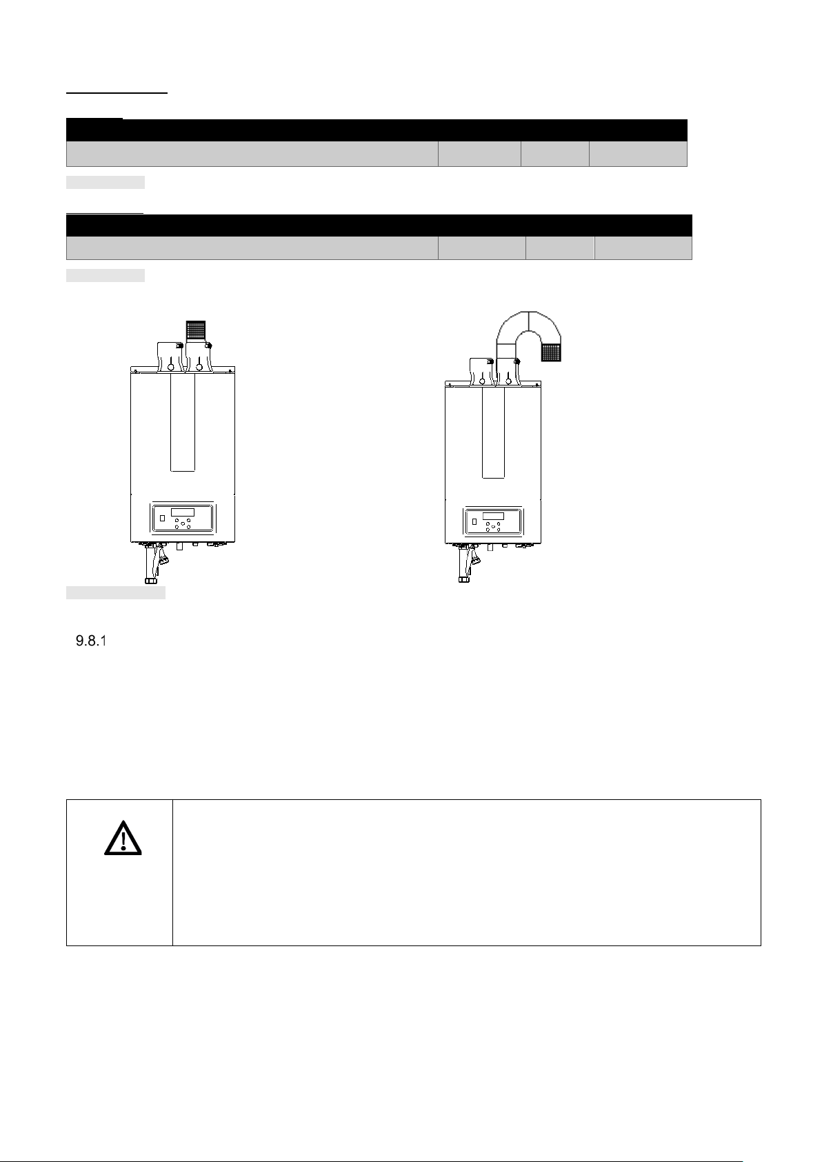
Indoor air parts:
Boiler
Termination
Color
3" Stock
Boiler
Termination
Color
3" Order
Table 9.13
Table 9.14
Figure 9.5
WARNING
Boiler is IP20 apply-
bird screen
only
Boiler is IPX4D
screen with two
elbows and if
ary, a short
Room air
Duravent
All VGH Boilers
Centrotherm
All VGH Boilers
Bird Screen stainless 810004355
Bird Screen black IASPP03
ing a
applying a bird
necess
straight pipe.
examples
AIR CONTAMINAT ION
Pool and laundry products and common household and hobby products often contain fluorine or chlorine
compounds. When these chemicals pass through the boiler, they can form strong acids. The acid can eat through
the boiler wall, causing serious damage and presenting a possible threat of flue gas spillage or boiler water leakage
into the building.
Please read the information given in the list below, with contaminants and areas likely to contain them. If
contaminating chemicals will be present near the location of the boiler combustion air inlet, have your installer pipe
the boiler combustion air and vent to another location, as per this manual.
• The boiler should never be located in areas such as a l aundry r oom or poo l faci lity. These
areas will always contain hazardous contaminants.
• To prevent the potential of severe personal injury or death, check for areas and products
listed in the list with contaminants below, before installing the boiler or air inlet piping.
• If contaminants are found, you MUST:
• remove contaminants permanently
or
• relocate air inlet and vent terminations to other areas.
E93.1901EN032 Installation and Service Manual SlantFin VGH-CH / CO 61
Page 62

Corrosive Contaminants and Sources
Products to avoid:
• Spray cans containing chloro/fluorocarbons
Areas likely to have
• Dry cleaning/laundry areas and establishments
Table 9.11
Table 9.12
• Permanent wave solutions
• Chlorinated waxes/cleaners
• Chlorine-based swimming pool chemicals
• Calcium chloride used for thawing
• Sodium chloride used for water softening
• Refrigerant leaks
• Paint or varnish removers
• Hydrochloric acid/muriat ic ac id
• Cements and glues
• Antistatic fabric softeners used in clothes dryers
• Chlorine-type bleaches, detergents, and cleaning solvents found in
• Adhesives used to fasten building products and other similar products
household laundry rooms
contaminants:
• Swimming pools
• Metal fabrication plants
• Beauty shops
• Refrigeration repair shops
• Photo processing plants
• Auto body shops
• Plastic manufacturing plants
• Furniture refinishing areas and establishments
• New building construction
• Remodeling areas
• Garages with workshops.
62 E93.1901EN032 Installation and Service Manual SlantFin VGH-CH / CO
Page 63

CAUTION
• The boiler must be vented and supplied with combustion and ventilation air as described in
or death.
• This appliance requires a special venting system. Use only approved stainless steel, PVC,
damage.
Installation must comply with local requirements and with the National Fuel Gas Code,
system.
WARNING
DANGER
NOTICE
Proper vent installation and type of gas vent or vent connector
For boilers for connect ion to gas vents or chimneys, v ent installations must be in accordance with “Ventin g of
Equipment,” of the N ational Fuel Gas Code, ANSI Z223.1/NFPA 54, or “ Venting Systems and Air Supply for
Appliances,” of the Natural Gas and Propane Installation Code, CAN/CSA B149.1, or applicable provisions of the
local building codes.
Vent connectors serving appliances vented by natural draft must not be connected into any portion of mechanical
draft systems operating under positive pressure.
Covering non-metallic vent pipe and fittings with thermal insulation is prohibited.
For Category IV venting, the venting system must be installed in accordance with the boiler manufacturer's
installation instructions.
Non-combustible supports must be placed a minimum of every 4 feet on horizontal portions of the venting system
to prevent sagging of th e venting system. Th e supports must al low the boiler to be free fr om strain and prev ent
the weight of the v enting system from resting on the boiler. The supports must allow for a ¼” (21 mm) slope
upwards from the boi ler to t he term inati on. This wil l prev ent the ac cumulat ion of condensat e and allow it to dr ain
back towards the boiler and reduce the risk of icing at the termination.
Install vent and combustion air piping
this section.
• Ensure the vent and air piping and the combustion air supply comply with these instructions
regarding vent sy stem, air sy stem, and co mbustion ai r quality. See als o section 9.13.2 of
this manual.
• Inspect finished vent and air piping thoroughly to ensure all are airtight and comply with the
instructions provided and with all requirements of applicable codes.
• Failure to provide a properly installed vent and air system will cause severe personal injury
CPVC or polypropylene p ipe and fitt ings listed f or vent pipe and fittings. Failur e to comply
could result in severe personal injury, death, or substantial property damage.
The boiler vent and air piping can be i nstalled through th e roof or through a wall. Follow the procedures in this
manual for the method chosen. Refer to the information in this manual to determine acceptable vent and air piping
length.
You should use any of the vent/air piping methods covered in this manual. Do not attempt to install the boiler using
any other means.
You must also insta ll air piping from outside to the boiler air intake adapter, unless following the "Room Air"
instructions in paragraph 9.8 of this manual. The resulting installation is direct vent (sealed combustion).
• DO NOT mix components from different systems. The vent system could fail, causing
leakage of flue products into the living space. Mixing of venting materials will void the
warranty and certification of the appliance.
• For closet and alcove installations, CPVC, polypropylene or stainless-steel material MUST
BE used in th e closet/alcove structure. F ailure to follow this warning c ould result in fire,
personal injury, or death.
• Do not c onnect any other appliance to the vent p ipe or multiple boilers to a c ommon v ent
pipe. Failure to comply could result in severe personal injury, death, or substantial property
Improper installation of venting systems may result injury or death.
•
ANSI Z223.1/NFPA 54 for U.S. installations or CSA B149.1 for Canadian installations.
• Follow the instructions in this manual when removing a boiler from an existing vent
E93.1901EN032 Installation and Service Manual SlantFin VGH-CH / CO 63
Page 64

Requirements for installation in Canada
relocate the boiler and air intake to an area free from all possible contaminants.
Two pipes wall
See paragraph 9.13 for more details.
Two pipes vertical
See paragraph 9.14 for more details.
Figure 9.6
Figure 9.7
WARNING
1. Installations must be made with a vent pipe system certified to ULC-S636.
2. The first three (3) f eet of p lastic vent pipe fr om th e ap plianc e fl ue out let must be readi ly acc essib le for v isu al
inspection.
3. The components of the c ertified vent system must not be interchanged with othe r vent systems or unlisted
pipe/ fittings. For concent ric vent installatio ns, the inner vent tub e must be certified v ent material in order t o
comply with this requirement.
• When utilizin g th e s i ngl e p i pe m etho d, provisions for c ombustion and ventilati on a ir mus t
be in accordance with Air for Combustion and Ventilation, of the latest edition of the
National Fuel Gas Code, ANSI Z223.1/NFPA 54, in Canada, t he latest edition of CGA
Standard B149 Installation Code for Gas Burning Appliances and Equipment, or
applicable provisions of the local building codes.
• The inlet for combustion air can never be located inside a room storing chemicals or
contaminants as listed in section 9.8.1. Avoid installing the boiler in any area with
possible contaminants.
• If contaminants are found, you MUST:
• remove contaminants permanently
or
•
Direct venting options
64 E93.1901EN032 Installation and Service Manual SlantFin VGH-CH / CO
Page 65

Concentric wall - two pipe to boiler
See paragraph 9.13 for more details.
Concentric wall - concentric to boiler
See paragraph 9.13 for more details.
Concentric vertical - two pip e to boiler
See paragraph 9.14 for more details.
Concentric vertical - concentric to boiler
See paragraph 9.14 for more details.
Figure
Figure 9.8
Figure
Figure 9.9
9.10
9.11
E93.1901EN032 Installation and Service Manual SlantFin VGH-CH / CO 65
Page 66

Different pressure zone
Open, Air supply from room,
See paragraph 9.14 for more details.
Air inlet
Flue outlet
Vented area
Figure
Boiler is IPX4D applying a
bird screen with two
Boiler is IP20
applying a bird
Figure
9.12
See paragraph 9.13 for more details.
elbows and if necessary, a
short straight pipe.
screen only
9.13
66 E93.1901EN032 Installation and Service Manual SlantFin VGH-CH / CO
Page 67

WARNING
CAUTION
WARNING
NOTICE
Wall (Horizontal) direct venting
VENT/AIR TERMINATION - WALL
• Follow instr uctions below when determining vent location to avoid possibility of s evere
personal injury, death, or substantial property damage.
DETERMINE LOCATION
Locate the exhaust vent/air intake terminations using the following guidelines:
1. The total length of piping for exhaust vent or air intake must not exceed the limits given in the "General Venting"
section, in paragraph 9.1 of this manual.
2. You must consider the surroundings when terminating the exhaust vent and air intake:
a. Position the vent termination where exhaust gases will not damage nearby shrubs, plants or air conditioning
equipment or be objectionable.
b. The flue product s w ill for m a notice able plum e as they condens e i n co ld a ir. Avoi d are as w here t he plum e
could obstruct window views.
c. Prevailing winds could cause freezing of condensate and water/ice buildup where flue products impinge on
building surfaces or plants.
d. Avoid hazard of accidental contact of flue products with people or pets.
e. Do not locat e th e ter m ina tions wher e w ind edd ies c ou ld af fect p erfor m anc e or c au s e rec irc ulat ion, s uch as
inside building corners , near adjacent b uildings or sur faces, window w ells, stairwells , alcoves, cour tyards,
or other recessed areas.
f. Do not terminate above any door or window. Condensate can freeze, causing ice formations.
g. Locate or guard vent to prevent condensate damage to exterior finishes.
3. When us ing two pipe ter minations the air intake piping must terminate in a down-turned elbow as s hown in
Figure 9.15 and 9.16. This arrangement avoids recirculation of flue products into the combustion air stream.
4. The exh aust piping must t erminate horizontally in a section of str aight pipe or an el bow pointed outw ard or
away from the air inlet, as shown in Figure 9.15 and 9.16.
• A gas ven t extending through an exterior wall must not terminate adjacent t o a wall or
below building extensions such as eaves, parapets, balconies, or decks.
• Failure to c omply could result in severe per sonal injury, death, or substant ial property
damage.
Maintain 12” of clearance above the highest anticipated snow level or grade, whichever is
greater. Please refer to your local codes for the snow level in your area.
Do not exceed the maximum lengths of the outside vent piping stated in this manual.
Excessive length expos e d t o the outside cou ld c ause freezing of c o nde ns ate i n t h e v en t pip e,
resulting in potential boiler shutdow n and possibly a blocked flue.
PVC/CPVC or PP is acceptable air intake pipe material.
E93.1901EN032 Installation and Service Manual SlantFin VGH-CH / CO 67
Page 68
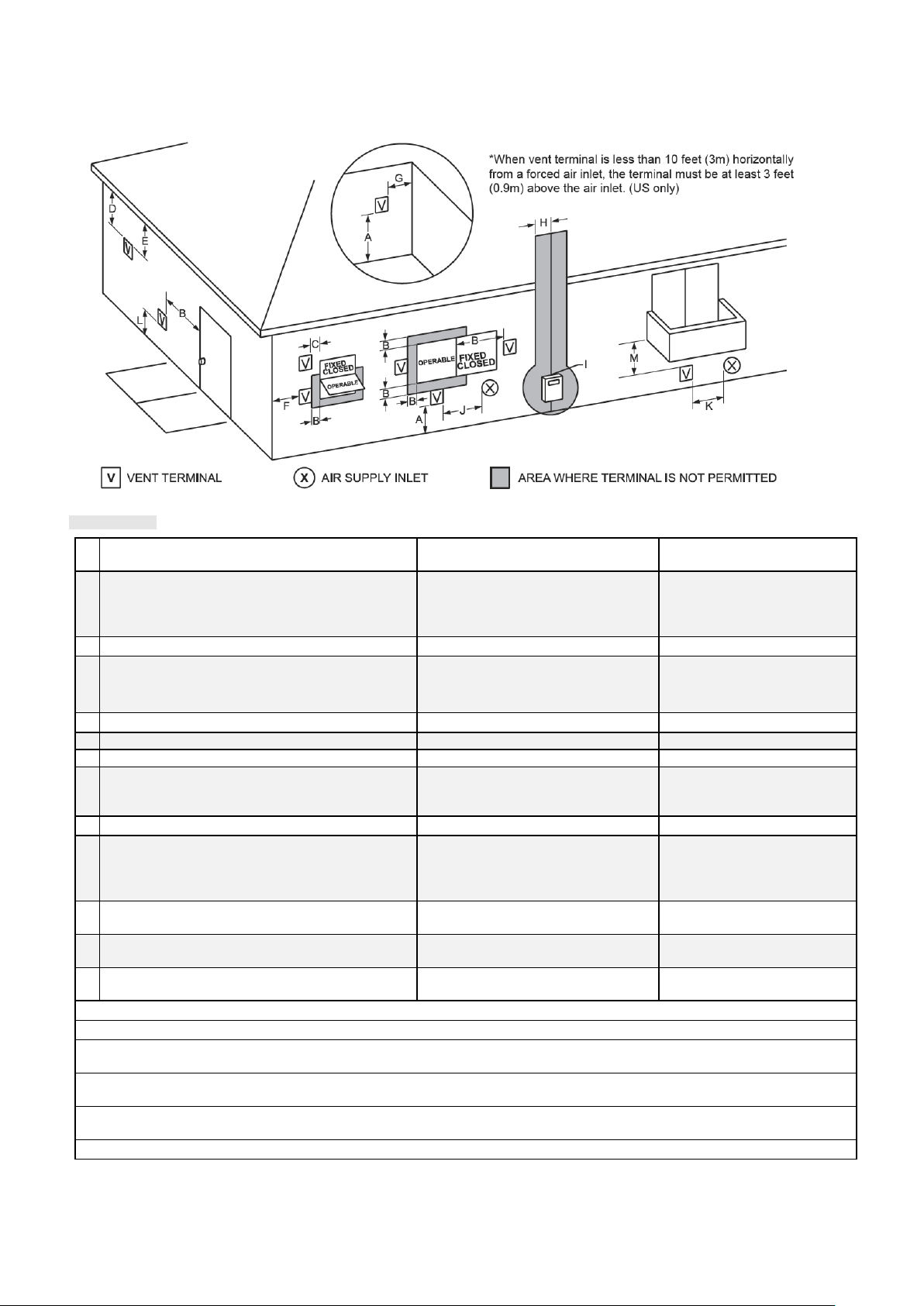
5. Maintain clearances as stated in this manual. Also maintain the following:
Figure 9.14
A
Clearance above grade, veranda, porch, deck, or
balcony
12" (30 cm)
see note 3
12" (30 cm)
see note 3
B
Clearance to window or door that may be opened
Direct vent only: 12" (30 cm)
Direct vent: 4 ft (1.2 m) below or
cm) above
opening
36 inches (91 cm)
C
Clearance to permanently closed window
see note 4
see note 5
D
Vertical clearance to ventilated soffit located
see note 4
see note 5
E
Clearance to unventilated soffit
see note 4
see note 5
F
Clearance to outside corner
see note 4
see note 5
G
Clearance to inside corner
see note 4
see note 5
H
Clearance to each side of center line extended
see note 4
3 ft (91 cm) within a height of
meter/regulator assembly
I
Clearance to service regulator vent outlet
see note 4
3 ft (91 cm)
J
Clearance to nonmechanical air supply inlet to
Direct vent only: 12” (30 cm);
Direct vent: 4 ft (1.2 m) below or
to side of opening; 1 ft (30 cm) above
opening
3 ft (91 cm)
K
Clearance to a mechanical air supply inlet
3 ft (91 cm) above if within 10 ft (3 m)
horizontally
6 ft (1.83 m)
L
Clearance above paved sidewalk or paved
driveway located on public property
Vent termination not allowed.
7 ft (2.1 m)
M
Clearance under veranda, porch, deck, or
balcony
see note 4
12" (30 cm) see note 6
note 1: In accordance with the current ANSI Z223.1 / NFPA 54 National Fuel Gas Code
note 2: In accordance with the current CAN/CSA-B149.1 Installation Codes
note 3: Maintain 12” of clearance above the highest anticipated snow level or grade or, whichever is greater. Please refer to
your local codes for the snow level in your area
note 4: For clearances not specified in ANSI Z223.1 / NFPA 54, clearance is in accordance with local installation codes and
the requirements of the gas supplier.
note 5: For clearances not specified in CAN/CSA-B149, clearance is in accordance with local installation codes and the
requirements of the gas supplier
note 6: Permitted only if veranda, porch, deck, or balcony is fully open on a minimum of two sides beneath the floor.
above the terminal within a horizontal distance of
2 ft (61 cm) from the center line of the terminal
above meter/regulator assemb ly
building or the combustion air inlet to any other
appliance
Nonto side of opening; 1 ft (30
15 ft above the
Non-
6. Locate terminations so they are not likely to be damaged by foreign objects, such as stones or balls, or
subject to buildup of leaves or sediment.
68 E93.1901EN032 Installation and Service Manual SlantFin VGH-CH / CO
Page 69

Alternate two pipe sidewall termination of air intake
Figure 9.15
Figure 9-16
Figure 9.17
12" Min.
16" Max.
Two pipe sidewall termination of air intake and
exhaust vent.
and exhaust vent
Two pipe sidewall termination assembly.
E93.1901EN032 Installation and Service Manual SlantFin VGH-CH / CO 69
Page 70

Multiple vent/air terminations
Figure 9.3
Figure 9.18
Figure 9.19
WARNING
1. When terminating multiple boilers, terminate each vent/air connection as described in this manual.
All vent pipes and a ir inlets must termi nate at the same height to avoid possibility of severe
personal injury, death, or substantial property damage.
2. Place wa ll penetrat ions to obtain mi nimum clear ance of 12 inches (305 mm) between the ins ide edge o f the
exhaust vent and the inside edge of the air intake elbow, as shown in figure 9.18 for U.S. installations.
For Canadian installations, provide clearances required by CSA B149.1 Installation Code.
3. The air inlet of the boiler is part of a direct vent connection. It is not classified as a forced air intake with regard
to spacing from adjacent boiler vents.
Two pipe multiple boilers vent terminations.
Note: Keep air intake at min. 12" above grade or snow
line. Provide vent and air intake with bird screen.
Concentric Sidewall termination installation:
Wall termination – concentric vent
Description and usage: concentric combustion air and
exhaust vent pipe termination. Both combustion air and
exhaust vent pipes must at tach to the termin ation k it. T he
termination kit must terminate outside the structure and
must be installed as shown. The required combustion vent
pipe materials are listed in Table 9.5 of this manual.
Concentric sidewall termination clearances:
Sidewall termination installation
- Determine the best location for the termination kit
- Reference paragraph 9.13.2 of this manual for general
termination considerations.
70 E93.1901EN032 Installation and Service Manual SlantFin VGH-CH / CO
Page 71
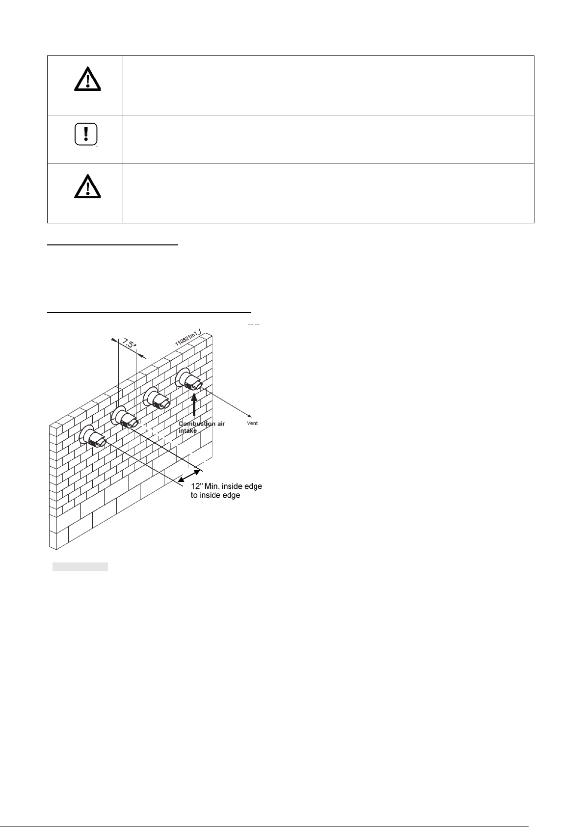
Figure 9.20
WARNING
NOTICE
CAUTION
Do not operate th e appl iance wit h the ra in cap removed from t he conc entric ter minations or
else recirculation of combustion products may occur. Water may also collect inside the larger
combustion air pip e and flow to the burner enclosure. Failure to follow t his warning could
result in product damage or improper operation, personal injury, or death.
Multi venting wall terminations
When two (2) or more direct vent appliances are vented near each other, each appliance must be individually
vented (see Figure 9.20). NEVER common vent or breach vent this appliance. When two (2) or more direct vent
appliances are vented near each other, two (2) vent terminations should be installed as shown in Figure 9.20. It
is important that vent terminations be made as shown to avoid recirculation of flue gases.
Concentric sidewall multiple boilers termination.
Ensure termination location clearance dimensions are as shown in the appropriate figures
DO NOT use field-supplied couplings to extend concentric terminations. Airflow restriction
will occur and may cause intermittent operation.
Note: keep the terminals horizontally in the same line and at min. 12” above grade or snow line.
E93.1901EN032 Installation and Service Manual SlantFin VGH-CH / CO 71
Page 72

Roof (vertical) direct venting
Figure 9.21
WARNING
WARNING
VENT/AIR TERMINATION – VERTICAL
DET ERMINE LOCATION
Locate the vent/air terminations using the following guidelines:
Follow instructions below when determining vent location to avoid possibility of severe
personal injury, death or substantial property damage.
1. The total length of piping for vent or air must not exceed the limits given in the section 9.1 of this manual.
2. Prepare the vent termination and the air intake termination elbow (see Figure 9.21) by inserting bird screens.
3. The exhaust vent must terminate at least 3 feet above the highest place in which the exhaust vent penetrates
the roof and at least 2 feet above any part of a building within 10 horizontal feet.
4. The air intake pipin g must t ermin ate in a down-turned 180° direction utilizing two elbows, see Figure 9.21.
5. The exhaust piping must terminate in a vertical coupling as shown in . The top of the coupling must be at least
1 foot above the air intake . Whe n the v e nt termination uses a rain c ap, maintain at least 36" ( 91 4 mm) ab ove
the air inlet. The air intake pipe and exhaust v ent pipe can be locate d in any desired position on the roof,
provided that the exhaust vent termination is at least 1 foot above the air intake.
6. Maintain the required dimensions of the finished termination piping as shown in Figure 9.21.
7. Do not extend exp osed vent pipe o utside of build ing more than s hown in this do cument. Condens ate could
freeze and block the vent pipe.
Rooftop exhaust vent and air intake inlet terminations must terminate in the same pressure
zone.
Two pipes vertical termination of air and vent.
8. Locate terminations so they are not likely to be damaged by foreign objects, such as stones or balls, or subject
72 E93.1901EN032 Installation and Service Manual SlantFin VGH-CH / CO
to buildup of leaves or sediment.
Page 73

Multiple vent/air terminations
Figure 9.22
Figure 9.23
WARNING
12“MIN
1. When terminating multiple boilers, terminate each vent/air connection as described in this manual (Figure 9.22).
Terminate all exhaust vent pipes at the same height and all air intake pipes at the same height
to avoid recirculatio n of f lue produc ts and t he possib ility of s evere pers onal i njury, de ath, or
substantial property damage.
2. Place roof penetrations to obtain minimum clearance of 12 inches (305 mm) between outside edge of air intake
an exhaust vent of anot her boiler for U. S. installations (see Figure 9.22). For C anadian install ations, provide
clearances required by CSA B149.1 Installation Code.
Vertical terminations with multiple boilers.
Note: keep terminals at min. 12" above grade or snow line. Provide exhaust vent and air intake with bird screen.
Alternate vertical terminations with multiple boilers.
N
ote: keep the terminals at min. 12" above grade or snow line. Provide vent and air intake with bird screen.
E93.1901EN032 Installation and Service Manual SlantFin VGH-CH / CO 73
Page 74

Concentric Vertical Termination.
Do not operate the a pplian ce with th e rain cap removed from the concentric terminati ons or
injury, or death.
• Do not allow ins ulation or other mater ials to accumulate i nside the pipe assemb ly when
(305 mm) in U.S.A. or 18 inches (457 mm) in Canada) as shown in Figure 9.24.
Figure 9.24
WARNING
NOTICE
CAUTION
Minimum clearance
roof or snow level.
Figure
above snow level
(18” for Canada)
Maximum 24” above
Do not install U-Bend or elbow on concentric termination
9.25
else recirculation of combustion products may occur.
Multi venting vertical terminations
When two (2) or mor e direct vent applianc es are vented near eac h other, each applia nce must be individually
vented (see Figure 9.26). NEVER com mon v ent or br each v ent this appl iance. When two (2) or mor e direc t v ent
appliances are vented near each other, two (2) vent terminations should be installed as shown in Figure 9.26. It is
important that vent terminations be installed as shown to avoid recirculation of flue gases.
Water may also collect inside the larger combustion air pipe and flow to the burner enclosure.
Failure to follow this warning could result in product damage or improper operation, personal
installing through the hole.
• Ensure termi nation he ight is abov e the roof surface or anticipat ed snow l evel (12 inches
DO NOT use field-supplied couplings to extend concentric terminations. Airflow restriction will
occur.
74 E93.1901EN032 Installation and Service Manual SlantFin VGH-CH / CO
Page 75

Concentric vent and combustion air vertical termination multiple boilers.
Figure 9.26
Common venting
The boilers fr om th e VGH series have n o internal flue gas check valve and need to be c alcu lated for an ex ternal
flue gas check valve system or a separa ted flue sy stem. If separated f lue sy stems c annot be app lied, ask a flue
gas supplier to calculate a common vent system utilizing external flue gas check valves..
Existing Common Venting Guidelines
Do not common vent the VGH-boiler with the vent pipe of any other boiler or appliance. However, when an existing
boiler is removed from an existing c ommon v enting s ystem, th e commo n venti ng sys tem is lik ely to be too lar ge
for proper venting o f the appliances rema ining connected to it. At the time of removal of an existing boiler , the
following steps must be followed with each appliance remaining connected to the common venting system placed
in operation, while the other appliances remaining connected to the common venting system are not in operation.
1) Seal any unused openings in the common venting system.
2) Visually inspect the venting system for proper size and horizontal pitch and determine there is no blockage or
restriction, leakage, corrosion and other deficiencies which could cause an unsafe condition.
3) I nsofar as is practical, close al l building doors and window s and all doors between th e space in which the
appliances remaining connected to the common venting system are located and other spaces of the building.
Turn on clothes dryers and any appliance not connected to the common venting system. Turn on any exhaust
fans, such as range hoods and bathroom exhausts, so they will operate at maximum speed. Do not operate a
summer exhaust fan. Close fireplace dampers.
4) Put into operation the appliance being inspected. Follow the lighting instructions. Adjust thermostat so
appliance will operate continuously.
5) Test for spillage at the draft hood r e lief op en ing a fter 5 minutes of main burn er ope rat ion. U se t he f la me of a
match or candle, or smoke from a cigarette, cigar, or pipe.
6) After it has been determined that each appliance remaining connected to the common venting system properly
vents when tested as outlin ed above, retur n doors, win dows, exhaus t fans, firep lace damp ers and any oth er
gas-burning appliance to their previous condition of use.
7) Any improper operation of the common venting system must be corrected so the installation conforms with the
National Fuel Gas Code, ANSI Z223.1/NFPA 54 and/or CAN/CSA B149.1, Natural Gas and Propane
Installation Code. When resizing any portion of the common venting system, the common venting system must
be resized to approac h the minimum size as deter mined using the appropriat e tables in Chapter 13 in the
National Fuel Gas Code, ANSI Z223.1/NFPA 54 and/or CAN/CSA B149.1, Natural Gas and Propane
Installation Codes.
E93.1901EN032 Installation and Service Manual SlantFin VGH-CH / CO 75
Page 76

10 ELECTRICAL INSTALLATION
Figure 10.1
Figure 10.2
HIGH VOLTAGE CONNECTIONS
NOTICE
NOTICE
LOW VOLTAGE CONNECTIONS
General
• For operation, the boiler needs a power supply of 120 VAC / 60Hz.
• The boiler main supply connection is polarity sensitive.
• The wiring for the connections can be entered at the bottom of the boiler t hrough the w iring knockouts.
•
• Electrical wiring must be installed according to all applicable standards and regulations.
In the USA, electrical installation must comply with NFPA 70, National Electrical Code – latest edition, and
with any other national, state, provincial or local codes and regulations.
• Wiring the boiler must only be done by a qualified installer or, where required, a licensed electrician skilled
in working on electrical installati ons and according to all applicab le standards.
• It is not allowed to change the internal wiring fitted by the manufacturer.
• A spare fuse is mounted on the casing of the burner controller.
Connection mains supply
• We advise to use a flexible cable between the cabinet entry (at the bottom) and the connection terminal.
• The ground wire has to be longer than the Line voltage (Hot) and neutral wire.
• The power supply cable must be secured by a strain-relief at the bottom of the boiler casing.
• In case of a flexible cable: use crimp ferrules on each wire end for the terminal connections.
• On the high voltage terminal, connect to numbers: 8 = Line voltage (Hot); 9 = Neutral; PE = Ground.
Electri cal co nn ect io n s VGH-CH/CO boilers
• Before starting to work on the boiler, it must be switched off and the power
supply to the boiler must be disconnected and the gas valve closed.
In Canada, electrical installation must comply with CSA C22.1, Canadian Electrical Code part 1
– latest edition, and with any other state or local codes and regulations.
Read: “circulator”
if the word “pump”
is used
High power ignitor
A separate connector for an external igniter is located on the wiring
harness, near the boiler controller and labelled "High power ignitor".
The "external ignition transformer" can be ordered, see paragraph
5.1.
This accessory is provided with detailed mo unt ing ins tr uc tions .
76 E93.1901EN032 Installation and Service Manual SlantFin VGH-CH / CO
Page 77

EXPLANATION OF THE LOW VOLTAGE CONNECTIONS VGH-CH BOILERS
1-2
OUTDOOR SENSOR
3-4
SYSTEM SENSOR
If a low loss header is used , this sens or measures the flow t emperat ure at the system side. The sensor must
PARAMETER: boiler parameter 122, see paragraph 10.6.
5-6
DHW SENSOR
7-8-9
MODBUS
10-11
AL-BUS DEPENDING
Cascade connections for the dependent boilers, must be parallel linked together.
12-13
ON/OFF STAT OR MODULATING HEATING CIRCUIT
OPTION 1: An ON/OFF thermostat can be connected.
PARAMETER: boiler parameter 124, see paragraph 10.6
14-15
0-10 VDC CONTROL SIGNAL
These terminals are used for an external 0-10 VDC control input signal.
NOTICE: Terminal 14 [+] (positive) and terminal 15 [-] (negative).
16-17-18
DHW - FLOW SWITCH
For DHW_Mode 3 a flow switch can be c onn ec ted . If a w a ter f low is pr es e nt, th e s witc h c l os es, and the DHW
PARAMETER: boiler parameter 117, see paragraph 10.6
19-20
PWM – CIRCULATOR CONTROL
These connections are us ed to control the boiler circulator. The PWM signal determ ines the speed of the
Parameter 136 has to be set to modulating (factory set to on/off circulator) when using a modulating circulator.
21-22
AL-BUS MANAGING / CASCADE
23-24
LWCO EXTERNAL
27-28
SAFETY SWITCH 2
Table 10.1
If an outdoor temperat ure s ensor is connec ted, th e boil er will c ontrol t he supply w ater te mpera ture by usin g a
calculated setting based on outdoor reset curve, which is related to the outdoor temperature.
be mounted on the supply pipe or in a sensor well at the system side, close to the low loss header.
NOTICE: This sensor (see Figure 7.17 and 7.19) must be used when boilers are cas caded with the i nternal
cascade manager.
When an indirect hot water tank is installed, the DHW mode must be set to 1 or 2. When the DHW mode is set
to 1, a sensor can be connected. This sensor must be mounted in a well in the tank. The boiler will now modulate
towards the hot water setpoint. When the DHW mode is set to 2, an aquastat can be connected. When the set
temperature is reached, the aquastat will switch off and the boiler will stop serving hot water.
Connections for a BMS.
7 = ground, 8 = A, 9 = B (A detailed manual is available at your supplier on request)
NOTICE: link all connections 10 to 10 and all connections 11 to 11, do not mix these.
Link connections 10 of the dependent boilers to 20 of the managing boiler, and connections 11 of the dependent
boilers to 21 of the managing boiler.
If these terminals are bridged, the set/programmed flow temperature of the boiler will be used.
OPTION 2: An modulating control ler can be connec ted to these termina ls. The boiler software w ill detect an d
use this modulating s igna l auto matically.
circulator is started. The temperature of the DHW is set with DHW_Setpoint.
circulator, when there is a heat demand. 18 = Signal (PWM input), 19 = Ground (Signal ref.)
Cascade connection for the managing boiler.
Link connection 21 of the managing boiler to connections 10 of the depending boilers, and connection 22 of the
managing boiler to connections 11 of the depending boilers.
To be used for an extra external Low Water Cut Off. The boiler goes into a lockout when this contact opens
25-26 SAFETY SWITCH 1
To be used for an extra external safety switch. The boiler goes into a lockout when this contact opens
To be used for an extra external safety switch. The boiler goes into a lockout when this contact opens
E93.1901EN032 Installation and Service Manual SlantFin VGH-CH / CO 77
Page 78

EXP L ANAT ION OF THE HIGH VOLTAGE CONNECTIONS VGH-CH BOILERS
1-2-3-PE
3 WAY VALVE (TWV)
4-5-PE
SYSTEM PUMP / DHW CIRCULATOR / CH CIRCULATOR
Connections for th e power supply of a ce ntral heating system circulator P3, see paragraph 8.5.for detailed
4 = Line voltage (Hot) wire; 5 = Neutral wire; PE = Ground
6-7-PE
BOILER CIRCULATOR / GENERAL PUMP
Connections for the power supply of the internal boiler circulator. (P1, see paragraph 8.5 for detailed
specifications).
8-9-PE-PE
MAINS SUPPLY
10-11
ALARM RELAY
A semiconductor alarm out put.
PARAMETER: boiler parameter 127, see paragraph 10.6.
X1-X2-X3
HIGH POWER IGNITER (external igniter)
A separate connector for an external igniter is located on the wiring harness, near the boiler controller and
PARAMETER: boiler parameter 126, see paragraph 10.6.
Table 10.2
NOTICE
NOTICE
This connection is internally connected to the 3-way valve in the appliance
electrical specifications. PARAMETER: boiler parameter 125, see paragraph 10.6
When using DHW mo de 1 or 2 and t he co il in t he tank has a high pr ess ure drop an ex tra DHW c ircula tor ca n
be added. The pump can be connected to terminals 4-5-PE. Therefore the parameter on output 1 needs to be
changed from 4 (System circulator) to 3 (DHW circulator) (see paragraph 11.9.2).
The power supply connection of the unit. 8 = Line voltage wire; 9 = Neutral wire, PE = Ground wire
This is a triac output w ith an active voltage of 120 VAC, it can only handle resist ive loads between 5 and 50
Watt. E.g. an incandescent bulb of 10-50 Watt can be connected. This alarm will be activated 60 seconds after
an error has occurred.
There are a few exceptions:
- Alarm output will not be activated for a servic e warning;
- Alarm output will not be activated for warning 202 (Appliance selection).
10 = Line voltage (Hot) wire; 11 = Neutral wire
labelled "High power ignitor". This is a connection for an external ignition transformer. Instead of the internal
igniter, an external igniter can be connected. Available as an accessory, see paragraph
X1 = Neutral wire; X2 = not used; X3 = Line voltage (Hot) wire.
To all outputs following applies: maximum current 2 A each output.
(Combined power consumption of internal circulator P1 and three way valve is 1 Amp)
The inrush current of the 3-way valve and/or circulators is maximum 8 A.
The internal boiler pump/circulator is electrically connected to connections
BE AWARE in the software the description “General Pump” is used for “Boiler Circulator”
Total output of all currents combined maximum 3.5 A.
6-7-PE Boiler Circulator (general pump)
5.1.
78 E93.1901EN032 Installation and Service Manual SlantFin VGH-CH / CO
Page 79

EXPLANATION OF THE LOW VOLTAGE CONNECTIONS VGH-CO BOILERS
1-2
OUTDOOR SENSOR
3-4
SYSTEM SENSOR
If a low loss header is used, this sensor measures t he flow tem perature at the syst em side. Th e sensor must
PARAMETER: boiler parameter 122, see paragraph 10.6.
5-6
DHW SENSOR
7-8-9
MODBUS
10-11
AL-BUS DEPENDING
boilers to 22 of the managing boiler.
12-13
ON/OFF STAT OR MODULATING HEATING CIRCUIT
OPTION 1: An ON/OFF thermostat can be connected.
PARAMETER: boiler parameter 124, see paragraph 10.6
14-15
0-10 VDC CONTROL SIGNAL
These terminals are used for an external 0-10 VDC control input signal.
NOTICE: Terminal 14 [+] (positive) and terminal 15 [-] (negative).
16-17-18
DHW - FLOW SWITCH
boilers.
19-20
PWM – CIRCULATOR CONTROL
These connections are us ed to control the boiler circulator. The PWM signal determines the speed of the
Parameter 136 has to be set to modulating (factory set to on/off circulator) when using a modulating circulator.
21-22
AL-BUS MANAGING / CASCADE
23-24
LWCO EXTERN
27-28
SAFETY SWITCH 2
Table 10.3
If an outdoor temperat ure s ensor is connec ted, th e boil er will c ontrol t he su pply w ater te mperatur e by using a
calculated setting based on outdoor reset curve, which is related to the outdoor temperature.
be mounted on the supply pipe or in a sensor well at the system side, close to the low loss header.
NOTICE: This sensor ( see Figure 7.17 and 7.19) must be used wh en boilers are cas caded with the intern al
cascade manager.
If combi boiler this connection is connected to the internal sensor on the plate heat exchanger,
for heating only boiler this connection can be used to connect a sensor for an indirect hot water tank.
Connections for a BMS
7 = ground, 8 = A, 9 = B (A detailed manual is available at your supplier on request)
Cascade connections for the dependent boilers, must be parallel linked together.
NOTICE: link all connections 10 to 10 and all connections 11 to 11, do not mix these.
Link connections 10 of the dependent boilers to 21 of the managing boiler, and connections 11 of the dependent
If these terminals are bridged, the set/programmed flow temperature of the boiler will be used.
OPTION 2: An Modulating control ler can be connec ted to thes e termi nals. The b oiler software w ill detec t and
use this Modulating s igna l auto matically.
This connection is internally connected to the flow sensor in a combi boiler and not used on heating only
circulator, when there is a heat demand. 18 = Signal (PWM input ), 19 = Ground (Signal ref.)
Cascade connection for the managing boiler.
Link connection 21 of the managing boiler to connections 10 of the depending boilers, and connection 22 of the
managing boiler to connections 11 of the depending boilers.
To be used for an extra external Low Water Cut Off. The boiler goes into a lockout when this contact opens
25-26 SAFETY SWITCH 1
To be used for an extra external safety switch. The boiler goes into a lockout when this contact opens
To be used for an extra external safety switch. The boiler goes into a lockout when this contact opens
E93.1901EN032 Installation and Service Manual SlantFin VGH-CH / CO 79
Page 80

EXP L ANAT ION OF THE HIGH VOLTAGE CONNECTIONS VGH-CO BOILERS
1-2-3-PE
3 WAY VALVE (TWV)
4-5-PE
SYSTEM PUMP
Connections for th e power supply of a central heating sy stem circulator P3, see paragraph 8.5. for detailed
4 = Line voltage (Hot) wire; 5 = Neutral wire; PE = Ground
6-7-PE
BOILER CIRCULATOR / GENERAL PUMP
Connections for the power supply of the internal boiler circulator. (P1, see paragraph 8.5 for detailed
specifications).
8-9-PE-PE
MAINS SUPPLY
10-11
ALARM RELAY
A semiconductor alarm output.
PARAMETER: boiler parameter 127, see paragraph 10.6.
X1-X2-X3
HIGH POWER IGNITER (external igniter)
A separate connector for an external igniter is located on the wiring harness, near the boiler controller and
PARAMETER: boiler parameter 126, see paragraph 10.6.
To all outputs following applies: maximum current 2 A each output.
The inrush current of the 3-way valve and/or circulators is maximum 8 A.
Table 10.4
NOTICE
NOTICE
This connection is internally connected to the 3-way valve in the appliance
electrical specifications. PARAMETER: boiler parameter 125, see paragraph 10.6
The power supply connection of the unit. 8 = Line voltage wire; 9 = Neutral wire, PE = Ground wire
This is a triac output with an ac tive voltage of 120 VAC , it can only handle resist ive loads between 5 an d 50
Watt. E.g. an incandesc ent bulb of 10-50 Watt can be added t o this. This al arm will be activ ated 60 second s
after an error has occurred.
There are a few exceptions:
- Alarm output will not be activated for a service war n i ng;
- Alarm output will not be activated for warning 202 (Appliance selection).
10 = Line voltage (Hot) wire; 11 = Neutral wire
labelled "High power ignitor". This is a connection for an external ignition transformer. Instead of the internal
igniter, an external igniter can be connected. Available as an accessory, see paragraph
X1 = Neutral wire; X2 = Ionization; X3 = Line voltage (Hot) wire.
Total output of all currents combined maximum 3.5 A.
(Combined power consumption of internal circulator P1 and three way valve is 1 Amp)
The internal boiler pump/circulator is electrically connected to connections
6-7-PE Boiler Circulator (general pump)
BE AWARE in the software the description “General Pump” is used for “Boiler Circulator”
5.1.
80 E93.1901EN032 Installation and Service Manual SlantFin VGH-CH / CO
Page 81

LADDER/LOGIC DIAGRAM VGH-CH/CO BOILERS
Figure 10.3
E93.1901EN032 Installation and Service Manual SlantFin VGH-CH / CO 81
Page 82

ELECTRICAL SCHEMATIC VGH-CH BOILERS
Figure 10.4
82 E93.1901EN032 Installation and Service Manual SlantFin VGH-CH / CO
Page 83

Figure 10.5
E93.1901EN032 Installation and Service Manual SlantFin VGH-CH / CO 83
Page 84

ELECTRICAL SCHEMATIC VGH-CO BOILERS
Figure 10.6
84 E93.1901EN032 Installation and Service Manual SlantFin VGH-CH / CO
Page 85
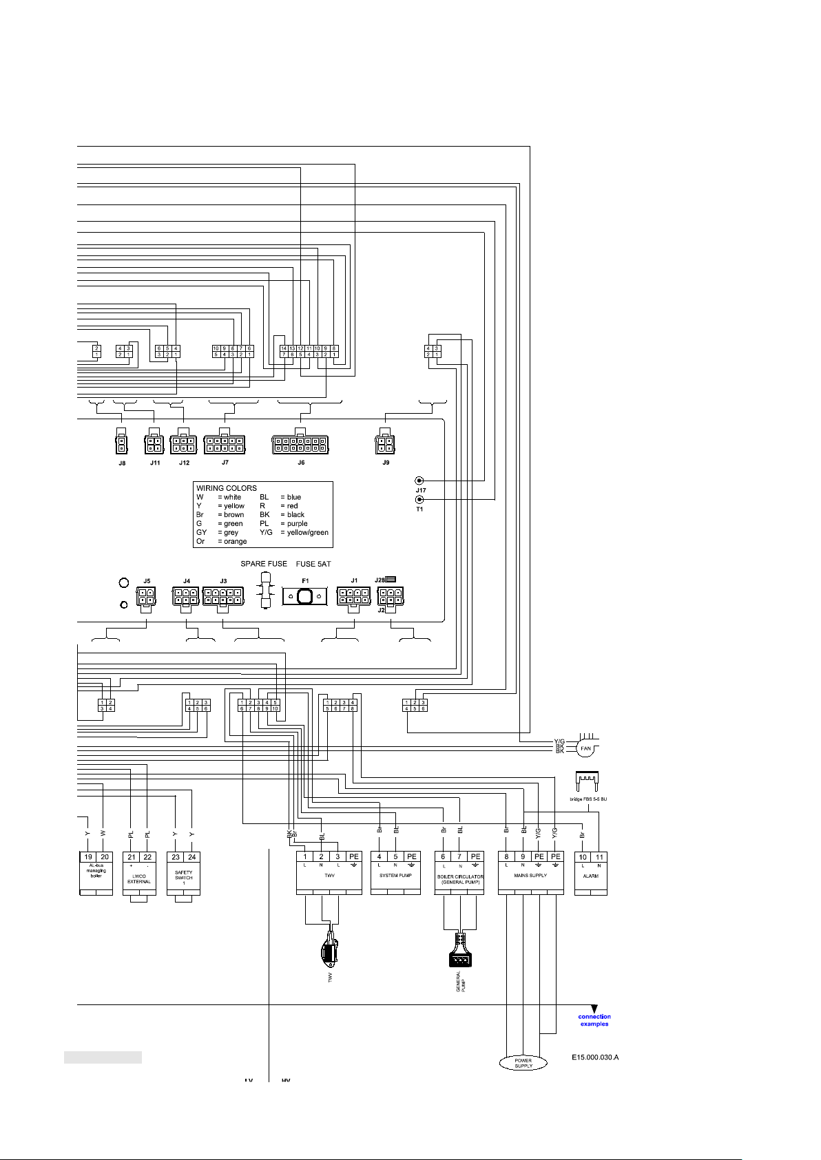
Figure 10.7
E93.1901EN032 Installation and Service Manual SlantFin VGH-CH / CO 85
Page 86
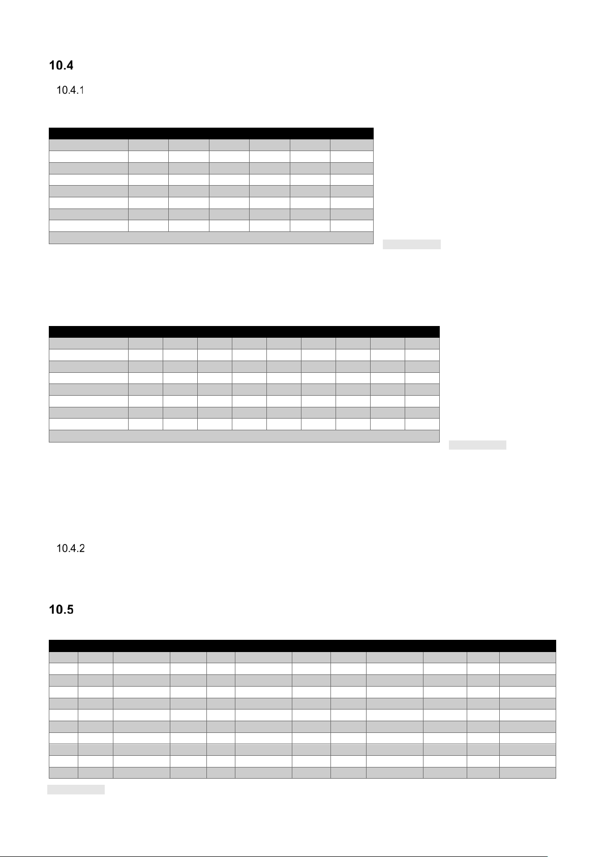
Sensor ava ilab il i t y
Temperature
Resistance
Temperature
Resistance
Temperature
Resistance
Temperature
Resistance
°C
°F
(Ω)
°C
°F
(Ω)
°C
°F
(Ω)
°C
°F
(Ω)
-30
-22
175203
20
68
12488
70
158
1753
120
248
387
-25
-13
129289
25
77
10000
75
167
1481
125
257
339
-20
-4
96360
30
86
8059
80
176
1256
130
266
298
-15 5 72502
35
95
6535
85
185
1070
135
275
262
-10
14
55047
40
104
5330
90
194
915
140
284
232
-5
23
42158
45
113
4372
95
203
786
145
293
206
0
32
32555
50
122
3605
100
212
677
150
302
183
5
41
25339
55
131
2989
105
221
586
155
311
163
10
50
19873
60
140
2490
110
230
508
160
320
145
15
59
15699
65
149
2084
115
239
443
165
329
130
CH Mode
0 1 2 3 4 5
T_Supply
M M M M M
M
T_Return
O O O O O
O
T_DHW O O O O O O
T_Outdoor
--- M M O O
0-10 Volt
O O O O M
M
Water Flow DHW
O O O O O
---
RT Swit ch
M M M M M
---
M = Mandatory, O = Optional, --- = Disabled.
Table 10.5
DHW Mode
0 1 2 3 4 5
6 N.A.
7 N.A.
8 N.A.
T_Supply
O M M O M O M M M
T_Return
O O O O M O --- O M
T_DHW
--- M --- M M M M
--- M T_Outdoor
O O O O O O ---
--- O 0-10 Volt
O O O O O O O O O
Water Flow DHW
O O O O O M O M M
RT Swit ch
O O M O O O O O O
M = Mandatory, O = Optional, --- = Disabled, N.A. = Not Available.
Table 10.6
Table 10.7
SENS O R AV AIL ABILITY VGH-CH BOILERS
The following table shows the sensor availability for all CH and DHW control modes. Sensors not mentioned in
the table are optionally available for other functions
CH mode 0 – Central Heating demand with thermostat control
CH mode 1 – CH with an outdoor temperature reset and thermostat control
CH mode 2 – Central Heating with full outdoor temperature reset
CH mode 3 – Central Heating with permanent heat demand
CH mode 4 – Central Heating with analog input control of setpoint
CH mode 5 – Central Heating with analog input control of power output
DHW mode 0 – No Domestic Hot Water
DHW mode 1 – Storage with sensor
DHW mode 2 – Storage with thermostat
DHW mode 3 – Instantaneous water heating with plate heat exchanger, flow switch and DHW-out sensor
DHW mode 4 – Instantaneous water heating with plate heat exchanger and DHW-out sensor
DHW mode 5 – Instantaneous water heating with plate heat ex c ha nger, DHW-out sensor and rotary switch
DHW mode 6 to 8 N.A.
SENS O R AV AIL ABILITY VGH-CO BOILERS
If the installed appliance is a VGH-CO combi boiler, the available sensors for the various CH modes are identical
to the data presented in Table 10.5. A VGH-combi boiler always has its DHW mode set to 5. Other DHW modes
are not available for Combi-boilers. Table 10.6 shows the available sensors for this mode.
NTC sensor curve
All NTC sensors are according to this characteristic: NTC 10K@25°C B3977k
86 E93.1901EN032 Installation and Service Manual SlantFin VGH-CH / CO
Page 87

Programmable in- and outputs
Default
setting CH
Default
setting CO
117
Prog. Input 2.
2 1 DHW flow switch/sensor
LV 16-17-18
122
Prog. Input 7.
3 3 Cascade sensor
LV 3-4
124
Prog. Input RT.
1 1 Room thermostat on
LV 12-13
125
Prog. Output 1.
4 4 System pump
HV 4-PE-5
126
Prog. Output 2.
9 9 Ext. Igniter
separate connector
127
Prog. Output 3.
6
6
Alarm semi-conductor output
HV 10-11
128
Prog. Output 4.
18
N.A.
3-way Valve DHW
HV 1-2-3-PE
parameter
Display:
INPUTS:
re-mark
parameter
Display:
OUTPUTS:
re-mark
(117)
Prog. Input 2.
0 Disabled
(127)
Prog. Output 3.
0 Disabled
1 DHW flow sensor
CO
1 Module pump
2 DHW flow switch
CH
2 CH pump
3 CH flow sensor
not used
3 DHW pump
4 CH flow switch
not used
4 System pump
5 Cascade pump
6 Alarm relay
CH/CO 2)
para-
meter
Display:
INPUTS:
re-mark
7 Filling valve
(122)
Prog. Input 7.
0 Disabled
8 LPG tank
1 T_Flue_2 sensor
not used
9 Ext. Igniter
2 T_Flue_2 with blocked flue
not used
10 Air damper
3 Cascade sensor
CH/CO
(128)
Prog. Output 4.
0 Disabled
4 Blocked Flue switch
not used
1 Module pump
5 CH Sensor
not used
2 CH pump
(124)
Prog. Input RT.
0 Room thermostat off
3 DHW pump
1 Room thermostat on
CH/CO
4 System pump
Display:
OUTPUTS:
5 Cascade pump
(125)
Prog. Output 1.
0 Disabled
6 Alarm relay
1 Module pump
7 Filling valve
2 CH pump
8 LPG tank
3 DHW pump
9 Ext. Igniter
4 System pump
CH/CO
10 Air damper
5 Cascade pump
11 empty
6 Alarm relay
12 empty
7 Filling valve
13 empty
8 LPG tank
14 empty
9 Ext. Igniter
15 empty
10 Air damper
16 empty
(126)
Prog. Output 2.
0 Disabled
17 3-way Valve CH
1 Module pump
18 3-way Valve DHW
2 CH pump
19 3-way Valve CH
(power when idle)
3 DHW pump
20 3-way Valve DHW
(power when idle)
CH / CO
4 System pump
5 Cascade pump
6 Alarm relay
7 Filling valve
8 LPG tank
9 Ext. Igniter 1)
CH/CO
10 Air damper
Table 10.8
Table 10.9
NOTICE
Remarks:
loads between 5 and 50 Watt.
It is possible to re-program some in- and outputs to other functions. To do this use the list below and go to:
Menu\settings\boiler settings\"1122" (installer password)\boiler parameters.
Boiler parameter Name
Description Terminal
To all outputs following applies: maximum current 2 A each output.
Total output of all currents combined maximum 3.5 A.
The inrush current of the 3-way valve and/or circulators is maximum 8 A.
1) Prog. output 2: (ext. igniter); this is a separate connector,
the pin in the middle is for ionization, it has no PE
connection. If ground is needed, it must be connected to
the main ground terminal.
2) Prog. output 3: (alarm relay); this is a triac output with an
active voltage of 120 VAC, it can only handle resistive
E93.1901EN032 Installation and Service Manual SlantFin VGH-CH / CO 87
Page 88

Figure 11.1
Figure 11.2
100.0 °F
140.0 °F
11 USING THE DISPLAY
Display and buttons
Each type of the VGH Boiler series is provided with a digital display.
• PB-display – a pixel-based graphical user interface
A PB-display will look lik e t his :
ON/OFF. On/off switch. Switches electrical power to the boiler
COMPUTER. Connector for computer cable
RESET. Reset lockout error
MENU. Enter the main menu
ESCAPE. Escape / Return to the status overview
RIGHT. Enter a menu item or confirm selection in Status overview
(when directly setting Actual setpoint or DHW setpoint)
LEFT. Return to previous menu item or Status overview
UP. Directly select Actual setpoint of DHW setpoint in the Status overview,
push RIGHT to confirm and use UP or DOWN to adjust value.
DOWN. Directly select Actual setpoint of DHW setpoint in the Status
overview, push RIGHT to confirm and use UP or DOWN to adjust value.
ENTER. Confirm a setting or enter a menu item
88 E93.1901EN032 Installation and Service Manual SlantFin VGH-CH / CO
Page 89

DISPLAY ICONS
Boiler Status
CH control state
state)
RT_Input
closed)
0 Idle
0=Open
1Request
1=Closed
2 Demand
3 Post circulation
4 Off
Table 11.1
Table 11.2
Figure 11.3
Figure 11.4
Figure 11.5
Figure 11.6
170 °F
F
100 °F
Icon
Description
Central Heating demand
Error notification
DHW Control Enabled
70° F
10:50
10:50
DHW Control Enabled
70° F
10:50
The following table gives a short description of the icons that can be visible on the main screen during operation:
Domestic Hot Water demand
Indicates that the appliance burner is ON
Cascade Emergency Mode active
(Central Heating controller
(
Room thermostat open of
Screens and settings
When the appliance is started the following screen is displayed:
This screen is act ive during p ower up and will remai n active unt il communicat ion with the Main Contr ol (the ALBUS) has been established.
After communication has been established the following Status overview appears:
Heating Only boiler (VGH-CH) Heating & DHW boiler (VGH-CO)
The “De-Aeration” sequ ence is a s afety func tion that s tarts at
every power ON of the boiler and is used to remove the air
from the heat-exchanger. The DAir sequence does not start
after a general reset ( like the locking error r eset or 24 hours
reset)
The display will show the following string during DAir
sequence:
• “Dair Running”
• “Dair Error Water Pressure”
The De-Air sequence can be cancelled by pressing and hold ing the ENT ER -button on the display for 5 seconds.
DE-AERATION SEQUENCE
DAir Running
E93.1901EN032 Installation and Service Manual SlantFin VGH-CH / CO 89
Page 90

Control panel menu structure
Figure 11.7
Press menu button
Select ‘Central Heating (CH) and
Select ‘Domestic Hot Water (DHW)’
Select ‘Information’ and press
Select ‘CH setpoint’ and press
Press ENTER or RIGHT to select and
and ENTER or RIGHT to confirm.
Select ‘Settings’ and press ENTER
Select ‘System Test’ and press
Using the submenu’s following items can be shown :
Using the submenu’s following items can
Select ‘General Settings’ and press
Select ‘Boiler Settings’ and press
Using the submenu’s following parameters can be set:
Tank temperature setpoint.
Use password level 1 or 2 to get acces
Select ‘Test State’ and press
Setting of following test modes:
LWCO/Air Intake en LWCO 2
press ENTER or RIGHT
and press ENTER or RIGHT
ENTER or RIGHT
or RIGHT
ENTER or RIGHT
- DHW Setpoint
- DHW Store Setpoint
- Software version
Showing the software version of the controller and display.
- Boiler status
Showing the values of the different sensors.
- Boiler History
Showing a resume of faults and burning hours
- Error Log
Showing individual lock/block errors
A level 1 password is needed to reset the error log.
- Service
Showing service intervals
ENTER or RIGHT
UP/ DOWN to change the value,
be set :
- Language
To set the menu language.
- Unit Type
Setting to imperial or SI units.
- Date & Time
Set date, time (zone), display mode
summer time setting
- Cascade mode
Full is max. 8 boilers, Basic is max.
16 boilers
- Oth e r se tti n g s
To change Modbus settings,
Password level 2 is needed to
change the startscreen.
ENTER or RIGHT
90 E93.1901EN032 Installation and Service Manual SlantFin VGH-CH / CO
ENTER or RIGHT
ENTER or RIGHT.
to following parameters:
- Boiler parameters
Boiler parameter settings
- Module Cascade Settings
Cascade parameter settings
- Boiler Cascade Settings
- Cascade parameter settings
Do NOT change these settings
- Fan Max, Low power, Ignit power,
High Power, CH Max and Max
Temp
Only accesible using password level
1 or 2
-
Page 91

SET ACTUAL SETPOINT/DHW SETPOINT DIRECTLY VIA THE STATUS OVERVIEW
Figure 11.8
Figure 11.9
Figure 11.10
Figure 11.11
Central Heating (CH)
Domestic Hot Water (DHW)
Information
Settings ▼
170 °F
Outdoor Reset
Central Heating (CH)
Outdoor Reset
Central Heating (CH)
When CH is active, you can adj ust the Actua l setpoint directly on the bo ttom of th e Status overv iew. Whe n DH W
is active, you can adjust the DHW setpoint directly on the bottom of the Status overview.
This means that when CH is active, you cannot set the DHW setpoint directly via the Status overview. When DHW
is active, you also cannot set the Actual setpoint (CH setpoint) directly via the Status overview.
Press UP/DOWN ↑↓ to select the mode, then press ENTER or RIGHT → to confirm the mode and the
Actual/DHW setpoint becomes directly settable. Use UP ↑ or DOWN ↓ to increase/decrease the setpoint.
Press ENTER or RIGHT → to confirm your alteration or press ESC or LEFT ← to cancel.
A setpoint is only visible on the display when no error or alert is active. In case of an active error or alert, the bottom
right part of the display is used to display the error or alert text.
ENTERING THE MENU
Enter the menu by press ing th e MEN U button onc e. The head er in the display shows you are i nside the main
menu. While scrolling through the menu you will see that the selected menu item is shown in a white rectangle.
Enter a menu item by pressing ENTER or RIGHT →.
The header shows your location inside the menu, as seen in the following image:
If you are inside the menu (or a menu item) and want to return directly to the Status overview press
MENU or ESC If you want to go back one step in the menu press BACK/LEFT ← .
If CH-mode is set to:
CH mode 1 – CH with an outdoor temperature reset and thermostat control
or
CH mode 2 – Central Heating with full outdoor temperature reset
The following display will appear:
Enter a menu item by pressing ENTER or RIGHT →
The header shows your location inside the menu, as seen in the following image:
It now is possible to set the Outdoor reset curve by changing the parameters on the righthand of the screen.
If you are inside the menu (or a menu item) and want to return directly to the Status overview press
MENU or ESC If you want to go back one step in the menu press BACK/LEFT ← .
E93.1901EN032 Installation and Service Manual SlantFin VGH-CH / CO 91
Page 92

PROTECTED MENU ITEMS
Language
English
INTERNATIONAL ▼
Figure 11.12
Figure 11.13
WARNING
Some menu items are protected and only accessible via a password*. The following password screen will appear:
* Installers have to use the password 1122 to change parameters protected by a pass word.
Changing protected/s afety parameters should only be conduc ted by experienced, licensed
installers and serv ice t echnic ians or a s ervice agenc y or the g as supp lier . Haz ardous bur ner
conditions can occur due to improper oper ations which may result in property loss, physica l
injury, or death.
Enter the password with the following steps:
1. Use the UP/DOWN ↑↓ button to adjust the first number
2. Press ENTER or RIGHT → to confirm and to go to the following number
Repeat this action for all numbers to enter the password.
During this action, if you want to return to the previous screen, just press MENU or ESC to cancel. After
the password is entered in correctly, the menu item wil l beco me avai lab le.
LANGUAGE SETTINGS
The display has a number of different language options, such as English, French, Chinese and Italian.
BE AWARE: DO NOT set the language to the Chinese Language if you are not familiar with this language. Contact
your installer for instructions if the display is set to Chinese and needs to be reset to another language.
Please follow the following steps, which describe how to set the display to a specific language:
1. From the Status Overview, press the MENU button once
2. Select “Settings” (press UP/DOWN ↑↓ to highl ig ht/s el e c t) and press the ENTER button
3. Select “General Settings” (press UP/DOWN ↑↓ to highlight /select) and press the ENTER button
4. Select “Language” (press UP/DOWN ↑↓ to highlight/select) and press the ENTER button
5. Select the desired language (press UP/DOWN ↑↓ to highlight/s elec t) and press the ENTER button
Italiano
中文
92 E93.1901EN032 Installation and Service Manual SlantFin VGH-CH / CO
Page 93

Boiler history
(Sub) Menu item
Description
Successful Ignitions
Number of successful ignitions.
Failed Ignitions
Number of failed ignitions.
Flame Failures
Number of flame failures (loss of flame).
Operation Days
Number of days that the appliance is operational (powered ON).
CH Burner Hours
Number of hours that the appliance has burned for Central Heating.
DHW Burner Hours
Number of hours that the appliance has burned for Domestic Hot Water.
Menu
Domestic Hot Water (DHW)
System test
Information
Boiler Status
Service
Error Log
Error Log
(Sub) Menu item
Description
Error Log
Show the error log (based on the selected filter options)
Filter Error Type
Filter errors based on the Error Type (Lockout/Blocking)
Filter Boiler ID (Cascade System only)
Filter errors based on Boiler ID (Managing, Dep 1, Dep2, etc.)
Clear Error Log
Clear the error log (protected by password)
Error Log
A014 (14) Lockout
Wed 04-11-2018 14:50 1/32 ▼
Table 11.3
Figure 11.14
Figure 11.15
Figure 11.16
Table 11.4
Figure 11.17
The boiler history fou nd in the information menu displays several history counters that keep track of the boiler
usage. The history cannot be erased and will continue for the entire burner controller life cycle. The following boiler
history data are available:
Error logging
Error logging is available. This functionality is linked to the Real-Time Clock functionality.
Errors will be logged for a stand-alone system or for a complete cascade system (based on the cascade settings).
The display will monit or the er ror codes it rece ives from the boiler( s) and if an er ror code is a new error code the
error will be stored in the error log. An error will be logged with a (real-time clock) time stamp (date and time) when
the error was detected and a boiler ID of the boiler on which the error was detected.
The error log can be viewed from the error log menu, which is located in the information menu.
Information
Settings
i
Boiler History
Error Log
!
Filter Error Type
Disabled
Clear Error Log
When no filtering opti on is s elected ( D is ab led) t he er ror log will show a ll error s for that category. So, if both filter s
are disabled, the error log will show all the errors in the log.
Air Switch Not Closed
The error log screen wi ll show on t he fir st line: Boiler I D for whic h bo iler the err or was detect ed (c ascade s ystem
only), Error Code, (internal) Error Number, Error Type (Lockout/Blocking).
E93.1901EN032 Installation and Service Manual SlantFin VGH-CH / CO 93
Page 94

The second line will show the Error Description.
Example, see Figure 11. above.
Wed 04-11-2018 14:50 = Time stamp when the error occurred.
, but
NOTICE
NOTICE
The bottom line will show the Time Stamp (date and time) when the error was detected (in the format as configured
in the Date Time Settings menu), and also the selected error index from the total number of errors in the (filtered)
error log. Only Time Stamp, Code and Description is displayed.
A014 = Error code.
(14) = Error Number (tracking number, 1-15 errors are stored maximum).
Lockout = Error type.
Air Switch Not Closed = Error description.
A list of all error codes and how to solve them is provided in chapter 13.
Service reminder
The Service reminder will r emind the owner/user of th e appliance that the appliance needs to be ser viced. The
"Service_Interval" is factory set at 2000 burn hours. When service is not done within this time, a service reminder
will be shown:
• on the screen: "Service is required!" is d is p lay e d , alternating with the normal status display;
If the message “Service is required” is shown, the boiler will continue running
SERVICE OVERDUE LOGGING
Menu/ Information/ Service/ Service history.
When the Service reminder has become active, the time (in hours) before service actually has been completed is
being logged. This time is called the Service Overdue Time.
A maximum of 15 ser vi ce moments can be logged by the system. When the log is full it will overwrite the oldest log
entry. Each time the Service reminder is reset, a new service moment is logged ( counted) and the Service Overdue
counter will be stored in the log/history.
RESET THE SERVICE REMINDER
It is possible to reset the Service reminder counters before the Service reminder was actually active. This must be
done when the appliance was serviced before the Service reminder was active.
This means an overdue counter of 0 hours will be stored on the log (which makes sense because the service was
not overdue but ahead of schedule).
To reset the Service Reminder on the PB-display:
• Select Information in the main menu
• Select Service and then "Reset service reminder".
• Enter the installer password.
• "Reset service reminder" can be set to "YES" for resetting the service reminder. The overdue time is recorded
in the service history.
maintenance must be carried out before this message is reset.
94 E93.1901EN032 Installation and Service Manual SlantFin VGH-CH / CO
Page 95

General
Mains input 1 x 5AT, 120V
Flame establishing period
2 seconds
Safety time
5 seconds
Ignition attempts
5
Pre-purge time
≥ 2…60 seconds (not safety critical)
Pre-ignition time
2 seconds (not safety critical)
Flame failure response time
< 1.0 second
Minimum 1.0 μA
Start-detection
1.5 μA
AWG (mm2) Cable length (m)
23 (0.25) 328.1 ft (100)
20 (0.5) 656.2 ft (200)
18 (0.75) 984.3 ft (300)
17 (1.0) 1312.3 ft ( 400)
15 (1.5) 1968.5 ft (600)
1)
This concerns the total length of the cable, not the length between two boilers. The length differs with the diameter of the cable.
Table 11.5
The boiler controller is designed to function as a standalone control unit for intermittent operation on heating
appliances with a premix (modulating) burner and a pneumatic air-gas system.
Flame-current
Cable length AL-BUS1
CIRCULATOR START EXERCISE EVERY 24 HOURS
To protect the c irculator fro m getti ng st uck at a c ertain posi tion it is f orced t o ru n for 10 s econds every 24 hour s.
This is done only for the boiler loop circulator at the start-up of the board.
FROST PROTECTION
The Frost protection function protects the boiler and boiler loop from freezing.
The T_Supply, T_Supply_2 and T_Return sensors are checked for generating a Frost protection demand.
• When any of the sensors drop below FP_Start_Circulator the boiler loop circulator is switched ON for CH.
• When any of the sensors drop below FP_Start_Burn the boiler is fired.
• When all of the sensors measure above FP_Stop the Frost protection demand is ended.
When the demand for Frost protection is ended the circulators will post-circulate for CH_Post_Circulator_Period.
Parameters are factory set
FLUE TEMPERATURE PROTECTION
The flue temperature protection function protects against the flue gas reaching a too high temperature.
• When the T_Flue or T_Flu e_2 sensor measures above the Max_F lue_Gas_Temp, the control gen erates a
Flue_Gas_Error.
• When the Flue Switch closes, the control generates a Flue_Gas_Error.
When the control is in a Flue_Gas_Error the fan will run at the minimum fan speed.
Boiler power limitation
All boilers have a flue gas sensor. The control w ill limit the boiler power when t he flue gas temperature r eaches
the set Max_Flue _Gas_Temp. The maximum boiler power is linearly limited when th e flue gas temperature is
within Max_Flue_Gas_Tem p minus 9 ºF (5 ºC) and M ax _Flue _G as _Te mp.
Parameters are factory set.
E93.1901EN032 Installation and Service Manual SlantFin VGH-CH / CO 95
Page 96

APPLIANCE SELECTION
APPLIANCE SELECTION (Parameter 138)
Boiler type:
80 CH
100 CH
120 CH
150 CH
180 CH
90 CO
150 CO
200 CO
Natural gas
50
52
54
50
52
50
50
50
Propane
51
53
55
51
53
51
51
51
Not Used x 54 - 55
52-55
52-55
52-55
False flame detection
If flame is detected at the end of the pre-spark period (Pre-ignite) a lockout error
occurs.
Re-ignition
If at the end of the safety period, no flame is detected, the control will go to post-purge
is started
occurs.
Flame establishing
time
Sparking stops in the Flame Proving state to allow for ionization detection.
The Flame Proving state takes Safety_Period - Ignit_Period.
Flame out too late
If at the end of the Post purge 0 state, the flame is still detected a lockout follows.
Flame loss
When a flame is lost during a burn cycle the control will restart the boiler once. At the
restarts is limited by the Max_Flame_Trials setting. (Default set to 1)
Fan supervision
The fan speed is continuously monitored.
Table 11.6
Figure 11.5
Table 11.7
The control is designed to store specific parameter sets of different boiler models.
By defining specific setting for different applia nce models the same control c an be used for a complete product
range. Depending on which model the control is applied to, it will only be necessary to change a single parameter.
When this parameter (138) is changed, the following settings are changed:
• Maximal fan speed
• Minimal fan speed
*Ignition speed is the same as Pre-Purge Speed and Post Purge speed.
• Ignition speed*
• Maximum flue gas temperature
The following appliances are available:
Attention!
This does not apply to the external igniter BCU, see mounting instructions of that BCU.
Ignition cycle
During the ignition cycle multiple safety checks are active
in order to remove the unburned gas. After this a re-ignition attempt
following the same cycle.
The number of re-ignition attempts is limited to Max_Ignit_Trials after which a lockout
second flame loss the boiler will stop and blocking mode follows. The number of
FLAME DETECTION
When the boiler is firing, and the flame is not detected anymore, the gas valve will be closed, and the control will
perform a post-purge, after which a restart will take place.
The presence of a flame is measured through the flame rod that points into the flame. The flame current is measured
by the control as ionization in micro amps (μA).
When the flame current is above Flamerod_Setpoint plus Flamerod_Hyste rese (1. 0 μA plus 0.5 μA) a flame will be
present. When the flame current is below Flamerod_Setpoint (1.0 μA) the flame will not be present.
96 E93.1901EN032 Installation and Service Manual SlantFin VGH-CH / CO
Page 97

FLAME RECOVERY
No. of flame losses
Description
0
Minimal fan speed as set in the system
1
In between minimal and ignition fan speed
2
Ignition fan speed
Table 11.8
When the ionization current is too low, the system responds by increasing the minimal fan speed, in order to keep
the flame present. This is done by increasing the minimal fan speed when the ionization current is too low.
Whenever the ionizatio n cu rrent is hi gh enou gh, t he minim al fan s peed w ill be decr eased ag ain. When the f lame
still disappears the minimal fan speed will be increased for the next burn cycle.
• When the fla me current is below Fla merod_Setpoint plus Flamerod_Delt a (1.0 μA plus 0.2 μA) the mi nimal
fan speed will be increased.
• When the fla me current is above Flamero d_Setpoint plus Flamerod_Delta plus Flamerod_Delta * 2 (1. 0 μA
plus 0.2 μA plus 0.4 μA) the minimal fan speed will be decreased.
When the flame still disappears the minimal fan speed will be increased for the next burn cycle.
When the system successfully completes a burn cycle, the minimal fan speed will be reset to the set minimal fan
speed in the system.
Control functions Central Heating
Depending on the required functions of the appliance and connected sensors and components, several operation
modes for Central Heating (CH) can be selected.
The following modes are available for CH:
• CH mode 0 – Central Heating demand with thermostat control
• CH mode 1 – CH with an outdoor temperature reset and thermostat control
• CH mode 2 – Central Heating with full outdoor temperature reset
• CH mode 3 – Central Heating with permanent heat demand
• CH mode 4 – Central Heating with analog input control of setpoint
• CH mode 5 – Central Heating with analog input control of power output
ROOM T HERM OST AT ONL Y; CH MODE 0 (DEFAULT SETTING)
This mode is available to both Heating Only (VGH-CH) and Combi (VGH-CO) boilers.
For this mode the CH mode must be set to 0 and no outdoor sensor is needed.
If the room thermostat c loses, the boi ler and system circulators are switched ON. Whe n the supply te mperature
drops CH_Hysterese_Down below the CH_Setpoint (settable via the menu) the boiler is switched ON. The power
for the boiler is PID regulated between T_Supply and the CH_Setpoint using the PID paramet ers for Central
Heating.
If the supply temperature reaches a temperature CH_Hysterese_Up above the CH_Setpoint the boiler is switched
OFF. However, if CH_Set point plus CH_Hy sterese_U p is greater th an the maximum setpo int the boiler switches
OFF at the maximum setpoint.
If the room thermos tat opens the boiler is switche d OFF (if this w as not already happening) and the boiler and
system circulators run ON for CH_Post_Pump_Time.
Anti-cycling time
(This function is also applicable to all other CH modes).
When the boiler is switc he d O FF becaus e the s upp ly t emper atur e r each es CH _Set po int plus CH_Hysterese_Up,
the control will wait a period of time (Anti_Cycle_Period →180 sec.) before it is allowed to be switched ON again.
This function is to pr event short cycling ON and OFF of the boiler. However, w hen dur ing the anti-cycle wai t t i me
the differential between s etpoint and supply temper ature gets greater than Anti_ Cycle_T_Diff, anti-cycle will be
aborted, and the boiler is allowed to start.
E93.1901EN032 Installation and Service Manual SlantFin VGH-CH / CO 97
Page 98

Specific Parameters
Display menu #
Level
Default Value
Range
CH_Mode
PB1
Installer
1
Mode 0-5
CH Setpoint
Sets the required supply temperature
PB3
Installer
185 ºF (80 ºC)
68…..194 ºF
(20…..90 ºC)
CH_Post_Circulator_Time
PB5
Installer
120 sec.
10…..900 sec
Anti_Cycle_Period
PB9
Installer
180 sec
10…..900 sec
Anti_Cycle_T_Diff
actual supply temp >Anti_Cycle_T_Diff.
PB10
Installer
29 ºF (16 ºC)
0…..36 ºF
Table 11.9
Figure 11.9
°F
°
OUTDOOR TEMP.
Design 82 180
B
°C °F
Outdoor Design
Outdoor Mild Weather
Boiler Maximum
60 140
16 60
Boiler Minimum
Warm Weather Shutdown
CH SETPOINT
OFF
Boiler
49 120
38 100
27 80
40
20
-
60
16
80
27
100
Adjustable Set Point Heating Parameter s
Aborts anti-cycle time when setpoint –
(0…..20 ºC)
CH WITH AN OUTDOOR TEMPERATURE RESET AND THERMOSTAT; CH MODE 1
This mode is available to both Heating Only (VGH-CH) and Combi (VGH-CO) boilers.
If the parameter CH_Mode (PB1) is set to 1, the “Outdoor temperature reset with room thermostat” mode is
selected.
This mode will only function when an outdoor temperature sensor is connected. If the outdoor sensor is connected,
the boiler automatically uses Reset_Curve_Boiler_Maximum PB24).
The setpoint is calculated depending on the outdoor temperature as indicated in the following graph and the boiler
will react on the room thermostat (as described in paragraph 11.8.1).
93 200
oiler
71 160
Mild
Weather
6
4
38
C
CH outdoor reset curve
The outdoor reset curve c an be cha nged by adjus ting the des ign and mi ld weather reference t emperatures . The
calculated CH-setpoint is always limited between parameters Reset_Curve_Boiler_Minimum (PB23) and
Reset_Curve_Boiler_Maximum (PB24).
The outdoor temperature used for the CH_Setpoint calculation is measured once a minute and averaged with the
previous measuremen t. This is to avoid comm uting when the outs ide temperatur e changes rapidly. If an “open”
outdoor sensor is detected the CH_Setpoint will be equal to the Reset_Curve_Design_Boiler (PB19).
Shutdown temperature
If the outdoor te mperature r ises above Warm_ Weather_Shutdow n (PB25), the heat demand is blocked, and the
circulators are stopped. There is a fixed hysteresis of 1.8 °F (1 °C) around the Warm_Weather_Shutdown setting.
This means that the demand is stopped when the outdoor temperature has risen above Warm_Weather_Shutdown
plus 1.8 °F (plus 1 °C). When the outdoor temperature drops below Warm_Weather_Shutdown minus 1.8 °F
(minus 1 °C) again, the demand will also start again.
98 E93.1901EN032 Installation and Service Manual SlantFin VGH-CH / CO
Page 99

Boost function
Boiler Parameters
(25) Warm Weather Shutdn 72 °F ▲
(28) Night Setback Temp. 40 °F ▼
Parameters
display menu #
Level
Default Value
Range
CH_Mode
PB1
Installer
1
Mode 0-5
Reset_Curve_Design_Boiler
Reset_Curve_Outdoor_Design.
PB19
Installer
176
ºF (80 ºC)
32…..176 ºF
Reset_Curve_Outdoor_Design
Reset_Curve_Design_Boiler.
PB20
Installer
23
ºF (-5 ºC)
-4…..41 ºF
Reset_Curve_Boiler_Mild_Weather
is equal to eset_Curve_Outdoor_Mild_Weather.
PB21
Installer
104
ºF (40 ºC)
32…..104 ºF
Reset_Curve_Outdoor_Mild_Weather
Reset_Curve_Mild_Weather.
PB22
Installer
68 ºF (20 ºC)
32…..86 ºF
Reset_Curve_Boiler_Minimum
(minimum).
PB23
Installer
68
ºF (20 ºC)
68…..194 ºF
Reset_Curve_Boiler_Maximum
(maximum).
PB24
Installer
185
ºF (85 ºC)
68…..194 ºF
Warm_Weather_Shutdown
heat demand is blocked.
PB25
Installer
72
ºF (22 ºC)
32…..95 ºF
Boost_Temperature_Incr
remains beyond Boost_Time_Delay.
PB26
Installer
32 ºF (0 ºC)
32…..68 ºF
Boost_Time_Delay
PB27
Installer
20 min.
1 – 120 min.
CH_Setpoint_Diff
Adjusts the calculated CH setpoint.
PB185
User 0 ºF (0 ºC)
-18…..18 ºF
(-10….10
ºC)
Status variables
Range
Actual_CH_Setpoint
68...194 ºF
Figure 11.20
Table 11.10
Table 11.11
The outdoor reset boost function increases the CH_Setpoint by a prescribed increment (Boost_Temperature_Incr)
if a demand for heat continues beyond the pre-set time limit (Boost_Time_Delay).
(26) Boost Temp increment 32 °F
(27) Boost Time Delay 20 min
These are parameters 26 Boost Temp Increment and 27 Boost Time Delay.
They have a default value of 32 °F and 20 min, so the function is switched off and can be activated by the installer
by increasing paramet er 26 by a number o f degre es . Also, the tim e can be s et when this parameter will b e active
in parameter 27 (now set at 20 min).
CH_Setpoint increases again if the demand for heat still is not satisfied in another time increment.
Setpoint adjustment
It is possible to adjus t the calculated setpo int with parameter C H_Setpoint_Diff. The calculated setpo int can be
increased or decreas ed w it h a max im um of 50 °F (10 °C). The CH setpoin t l im its (Reset_Curve_Boi ler_Minimum
and Reset_Curve_Boiler_Maximum) are respected while adjusting the setpoint.
Apart from the calculated setpoint the functionality is the same as described in paragraph 11.8.1.
Adjustable Outdoor Reset parameters
Sets high boiler CH setpoint when outdoor
temperature is equal to
Sets the outdoor temp at which the boiler
setpoint must be high as set by
Sets low boiler CH setpoint when outdoor temp.
Sets the outdoor temp at which the boiler
setpoint must be low as set by
Sets the lower limit for the CH setpoint
Sets the upper limit for the CH setpoint
Set max. outdoor temp. Above this temperature
CH setpoint increment when heat demand
(0…..80
(-20…..5
(0…..40
(
0…..30
(20…..90
(20…..90
(0…..35
(0…..20
ºC)
ºC)
ºC)
ºC)
ºC)
ºC)
ºC)
ºC)
Calculated CH setpoint, based on outdoor reset curve
E93.1901EN032 Installation and Service Manual SlantFin VGH-CH / CO 99
(20.....90 ºC)
Page 100

CH WITH CONSTANT CIRCULATION SYSTEM OUTDOOR RESET; CH MODE 2
Boiler Parameters
(25) Warm Weather Shutdn 72 °F ▲
(28) Night Setback Temp. 40 °F ▼
Parameters
Display menu #
Level
(Default) Value
Range
CH_Mode
PB 1
Installer
0
Mode 0 - 5
Warm_Weather_Shutdown
Above this temp. heat demand is blocked
PB 25
Installer
72 ºF (22 ºC)
32...95 ºF
CH_Setpoint_Diff
Adjusts the calculated CH setpoints
PB 3
User
0 ºF (0 ºC)
-18...18 ºF
(-10...10 ºC)
Figure 11.21
Table 11.12
This mode is available to both Heating Only (VGH-CH) and Combi (VGH-CO) boilers.
When CH_Mode is set to 2, full weather compensator is chosen. For this mode an ou tdoor sensor has to be
connected. The CH_Setpoint is calculated in the same way as described in paragraph 11.9.2.
However, the demand doe s not depend on the Room Thermostat input but on t he outdoor temperat ure and the
outdoor reset setpoint. When the outdoor temperature is below Warm_Weather_Shutdown (settable) CH demand
is created.
During the nig ht an input signal from an ex ternal clock can lower the CH _Setpoint. When the RT input opens
CH_Setpoint will be decreased with Night_Setback_Temp (PB 28). The RT input does not influence the CH
demand directly!
This can be done by connecting a relay con tact or clock thermostat t o terminal 12 and 13 o n the low voltage
connectors of the boiler (see paragraph 10.3.1). The room thermostat is only being used in this function to switch
between a night setback te mperatur e and a daytime t emperatur e, there is a lways a c onstant deman d for heat in
CH mode 2.
The Night Setback temperature can be set by using the installer password and changing parameter 28 in the boiler
parameters; the default value is setpoint - 50 °F.
(26) Boost Temp increment 32 °F
(27) Boost Time Delay 20 min
Adjustable constant Circulation Parameters
Set max. outdoor temp.
(0...35 ºC)
100 E93.1901EN032 Installation and Service Manual SlantFin VGH-CH / CO
 Loading...