

Page 1
INTREPID TRDV Series
DIRECT VENT OIL-FIRED WATER BOILER
VENTING INSTALLATION INSTRUCTIONS
CONTENTS . . . . . . . . . . . . . . . . . . . . . . . . . . . . . . . . .PAGE
Basic Guidelines . . . . . . . . . . . . . . . . . . . . . . . . . . . . . . . . .1
Application (Flex-L Vent Terminal)
Direct Vent Applications . . . . . . . . . . . . . . . . . . . . . .2 & 3
nstalling the joint assembly . . . . . . . . . . . . . . . . . . . . . . . .4
I
Outside Terminal
Installing the outside terminal . . . . . . . . . . . . . . . . . . . . .5
Connections to the outside terminal . . . . . . . . . . . . . . . .6
Connections to appliance . . . . . . . . . . . . . . . . . . . . . . . . . .7
Maintenance . . . . . . . . . . . . . . . . . . . . . . . . . . . . . . . . . . . .8
Vent system part numbers . . . . . . . . . . . . . . . . . . . . . . . . .8
Alternate Field Controls Vent Terminal . . . . . . . . . . . . . .8-14
Slant/Fin TR SERIES, models TRDV are approved for installation as a direct vent system. The following basic guidelines
should be observed according to the venting system in use.
In addition, it is strongly recommended that the applicable
precautions for Natural Draft Applications be used.
Installation Considerations
In addition to all the pertinent information regarding Natural
Draft Applications whenever a Mechanical Draft Application is
used it should be installed using the following instructions and
Figures 2 and 3 as reference.
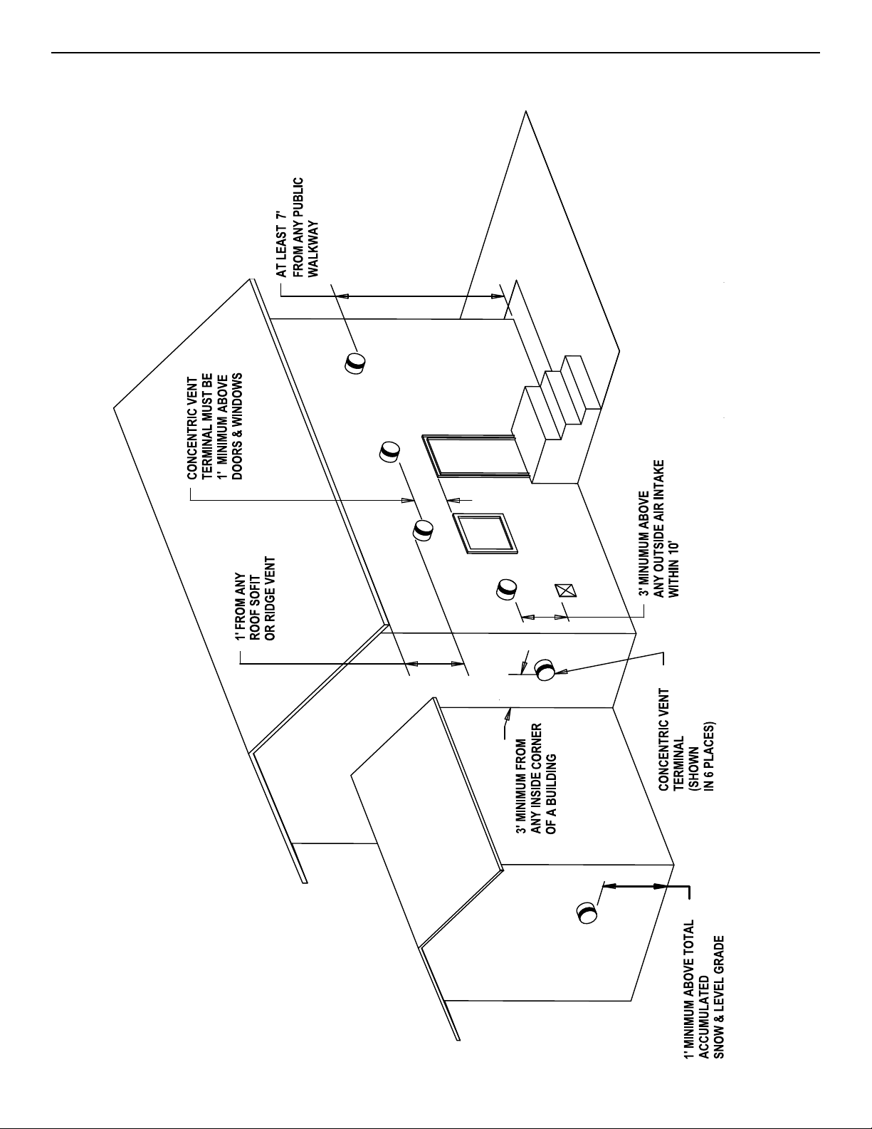
• The terminating vent hood, and the inlet air hood are on
the same wall surface. and are on the wall opposite from
the prevailing wind wall, if possible.
• All of the air for combustion to the burner is supplied
directly from the outside of the building or structure.
• Not less than 12 in. above the total accumulated
snow and level grade.
• Not less than 4 ft. horizontally or below any
window, and door or air inlet and also not less than
1 ft. above any of these openings.
• Not less than 3 ft. above a powered air inlet
device that is within 10 ft.
• Not less than 2 ft. from any other building.
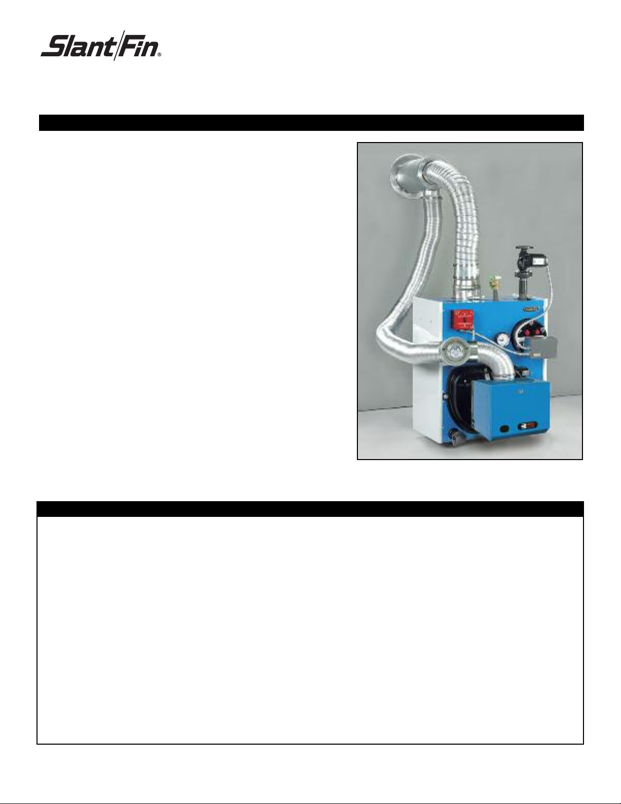
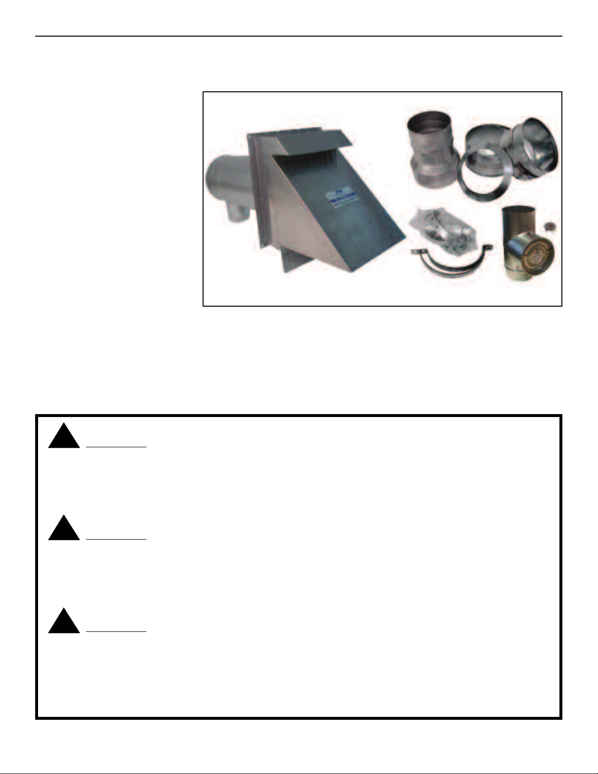
FIGURE 1: Slant/Fin model TRDV oil boiler with
vent kit
• At least 3 ft. from any inside corner of a building
• At least 1 ft. from any roof soffit or ridge vent.
• At least 7 ft. above any public walkway.
• All of the vent construction consists of suitable materials,
and terminates at an approved stainless steel hood.
• All of the vent piping must be sealed from air leaks.
• The vent pipe bend radius is 12 in.
• Brace metal strapping every 36 in. to support
vent pipe and prevent it from sagging.
• Follow the national codes for the installation of oil burning
equipment in USA-NFPA 31, in Canada CAN/CSA - B139
and local regulations.
PUBLICATION NO. TRDV40-V
Printed in U.S.A. 613
Part No. 43-2770
Page 2
2 TRDV SERIES
FLEX- VENT TERMINAL
FIGURE 2: Vent terminal installation locations
Page 3
TRDV SERIES 3
FLEX- L
Do not install vent terminals on prevailing wind wall side of structure.
Moisture and ice may form around terminal. Make sure the surface is in good
repair and protected from damage.
Slant/Fin models TRDV boilers can be installed on sealed or direct vented
systems. They must be ordered from the factory with an approved Direct Vent
System. Part numbers for the kits and accessories can be found on page 8 of
this manual.
NOTE: Vacuum Relief Valve (VRV) not shown. VRV must be located as shown
on page 8.
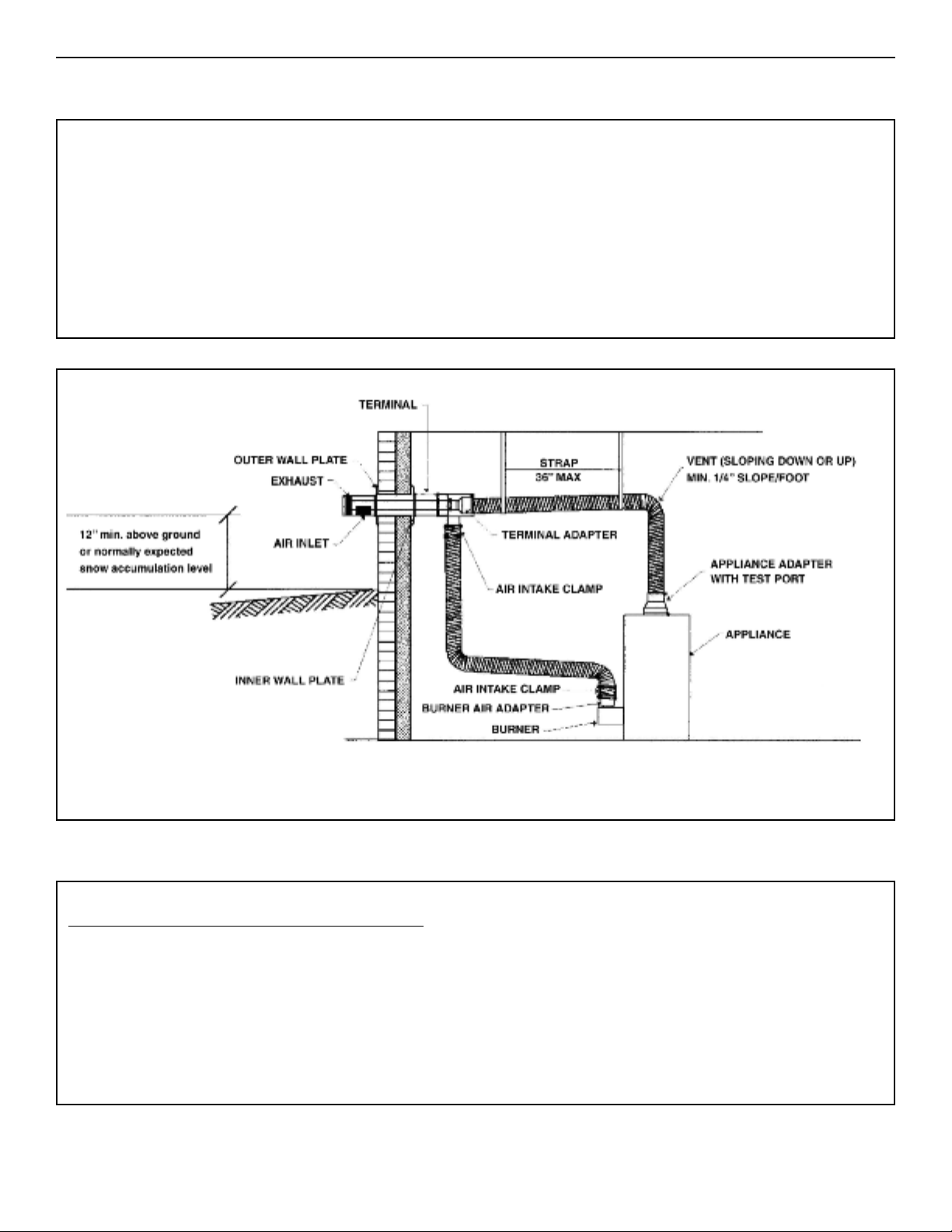
FIGURE 3: Typical installation
ADDITIONAL INSTALLATION CONSIDERATIONS (Figures 2 & 3)
1) Kit or system may vary based on specific needs of appliance.
2) Utilize the appliance adapter test port for combustion testing required by appliance manufacturers.
The vent terminal has a 0” clearance to combustibles
The insulator to vent pipe has 1” clearance to combustibles.
Page 4
4 TRDV SERIES
FLEX- L
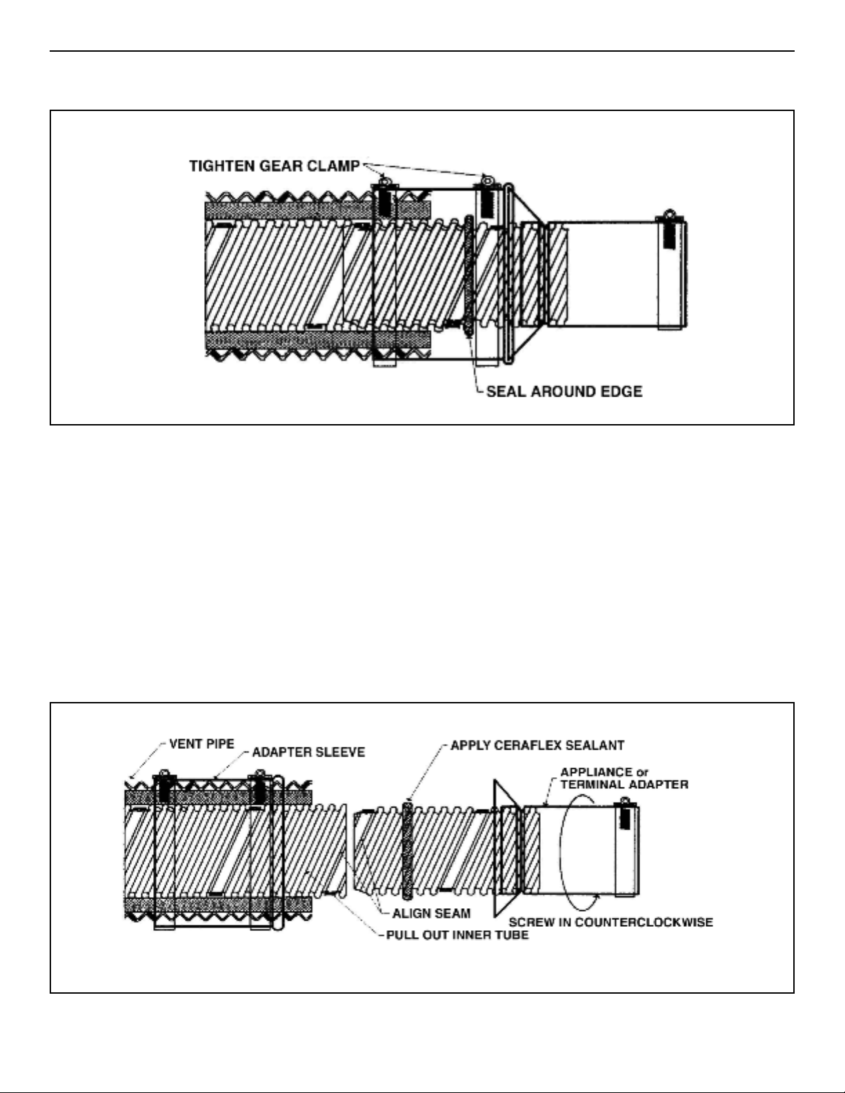
FIGURE 4: Joint assembly
INSTALLING THE JOINT ASSEMBLY
1. Loosen the gear clamps attached to the adapter sleeve and
slide the adapter sleeve over the vent pipe, Figure 4 and
Figure 5.
2. Pull the corrugated inner tube out of the vent pipe for easy
access and insert the adapter.
3. Apply sealant around the corrugated end of the adapter.
4. Align the flat seams at the end of both corrugated tubes and
insert the adapter into the vent tube. Screw the adapter into
the vent pipe with a counter-clockwise motion. The adapter
should be fully inserted into the inner vent tube until it’s tight.
The seams of both tubes must be aligned for ease of insertion.
If the adapter does not completely screw into the vent pipe,
unscrew it and try again as per Step #4.
5. Seal around the edge of vent pipe inner tube.
6. Slide the adapter sleeve back onto adapter and tighten the
gear clamps to complete the connection.
7. If the vent requires cutting to length, a fine tooth hacksaw can
be used. Remove any burrs and flare out the end of the inner
vent tube for easy installation of the adapter.
FIGURE 5: Joint assembly
Page 5
TRDV SERIES 5
FLEX- L
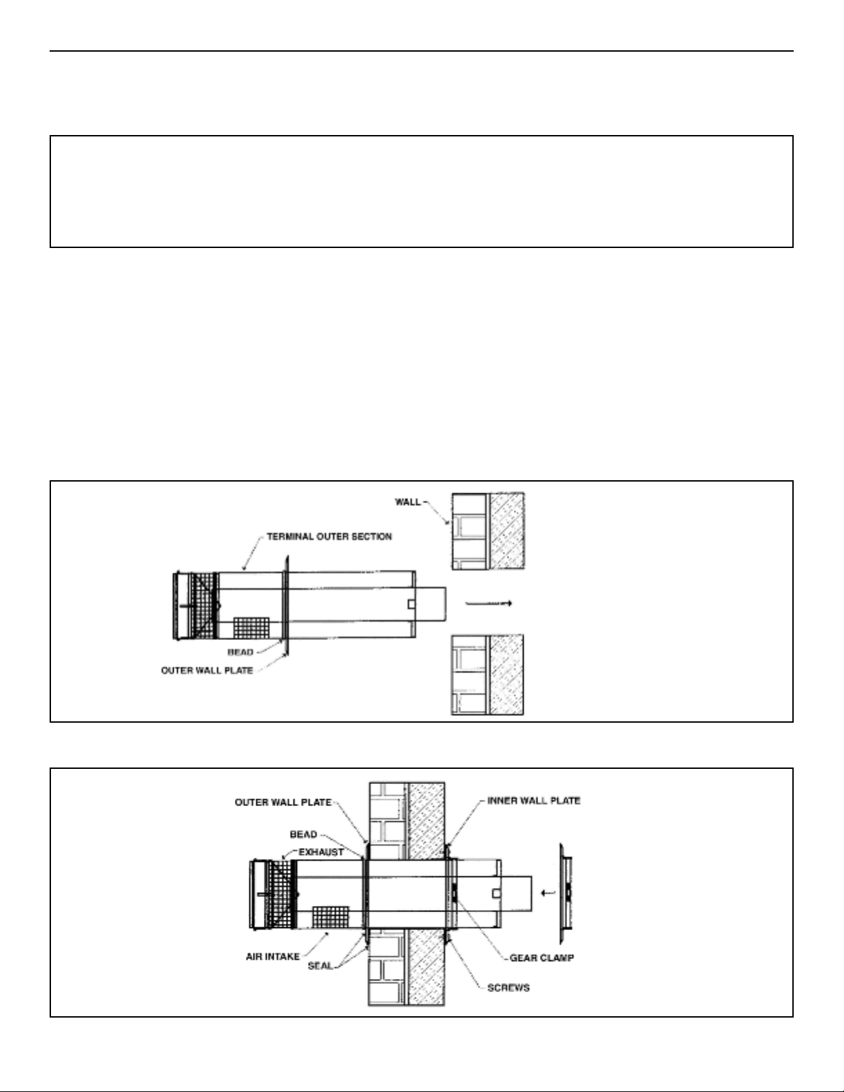
INSTALLING THE OUTSIDE TERMINAL
The maximum wall thickness be no more than 14 in. Contact Slant/Fin for recommendation in
case of a thicker wall.
The system is not designed for common venting. Use for a single appliance only.
Use Figure 6 and Figure 7 to complete the following steps.
1. Determine the terminal location.
2. Cut 8-1/4in. diameter hole through the wall (slightly
larger than the O-D. of the terminal)
3. Pull apart the inner and outer terminal sections.
4. Slide the outer wall plate over the outer section of the terminal
until it rests against the bead.
5. From the outside of the building, insert the outer section
through the hole until it resets against the wall.
6. From the inside of the building, slide the inner wall plate over
the outer and secure using the (4) screws.
7. Position the outer section so the seam on the flue collar is on
the top and the air intake on the bottom. Secure the outer
section by tightening the gear clamp around it. The gear clamp
is factory welded to the inner wall plate.
8. Seal with a weather proof sealant around the bead and edge of
the outer wall plate to prevent water from getting inside.
FIGURE 6: Vent terminal installation into wall
FIGURE 7: Vent terminal mounting
Page 6

6 TRDV SERIES
FLEX- L
CONNECTIONS TO THE OUTSIDE TERMINAL
Use Figure 8 and Figure 9 to complete the following steps.
1. Slide the inner section over the vent pipe.
2. Connect the inner adapter to the vent pipe as per joint
assembly.
3. Apply a bead of sealant around the terminal flue collar.
4. Slide the appliance adapter over the flue collar
. Tighten the gear clamp of the terminal adapter around the flue
5
collar.
6. Seal the seam in the adapter with sealant.
7. Slide the inner section over the outer section and secure by
tightening the gear clamp.
8. Air intake piping is field supplied and must be installed
according to local code requirements. Galvanized flue pipe or
Flex L air intake piping can be used. For optional Flex L air
intake piping, stretch the air intake flex to desired length and
slide over the air intake collar. Seal the connection with the aluminum tape and secure using air intake clamp. Beaded end of
Figure 7) the air intake clamp should go first over the air intake
(
collar.
9. All seams and gaps should be sealed. For the Flex L piping,
seal the gap between the vent pipe and the inner section with
silicone sealant.
FIGURE 8: Vent terminal to flue pipe connection
FIGURE 9: Connection to fresh air intake
Page 7

TRDV SERIES 7
FLEX- L
CONNECTIONS TO APPLIANCE
Using Figures 10 and 11 complete the following steps:
1. Connect the appliance adapter to the vent pipe as per joint
assembly.
2. Apply a bead of sealant around the appliance flue collar.
3. Slide the appliance adapter over the appliance flue collar.
4. Tighten the gear clamp of the appliance adapter around the
flue collar.
5. Seal the seam in the adapter with sealant.
6. Install burner air adapter.
7. Air intake piping is field supplied and must be installed according to local code requirements. Galvanized flue pipe or Flex L air
intake piping can be used. For optional Flex L air intake piping,
tretch the air intake flex to desired length and slide over the air
s
intake collar. Slide the end of the air intake piping over the burner
air adapter. Seal the connection with aluminum tape and secure
using air intake clamp. Beaded end of the air intake clamp
should go first over burner air adapter. See figures 12-13 on the
bottom of this page.
8. A vacuum relief valve must be installed on the air intake side of
the venting system. Locate the vacuum relief valve as close as
possible to burner inlet. Follow the vacuum relief (draft regulator)
manufacturer’s instructions for installation. See figures 14 and 15
for vacuum relief valve.
FIGURE 10: Connection to appliance FIGURE 11: Connection to appliance
Utilize the appliance adapter
test port for combustion testing.
FIGURE 12: Connection to burner
FIGURE 13: Connection to burner
Page 8

8 TRDV SERIES
FLEX-L VENT SYSTEM PART NUMBERS
FIGURE 14: Connection of vacuum relief valve
Item
S/F Part
umber
N
1 43-2771 Vent terminal (Flex L p/n CFT4) required
43-2785 Kit includes: 5 ft. length vent piping,
43-2786 Kit includes: 10 ft. length vent piping,
2
43-2787 Kit includes: 15 ft. length vent piping,
43-2788 Kit includes: 20 ft. length vent piping,
3
43-2779 Riello burner adapter-air intake (Flex L
43-2796 Vacuum relief valve 4” with tee
4
appliance adapter, terminal adapter
and 10 oz. tube silicone (Flex L p/n
CFK054-SF)
appliance adapter, terminal adapter
and 10 oz. tube silicone (Flex L p/n
CFK104-SF)
appliance adapter, terminal adapter
and 10 oz. tube silicone (Flex L p/n
CFK154-SF)
appliance adapter, terminal adapter
and 10 oz. tube silicone
(Flex L p/n CFK204-SF)
p/n CFBA34-RL)
(Field controls p/n 46257100)
Description
required
required
required
one
one
Optional vent system parts:
FIGURE 15: Vacuum relief valve
S/F Part Number
43-2793
43-2794
43-2795
Description
10 oz. tube silicone
3 oz. tube silicone
4” Air Intake Clamp
MAINTENANCE
For the appliance see the installation manual, TRDV-40, for the required maintenance. The vent system must be checked annually by a
qualified heating professional. Vent system must be sealed and the intake and exhaust opening clear of any obstructions.
FIELD CONTROLS VENT SYSTEM PART NUMBERS
Item S/F P/N Description Comment
1 47-0196 EC-16/ TRDV Direct Vent System of:
Field Controls FDVS-46 Direct Vent System &
Field Controls (P/N 46257100) Vacuum Relief Valve
2 43-2774 Field Controls 3-4" Riello Burner Adapter One
One
required
required
3 47-0197
47-0198
Field Controls FOVP-415 (15' of 4” Insultd. Vent Pipe)
Field Controls FOVP-410 (10' of 4” Insultd. Vent Pipe)
One
required
Page 9

TRDV SERIES 9
FIELD CONTROLS
FIELD CONTROLS VENT TERMINAL
Do not install vent terminals on prevailing wind wall side of structure.
Moisture and ice may form around terminal. Make sure the surface is in good
repair and protected from damage.
Slant/Fin model TRDV boilers can be installed on sealed or direct
vented systems. They must be ordered from the factory with an approved
Direct Vent System. Part numbers for the kits and accessories can be found
on page 8 of this manual.
Typical installation. Note: Vacuum relief valve (VRV) not shown. VRV must be located as shown on page 8.
Vent Terminal
Page 10
10 TRDV SERIES
FIELD CONTROLS
ITEMS INCLUDED IN KIT:
FDVS Direct Vent Termination
*VRV-4 Vacuum Relief Valve
Backing Plate
Installation Instruction
Sheet
**Bagged Hardware
**Cover Ring
**Cover Sleeve
**Appliance Adapter
**Adapter Clamp
*Not included in some models
**Included with FOVP (Flex Oil Vent Pipe)
for some models
The Field Direct Vent System (FDVS) is a non-powered positive pressure side wall vent termination system for use only with
specifically listed oil fired appliances. The system provides an outlet for exhaust gases and an intake for combustion air in a single concentric terminal. The FDVS termination is designed to direct the hot exhaust gases away from the structure using the static pressure generated by a special oil burner. All of the internal parts in contact with the flue gases are made from corrosion resistant 316L stainless
steel. The FDVS, with its built-in combustion air tee, allows connecting standard galvanized pipe from the FDVS termination to the air
intake of a special oil burner or by use of a Field Controls Airboot, depending on the model of the oil burner.
FIELD DIRECT VENT SYSTEM
Model: FDVS
!
WARNING:
This system MUST be installed by a qualified agency in accordance with the manufacturer’s installation instructions.
The definition of a qualified agency is: any individual, firm, corporation or company which either in person or through a representative is engaged in, and is responsible for, the installation and operation of oil appliances, who is experienced in such work,
familiar with all the precautions required, and has complied with all the requirements of the authority having jurisdiction.
!
WARNING:
· Read the installation instructions carefully and completely before proceeding with the installation.
· For continued safe operation, the appliance vent system combination is required to be inspected and maintained annually by
a qualified agency. Failure to properly maintain the appliance vent system combination can lead to Death, Personal Injury and
or Property Damage
!
WARNING:
1. Safety inspection of a venting system should be performed before and after installing a venting system on an existing or new
appliance. Procedures to follow are the latest version of those recommended by the National Fuel Gas Code, ANSI Z223.1,
UL-726, NFPA31, CSA B139, CSA B140.0.03 appliance manufacturer’s recommendations, or refer to the General Installation
Inspection section of this manual.
2. Plan the vent system layout before installation to avoid the possibility of accidental contact with concealed wiring or
plumbing inside walls.
Page 11

TRDV SERIES 11
(
a)
(
b)
(c)
(
e)
(g)
(c)
(c)
FIELD CONTROLS
Figure 16. End View
Model “L”
FDVS-4 7-1/4"
Diagram A
INSTALLATION OF FDVS DIRECT VENT SYSTEM
Installation of the Vent Termination
1. Remove vent system components from box and inspect for
damage. If the carton has been crushed or mutilated, check
components very carefully for damage. DO NOT install if
any damage is apparent.
2. Remove the combustion air tee assembly from the vent
termination. Set the tee aside for later use.
3. The location of the vent termination must be installed
according to all local codes that are applicable. In the USA
according to the latest version of the National Fire
Protection Association NFPA-31,National Fuel Gas Code
ANSI Z223.1. Where requirements for venting standards
differ the most stringent standard shall apply. In Canada
according to the latest version of CSA B140 and the
CSA B139 Installation Code. Refer to the following
requirements or See Diagram A for typical locations.
5. Seal the back side of the base plate around the outer pipe
of the vent termination with a bead of high temperature sili
cone sealant. (See Figure 17) Mount the vent termination
through the wall, keeping the outer pipe centered in the
hole. (See Figure 16) Fasten the vent termination to the out
side wall with appropriate fasteners. Seal the edges
of the vent termination base plate to the wall with a hightemperature silicone sealant.
6. Mount the backing plate over the outer pipe. Fasten the
backing plate to the inside wall with appropriate fasteners.
(See Figure 17) DO NOT BLOCK the intake or exhaust
openings, or the intake access panel on the vent
termination body. Wood or vinyl siding should be cut so that
the unit mounts directly on the wallboard to provide a stable
support. If the siding is greater than 1/2" thick use a spacer
plate or board behind the vent termination mounting plate.
(See Figure 17)
Table 1.
a. The exit termination of mechanical draft systems shall
not be less than 7' above grade when located adjacent
to public walkways.
b. A venting system shall terminate at least 3' above any
forced air inlet located within 10'.
c. The venting system of other than a direct vent appliance
shall terminate at least 4' below, 4' horizontally from, or
1' above any door, window or gravity air inlet into the
building.
d. The vent termination of a direct vent appliance with an
input of 50,000 BTU's per hour or less, shall be located
at least 9" from any opening through which vented
gases could enter the building. With input over 50,000
BTU's per hour, a 12" termination clearance shall be
required.
e. The vent termination point shall not be installed closer
than 3' from an inside corner of an L-shaped structure.
f. The vent termination should not be mounted directly
above, or within 3' horizontally from an oil tank vent or
gas meter.
Figure 17. Side View
g. The bottom of the vent terminal shall be located at least
12" above finished grade or expected snow line, which
ever is greater.
4. After determining the location of the venting system
termination (See Diagram A), cut a hole in the wall sized
according to “L” dimension in Table 1. (See Figure 16)
Page 12

12 TRDV SERIES
FIELD CONTROLS
INSTALLATION OF THE VENT TERMINATION
COMBUSTION AIR TEE
1. Assemble the combustion air tee assembly body to the vent
ermination outer pipe, and rotate to the desired position.
t
Attach the tee assembly body to the vent termination outer
pipe with at least 3 sheet metal screws evenly spaced apart
(not included).
. After completing
2
assembly of the
vent pipe to the
termination
nner pipe (Fig. 19),
i
apply the supplied
high temperature
sealant to the cover
pan around the
inner pipe, around
the joint between
the collar and the Tee assembly, and seal or
tape the joint from the FDVS Termination to the Tee assembly.
NOTE: The tee may be rotated into any position so that the collar
is in a convenient orientation.
CLEARANCE TO COMBUSTIBLES: FDVS Termination: 0",
FOVP Flexible Oil Vent Pipe: 1". These clearances are to maintained unless superceded by National and/or local codes
(see Step 3).
CONNECTING THE VENT PIPE FROM THE FDVS
TO THE APPLIANCE
1. The venting system should be installed and supported in
accordance with the latest version in the USA of the National
Fuel Gas Code ANSI Z223.1, UL-726, National Fire
Protection Association NFPA31, and in Canada CSA B140,
CSA B139 Installation Code or in accordance with any other
local codes or the authority having jurisdiction. Where
requirements for venting differ the most stringent standard
requirements shall apply. A vent pipe connector, designed for
positive pressure venting, shall be supported for the design
and weight of the material employed, to maintain clearances,
prevent physical damage and separation of joints. All joints
MUST be sealed, for positive vent pressure, to prevent flue
gas leakage into the structure.
2. Route the vent pipe from the appliance to the vent termination
using the minimum number of bends as possible. The last
horizontal section of the vent pipe should have a slight downward slope from the appliance to the vent termination. For
clearances to combustible materials and other installation
requirements, refer to the National Fuel Gas Code ANSI
Z223.1, UL-726, NFPA31, CSA B140, CSA B139 and/or any
applicable local codes.
3. The maximum length of vent pipe run for the EC-10DV boiler
series is 15 feet. The minimum diameter of the approved vent
pipe is 4" for the EC-10DV boiler series. Use a reducer or
increaser, if necessary, at the vent termination to connect the
vent pipe.
4. Support the Flexible Oil Vent Pipe (FOVP) at regular intervals
of maximum 36" spacing with appropriate strapping or hangers, per National and local code requirements. Do not install
screws into or otherwise penetrate any part of the vent pipe
under any circumstances.
Figure 18 - Top View
CONNECTING THE COMBUSTION AIR INTAKE PIPE FROM
THE FDVS TO THE APPLIANCE
1. Use 4" galvanized steel pipe or stainless steel pipe from the
DVS terminal combustion air tee collar to the appliance oil
F
burner combustion air inlet (or Air boot, if applicable.) Use a
reducer or increaser, if necessary at the burner combustion air
inlet to connect the combustion air intake pipe.
. The VRV should be installed close to the air inlet of the
2
burner, see fig. 14 on page 8.
GENERAL INSTALLATION INSPECTION
ecommended procedures for safety inspection of an appliance
R
should be in accordance with the latest version of the National
Fuel Gas Code ANSI Z 223.1, UL 726, and the National Fire
Protection Association NFPA 31 in the USA, CSA B140 and CSA
B139 Installation Code in Canada. The following procedure will
help evaluate the venting system. It is intended as a guide to aid
in determining that the venting system is properly installed and is
in a safe condition for continuous use. This procedure should be
recognized as a generalized procedure which cannot anticipate
all situations. Accordingly, in some cases, deviation from this procedure may be necessary to determine safe operation of the
equipment. If it is determined that a condition exists which could
result in unsafe operation, the appliance should be shut off and
the owner advised of the unsafe condition. Corrections must be
made before the appliance is put into continuous operation. The
following steps should be followed in making a safety inspection.
1. Visually inspect the venting system for proper size and deter
mine that there is no flue gas spillage, blockage, restriction,
leakage, corrosion, or other deficiency which could cause an
unsafe operation.
2. Place in operation the appliance being inspected. Follow the
lighting instructions and adjust thermostat so appliance will
operate continuously.
3. Determine that the burner is operating properly and that the
burner ignition operates satisfactorily by interrupting and
reestablishing the electrical power of the appliance in any
convenient manner. Test the burner safety device to determine
if it is operating properly by disconnecting the flame
safety circuit.
4. Test for spillage at the burner inlet air location around the VRV
after 5 minutes of operation. Use a draft gauge, flame of a
match or candle, or smoke from a cigarette, cigar or pipe.
Shut off appliance thermostat and check for spillage around
the VRV. If a flow reversal is noticed, house depressurization
is occurring and make up air is required.
MAINTENANCE
Inspect all vent connections annually for looseness, evidence of
corrosion, or flue gas leakage. Replace, seal, or tighten pipe
connections if necessary. As part of the yearly maintenance
schedule, remove the Intake Access Panel on the exterior of the
FDVS vent termination (See Figure 17) and remove any debris or
foreign material. Be sure to properly replace the panel.
Page 13

TRDV SERIES 13
FIELD CONTROLS
REFER TO PAGE 8 FOR VACUUM RELIEF VALVE CONNECTIONS AND VENT SYSTEM PART NUMBERS
APPLIANCE ADAPTER INSTALLATION:
1. Apply a bead of sealant to appliance collar approx. 1” from
end of collar (Figure 20).
2. Remove all oil and grease from the inside of the appliance
adapter, and apply a bead of sealant to inside of adapter ?”
from end (Figure 20).
3. With a twisting motion, assemble the appliance adapter onto t
he appliance collar.
4. Using a mallet and block of wood, drive the adapter onto the
appliance collar, using care to avoid damaging the appliance
collar or the adapter (Figure 21).
5. Assemble adapter clamp halves using the supplied 5/16” bolts
and square nuts, and install the appliance clamp onto the
adapter and tighten securely (Figure 20).
6. Install the supplied self-drilling, self-tapping anchoring screws
through the 4 holes in the appliance clamp into the appliance
collar (Figure 21). No pilot hole is required.
7. Apply sealant to the end of the adapter and anchoring screws.
(Figure 21).
8. After testing and burner adjustments have been made, apply
sealant to the supplied 3/8” sampling port plug screw and
install the screw in the sampling port (Figure 21).
9. Maintain the following clearances to combustibles. If the
appliance collar is within 18" of combustible material, wrap
minimum 1-1/2" ceramic insulation (installer-supplied) around
the exposed portion of the termination inner pipe and
appliance adapter (Figure 25).
Figure 19
Figure 20
Figure 21
Page 14

14 TRDV SERIES
FIELD CONTROLS
REFER TO PAGE 8 FOR VACUUM RELIEF VALVE CONNECTIONS AND VENT SYSTEM PART NUMBERS
JOINT ASSEMBLY: VENT PIPE TO TERMINATION
AND APPLIANCE ADAPTER
If necessary, the vent pipe may be cut to length with a hacksaw or
cut off saw.
CAUTION: Use safety glasses and other appropriate safety gear.
1. Pull outer vent pipe back 1”-2” from inner vent pipe end and
remove insulation (Figure 22).
2. Slide Cover Sleeve onto end of vent pipe a few inches back
from end of outer vent pipe (Figure 22).
3. Slide Cover Ring over stop bead on termination inner pipe or
appliance adapter (Figure 22).
4. Assemble inner pipe clamp halves using the supplied
and square nuts, and position inner pipe clamp
inner pipe (Figure 22).
5. Remove all oil and grease from end of termination inner pipe
or appliance adapter, and apply a bead of sealant to between
the stop bead and retainer bead (Figure 23).
6. Apply a thick bead of sealant to inside of inner vent pipe
from the end of pipe, working the sealant into the corrugations
(Figure 23).
7. Push the inner vent pipe onto the termination inner pipe or
appliance adapter all the way up to the stop bead.
8. Tighten the inner pipe clamp bolts until both clamp halves are
within 1/8" of each other at each end (Figure 24).
9. Slide the cover sleeve and cover ring together to engage the
ring in the groove of the sleeve, and tighten the cover sleeve
clamp (Figure 25).
10.To maintain 1" clearance to combustibles, wrap minimum
1-1/2" thick ceramic insulation (installer-supplied) around the
exposed portion of the termination inner pipe (Figure 25), and
secure with foil tape (installer supplied).
1
⁄4” bolts
1
⁄4” from end of
1
⁄2”
Figure 22
Figure 23
Figure 24
Figure 25
Page 15

TRDV SERIES 15
Notes:
Page 16

SLANT/FIN CORPORATION, Greenvale, N.Y. 11548 • Phone: (516) 484-2600
FAX: (516) 484-5921 • Canada: Slant/Fin LTD/LTEE, Mississauga, Ontario
www.slantfin.com
 Loading...