

Page 1
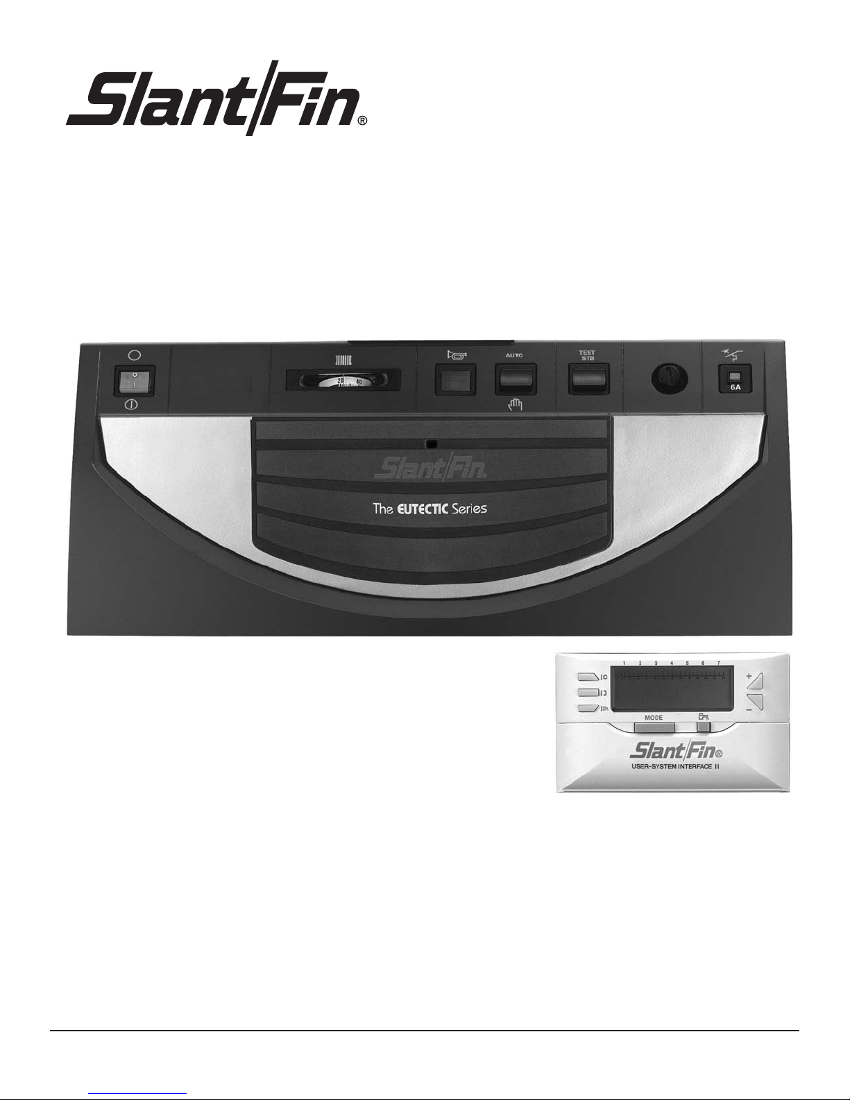
THERMATIC II CONTROL PANEL
Usage,
electrical connection
and start up instructions
Part No. 470902000
Page 2

2
CONTENTS
1. GENERAL . . . . . . . . . . . . . . . . . . . . . . . . . . . . . . . . . . . . . . . . . . . . . . . . . . . . . . . . . . . . . . . . . . . . . . . . . . 3
1.1 Presentation . . . . . . . . . . . . . . . . . . . . . . . . . . . . . . . . . . . . . . . . . . . . . . . . . . . . . . . . . . . . . . . . . . . . . 3
1
.2 Operating principle . . . . . . . . . . . . . . . . . . . . . . . . . . . . . . . . . . . . . . . . . . . . . . . . . . . . . . . . . . . . . . . . 3
1.3 Technical characteristics . . . . . . . . . . . . . . . . . . . . . . . . . . . . . . . . . . . . . . . . . . . . . . . . . . . . . . . . . . . . 3
2. DESCRIPTION . . . . . . . . . . . . . . . . . . . . . . . . . . . . . . . . . . . . . . . . . . . . . . . . . . . . . . . . . . . . . . . . . . . . . . 4
3. STARTUP OR RESTART AFTER A PROLONGED STOP . . . . . . . . . . . . . . . . . . . . . . . . . . . . . . . . . . . . 5
4. CHOOSING THE OPERATING MODE . . . . . . . . . . . . . . . . . . . . . . . . . . . . . . . . . . . . . . . . . . . . . . . . . . . . . 6
4.1 Automatic operation . . . . . . . . . . . . . . . . . . . . . . . . . . . . . . . . . . . . . . . . . . . . . . . . . . . . . . . . . . . . . . . 6
4.2 Summer operation . . . . . . . . . . . . . . . . . . . . . . . . . . . . . . . . . . . . . . . . . . . . . . . . . . . . . . . . . . . . . . . . . 6
4.3 Manual operation . . . . . . . . . . . . . . . . . . . . . . . . . . . . . . . . . . . . . . . . . . . . . . . . . . . . . . . . . . . . . . . . . 6
5. HEATING AND DOMESTIC HOT WATER SET TEMPERATURES . . . . . . . . . . . . . . . . . . . . . . . . . . . . . . . . 8
6. SETTING THE TIME AND DAY . . . . . . . . . . . . . . . . . . . . . . . . . . . . . . . . . . . . . . . . . . . . . . . . . . . . . . . . . . 8
7. PROGRAMMING . . . . . . . . . . . . . . . . . . . . . . . . . . . . . . . . . . . . . . . . . . . . . . . . . . . . . . . . . . . . . . . . . . . . . .9
7.1 Factory programming . . . . . . . . . . . . . . . . . . . . . . . . . . . . . . . . . . . . . . . . . . . . . . . . . . . . . . . . . . . . . . . 9
7.2 Program customization . . . . . . . . . . . . . . . . . . . . . . . . . . . . . . . . . . . . . . . . . . . . . . . . . . . . . . . . . . . . . 9
8. MESSAGES - ALARMS . . . . . . . . . . . . . . . . . . . . . . . . . . . . . . . . . . . . . . . . . . . . . . . . . . . . . . . . . . . . . . 10
9. ISOMETRIC VIEWS AND SPARE PARTS LIST . . . . . . . . . . . . . . . . . . . . . . . . . . . . . . . . . . . . . . . . . . . . . 11
10. INSTALLER SECTION . . . . . . . . . . . . . . . . . . . . . . . . . . . . . . . . . . . . . . . . . . . . . . . . . . . . . . . . . . . . . . . 14
11. WIRING DIAGRAMS . . . . . . . . . . . . . . . . . . . . . . . . . . . . . . . . . . . . . . . . . . . . . . . . . . . . . . . . . . . . . . . . . 16
12. INSTALLING USER-SYSTEM INTERFACE IN LIVING AREA . . . . . . . . . . . . . . . . . . . . . . . . . . . . . . . . . . 20
13. INSTALLING USER-SYSTEM INTERFACE IN BOILER CONTROL PANEL . . . . . . . . . . . . . . . . . . . . . . .21
Page 3

3
The boiler must be connected by a qualified
p
rofessional. Strict compliance with these
usage, electrical connection and start up
instructions is a precondition for the correct
operation of the boiler.
1. GENERAL
1.1 Presentation
The E control panel with an Thermatic regulator
(user-system interface) to be fixed to the wall or
integrated into the boiler control panel can be used
for:
- automatic operation of heating when the ambient
temperature has been reached
- control of heating as a function of the outside temperature.
- regulation and programing of domestic hot water production (if it is present) with or without priority
- providing a frost free room temperature if the home is
empty. The duration of this period may be programed
up to 99 days.
The basic delivery of the T control panel comprises
- 1 T control panel
- 1 Thermatic regulator (user-system interface) with
support to be installed in the chosen room or to be included in the control panel.
- 1 boiler sensor measuring the water temperature in
the boiler
- 1 external sensor
Options
The following option can be ordered:
- domestic hot water sensor (package FM 45).
1.3 Technical characteristics
The T control panel can be used to program and regulate the room temperature as a function of the outside
temperature by controlling the burner. The boiler
thermostat must be set to a sufficiently high temperature for automatic regulation to operate correctly
The safety thermostat with auto reset (adjusted to
110°C/230°F) maintains operating safety.
In the case of domestic hot water (d.h.w.) production,
domestic hot water is regulated by the regulator acting
on the load pump giving priority to heating of domestic
hot water.
When a request is made for heating domestic hot
water, the domestic hot water priority stops the burner
and the d.h.w. load pump and stops the heating pump.
Under summer conditions, the boiler is not kept hot
between two domestic hot water loads. The domestic
hot water temperature is measured by the d.h.w.
sensor.
The regulator includes the possibility of a "antilegionellosis" protection.
1.2 Operating principle
Temperature Resistance
in °C / °F in Ohm
- 20°C / -4°F 2 392 Ω
- 16°C / 3°F 2 088 Ω
- 12°C / 10°F 1 811 Ω
- 8°C / 18°F 1 562 Ω
4°C / 25°F 1 342 Ω
0°C / 32°F 1 149 Ω
Temperature Resistance
in °C / °F in Ohm
4°C / 39°F 984 Ω
8°C / 46°F 842 Ω
12°C / 54°F 720 Ω
16°C / 61°F 616 Ω
20°C / 68°F 528 Ω
24°C / 75°F 454 Ω
- Electrical power supply: 120V - 60 Hz
- Clock operating capacity: 2 years minimum
- Resistance of the external sensor in Ω (option)
- Value of water sensors in Ω
Temperature Resistance
in °C / °F in Ohm
0°C / 32°F 32 014 Ω
10°C / 50°F 19 691 Ω
20°C / 68°F 12 474 Ω
25°C / 77°F 10 000 Ω
30°C / 86°F 8 080 Ω
40°C / 104°F 5 372 Ω
Temperature Resistance
in °C / °F in Ohm
50°C / 122°F 3 661 Ω
60°C / 140°F 2 535 Ω
70°C / 158°F 1 794 Ω
80°C /176°F 1 290 Ω
90°C / 194°F 941 Ω
- EC-10, EC-20 and EC-100.
Page 4
4
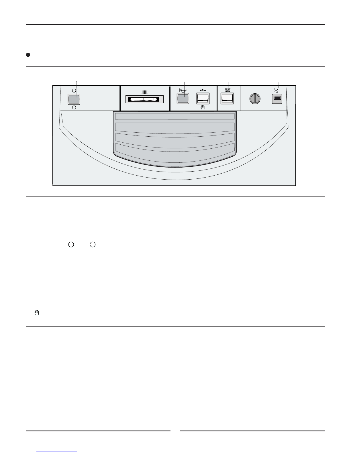
2.
DESCRIPTION
Control panel
0
I
6A
20°C40
8578N007
A. Timed circuit breaker (6 A)
B. Safety HIGH LIMIT with auto reset
(Set to 110°C / 230°F)
C. Power/Main /Off switch.
Note:we recommend leaving the boiler on during the
summer, particularly so that the heating pump cleaning function can remain in operation. It is preferable
to use "summer" mode for the period during which the
heating is to be cut off.
D.
2-position switch
AUTO : automatic operation
(manual) : forced operation
E.
"Test-STB" push button
When pushed and held in, safety
HIGH LIMIT
tests
and cutoff of the heating pump.
F. A larm light
This light is disabled.
H. Boiler temperature gauge
C
F
D
EBA
H
Page 5

5
3. STARTUP OR RESTART AFTER A PROLONGED STOP
0
I
6A
20°C40
8
578N007
STANDARD
MODE
PROG
PROG
+
-
1
234567
024
6810
1
2
141618 20 22
24
8575N078
Initial starting up shall be performed by the installer.
Before turning the boiler on, make sure that the install
ation is filled with water. Startup in the chronological
order described below:
C
D
B
6
1
5
7
The set temperature of the heating circuit and the
domestic hot water average storage temperature (if
there is an indirect d.h.w. tank) can be adjusted at
any time using key 1 (see chapter 4).
Select the operating mode using keys 5, 6 and 7
(see chapter 2).
Customize the heating program and the d.h.w. program
as you wish if you have domestic hot water production
(see chapter 6).
Check that the switch D is in the AUTO position.
Put the On/Off switch C into the On position.
Note
For production of domestic hot water (d.h.w. sensor
connected), an automatic bleed sequence is carried
out of the indirect d.h.w. exchanger for one minute by inter-
mittent operation of the domestic hot water pump and
the heating circulator pump, before changing to auto-
matic operation mode.
This bleed sequence is only activated if the indirect d.h.w.
tank temperature is greater than 25°C / 77°F.
Page 6
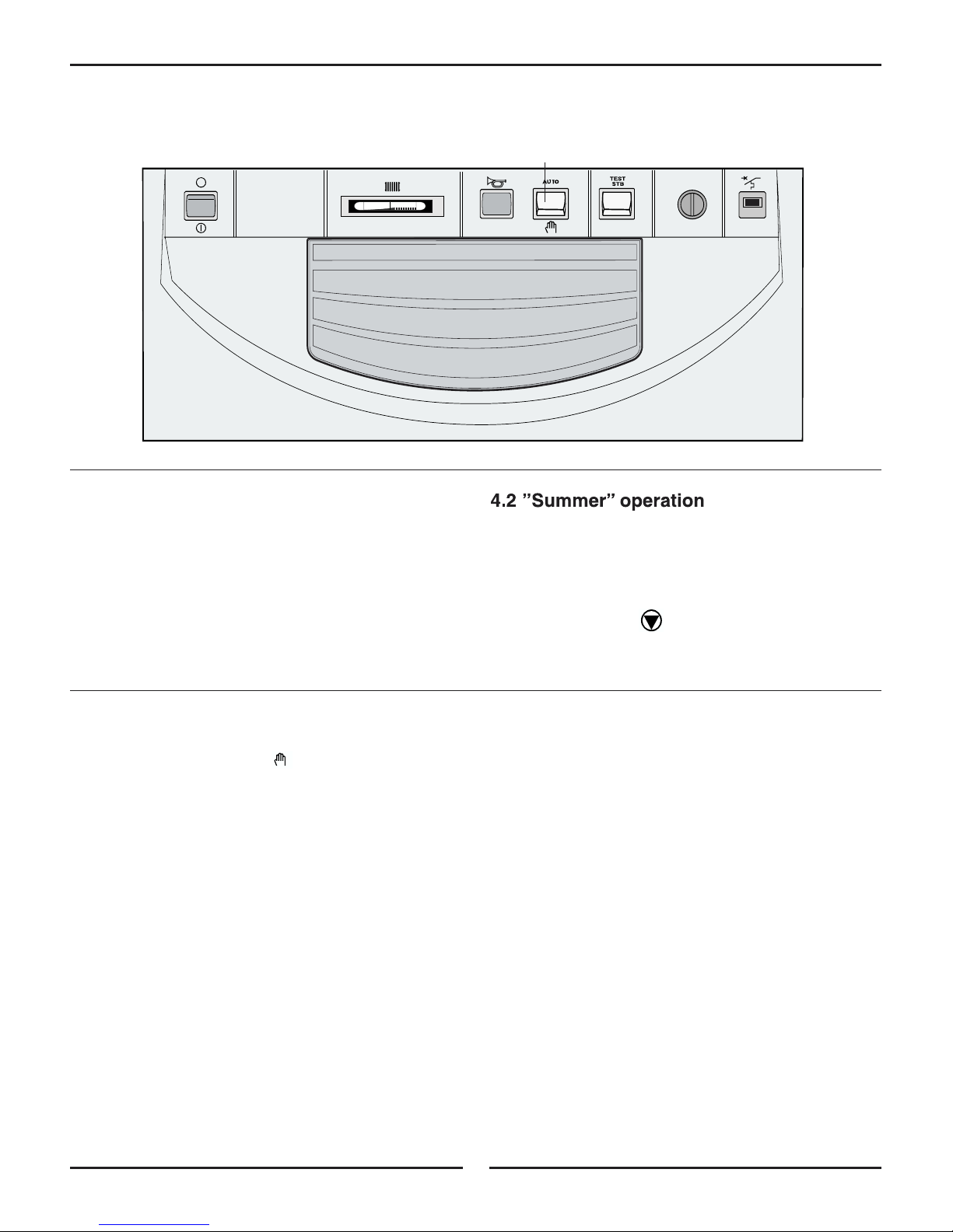
4. CHOOSING THE OPERATING MODE
D
Put the switch D in the AUTO position.
This position enables automatic regulation and
operation by the Thermatic regulator.
4.1 Automatic operation
0
I
6
A
2
0
°
C
4
0
8578N007
4.3 Manual operation
Put switch D to its position .
This position may be selected to make the boiler setting, for example, or if there is a problem with the electronic regulation:
- the burner is put into forced operation
- the boiler will operate according to the set temperature
at the regulator.
- the heating pump and the domestic hot water load
pump (if there is an indirect d.h.w. tank) are started the display is off.
Heating is automatically cut off during the summer
when the outside temperature is higher than the ”comfort” temperature setting for 2 hours.
The display remains identical, but the circulator pump is
permanently off.The symbol is no longer displayed.
Heating is started again when the outside temperature drops below the ”comfort” temperature for 2 hours.
6
Page 7
7
STANDARD
MODE
PROG
PROG
+
-
1234567
024
68101214
1
6
18 20 22
2
4
8575N078
4
2
6
1
5
7
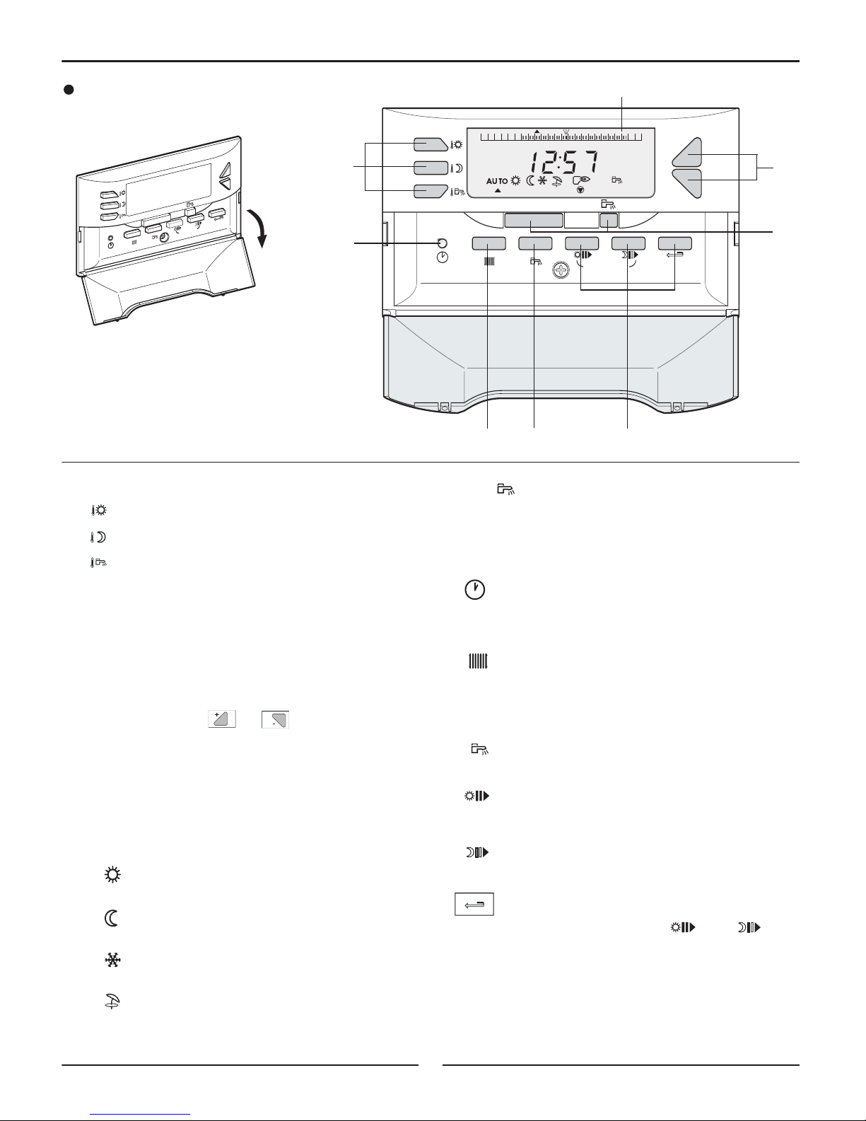
3
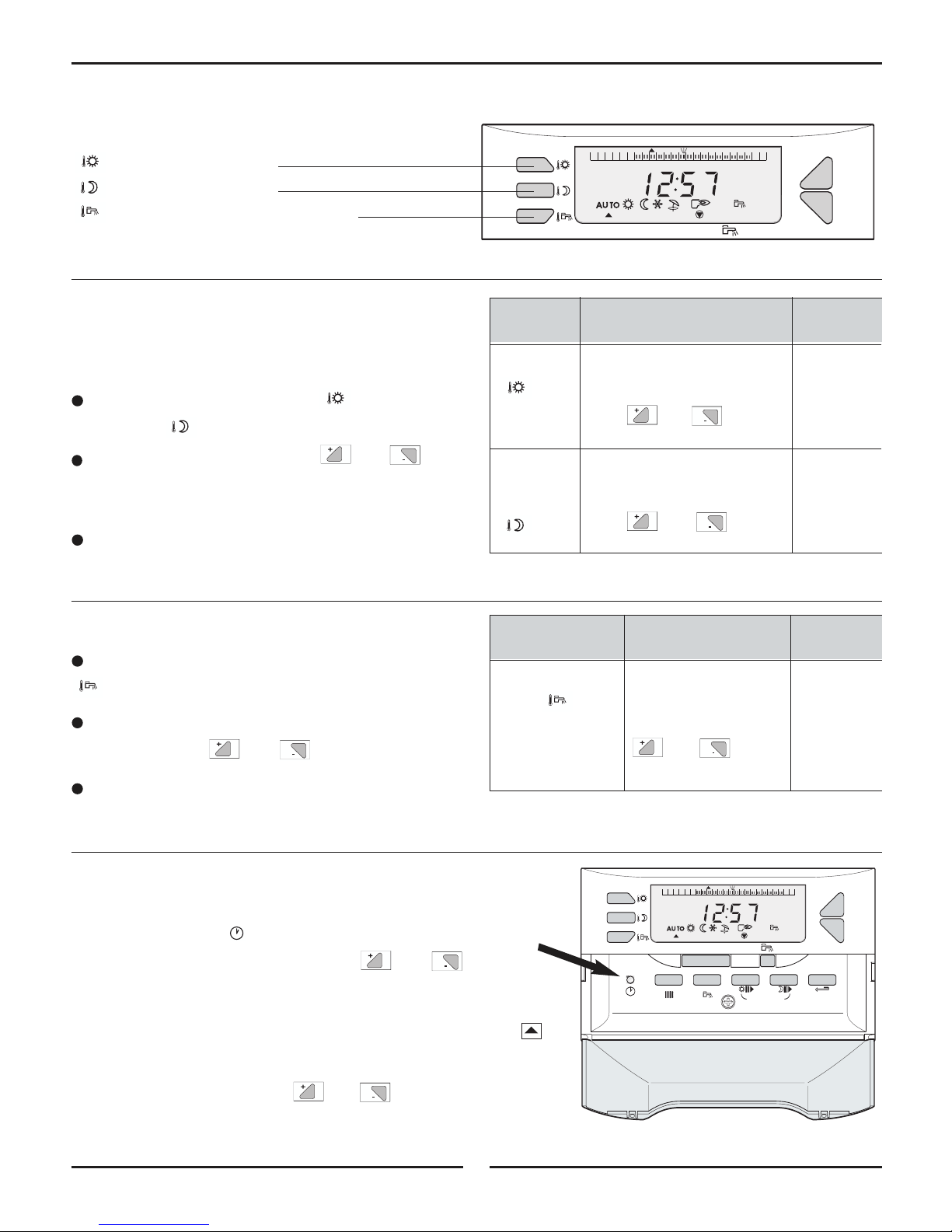
Thermatic regulator (user-system interface)
Flap open
1. Temperature adjustment keys (green keys)
"comfort" temperature
"low" temperature
"domestic hot water" temperature (if an
indirect d.h.w. tank is connected)
Note
When one of these keys is pressed:
- the active time program corresponding to the circuit is displayed in the graphic bar
- the measured temperature is displayed at the right
of the display.
2. Adjustment keys or (blue keys)
3. Operating mode selection keys (grey keys)
MODE key
To s elect one of the following operating modes:
AUTO : operation according to the time pro-
gram
:forced operation at comfort tempera-
ture until midnight
:forced operation at reduced tempe-
rature until midnight
: frost free operation during the pro-
grammed time
:stop manual heating, production of
domestic hot water only (if an indirectd.h.w. tank is connected)
Key
To fo rce heating of the domestic hot water tank outside the d.h.w. time program (if an indirect d.h.w. tank
is connected).
4. Time and day adjustment key
5. Key to adjust the heating program
PROG
6. Key to adjust the indirect domestic hot water tank
program
PROG
7. Programing keys
write (in 1/2 hour periods) the “comfort”
period or the indirect d.h.w. tank heating allowed
period (dark area)
write (in 1/2 hour periods) the “low”
period or the indirect d.h.w. tank heating not
allowed period (light area)
return to the program graphic bar
Simultaneously press the and keys
(STANDARD) for 5 seconds to reinitialize
programs to factory settings: heating and
d.h.w. from 6 a.m. to 10 p.m.
8. Program display graphic bar (12 a.m. to 12 p.m.)
"Comfort" periods are displayed in black bars at
programmed "comfort" times in the graphic bar.
S
T
A
N
D
A
R
D
MO
D
E
P
R
O
G
P
R
O
G
+
-
1
2
3
4
5
6
7
8575N077
8
Page 8
8
MODE
+
-
1234567
024
6810
1
2
14
1
6
18 20 22
2
4
5. HEATING AND DOMESTIC HOT WATER SET TEMPERATURES
8
575N079
Heating set temperature
Temperatures for "comfort" periods (dark area in the
graphic bar) and for "reduced" periods (light area in the
graphic bar) can be adjusted as follows:
Select the comfort temperature or the reduced
temperature .
Adjust the temperature using the and keys.
Note: the graphic bar displays the heating program for
the current day for the displayed circuit.
End of setting: after the setting is completed, the
normal display reappears after 2 minutes or when the
MODE key is pressed.
Indirect d.h.w. tank set temperature
Select the domestic hot water temperature using the
key.
Adjust the average domestic hot water storage tem-
perature using the and
keys.
End of setting: after the setting is completed, the
normal display reappears after 2 minutes or when the
MODE key is pressed.
Tem pe-
Setting range
Factory
gnitteserutar
Domestic hot
10°C to 80°C / 50°F to 175°F
water Adjustment in steps of
55°C / 130°F
(average 1°C / 5°F using
storage
and
temperature)
Tem pe-
Setting range
Factory
gnitteserutar
Comfort 5 to 30°C / 41°F to 86°F
Setting in steps of 0.5°C / 1°F 20°C / 68°F
using and
Reduced 5 to 30°C / 41°F to 86°F
temperature
Setting in steps of 0.5°C / 1°F 16°C / 60°F
using and
6. SETTING THE TIME AND DAY
STANDARD
MODE
PROG
PROG
+
-
1234567
024
6
810121
4
16
1
8 20 22
24
-Open the flap.
-Press the clock key using the tip of a ball point pen and then
adjust the time and the day using the and keys.
Press once to make a minute by minute setting.
Press again for hour by hour setting.
Press a third time for day by day setting by putting the arrow
in the graphic bar from 1 to 7 (1 = Monday)
Note:
A prolonged press on the or key increases the
scrolling speed.
A fine setting can be made by making short presses.
8575N078
Note: if there is no domestic hot water sensor, pressing this key has no effect.
:
”comfort” temperature
:”reduced” temperature
: "domestic hot water" temperature
Page 9
9
Days
D.H.W. heating
allowed
Monday
Tu esday
Wednesday
Thursday
Friday
Saturday
Sunday
7. PROGRAMING
7.1 Factory programing
Heating program
M
onday to Sunday: 6 a.m. to 10 p.m. : Comfort period
Indirect domestic hot water tank program
Monday to Sunday: 5 a.m. to 10 p.m. : Loading allowed
7.2 Program customization
Enter customized programs in the adjacent tables,
then save them as follows:
Press the PROG key to select the heating pro-
gram or PROG to select the d.h.w. program.
Select the day by pressing the PROG or PROG
keys several times.
Note:the program chosen for every weekday is automatically copied to other days but it can be modified
individually day by day.
Write dark areas using the key and write light
areas using the key (1/2 hour by 1/2 hour).
- Dark areas are applicable to "comfort" heating
or tank heating allowed periods.
- Light areas are applicable to "reduced" or
Indirect d.h.w. tank heating not allowed periods.
Use the key to come back in the event of any
error.
End of programming: Press the MODE key. Otherwise,
the program will be validated automatically after 2
minutes.
Note
Pressing the and keys simultaneously (STANDARD) for 5 seconds reinitializes the programs to the factory settings indicated in § 6.1 above.
Customized programs
HEATING PROGRAM
INDIRECT DOMESTIC HOT WATER TANK
PROGRAM DHW
Day
"Comfort" period
Monday
Tu esday
Wednesday
Thursday
Friday
Saturday
Sunday
Page 10

10
In the event of any malfunction, the following messages may appear on the display:
YDEMERESUACELBABORPTLUAFEGASSEM
AALL 5
5
5
5
55
00
Boiler sensor The corresponding Switch off the electrical power supply to the boiler using the
AALL 11
External sensor sensor On/Off switch to erase this message, and inform your fitter.
AALL 22
D
.h.w. sensor circuit is broken
However, you can operate the part of the installation concerned
AALL AA
R
oom sensor or is short circuited in ”Manual” mode. See comments below.
8. MESSAGES - ALARMS
AALL 00
and
AALL 11
The entire installation automatically changes to
”Manual” mode
- The heating circulator pump runs permanently and the
valve is no longer regulated electrically. It may be control-
ed manually if necessary.
AALL 22
The domestic hot water is no longer heated automatically. You can continue to produce domestic hot water
by changing to manual conditions using the ”AUTO/
” switch - see chapter 3. The d.h.w. heating temperature is equal to the boiler temperature.
AALL AA
Automatic operation in configuration without room
sensor.
Note:
If a fault occurs in a sensor, the installation continues to
operate with the following limitations and displays:
5
5
Page 11

Note : when ordering spare parts, do not forget to provide the code number given in the list opposite the part reference.
11
9. ISOMETRIC VIEWS AND SPARE PARTS LIST
Page 12

DHW SENSOR OPTION ( PACKAGE FM 45)
THERMATIC control panel
990
992
995
994
993
991
85757740A
EXTERNAL SENSOR
85757741
951
950
952
12
Page 13

13
T control panel
CONTROL PANEL
1 8578-7001
Complete Thermatic control panel
2 8578-8506 Complete Thermatic card cover
3 9786-4039 Thermatic front panel
4 9532-5027 Green On/Off two-pole switch
5 8500-0035 Two-pole switch
6 9532-5028 Moment inverter two pole switch
7 8500-0032 110°C safety thermostat
8 8500-0002 30-90 °C setting thermostat
9 9752-5181 Setting button
10 9534-0288 Circuit breaker 4A TS710/4A
11 9536-5147 Flat thermometer
12 9521-6220 Red light
13 8806-7511 Thermatic module CDC 2 (user-system interface)
14 9655-0352 WSBH-2 harness fastening
15 8575-8019 Board supports
16 8578-4905 D.H.W. harness
17 8578-4906 Burner cable
18 8806-5565 Thermatic relay board
19 8575-4905 3-pin connector power supply
20 8575-4922 4-pin connector power supply VA+CS
21 8575-4924 Pump 3-pin connector A/VS
22 8575-4918 2-pin connector boiler sensor
23 8575-4911 EPT2-pin connector room sensor
24 8575-4928 EPT connector RT
25 8575-5520 Control panel screw bag
26 9655-0357 8-pin flat cable L = 300
27 8575-4918 KVT 60 sensor - length 1 m
EXTERNAL SENSOR
950 8575-7741 External sensor (Package FM46)
951 9536-2450 External sensor AF60
952 8575-4906 2-pin external sensor connector
DHW SENSOR OPTION (PACKAGE FM 45)
990 8575-7740 D.h.w. sensor (Package FM 45)
991 8575-4935 Installed d.h.w. sensor
992 8575-4909 D.h.w. sensor 2-pin connector
993 9536-2448 KVT 60 sensor L = 5M
994 8575-4925 2-pin external connector d.h.w. sensor
995 9536-5613 Contact spring for thimble tube
Mark. Code No. DESCRIPTION Mark. Code No. DESCRIPTION
10/09/03
Page 14

14
ASSEMBLY,ELECTRICAL CONNECTIONS & INSTALLER SETTINGS
T control panel
This page is reserved for use by the installer
•
Assembling the control panel
Refer to the assembly sheet provided with the
boiler instructions.
•
Installing the boiler sensor
Refer to the assembly sheet provided with the
boiler instructions.
1/
2
H
H
(2.5 m min.)
1/
2
Z
Z
1/
2
H
(2.5 m min.)
H
8800N001
Installation :
The outside sensor is fixed to the outside wall using the
supplied accessories: (wood screws + inserts).
8800N002A
8800N003
Positions to be avoided:
•
Installing the outside sensor
The outside sensor is installed on the outside wall adjacent to the heated area. It must be easily accessible.
H
:inhabited height to be checked by the sensor
:recommended position on a corner
:possible position (if difficulties are encountered)
Z
:inhabited area to be checked by the sensor
The sensor must be placed on the outside wall so that
it is directly influenced by weather variations, but is not
directly influenced by solar radiation.
10. INSTALLER SECTION
Page 15

15
Electrical connections shall be carried out
by a qualified professional only.
The electrical wiring has been carefully
checked in the factory and the internal
connections of the control panel must not
be modified in any event.
Electrical connections shall be made respecting the
information given on the electrical diagrams delivered
with the equipment and the directives given in the
instructions.
The electrical connection must comply with applicable
standards and regulations in force.
ELECTRICAL CONNECTIONS
All connections are made on the 4x4 junction box
provided for this purpose on the top of the boiler.
The connecting cables may be brought inside the boiler through the cut-outs provided in the boiler back
panel, which may be used along with purchased cable
channels.
Fasten the sensor cables to the rear plate of the control
panel by means of a cable clamp (cable clamp supplied
in a separate pack) after mounting them on the plate.
IMPORTANT: The maximum current that can be
switched per output is 450 W inrush current less than 16 A.
Sensor cables must be separated from
cables in 120V circuits.
- In the boiler: use cable clamp on the boiler for
this purpose.
- Outside the boiler: use a minimum distance of
4 in. (10 cm) between them.
EC-10 / EC-100
•Installing options
Refer to the instructions delivered with the option.
Sensor
connection
side
120V connection side
Page 16

16
Basic connections
3 x 1,5 mm
2
mini.
3 x 0,75 mm
2
mini.
3 x 0,75 mm
2
mini.
L
A
N
R
E
T
X
E
S EXT
o o
15 14
O
B
D.H
.W.
AN
ODE
SY
STE
M
R
E
L
I
S CH
17 16
o o
M
O
D
O
H
C
I
T
S
E
WT
R
E
T
A
S ECS
19 18
o o
O
R
M
O
A
T
I
U
C
R
I
C
S AMB
A
o
21 20
o
ALI
12345CS67LN8910111213
o
232
2
O
H
P
E
L
E
T
Y
A
L
E
R
E
N
o
o o
15 1417 16
o o
19 18
o oo
21 20
o
3567LN8910111213
o
232
2
o
o o
15 1417 16
o o
19 18
o oo
21 20
o
567LN8910111213
o
232
2
o
o o
15 1417 16
o o
19 18
o oo
21 20
o
S
ENSOR
z
H
0
6
V
0
2
1
Y
L
P
P
U
S
N
I
A
M
O
C
Y
T
E
F
A
S
T
C
A
T
N
67
LN
M
U
P
G
N
I
T
A
E
H
P
8910
O
L
M
U
P
D
A
P
111213
D
N
I
M
R
A
L
A
O
T
A
C
I
R
o
232
2
o
8578N008
S
EXT
2 1
C Alim
L
S
CH
2 1
S
ECS
2 12 1
S
AMB A
2 1
2 1
2 x 0,75 mm
2
mini.
1
20V - 60Hz
LN
VA
(
A)
LN
LN
Sensor cables must be separated from
cables in 120V circuits (see page 15).
independent
d.h.w.
hot water
Boiler
sensor
Circulator
120V power
supply
Load pump
(indirect d.h.w. tank)
d.h.w.
sensor
External
sensor
(CIRCULATOR)
(INDIRECT D.H.W. TANK)
T
A
T
A
11. WIRING DIAGRAMS
Page 17

Page 18

Wiring Diagram
Beckett, Heatwise and some Carlin Burners
18
Page 19

Wiring Diagram
s
Riello and some Carlin Burner
19
Page 20

20
12. INSTALLING THE THERMATIC REGULATOR (USER-SYSTEM INTERFACE) IN THE LIVING AREA
S
TA
NDAR
D
MOD
E
PRO
G
PROG
+
-
1
2
3
4
5
6
7
1
2
4
3
5
Close off
the cable
inlet
opening
2. Attachment of the wall support and the electrical connection
200
1500
8800N036
8575N083
Pull down the terminal box cover.
Loosen the central screw by a few turns, if screw
on version, snap out if snap-in version.
Remove the control part.
Attach the wall support using the two screws
and inserts provided for this purpose.
Connect either a 2-wire telephone cable or an
electrical cable with a cross-section of up to 2 x
1.5 mm
2
on the 2-pin connector. The wires can be
reversed.
Reassemble the control part, performing the same
operations as for disassembly in the reverse order.
5
4
3
2
1
The remote control will be installed adjacent to an
internal partition, about 4 1/2 feet above the floor in a
judiciously chosen "control" room.
Locations in the room that are not recommended
Enclosed, exposed to solar radiation, heated by a flue
duct, exposed to cold or hot air currents in ventilation
ducts, close to an open fireplace, a heat source (television), behind a wall or a curtain.
1. Choose the position
- Measure the ambient temperature in the room in
which the regulator is stored, using a thermometer.
- Press the and keys simultaneously for
5 seconds.
- Use or to adjust the correction to make
the display match the thermometer measurements.
3. Room sensor calibration
STANDARD
MODE
PROG
PROG
+
-
1234567
8578N010
024
6810
12
141618 20 22
24
Page 21

21
S
T
A
NDA
RD
MOD
E
PRO
G
PRO
G
+
-
1
2
3
4
5
6
7
0
I
6
5
4
3
7
9
20°C40
8575N084C
2
1
4 4
7
6
55
3
• Electrical connection
Insert a flat screwdriver into the slot provided for this
purpose to release the top attachment tab.
Tilt the cover and remove it.
Insert the flat connection cable in the middle of
the back part.
Attach the back part of the Thermatic regulator to
the two notches.
4
3
2
1
Carefully clip the connector onto the P.C.B.
The tabs on the base are different
widths so that an inverted connection
is impossible.
Screw the back part of the regulator to the control
panel.
Fix the front part of the regulator to the back part,
by tightening screw, if screw-on version, or snap-in
if snap-in version.
7
6
5
13. INSTALLING THE THERMATIC REGULATOR (USER-SYSTEM INTERFACE) IN THE BOILER CONTROL PANEL
If you do not want to install the Thermatic regulator in
a living room, you can install it in the boiler control
panel by proceeding as follows.
In this case, you must install and
connect the external sensor to the
control panel (see above section :
Installing the outside sensor).
Page 22

22
"INSTALLER" SETTINGS
Settings
The various adjustable settings are given in the order
in which they appear in the "Installer settings table"
below.
The settings are displayed by pressing the clock
and
PROG
Heating Program keys under the flap for
5 seconds.
When you have finished, the data are stored after 2
minutes or when you press the MODE key.
STANDARD
MODE
PROG
PROG
+
-
1
234567
024
6
810
1
2
1
4
1
6
1
8 20 22
2
4
8575N078
T
he settings given below are applicable to
various functions and the installation configuration. They can only be modified by qualified professional.
N
ote:
The various parameters and settings are memorized
even after a power failure.
STANDARD
MODE
PROG
PROG
+
-
1
234567
024
6
810
12
1
4
1
6
1
8 20 22
2
4
8578N011
Access the installer level by simultaneous
pressing for 5 seconds
Page 23

23
Installer settings control panel
for 5 seconds
PROG
PROG
PROG
PROG
PROG
PROG
PROG
PROG
PROG
PROG
PROG
PROG
PROG
Press Parameter
number Item Factory setting Setting range
1
.
Boiler temperature measurement / /
3
.
4ot05.1tneidargtiucricrelioB
5
..
Maximum temperature of the heating 75°C / 170°F 40 to 90°C
F°002ot001tiucric
/
7
..
dekcolb=0
1
1
ytivitpada-fleS
desaeler=1eludomlortnoccitaTherm ehthtiwylno(
installed in the heated volume)
8
..
Influence of the ambient sensor 0 to 10
(only with thermatic control module installed
3 0 to 10
in the heated volume)
9
..
=
Pump runs continuously.
0
1 =
Pump cycles with thermostat.
10
11
12
13
14
15
16
..
Frost free ambient set temperature
(only with room sensor influence 6° C / 43°F 5 to 20° C / 40 to 70°F
not equal to 0)
..
Frost free external set temperature -3°C/-38°F Can turn “OFF” by setting
..
ytiroirp-non=01retawtohcitsemodotytiroirP
ytiroirp=1). tankw.h.dh indirecttiwylno(
..
Protection against legionellosis 0 0 = deactivated
(only with indirect d.h.w. tank)
1 = activated
..
Timeout for stopping heating & d.h.w.pumps 4 min. 0 to 10 min.
..
CTRL number of the CDC memory
..
CTRL number of the CPU memory
Pump Logic (only with Thermatic control
module installed in the boiler control panel)
If Control Panel, does not respond as it should, then you may need to perform a Total Reset. To perform a Total
Reset Procedure, push simultaneously the following 3 buttons (until the LCD displays Reset):
, MODE and .
to -8°C/-16°F
Page 24

24
Parameter 3
HEATING CIRCUIT GRADIENT
- the gradient of the boiler circuit is set to 1.5 in the
factory
Further information about various parameters
Parameter 5
MAXIMUM HEATING CIRCUIT TEMPERATURE
The supply temperature for the heating circuit can be
limited.
Note
If the maximum temperature is modified, also modify
the boiler thermostat stop that limits the maximum boiler temperature at 75°C / 167°F if necessary.
This is done by removing the thermostat button by pulling it and moving the stop inside the hole with pliers
to make it correspond to the required limiting temperature.
Important
If the installation is used without an external sensor,
we recommend that the maximum temperature of the
heating circuit should be set to a value less than or
equal to 75°C / 167°F for a conventional installation.
Parameter 1
BOILER TEMPERATURE
To d isplay the boiler water outlet temperature.
Parameter 7
SELF AD APTIVITY
-Free (setting 1): automatic adjustment of the heating
curve is allowed.
- Blocked (setting 0): the heating curve is fixed. It can
only be modified manually.
Parameter 8
ROOM SENSOR INFLUENCE
To e nable adjustment of the influence of the room sens
or on the boiler water temperature.
0 :the room sensor is ignored
(for example remote control badly positioned)
1 : taken into account slightly
3 : taken into account medium amount (recom-
mended)
10 :operation as room thermostat
Parameter 9
PUMP LOGIC
To s elect one of the following functions for operation if
the room sensor is ignored.
- (Setting 1): Pump cycles with thermostat. Control is
set at factory at (setting 1).
- (Setting 0): Pump runs continuously. Use this setting
ONLY in special cases.
Note
This parameter is not displayed if there is a room sensor in the circuit.
Parameter 10
ROOM FROST FREE TEMPERATURE
To adjust the minimum room temperature in frost free
mode. This temperature is only checked if the parameter 8 ”ROOM SENSOR INFLUENCE” is not equal to 0.
If parameter 8 ”ROOM SENSOR INFLUENCE” is
equal to 0, this parameter is not displayed and the set
temperature is fixed at 6°C / 43°F (not adjustable).
External temperature
”
Boiler” heating curve
Water outlet
temperature
M
aximum boiler
temperature
factory setting:
75° C / 167°F
M
inimum boiler temperature in comfort condit
ion: 30° C / 86°F
(factory setting)
+
68 +50
+32
+
14 -4
6
8
86
104
1
22
1
40
1
58
176
1
94
2
03
3
,04,0
°F
2
,0
1,5
1
,0
0
,7
0,5
2,25
8578N012
°
F
Page 25

25
Parameter 13
ANTILEGIONELLOSIS
The indirect d.h.w. tank is overheated at 70°C /158°F
every Saturday from 4h to 5h. The "antilegionellosis"
function acts to prevent the development of legionella
in the indirect d.h.w. tank, these bacteria are responsible
for legionellosis.
Note
When you want to activate the antilegionellosis function,
you should:
- increase the boiler thermostat setting to 80°C / 176°F.
- provide a mixing device preventing water from being
distributed at a temperature greater than 60°C / 140°F
in the domestic hot water distribution network.
Parameter 14
PUMPS TIMEOUT (DHW & HEATING PUMP)
-a timeout to switch off the heating circulator pump
prevents overheating of the boiler when changing from
winter conditions to summer conditions, since this could
a
ccidentally trip the safety thermostat.
-
the timeout when switching the d.h.w. heating pump
off prevents excessively hot water from entering the
heating circuit after the indirect d.h.w tank heating has
been stopped. It also prevents overheating in the boiler,
which could accidentally trip the safety thermostat.
Parameter 15
CDC MEMORY RELEASE CHECK
To d isplay the memory number used on a communicating remote control.
Parameter 16
CPU MEMORY RELEASE CHECK
To d isplay the number of the memory used on the E
control panel regulation card.
Parameter 11
EXTERNAL FROST FREE
Factory set at 3˚C/38˚F. Can be turned “OFF” by
setting parameter 11 to -8˚C/16˚F.
Parameter 12
DOMESTIC HOT WATER PRIORITY
To make the following selections when a indirect
d.h.w. tank is connected:
- DHW PRIORITY (setting 1): absolute priority to
heating of domestic hot water:the heating circulator
pump is switched off,
- DHW NOT PRIORITY (setting 0): the heating is not
cut off when the indirect d.h.w. tank is being heated
Important
The temperature in the radiators can reach the maximum programmed value for the boiler while the d.h.w.
tank is being heated.
Page 26

26
A HEATING PUMP
LOAD PUMP
B BURNER
CS SAFETY CONTACT
DJ6A CIRCUIT BREAKER
J PRINTED CIRCUIT BOARD
PLUG
L PHASE
N NEUTRAL
RL BR1 BURNER 1st STAGE
CONTROL RELAY
RL ECS LOAD PUMP CONTROL
RELAY
RL PA HEATING PUMP
CONTROL RELAY
S AMB. A ROOM SENSOR
S CH BOILER SENSOR
S EXT EXTERNAL SENSOR
S ECS
DOMESTIC HOT WATER
SENSOR
TELEPHONE RELAY
T
TRANSFORMER
TCH
BOILER THERMOSTATTSSAFETY THERMOSTAT
VA ALARM INDICATOR
X GROUND
ZG MAIN SWITCH
ZM MANUAL SWITCH
ZT TEST SWITCH
(8578-4904A) 8578N013
SKELETON
DIAGRAMS
Page 27

©Slant/Fin Corp. 2007. Printed in the U.S.A. 1107. Publication No. TCP-40
SLANT/FIN CORPORATION., Greenvale, N.Y. 11548 • www.slantfin.com
(516) 484-5921
(516) 484-2600 • F
Phone:
In Canada: Slant/Fin LTD/LTEE, Mississauga, Ontario • www.slantfin.can
ax:
 Loading...