

Page 1
SC-9 Controller
M
ODULAR BOILER CONTROLLER SERIES
INSTALLATION AND OPERATING INSTRUCTIONS
SC-9 Applications
• Space heat systems with outdoor reset
• Constant temperature setpoint control
• Any of these in combination with domestic
hot water heating
CONTENTS
Installation . . . . . . . . . . . . . . . . . . . . . . . . . . . . . . . . . . . .2
a) Control Panel . . . . . . . . . . . . . . . . . . . . . . . . . . . .2
b) Sensors . . . . . . . . . . . . . . . . . . . . . . . . . . . . . . . .3
c) View of Panel . . . . . . . . . . . . . . . . . . . . . . . . . . . .5
d) System Wiring . . . . . . . . . . . . . . . . . . . . . . . . . . .6
Display . . . . . . . . . . . . . . . . . . . . . . . . . . . . . . . . . . . . . .11
User Interface . . . . . . . . . . . . . . . . . . . . . . . . . . . . . . . .12
Select System Type . . . . . . . . . . . . . . . . . . . . . . . . . . . .12
A. Space heating only with outdoor reset . . . . . . . .13
a) Dip switch settings . . . . . . . . . . . . . . . . . . . . . . .13
b) Functions and defaults . . . . . . . . . . . . . . . . . . . .15
c) Adjusting the settings . . . . . . . . . . . . . . . . . . . . .15
B. Space heating only w/setpoint control . . . . . . . . .18
a) Dip switch settings . . . . . . . . . . . . . . . . . . . . . . . . .18
b) Functions and defaults . . . . . . . . . . . . . . . . . . . . . .18
c) Adjusting the settings . . . . . . . . . . . . . . . . . . . . . . .18
C. Space heating w/DHW w/outdoor reset . . . . . . . .19
a) Dip Switch Settings . . . . . . . . . . . . . . . . . . . . . . . . .19
D. Space heating w/DHW w/setpoint control . . . . . . .20
a) Dip switch settings . . . . . . . . . . . . . . . . . . . . . . . . .20
b) Functions and defaults . . . . . . . . . . . . . . . . . . . . . .21
c) Adjusting the settings . . . . . . . . . . . . . . . . . . . . . . .21
Detailed Information for Adv Mode of
Adv / Installer Dip Switch . . . . . . . . . . . . . . . . . . . . . . . . .22
Viewing the Performance . . . . . . . . . . . . . . . . . . . . . . . . .27
Useful Hints and Reloading Factory Defaults . . . . . . . .28
Testing the control . . . . . . . . . . . . . . . . . . . . . . . . . . . . . . .29
Error Messages . . . . . . . . . . . . . . . . . . . . . . . . . . . . . . . . .30
Technical Data . . . . . . . . . . . . . . . . . . . . . . . . . . . . . . . . . .31
Factory Default Listings . . . . . . . . . . . . . . . . . . . . . . . . . .32
If your system is different than the above, call the Slant/Fin
The SC-9 is a microprocessor control which will sequence up to
nine heating stages based on outdoor air temperature and supply
water temperature. Designed to handle a Caravan gas-fired,
oil-fired or dual fuel-fired hot water heating plant for space heating
or “Setpoint” operation, or either in combination with domestic
water heating. A large easy to read display provides current
system temperatures and operating status. The control has outputs
for a primary pump and either a combustion air damper or alarm.
ADDITIONAL FUNCTIONS INCLUDE:
Primary pump output. Pump exercising. Pump purging. Boiler
demand for space heating loads. Set point demands for set point
loads. Test sequence to ensure proper component operation. CSA
C US certified. Setback input for energy savings.
SPACE HEATING OPERATION: When the outdoor air temperature drops below a preset value, the heating system is energized.
The SC-9 Controller determines the number of stages required to
meet the space heating needs and fires them. During operation,
the Controller scans system temperatures, adding or deleting
stages as necessary to satisfy heating load.
1- SC-9 Modular controller P/N 435081
1- Outdoor sensor with enclosure P/N 339070
2- Universal sensors P/N 339071
SETPOINT OPERATION:
The SC-9 adds and deletes stages to minimize the difference
between the desired Setpoint temperature and the actual measured Supply Water Temperature.
DOMESTIC WATER HEATING:
When configured for “DHW” (Service Water Heating), the control
holds stage #9 out of the Lead/Lag firing sequencing until all other
active stages are energized. Only when the heating load reaches
a maximum will the Stage #9 relay energize. At the same time, a
motorized valve opens allowing the DHW modules to contribute to
space heating. If water temperature in the DHW modules falls
below a pre-set value, the motorized valve will close, retaining
module capacity for domestic water heating.
technical services group at 800-873-4346 to
determine if the control can accommodate it.
Controller Packing List
1- Used as supply water sensor
1- Used as return water sensor
Printed in U.S.A. 1206 PUBLICATION SC9-40
Part No. 435083000
Page 2
2
INSTALLATION
CAUTION
Improper installation and operation of this control could result in damage to the equipment and possibly even personal injury. It is your
responsibility to ensure that this control is safely installed according to all applicable codes and standards. This electronic control is not
intended for uses as a primary limit control. Other controls that are intended and certified as safety limit must be placed into the control
circuit. Do not open the control. Refer to qualified personnel for servicing. Opening voids warranty and could result in damage to the
equipment and possibly even personal injury.
CONTROL PANEL MOUNTING
The control panel is to be mounted in an indoor area where the ambient temperature range will be 30 to 120˚F (0 to 50˚C) and less that
95% RH. Power Supply is to be 115 V (ac) +/- 10% 50/60 Hz 600 VA.
The installer must ensure that this control and its wiring are isolated and/or shielded from strong sources of electromagnetic
noise. Conversely, this Class B digital apparatus complies with Part 15 of the FCC Rules and meets all requirements of the Canadian
Interference-Causing Equipment Regulations. However, if this control does cause harmful interference to radio or television reception, which
is determined by turning the control on and off, the user is encouraged to try and correct the interference by re-orienting or relocating the
receiving antenna, relocating the receiver with respect to the control, and/or connecting the control to a different circuit from that to which
the receiver is connected.
WARNING: The nonmetallic enclosure does not provide grounding between conduit connections. Use grounding type bushings and jumper
wires as needed.
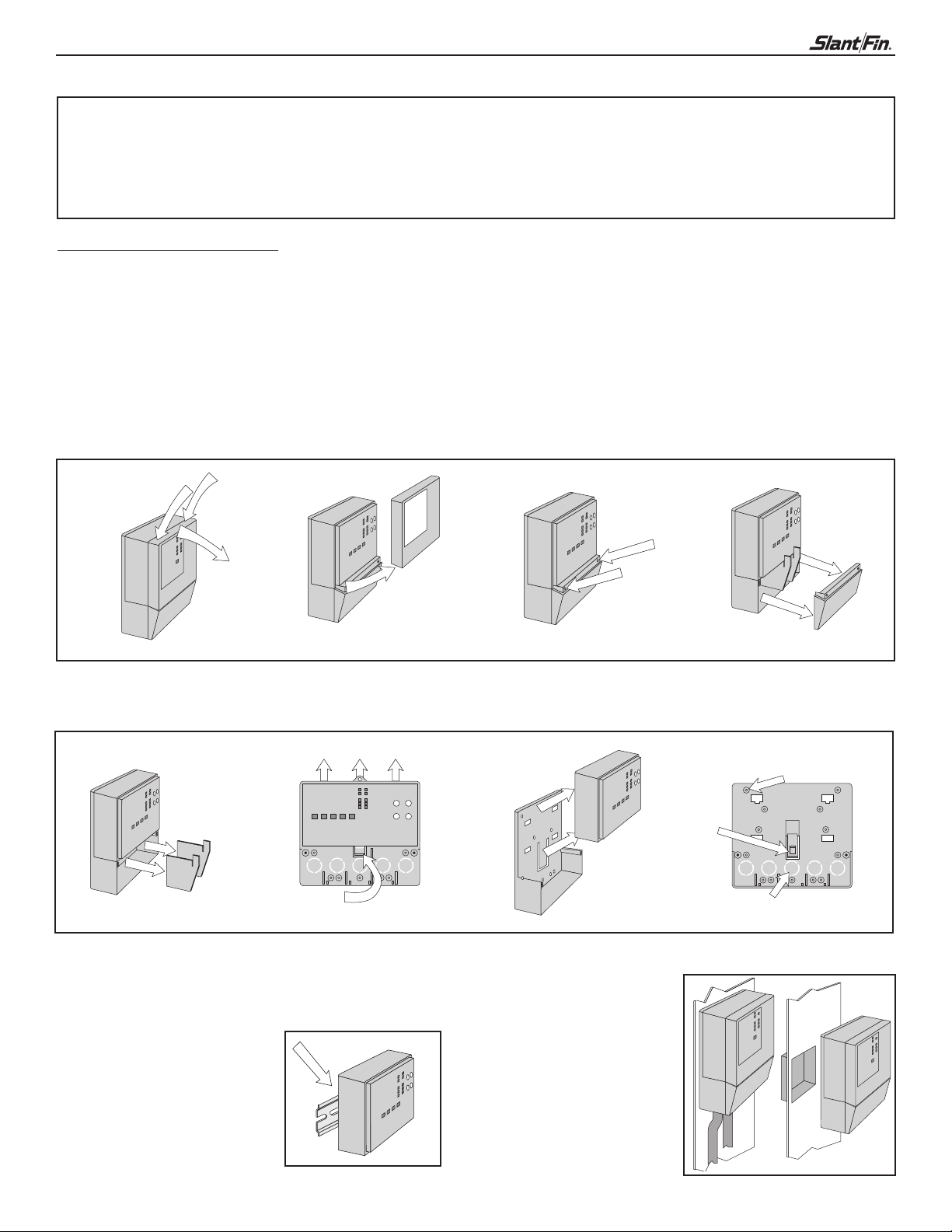
Press down at the fingertip
grips on top of the front cover
and pull out and down.
Remove the safety dividers
from the wiring chamber by
pulling them straight out of their
grooves.
The control can be mounted on
a standard DIN rail. First
remove the control from its
base and then, using the hooks
and spring clip on the back of
the control, mount it onto the
DIN rail. This will be a popular
option for those who prefer to
mount the control inside a larger electrical panel.
Lift the front cover up and away
from the control.
Press the control release clip
on the base inside the wiring
chamber and slide the control
upwards.
Loosen the screws at the front
of the wiring cover.
The control lifts up and away from
the base.
The wiring can enter the bottom or
the back of the enclosure. Knockouts provided in the base allow the
wiring to be run in conduit up to the
enclosure. The base also has holes
that line up with the mounting holes
of most common electrical boxes.
The wiring cover pulls straight
out from the wiring chamber.
The base is ready for mounting.
Page 3
SC-9 Controller 3
INSTALLING THE SENSORS
OUTDOOR SENSOR SLANT/FIN P/N 339070
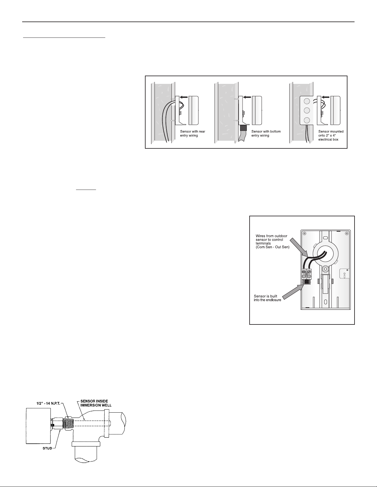
MOUNTING THE SENSOR
Note: The temperature sensor (thermistor) is built into the enclosure.
• Remove the screw and pull the front cover
ff the sensor enclosure.
o
• The enclosure can either be mounted directly
onto a wall or a 2” x 4” electrical box.
When it is wall mounted, the wiring
should enter through the back or bottom
of the enclosure. Do not mount the enclosure
with the conduit knockout facing upwards
as rain could enter the enclosure and
damage the sensor.
• In order to prevent heat transmitted through the wall from affecting the sensor reading, it may be necessary to install and insulating
barrier behind the enclosure.
• The sensor should be mounted on a northern wall of the building. It should not be exposed to heat sources such as ventilation or
window openings. Caution
temperatures that are not high enough to meet the demand.
: If sunlight strikes the sensor enclosure or the surface area surrounding it, the system will provide water
• It should be installed at an elevation above the ground that will prevent accidental damage or tampering.
WIRING AND TESTING THE SENSOR
• Connect 18 AWG or similar wire to the two terminals provided in the enclosure and
run the wires from the sensor to the control. Do not run the wires close to and parallel
to telephone or power cables. If the sensor wires are located in an area with strong
sources of electromagnetic interference (EMI), shielded cable or twisted pair should be
used or the wires can be run in a grounded metal conduit. If using shielded cable, the
shield wire should be connected to the Com Sen terminal on the control and not to earth
ground.
• Follow the sensor testing instruction that follows and connect the wires to the control.
• Replace the front cover of the sensor enclosure.
UNIVERSAL SENSORS
MOUNTING THE SENSOR SF P/N 339071
Note: These sensors are designed to mount in an immersion well or on a pipe.
For example - If a sensor is mounted onto a 1” type L copper pipe, there is approximately an 8 second delay between a sudden change in
water temperature and the time the sensor measures the change. This delay increases considerably when steel pipe is used.
It is strongly recommended that an immersion well be used, especially when steel pipe of greater than 1-1/4” is used and also
when large diameter pipes are used and fluid stratification is probable.
Sensor Mounted In Immersion Well
SLANT/FIN P/N 410569
Page 4
4
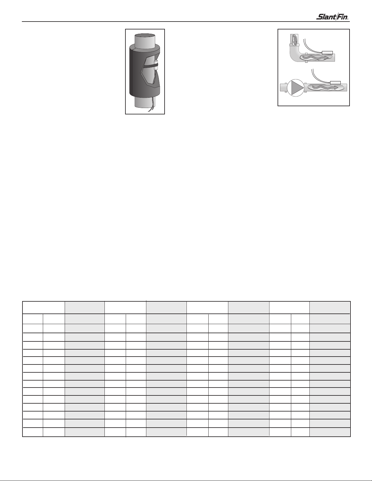
The Universal Sensor can be
strapped directly to the pipe using
the cable tie provided. Insulation
should be placed around the sensor
to reduce the effect of air currents on
the sensor measurement. The flat
ortion of the sensor should be mounted
p
against the pipe.
The Universal Sensor should be placed
downstream of a pump or after an elbow
or similar fitting. This is especially important if large diameter pipes are used as
the thermal stratification within the pipe
can result in erroneous sensor readings.
Proper sensor location requires that the
luid is thoroughly mixed within the pipe
f
before it reaches the sensor.
WIRING AND TESTING THE SENSOR
WARNING: Do not run sensor wires close to and parallel to telephone or power cables. If the sensor wires are located in an area with
strong sources of electromagnetic interference, shielded cable or twisted pair should be used or the wires can be run in a grounded metal
conduit. If using shielded cable, the shield wire should be connected to the Com Sen terminal on the control and not to earth ground.
• It is necessary to connect 18 AWG wire to the two sensor wires. Wire nuts can be used to hold the wires together.
• Follow the sensor testing instructions that follow and then connect the wires to the control.
SENSOR TESTING INSTRUCTIONS
A good quality test meter capable of measuring up to 5,000 kΩ (1 kΩ = 1000 Ω) is required to measure the sensor resistance. In addition
to this, the actual temperature must be measured with either a good quality digital thermometer, or if a thermometer is not available,
a second sensor can be placed alongside the one to be tested and the readings compared.
First measure the temperature using the thermometer and then measure the resistance of the sensor at the control. The wires from the
sensor must not be connected to the control while the test is performed. Using the chart below, estimate the temperature measured by
the sensor. The sensor and thermometer readings should be close. If the test meter reads a very high resistance, there may be a broken
wire, a poor wiring connection or a defective sensor. If the resistance is very low, the wiring may be shorted, there may be moisture in
the sensor or the sensor may be defective. To test for a defective sensor, measure the resistance directly at the sensor location.
Do not apply voltage to a sensor at any time as damage to the sensor may result.
Temperature Resistance Temperature Resistance Temperature Resistance Temperature Resistance
˚F ˚C ˚F ˚C ˚F ˚C ˚F ˚C
-50 -46 490,813 20 -7 46,218 90 32 7,334 160 71 1,689
-45 -43 405,710 25 -4 39,913 95 35 6,532 165 74 1,538
-40 -40 336,606 30 -1 34,558 100 38 5,828 170 77 1,403
-35 -37 280,279 35 2 29,996 105 41 5,210 175 79 1,281
-30 -34 234,196 40 4 26,099 110 43 4,665 180 82 1,172
-25 -32 196,358 45 7 22,763 115 46 4,184 185 85 1,073
-20 -29 165,180 50 10 19,900 120 49 3,760 190 88 983
-15 -26 139,402 55 13 17,436 125 52 3,383 195 91 903
-10 -23 118,018 60 16 15,311 130 54 3,050 200 93 829
-5 -21 100,221 65 18 13,474 135 57 2,754 205 96 763
0 -18 85,362 70 21 11,883 140 60 2,490 210 99 703
5 -15 72,918 75 24 10,501 145 63 2,255 215 102 648
10 -12 62,465 80 27 9,299 150 66 2,045 220 104 598
15 -9 53,658 85 29 8,250 155 68 1,857 225 107 553
Page 5
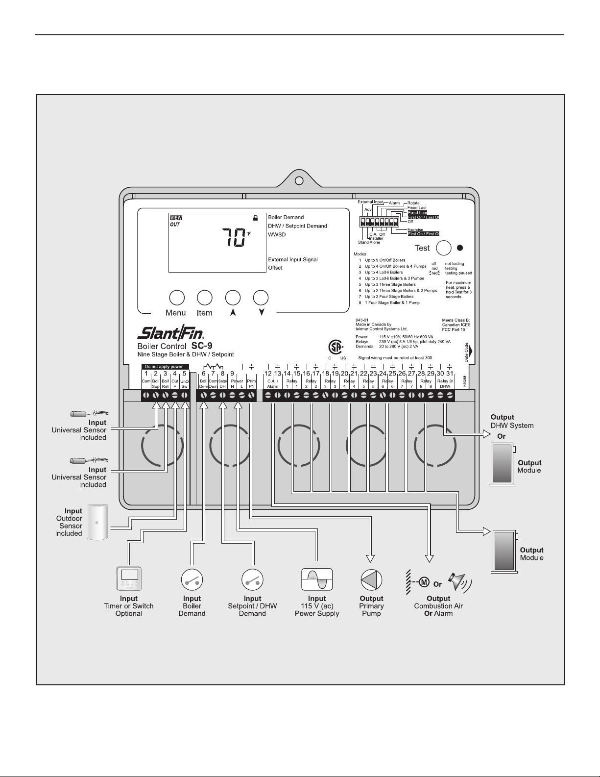
SC-9 Controller 5
Page 6
6
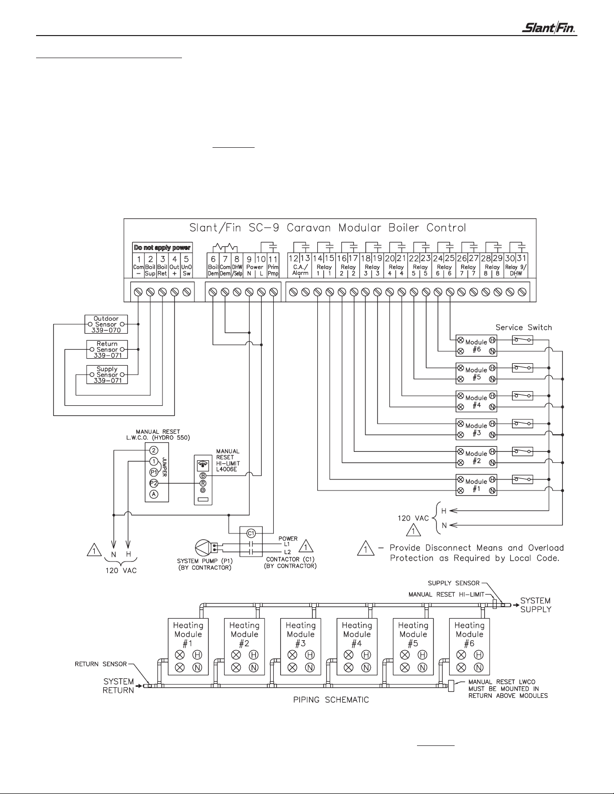
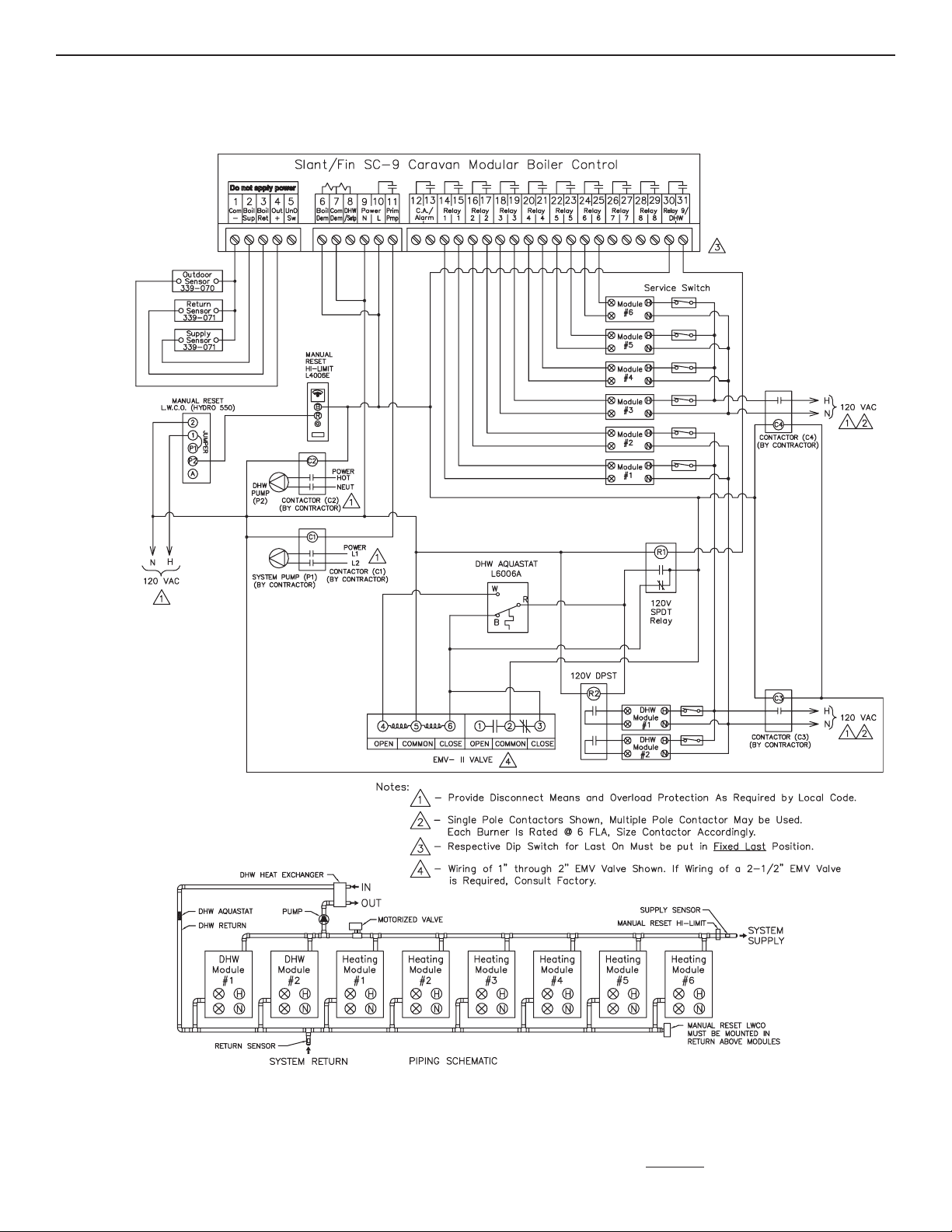
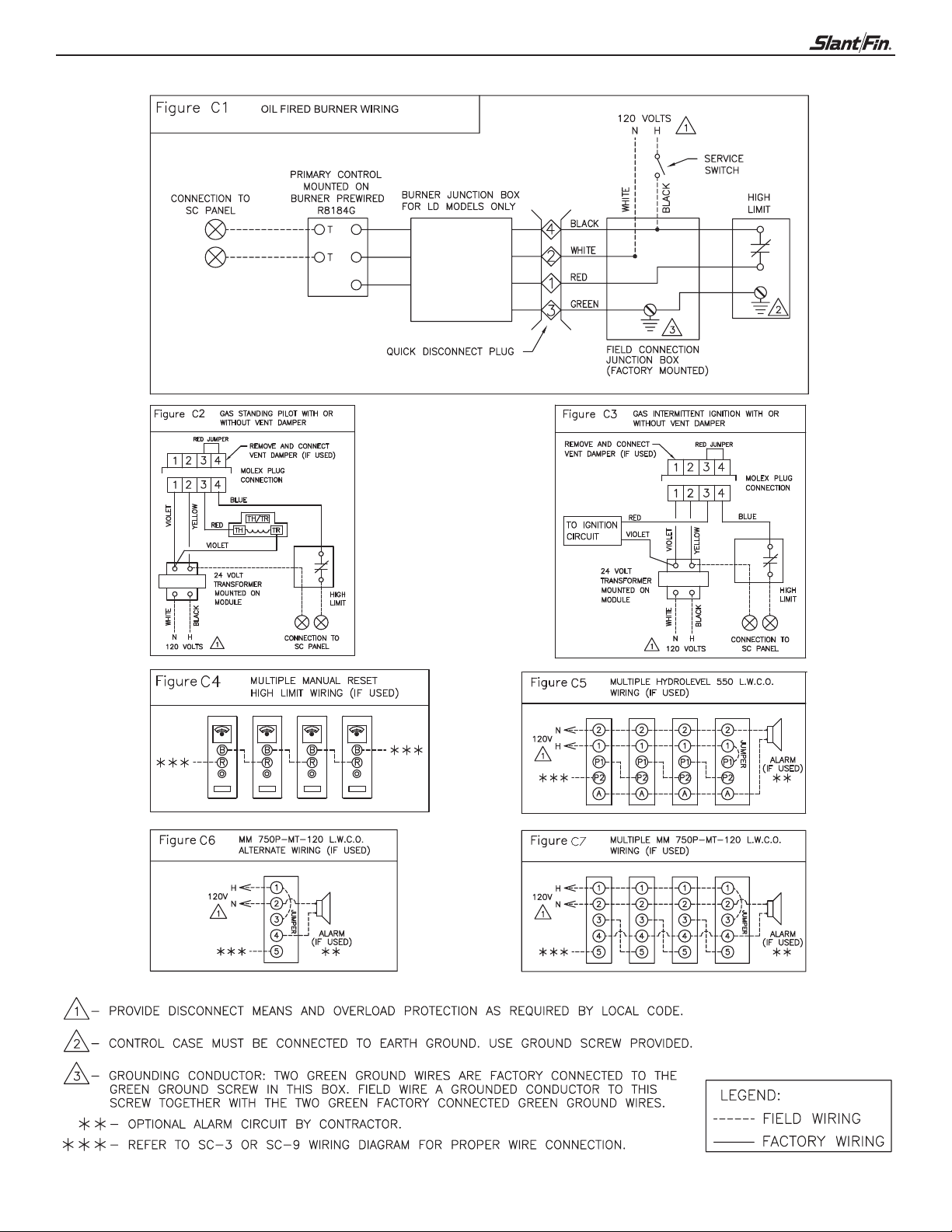
WIRING THE SYSTEM
Use one of the following wiring diagrams to wire your system, along with the appropriate diagram on page 10.
1. Gas fired - space heating only
. Gas fired - space heating with DHW
2
3. Oil fired - space heating only
4. Oil fired - space heating with DHW
n page 10 to wire the control
f using MM 750P-MT120 L.W.C.O. use Figure C6
I
o
1. Gas fired - space heating only
NOTE: For boiler termination wiring at modules, see page 10
Page 7
SC-9 Controller 7
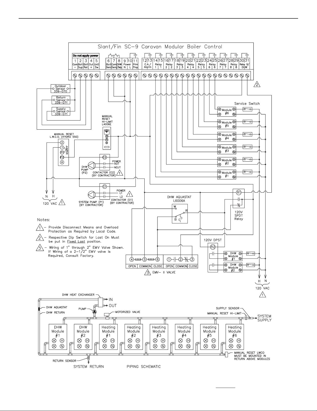
2. Gas fired - space heating with DHW
NOTE: For boiler termination wiring at modules, see page 10
Page 8
8
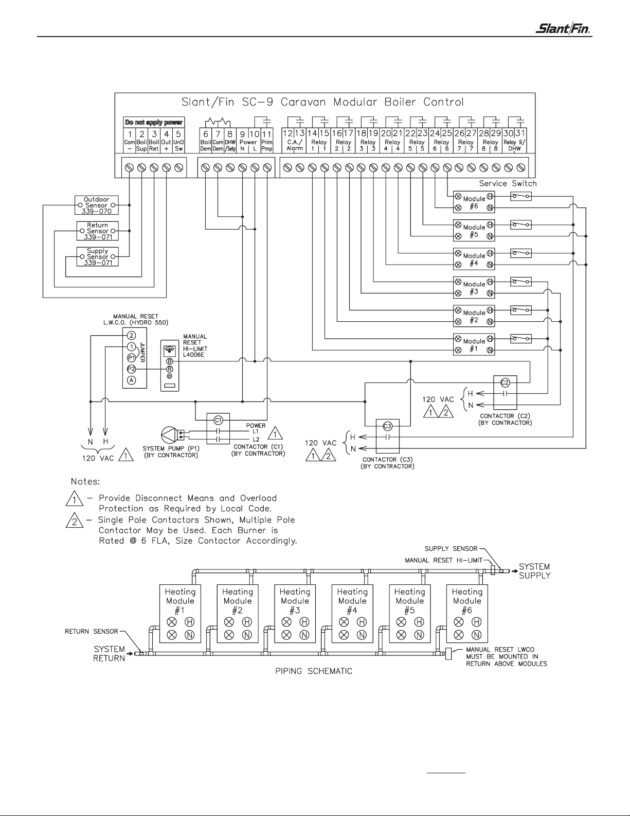
3. Oil fired - space heating only
NOTE: For boiler termination wiring at modules, see page 10
Page 9
SC-9 Controller 9
4. Oil fired - space heating with DHW
NOTE: For boiler termination wiring at modules, see page 10
Page 10
10
Page 11

SC-9 Controller 11
DISPLAY:
Symbol Description
Stage
Displays which stage relays are turned on.
Primary Pump
Displays when the primary pump relay is
turned on.
Combustion Air Damper
Displays when the Combustion Air Damper
relay is turned on
Delta T
The current difference between the supply
and return temperatures.
˚F, ˚C, min, hr
Units of measurement.
UnOccupied Schedule
Displays when the control is in UnOccupied
Mode.
Occupied Schedule
Displays when the control is in Occupied Mode.
Installer Access Level
Displays when the Installer/Advanced Dip
switch is set to Installer
Pointer
Displays the control operation as indicated by
the text.
Warning/Alarm
Displays when an error exists or the alarm relay
is turned on.
Page 12

12
User Interface
The control uses a Liquid Crystal Display (LCD) as the method of supplying information. You use the LCD in order to setup and monitor the
operation of your system. The control has four push buttons (Menu, Item, s,t) for selecting and adjusting settings. As you program your con-
trol, record your settings in the ADJUST menu table which is found in the second half of this brochure.
enu
M
All of the items displayed by the control are organized into two menus.
These menus are listed on the top left hand side of the display (Menu
Field). To select a menu, use the Menu button. By pressing and releasing
the Menu button, the display switches between the two menus. Once a menu
is selected, there will be a group of items that can be viewed within the menu.
Item
The abbreviated name of the selected item will be displayed in the item field
of the display. To view the next available item, press and release the Item
button. Once you have reached the last available item in a menu, pressing and
releasing the Item button will return the display to the first item in the selected
menu.
Adjust
To make an adjustment to a setting in the control, begin by selecting the
ADJUST menu using the Menu button. Then select the desired item using the
Item button. Finally, use the s, and / or t button to make the adjustment.
Additional information can be gained by observing the Status field of the LCD. The status field will indicate which of the control’s
outputs are currently active. Most symbols in the status field are only visible when the VIEW menu is selected.
SELECT SYSTEM TYPE:
A. Space Heating ONLY with Outdoor Reset (Most systems) . . . . . . . . . . . . . . . . . . . . . . Page 13
B. Space Heating ONLY with Setpoint Control . . . . . . . . . . . . . . . . . . . . . . . . . . . . . . . . . . Page 18
C. Space Heating with DHW with Outdoor Reset . . . . . . . . . . . . . . . . . . . . . . . . . . . . . . . . Page 19
D. Space Heating with DHW with Setpoint Control . . . . . . . . . . . . . . . . . . . . . . . . . . . . . . . Page 20
To set up the control, go to the appropriate page for your system.
If your system is different than the above, call the Slant/Fin technical services
group at 800-873-4346 to determine if the control can accommodate it.
Page 13

SC-9 Controller 13
A. SPACE HEATING ONLY WITH OUTDOOR RESET
CONTROL SET UP
DIP SWITCH SETTINGS:
General
The DIP switch settings on the control are very important and
should be set to the appropriate settings prior to making any
adjustments to the control through the User Interface. The DIP
switch settings change the items that are available to be viewed
and / or adjusted in the User Interface.
If a DIP switch is changed while the control is powered up, the
control responds to the change in setting by returning the display
to the VIEW menu.
External Input / Stand Alone
The External Input / Stand Alone DIP switch selects whether a
Slant/Fin Outdoor Sensor 339070 or an external 0-10 V (dc) input
signal is to be connected to the Com - and the Out + terminals
(1 and 4).
Set to Stand Alone
Advanced / Installer
The Adv / Installer DIP switch selects the access level of the
control. In the Installer access level, a limited number of items
may be viewed and / or adjusted. In the Advanced access level,
all items may be viewed and / or adjusted.
Set to Installer
Alarm / Combustion Air
The Alarm/Combustion Air DIP switch selects whether a
combustion air damper or alarm device is to be connected to the
C.A. / Alarm terminals (12 and 13).
Set to proper position. Ignore if neither is
present.
Page 14

14
SPACE HEATING ONLY WITH OUTDOOR RESET
Rotate / Off
The Rotate / Off DIP switch selects whether or not the control is to provide
Equal Run Time Rotation of the boiler stages. If the switch is set to Rotate,
the stages will be rotated accordingly. If the switch is set to Off, the firing
sequence is fixed starting with the lowest stage to the highest stage.
We recommend that it be set to Rotate for most
systems
Fixed Last / Off
he Fixed Last / Off DIP switch selects whether or not the last boiler is to be
T
included in the rotation sequence. If the DIP switch is set to Fixed Last, the
last boiler is always the last to fire. This DIP switch is only active when the
Rotate/Off DIP switch is set to Rotate.
We recommend that it be set to Off for most
systems.
Fixed Lead / Off
The Fixed Lead / Off DIP switch selects whether or not the first boiler is to
be included in the rotation sequence. If the DIP switch is set to Fixed Lead,
the first boiler is always the first to fire. This DIP switch is only active when
the Rotate/Off Dip switch is set to Rotate.
We recommend that it be set to Off for most
systems. Unusually long breeching from first boiler
to chimney may require that it be set to Fixed Lead.
First On / Last Off or First On / First Off
The First On / Last Off or First On / First Off DIP switch selects whether the
first boiler is the first to stage on and the last to stage off or the first to stage
on and the first to stage off. This DIP switch is only active when the Rotate /
Off DIP switch is set to Rotate and the Fixed Lead / Off DIP switch is set to
Fixed Lead.
We recommend that it be set to First On/First Off for
most systems.
Off / Exercise
The Off / Exercise DIP switch selects whether or not the control is to exercise the primary pump and boiler pumps. If the DIP switch is set to Exercise,
the pumps are operated for 10 seconds after every three days of inactivity.
We recommend that it be set to Exercise for most
systems.
Page 15

SC-9 Controller 15
SPACE HEATING ONLY WITH OUTDOOR RESET
THE CONTROL MUST BE ADJUSTED FOR YOUR APPLICATION.
IF ANY OF THE DEFAULT SETTINGS DO NOT SUIT YOUR APPLICATION, GO TO THE ADJUSTING SECTION
THAT FOLLOWS EACH FUNCTION AND WRITE IN THE DESIRED SETTING IN THE SQUARE BOX
ROVIDED FOR THAT FUNCTION. THEN PERFORM THE ADJUSTMENT AS LISTED.
P
HESE INSTRUCTIONS ARE WRITTEN WHERE EACH FUNCTION IS ADJUSTED IN A“STAND ALONE
T
HAT ONE FUNCTION ONLY
T
TALIC
ETTERSFOR EACH STEP AND PROGRAM THE CONTROL PROGRESSIVELY THROUGH EACH FUNCTION
I
L
IT IS BEST IF YOU TAKE A FEW MINUTES TO GO THROUGH THE ENTIRE LIST OF FUNCTIONS AND
ENTER ANY NEW SETTINGS THAT ARE APPROPRIATE FOR YOUR INSTALLATION
GO TO THE CONTROL AND ADJUST ONLY THOSE FUNCTIONS THAT HAVE A NEW SETTING LISTED.
F YOU WANT TO PROGRESSIVELY GO THROUGH EACH STEP
. I
ANNER MEANING YOU ARE PROGRAMMING
” M
UST SKIP THE INSTRUCTIONS WRITTEN IN
, J
.
. WHEN FINISHED,
PROGRAMMING FOR MOST APPLICATIONS
Programming sequence for most applications is covered in this section. This is followed when the Advanced/Installer
DIP switch is set to Installer.
Set Adv/Installer DIP switch to Installer
See Page 17 for instructions to program control using ˚C
Display Description
Room Occupied - The desired room air temperature during the occupied period.
Press the Menu button until ADJUST is visible on the top line of the display. Press the
Item button until ROOM appears above the temperature readout and OCC is flashing
below it. Use the up and down arrow buttons to change to the desired reading.
This item is only available if the External Input/Stand Alone DIP switch is set to
Stand Alone.
Range Available: 35˚ to 100˚F (2˚ to 38˚C)
Room Unoccupied - The desired room air temperature during the unoccupied period.
Press the
Item button until ROOM appears above the temperature readout and UNOCC is flashing
below it. Use the up and down arrow buttons to change to the desired reading.
This item is only available if the External Input/Stand Alone DIP switch is set to
Stand Alone.
Range Available: 35˚ to 100˚F (2˚ to 38˚C)
Boiler 1 - Selects whether or not module 1 is operational - Au (auto) or OFF
DO NOT CHANGE
Press the
Item button until BOIL to the left of, and above Au and 1 is below it. Use the up and down
arrow buttons to change setting. However for the setting of Au should be retained, do not
change to OFF.
Menu button until ADJUST is visible on the top line of the display. Press the
Menu button until ADJUST is visible on the top line of the display. Press
Default
Setting
70˚F
(21˚C)
65˚F
(18.5˚C)
Au
New
Setting
Page 16

16
OUT
DSGN
SPACE HEATING ONLY WITH OUTDOOR RESET
Display Description
Boiler 2 - Selects whether or not module 2 is operational - Au (auto) or OFF
DO NOT CHANGE
Press the
Item button until BOIL to the left of, and above Au and 2 is below it. Use the up and down
rrow buttons to change setting. However, the setting of Au should be retained, do not
a
change to OFF.
Boiler 3 - Selects whether or not module 3 is operational - Au (auto) or OFF
If you do not have 3 or more boiler modules
Press the
Item button until BOIL to the left of, and above Au and 3 is below it. Use the up and down
arrow buttons to change to OFF.
Boiler 4 - Selects whether or not module 4 is operational - Au (auto) or OFF
If you do not have 4 or more boiler modules
Press the
Item button until BOIL to the left of, and above Au and 4 is below it. Use the up and down
arrow buttons to change to OFF.
Boiler 5 - Selects whether or not module 5 is operational - Au (auto) or OFF
If you do not have 5 or more boiler modules
Press the
Item button until BOIL to the left of, and above Au and 5 is below it. Use the up and down
arrow buttons to change to OFF.
Menu button until ADJUST is visible on the top line of display. Press the
Menu button until ADJUST is visible on the top line of the display. Press the
Menu button until ADJUST is visible on the top line of the display. Press the
Menu button until ADJUST is visible on the top line of the display. Press the
Default
Setting
Au
Au
Au
Au
New
Setting
Boiler 6 - Selects whether or not module 6 is operational - Au (auto) or OFF
If you do not have 6 or more boiler modules
Press the
Item button until BOIL to the left of, and above Au and 6 is below it. Use the up and down
arrow buttons to change to OFF.
Boiler 7 - Selects whether or not module 7 is operational - Au (auto) or OFF
If you do not have 7 or more boiler modules
Press the
Item button until BOIL to the left of, and above Au and 7 is below it. Use the up and down
arrow buttons to change to OFF.
Boiler 8 - Selects whether or not module 8 is operational - Au (auto) or OFF
If you do not have 8 or more boiler modules
Press the
Item button until BOIL to the left of, and above Au and 8 is below it. Use the up and down
arrow buttons to change to OFF.
Boiler 9 - Selects whether or not module 9 is operational - Au (auto) or OFF
If you do not have 9 or more boiler modules
Press the
Item button until BOIL to the left of, and above Au and 9 is below it. Use the up and down
arrow buttons to change to OFF.
Outdoor design - The design outdoor temperature used in the heat loss calculations for
the heating system.
Menu button until ADJUST is visible on the top line of the display. Press the
Menu button until ADJUST is visible on the top line of the display. Press the
Menu button until ADJUST is visible on the top line of the display. Press the
Menu button until ADJUST is visible on the top line of the display. Press the
Au
Au
Au
Au
10˚F
Press the
Item button until OUT and DSGN appear. Use the up and down arrow buttons to change
to the desired setting.
Range Available: -60˚ to 45˚F (-51˚ to 7˚C)
Menu button until ADJUST is visible on the top line of the display. Press the
(-12˚C)
Page 17

SC-9 Controller 17
SPACE HEATING ONLY WITH OUTDOOR RESET
efault
Display Description
Boiler Mass - This inputs the thermal mass characteristics of the boiler modules.
ress the
P
Item button until BOIL is below ADJUST and MASS is to the right of ADJUST. Default is
2 with 1 being low mass and 3 being high mass. For Slant/Fin boilers we recommend you
retain the default setting of 2.
WWSD Occupied - The systems warm weather shut down temperature during the
occupied period.
enu button until ADJUST is visible on the top line of the display.Press the
M
D
Setting
2
70˚F
Press the
Item button until OCC appears. Use the up and down arrow buttons to change to the
desired temperature.
Range Available: 35˚ to 100˚F (2˚ to 38˚C or OFF)
Units - The units of measure that all of the temperatures are to be displayed by the control
Press the
Item button until ˚F or ˚C appears. Use the up and down arrow buttons to change to the
desired setting - ˚F or ˚C
NOTE: When you press ITEM button again you will go to the beginning of the sequence
Menu button until ADJUST is visible on the top line of the display. Press the
Menu button until ADJUST is visible on the top line of the display. Press the
(21˚C)
˚F
ew
N
Setting
Listed below are additional settings that are frequently changed from the factory default setting to a new
setting. These adjustments are made with the Installer/Adv DIP
switch in the Adv setting. You will
progress through a series of steps before you arrive at the steps that you want to adjust. Please be
careful and do not change the settings on any of the series of steps you pass through. If you do make a
mistake and change the setting on any of these steps we have listed the factory default settings in the
back of this manual. You can adjust that step accordingly.
Display Description
Boiler Design - The design supply water temperature used in the design of the system.
Move the Adv / Installer DIP
button until ADJUST is visible on the top line of the display. Press the Item button until
BOIL-DSGN appears. Use the up and down arrow buttons to change to the desired
temperature. Move the Adv / Installer DIP
Range Available: 70˚ to 220˚F
Boiler Maximum - The maximum allowed boiler target temperature
Move the Adv / Installer DIP
button until ADJUST is visible on the top line of the display. Press the Item button until
BOIL-MAX appears. Use the up and down arrow buttons to change to the desired
temperature. Move the Adv / Installer DIP
Range Available: 120˚ to 225˚F or OFF
switch to the Adv position temporarily. Press the Menu
switch back to the Installer position.
switch to the Adv position temporarily. Press the Menu
switch back to the Installer position.
Default
Setting
180˚F
(82˚C)
200˚F
(93.5˚C)
New
Setting
Page 18

18
B. SPACE HEATING ONLY WITH SETPOINT CONTROL
DIP SWITCH SETTINGS:
General
he DIP switch settings on the control are very important and
T
should be set to the appropriate settings prior to making any
adjustments to the control through the User Interface. The DIP
switch settings change the items that are available to be viewed
and / or adjusted in the User Interface.
If a DIP switch is changed while the control is powered up, the
control responds to the change in setting by returning the display
to the VIEW menu.
With the exception of Adv / Installer DIP switch, the DIP switch
settings are the same as in Section A “Space Heating with Outdoor
Reset”.
STEP 1: With the exception of Adv / Installer DIP switch, all DIP switches should be set the same
as in Section A, page 13, - “SPACE HEATING WITH OUTDOOR RESET”.
STEP 2: The following adjustments should be done after you have programmed Section A -
“SPACE HEATING WITH OUTDOOR RESET”.
STEP 3: Program the following steps.
Display Description
Default
Setting
XOutdoor Design - For Setpoint Operation MUST be adjusted.
Move the Adv / Installer DIP
visible on the top line of the display. Press the Item button until OUT and DSGN appear.
Use the up and down arrow buttons to change the setting to 45˚F.
Range Available: -60˚ to 45˚F (-51˚ to 7˚C)
Boiler Design - The design supply water temperature used in the design of the system.
Set at least 10˚F above Boiler Minimum
Move the Adv / Installer DIP
button until ADJUST is visible on the top line of the display. Press the Item button until
BOIL-DSGN appears. Use the up and down arrow buttons to change to the desired
temperature. Move the Adv / Installer DIP
Range Available: 70˚ to 220˚F (21˚ to 104˚C)
Boiler Minimum - The Setpoint Control Temperature
Move the Adv / Installer DIP
button until ADJUST is visible on the top line of the display. Press the Item button until
BOIL MIN appears. Use the up and down arrow buttons to change to the DESIRED
SETPOINT temperature - 140˚F or more. Move the Adv / Installer DIP
Installer position.
Range Available: OFF, 80˚ - 180˚F (OFF, 27˚ - 82˚C)
Boiler Maximum - The maximum allowed boiler target temperature. Set at least 10˚F
above Boiler Design
Move the Adv / Installer DIP
button until ADJUST is visible on the top line of the display. Press the Item button until
BOIL-MAX appears. Use the up and down arrow buttons to change to the desired
temperature. Move the Adv / Installer DIP
Range Available: 120˚ to 225˚F or OFF (49˚ to 107˚C or OFF)
switch to Installer. Press the Menu button until ADJUST is
setting.
switch to the Adv position temporarily. Press the Menu
switch back to the Installer position.
switch to the Adv position temporarily. Press the Menu
switch back to the
setting.
switch to the Adv position temporarily. Press the Menu
switch back to the Installer position.
10˚F
(12˚C)
180˚F
(82˚C)
140˚F
(60˚C)
200˚F
(93.5˚C)
New
Setting
45˚F
(7˚C)
Please contact the Slant/Fin Technical Services Department if you need another way.
Please note that other ways may require additional relays for circulators.
Slant/Fin Technical Service 1-800-873-4346
Page 19

SC-9 Controller 19
C. SPACE HEATING WITH DHW WITH OUTDOOR RESET
ONTROL SET UP
C
DIP SWITCH SETTINGS:
General
The DIP switch settings on the control are very important and
should be set to the appropriate settings prior to making any
adjustments to the control through the User Interface. The DIP
switch settings change the items that are available to be viewed
and / or adjusted in the User Interface.
If a DIP switch is changed while the control is powered up, the
control responds to the change in setting by returning the display
to the VIEW menu.
With the exception of Rotate / OFF and Fixed Last / OFF DIP
switch. The DIP switch settings are the same as in System type A
“Space Heating Only with Outdoor Reset”.
STEP 1: Set Rotate / OFF and Fixed Last / OFF DIP switches as follows.
Rotate / Off
The Rotate / Off DIP switch selects whether or not the control is to provide
Equal Run Time Rotation of the boiler stages. If the switch is set to Rotate,
the stages will be rotated accordingly. If the switch is set to Off, the firing
sequence is fixed starting with the lowest stage to the highest stage.
Set to rotate
Fixed Last / Off
The Fixed Last / Off DIP switch selects whether or not the last boiler is to be
included in the rotation sequence. If the DIP switch is set to Fixed Last, the
last boiler is always the last to fire. This DIP switch is only active when the
Rotate/Off DIP switch is set to Rotate.
Must be set to fixed last.
STEP 2: Program the control following programming steps in Section A, page 13, “Space Heating
with Outdoor Reset”.
When the WWSD (Warm Weather Shut Down) temperature is reached the operation of
DHW is still active. Control of the DHW modules during a demand for DHW by-passes the
SC-9 Control.
Page 20

20
D. SPACE HEATING WITH DHW WITH SETPOINT CONTROL
CONTROL SET UP
DIP SWITCH SETTINGS:
General
The DIP switch settings on the control are very important and
hould be set to the appropriate settings prior to making any
s
adjustments to the control through the User Interface. The DIP
switch settings change the items that are available to be viewed
and / or adjusted in the User Interface.
If a DIP switch is changed while the control is powered up, the
control responds to the change in setting by returning the display
to the VIEW menu.
With the exception of Adv / Installer, Rotate / OFF and
Fixed Last / OFF DIP switches, the DIP switch settings are the
same as in Section A “Space Heating with Outdoor Reset”.
STEP 1: Set Advanced / Installer, Rotate / OFF and Fixed Last / OFF DIP switches as follows.
Advanced / Installer
The Adv / Installer DIP switch selects the access level of the control. In the
Installer access level, a limited number of items may be viewed and / or
adjusted. In the Advanced access level, all items may be viewed and / or
adjusted.
Set to Adv
Rotate / Off
The Rotate / Off DIP switch selects whether or not the control is to provide
Equal Run Time Rotation of the boiler stages. If the switch is set to Rotate,
the stages will be rotated accordingly. If the switch is set to Off, the firing
sequence is fixed starting with the lowest stage to the highest stage.
Set to Rotate
Fixed Last / Off
The Fixed Last / Off DIP switch selects whether or not the last boiler is to be
included in the rotation sequence. If the DIP switch is set to Fixed Last, the
last boiler is always the last to fire. This DIP switch is only active when the
Rotate/Off DIP switch is set to Rotate.
Must be set to fix last.
Page 21

SC-9 Controller 21
PACE HEATING WITH DHW WITH SETPOINT CONTROL
S
STEP 2: Program the following steps.
isplay
D
escription
D
XOutdoor Design - For Setpoint Operation MUST be adjusted.
Move the Adv / Installer DIP
visible on the top line of the display. Press the Item button until OUT and DSGN appear.
Use the up and down arrow buttons to change the setting to 45˚F.
ange Available: -60˚ to 45˚F (-51˚ to 7˚C)
R
Boiler Design - The design supply water temperature used in the design of the system.
Set at least 10˚F above Boiler Minimum
Move the Adv / Installer DIP
button until ADJUST is visible on the top line of the display. Press the Item button until
BOIL-DSGN appears. Use the up and down arrow buttons to change to the desired
temperature. Move the Adv / Installer DIP
Range Available: 70˚ to 220˚F (21˚ to 104˚C)
Boiler Minimum - The Setpoint Control Temperature
Move the Adv / Installer DIP
button until ADJUST is visible on the top line of the display. Press the Item button until
BOIL MIN appears. Use the up and down arrow buttons to change to the DESIRED
SETPOINT temperature - 140˚F or more. Move the Adv / Installer DIP
Installer position.
Range Available: OFF, 80˚ - 180˚F (OFF, 27˚ - 82˚C)
switch to Installer. Press the Menu button until ADJUST is
setting.
switch to the Adv position temporarily. Press the Menu
switch back to the Installer position.
switch to the Adv position temporarily. Press the Menu
switch back to the
Default
Setting
10˚F
(12˚C)
180˚F
(82˚C)
140˚F
(60˚C)
New
Setting
45˚F
(7˚C)
Boiler Maximum - The maximum allowed boiler target temperature. Set at least 10˚F
above Boiler Design
Move the Adv / Installer DIP
button until ADJUST is visible on the top line of the display. Press the Item button until
BOIL-MAX appears. Use the up and down arrow buttons to change to the desired
temperature. Move the Adv / Installer DIP
Range Available: 120˚ to 225˚F or OFF (49˚ to 107˚C or OFF)
Please contact the Slant/Fin Technical Services Department if you need another way.
Please note that other ways may require additional relays for circulators.
When the WWSD (Warm Weather Shutdown) temperature is reached the operation or DHW is still active. Control of the DHW
modules during a demand for DHW by-passes the SC-9 control.
setting.
switch to the Adv position temporarily. Press the Menu
switch back to the Installer position.
200˚F
(93.5˚C)
Slant/Fin Technical Service 1-800-873-4346
Page 22

22
SPACE HEATING WITH DHW WITH SETPOINT CONTROL
Detailed information for ADV mode of ADV / Installer DIP switch
The SC-9 control has many features and some of these features are rarely used. These features are accessed and their settings changed
when the Adv / Installer DIP switch is in the Adv position. As a reference, listed below is the list of all the features accessed with the DIP
switch in Adv position. These are listed in sequential order as accessed in the SC-9 control.
STEP 1: Set Adv / Installer DIP switch in Adv position.
STEP 2: Press Mode button once.
STEP 3: Press Item button repeatedly through the steps in sequence listed below.
Display Description
Room Occupied - The desired room air temperature during the occupied period.
This item is only available if the External Input/Stand Alone DIP switch is set to
Stand Alone.
Range Available: 35˚ to 100˚F (2˚ to 38˚C)
Room Unoccupied - The desired room air temperature during the unoccupied period.
This item is only available if the External Input/Stand Alone DIP switch is set to
Stand Alone.
Range Available: 35˚ to 100˚F (2˚ to 38˚C)
Boost - The amount of morning boost.
This item is only available if the External Input/Stand Alone DIP switch is set to
Stand Alone.
Range Available: OFF, 0:20 to 8:00 hr (5 minute increment)
Default
Setting
70˚F
(21˚C)
65˚F
(18.5˚C)
OFF
New
Setting
Mode - Selects the staging mode of operation.
Keep on 1
Page 23

SC-9 Controller 23
SPACE HEATING WITH DHW WITH SETPOINT CONTROL
Display Description
Boiler 1 - Selects whether or not boiler 1 is operational
This item is available in all modes.
Range Available: Au (Auto), OFF
Boiler 2 - Selects whether or not boiler 2 is operational
his item is available in modes 1 to 7.
T
Range Available: Au (Auto), OFF
Boiler 3 - Selects whether or not boiler 3 is operational
This item is available in modes 1 to 5.
Range Available: Au (Auto), OFF
Boiler 4 - Selects whether or not boiler 4 is operational
This item is available in modes 1 to 3.
Range Available: Au (Auto), OFF
Default
Setting
Au
Au
Au
Au
New
Setting
Boiler 5 - Selects whether or not boiler 5 is operational
This item is available in mode 1.
Range Available: Au (Auto), OFF
Boiler 6 - Selects whether or not boiler 6 is operational
This item is available in mode 1.
Range Available: Au (Auto), OFF
Boiler 7 - Selects whether or not boiler 7 is operational
This item is available in mode 1.
Range Available: Au (Auto), OFF
Boiler 8- Selects whether or not boiler 8 is operational
This item is available in mode 1.
Range Available: Au (Auto), OFF
Boiler 9- Selects whether or not boiler 9 is operational
This item is available in mode 1.
Range Available: Au (Auto), OFF
Au
Au
Au
Au
Au
Page 24

24
SPACE HEATING WITH DHW WITH SETPOINT CONTROL
Display Description
Outdoor Design - The design outdoor air temperature used in the heat loss
calculations for the heating system.
This item is only available if the External Input/Stand Alone DIP switch is set to
Stand Alone.
ange Available: -60˚ to 45˚F (-51˚ to 7˚C)
R
Boiler Indoor - The design indoor air temperature used in the heat loss calculation for
the heating system.
This item is only available if the External Input/Stand Alone DIP switch is set to
Stand Alone.
Range Available: 35˚ to 100˚F (2˚ to 38˚C)
Boiler Design - The design supply water temperature used in the heat loss
calculations for the heating system.
This item is only available if the External Input/Stand Alone DIP switch is set to
Stand Alone.
Range Available: 70˚ to 220˚F (21˚ to 104˚C)
efault
D
Setting
10˚F
(12˚C)
70˚F
(21˚C)
180˚F
(82˚C)
ew
N
Setting
Boiler Minimum - The minimum allowed boiler target temperature
Range Available: OFF, 80˚ to 180˚F (OFF, 27˚ to 82˚C)
Boiler Maximum - The maximum allowed boiler target temperature
Range Available: 120˚ to 225˚F, OFF (49˚ to 107˚C, OFF)
Fire Delay 1 - The time delay the control can expect between the time that the relay
contact closes to fire the first stage of the boiler and the burner actually fires.
Range Available: 0:00 to 3:00 minutes (1 sec increment)
Combustion Air Damper Delay - The time allowed for the combustion air damper to
open before the first stage is fired.
This item is only available if the Alarm / C.A. DIP switch is set to C.A.
Range Available: 0:00 to 3:00 minutes (1 sec increment)
140˚F
(60˚C)
200˚F
(93.5˚C)
0:10
min
1:00
min
Boil Mass - The thermal mass characteristics of the boilers that are being used.
Range Available: 1 (Lo), 2 (Med), 3 (Hi)
2
Page 25

SC-9 Controller 25
SPACE HEATING WITH DHW WITH SETPOINT CONTROL
Display Description
Stage Delay - The minimum time delay between the operation of stages.
Range Available: Au (Auto), 0:30 to 19:55 min (5 second increment)
Boiler Differential - The temperature differential that the control is to use when it is
operating the boiler(s)
Range Available: Au (Auto), 2˚ to 42˚F (Au, 1˚ to 23˚C)
Mode - Please keep this setting on 1.
Failure to do so may cause the system pump to go off.
Range Available: 1, 2 or 3
Setpoint Occupied - The minimum supply temperature when a setpoint demand is
present during the Occupied period.
In this mode the control will not energize the system circulator if you have voltage
(between 24 and 230 volts AC) applied across terminals 7 and 8 on the control. These
are the Com Dem (common demand) and Setp (setpoint demand) terminals. DO NOT
apply voltage across these terminals. Please note we suggest you handle setpoint
applications as explained in sections B and D in this manual. Leave control set at its
default setting.
This item is only available if the External Input / Stand Alone DIP switch is set to
Stand Alone.
Range Available: OFF, 60˚ to 220˚F (OFF, 16 to 104˚C)
efault
D
Setting
Au
Au
1
180˚F
(82˚C)
ew
N
Setting
Setpoint Unoccupied - Selects whether or not a setpoint demand will be responded to
during the UnOccupied period.
In this mode the control will not energize the system circulator if you have voltage
(between 24 and 230 volts AC) applied across terminals 7 and 8 on the control. These
are the Com Dem (common demand) and Setp (setpoint demand) terminals. DO NOT
apply voltage across these terminals. Please note we suggest you handle setpoint
applications as explained in sections B and D in this manual. Leave control set at its
default setting.
This item is only available if the External Input / Stand Alone DIP switch is set to
Stand Alone.
Range Available: 35˚ to 100˚F, OFF (2˚ to 38˚C, OFF)
WWSD Occupied - The system’s warm weather shut down temperature during the
Occupied period.
This item is only available if the External Input / Stand Alone DIP switch is set to
Stand Alone.
Range Available: 35˚ to 100˚F, OFF (2˚ to 38˚C, OFF)
WWSD Unoccupied - The system’s warm weather shut down temperature during the
UnOccupied period.
This item is only available if the External Input / Stand Alone DIP switch is set to
Stand Alone.
Range Available: 35˚ to 100˚F, OFF (2˚ to 38˚C, OFF)
OFF
70˚F
(21˚C)
60˚F
(15.5˚C)
Page 26

26
SPACE HEATING WITH DHW WITH SETPOINT CONTROL
Display Description
rimary Pump Purge - The maximum length of time that the primary pump will
P
continue to operate after the boiler demand has been removed.
Range Available: OFF, 0:10 to 19:55 min (5 sec increment)
Units- The units of measure that all of the temperatures are to be displayed in by the
control.
Range Available: ˚F, ˚C
NOTE: When you press the ITEM button again you will go to the beginning of the sequence
efault
D
Setting
0:20
min
˚F
ew
N
Setting
Page 27

SC-9 Controller 27
VIEW THE PERFORMANCE
FUNCTION DESCRIPTION STEPS
OUTDOOR
BOILER SUPPLY
BOILER TARGET
BOILER RETURN
DELTA T
BOILER 1 HOUR
Current outdoor air temperature
as measured by the outdoor
ensor.
s
Current boiler supply water
temperature as measured by the
boiler supply sensor.
Boiler target temperature is the
temperature the control is trying
to maintain at the boiler supply
sensor.
Current boiler return water
temperature as measured by the
boiler return sensor.
Current difference in temperature
between the boiler supply sensor
and the boiler return sensor
temperatures.
The total running time of
module 1 since this item was
last cleared.
Press the Menu button until VIEW is visible on the top line of the display.
Press the Item button until OUT appears. Read the numeric display.
Press the Menu button until VIEW is visible on the top line of the display.
Press the Item button until BOIL SUP appears. Read the numeric display.
Move the Adv/ Installer DIP switch to the Adv position temporarily.
Press the Menu button until VIEW is visible on the top line of the display.
Press the Item button until BOIL TARG appears. Read the numeric display.
Move the Adv/ Installer DIP switch back to the Installer position.
Move the Adv/ Installer DIP switch to the Adv position temporarily.
Press the Menu button until VIEW is visible on the top line of the display.
Press the Item button until BOIL RET appears. Read the numeric display.
Move the Adv/ Installer DIP switch back to the Installer position.
A boiler return sensor must be installed to view this item.
Move the Adv/Installer DIP switch to the Adv position temporarily.
Press the Menu button until VIEW is visible on the top line of the display.
Press the Item button until ΔT appears. Read the numeric display. Move
the Adv/Installer DIP switch back to the Installer position.
A boiler return sensor must be installed to view this item
Move the Adv/Installer DIP switch to the Adv position temporarily.
Press the Menu button until VIEW is visible. Press the Item button until
BOIL appears on the second line of the display, and 1 in the lower right
section. Read the numeric display in hours. To clear this item back to 0,
press the Up and Down buttons simultaneously while viewing this item.
Move the Adv/Installer DIP switch back to the Installer position.
BOILER 2 HOURS
BOILER 3 HOURS
BOILER 4 HOURS
The total running time of
module 1 since this item was
last cleared.
The total running time of
module 1 since this item was
last cleared.
The total running time of
module 1 since this item was
last cleared.
Move the Adv/Installer DIP switch to the Adv position temporarily.
Press the Menu button until VIEW is visible. Press the Item button until
BOIL appears on the second line of the display, and 2 in the lower right
section. Read the numeric display in hours. To clear this item back to 0,
press the Up and Down buttons simultaneously while viewing this item.
Move the Adv/Installer DIP switch back to the Installer position.
Move the Adv/Installer DIP switch to the Adv position temporarily.
Press the Menu button until VIEW is visible. Press the Item button until
BOIL appears on the second line of the display, and 3 in the lower right
section. Read the numeric display in hours. To clear this item back to 0,
press the Up and Down buttons simultaneously while viewing this item.
Move the Adv/Installer DIP switch back to the Installer position.
Move the Adv/Installer DIP switch to the Adv position temporarily.
Press the Menu button until VIEW is visible. Press the Item button until
BOIL appears on the second line of the display, and 4 in the lower right
section. Read the numeric display in hours. To clear this item back to 0,
press the Up and Down buttons simultaneously while viewing this item.
Move the Adv/Installer DIP switch back to the Installer position.
Follow the above procedure for all remaining boiler stages
Page 28

28
USEFUL HINTS
Hint #1
Reloading Factory Defaults
o reload the factory defaults, power down the control for 10 seconds. Power up the control while simultaneously holding the Menu and
T
t buttons. The control will now display the E01 error message. To clear this error message, follow the procedure in the Error Message
section below.
The control was reloaded to factory default settings. However, the control will stop operation until all of the items in
the ADJUST menu of the control have been checked by the user or installer. After checking all items press MENU.
NOTE: The Installer / Adv DIP Switch must be set to Adv in order to clear the error.
Hint #2
Room Occupied Setting
Changing the Room Occupied setting will change the heating curve. If you want more heat you should increase this setting above 70˚F
(21˚C). If you want less heat you can decrease the setting below 70˚F (21˚C).
Page 29

SC-9 Controller 29
TESTING THE CONTROL
The control has a built-in test routine that is used to test the main
control functions. The control continually monitors the sensors and
displays an error message whenever a fault is found. See the following
ages for a list of the control’s error messages and possible causes.
p
When the Test button is pressed, the test light is turned on. The
individual outputs and relays are tested in the following test sequence.
Test Sequence
Each step in the test sequence lasts 10 seconds.
During the test routine, if a demand from the system is present, the test sequence may be paused by pressing the Test button. If the Test
button is not pressed again for 5 minutes while the test sequence is paused, the control exits the entire test routine. If the test sequence is
paused, the Test button can be pressed again to advance to the next step. This can also be used to rapidly advance through the test
sequence. To reach the desired step, repeatedly press and release the Test button until the appropriate device and segment in the display
turn on.
STEP 1: The primary pump is turned on and remains on for the entire test routine.
STEP 2: If the Alarm / C.A. DIP switch is set to Alarm, the Alarm contact is turned on for 10
seconds and then shuts off. If the Alarm / C.A. DIP switch is set to C.A., the Combustion
Air Damper contact is turned on and remains on for the entire test routine.
STEP 3: For each boiler that is set to Auto, the following test sequence is used. If the mode
indicates that a boiler pump is used, the boiler pump is turned on and remains on. Next,
the first stage of the boiler is turned on and remains on. If a second stage is present, the
second stage is turned on and remains on. If a third stage is present, the third stage is
turned on and remains on. If a fourth stage is present, the fourth stage is turned on. After
ten seconds, all stages and the boiler pump are turned off.
This step is repeated for each additional boiler that is set to Auto.
STEP 4: All contacts are turned off.
Page 30

30
Error Messages
The control was unable to read a piece of information stored in its memory. Because of this, the
control was required to reload the factory settings into all of the items in the ADJUST menu. The
control will stop operation until all of the items in the ADJUST menu of the control have been
checked by the user or installer.
ote: The Installer / Adv DIP Switch must be set to Adv in order to clear the error.
N
The control is no longer able to read the outdoor sensor due to a short circuit. In this case the
control assumes an outdoor temperature of 32˚F (0˚C) and continues operation. Locate and repair
the problem. To clear the error message from the control after the sensor has been repaired, press
either the Menu or Item button.
This error message only occurs if the External Input/Stand Alone DIP switch is set to Stand Alone.
The control is no longer able to read the outdoor sensor due to an open circuit. In this case the
control assumes an outdoor temperature of 32˚F (0˚C) and continues operation. Locate and repair
the problem. To clear the error message from the control after the sensor has been repaired, press
either the Menu or Item button.
This error message only occurs if the External Input/Stand Alone DIP switch is set to Stand Alone.
The control is no longer able to read the boiler supply sensor due to a short circuit. The control will
not operate the boiler(s) until the sensor is repaired. Locate and repair the problem. To clear the
error message from the control after the sensor has been repaired, press either the Menu or Item
button.
The control is no longer able to read the boiler supply sensor due to an open circuit. The control
will not operate the boiler(s) until the sensor is repaired. Locate and repair the problem. To clear
the error message from the control after the sensor has been repaired, press either the Menu or
Item button.
The control is no longer able to read the boiler return sensor due to a short circuit. The control will
continue to operate normally. Locate and repair the problem. To clear the error message from the
control after the sensor has been repaired, press either the Menu or Item button.
The control is no longer able to read the boiler return sensor due to an open circuit. The control
will continue to operate normally. Locate and repair the problem. To clear the error message from
the control after the sensor has been repaired, press either the Menu or Item button.
If the boiler return sensor was deliberately removed from the control, remove power from the control and repower the control to clear the error message.
Page 31

SC-9 Controller 31
SC-9
Technical Data
Boiler Control SC-9 - Nine Stage Boiler & Setpoint
Control –– Microprocessor PID control; This is not a safety (limit) control.
Packaged weight –– 3.3 lb. (1500g), Enclosure A, blue modified PPO plastic
Dimensions –– 6-5/8” H x 7-9/16” W x 2-13/16” D (170 x 193 x 72 mm)
Approvals –– CSA C US, meets ICES & FCC regulations for EMI/RFI.
Ambient conditions –– Indoor use only, 30 to 120˚F (0 to 50˚C), <95% RH non-condensing.
Power Supply –– 115 V (ac) ± 10% 50/60 Hz 600 VA
Relay capacity –– 230 V (ac) ± 5 A 1/3 hp pilot duty 230 VA
Demands –– 20 to 260 V (ac) 2 VA
Sensors included –– NTC thermistor, 10 k Ω @ 77˚F (25˚C ± 0.2˚C) ß=3892
Outdoor Sensor 339070 and Universal Sensor 339071.
The installer must ensure that this control and its wiring are isolated and/or shielded from strong sources of electromagnetic noise.
Conversely, this Class B digital apparatus complies with Part 15 of the FCC Rules and meets all requirements of the Canadian
Interference-Causing Equipment Regulations. However, if this control does cause harmful interference to radio or television reception,
which is determined by turning the control off and on, the user is encouraged to try to correct the interference by re-orientating or relocating the receiving antenna, relocating the receiver with respect to this control, and/or connecting the control to a different circuit from
that to which the receiver is connected.
Caution: The nonmetallic enclosure does not provide grounding between conduit connections. Use grounding type bushings and jumper wires.
Page 32

LISTING OF ALL FACTORY DEFAULT SETTINGS
FUNCTION
ROOM OCC
ROOM UN OCC
BST
MODE
BOIL 1
BOIL 2
BOIL 3
BOIL 4
BOIL 5
BOIL 6
BOIL 7
BOIL 8
DEFAULT
SETTING
70˚F (21˚C)
65˚F (18˚C)
OFF
1
Au
Au
Au
Au
Au
Au
Au
Au
FUNCTION
BOIL MIN
BOIL MAX
F DLY 1
DLY
BOIL MASS
STG DLY
BOIL DIFF
MODE SETP
SETP OCC
SETP UNOCC
OCC WWSD
UN OCC WWSD
PURGE
DEFAULT
SETTING
140˚F (60˚C)
200˚F (93˚C)
0:10 Min
1:00 Min
2
Au
Au
1
180˚ (82˚C)
OFF
70˚ (21˚C)
60˚ (16˚C)
0:20 Min
BOIL 9
OUT DSGN
BOIL INDR
Au
10˚F (-12˚C)
70˚F (21˚C)
˚F or ˚C
PDF format instructions
A pdf version of this document is available.
Request Pub. No. SC9-40 (pdf)
by e-mail to: marketing@slantfin.com
SLANT/FIN CORPORATION, Greenvale, N.Y. 11548 • Phone: (516) 484-2600
FAX: (516) 484-5921 • Canada: Slant/Fin LTD/LTEE, Mississauga, Ontario
˚F
www.slantfin.com
 Loading...