

Page 1
A major answer to the changing heating-fuel situation
HOT WATER MODELS IN 9 SIZES
8 kw (27,301 Btuh) to 40 kw (136,506 Btuh)
Before purchasing this appliance,
read important energy cost and
efficiency information available
from your contractor.
Page 2
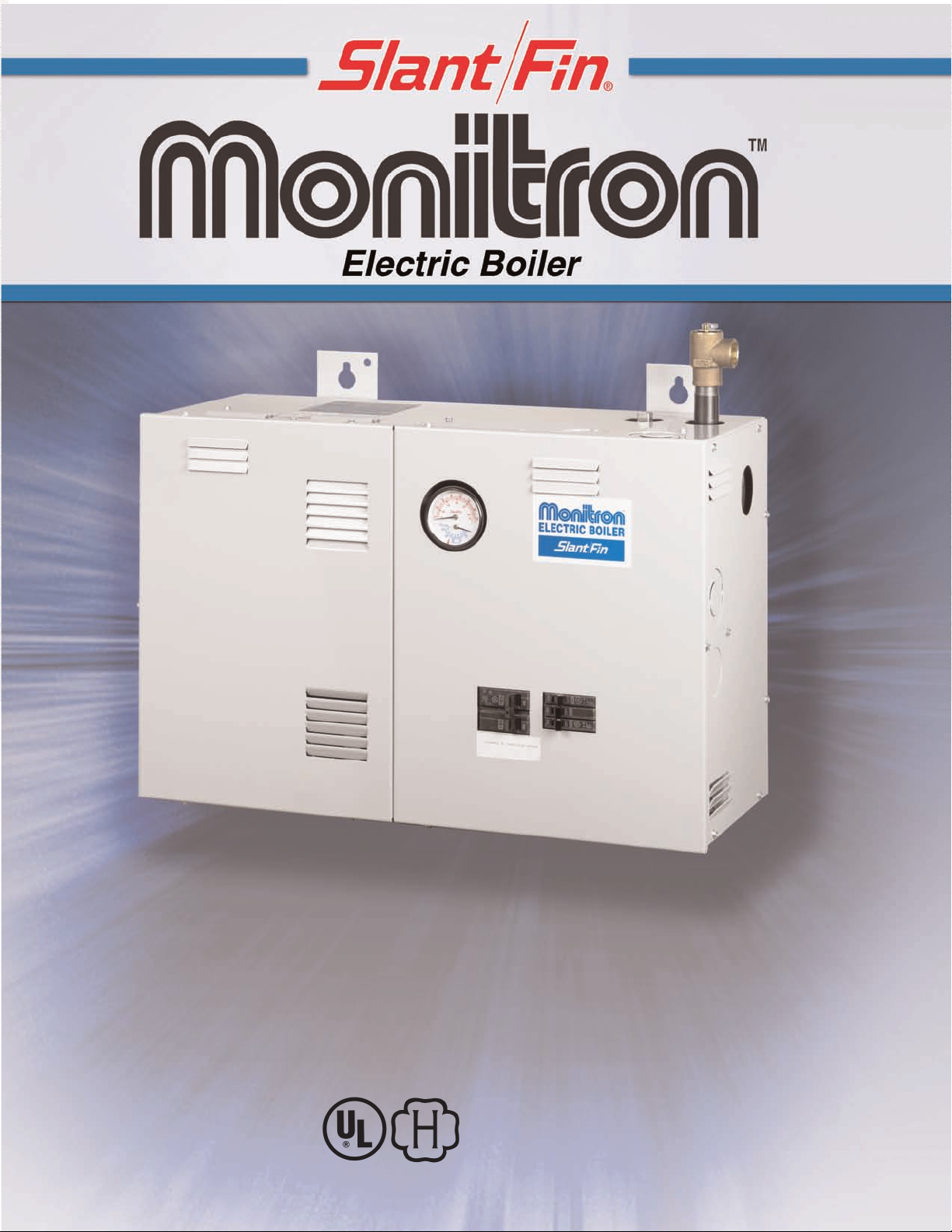
Monitron Compact, easy to install for new or “standby” installations
TM
Monitron combines the availability and dependability of electricity with the
comfort and performance of conventional hydronic heating using baseboard,
radiant or cast-iron radiators.
Monitron as a replacement unit: Works with virtually any existing
hot water hydronic radiation system. Although rated in kilowatts, it is
also clearly identified by BTU output.
Monitron as a standby unit: Particularly suitable for commercial
and industrial facilities, or office buildings which can’t risk down-time
with their existing heating equipment. If oil or gas is temporarily unavailable, the owner easily switches the heating system to the electric boiler.
Monitron as a primary heating unit offers:
• The convenience of electricity and the comfort of hydronics.
• The elimination of a chimney.
• Competitive pricing with electric baseboard systems.
• Simple zoning by zone valves.
Monitron by Slant/Fin is the electronic-age boiler designed to save
energy for new or existing heating systems.
TO ZONE VALVE
TRANSFORMER
WHEN USED
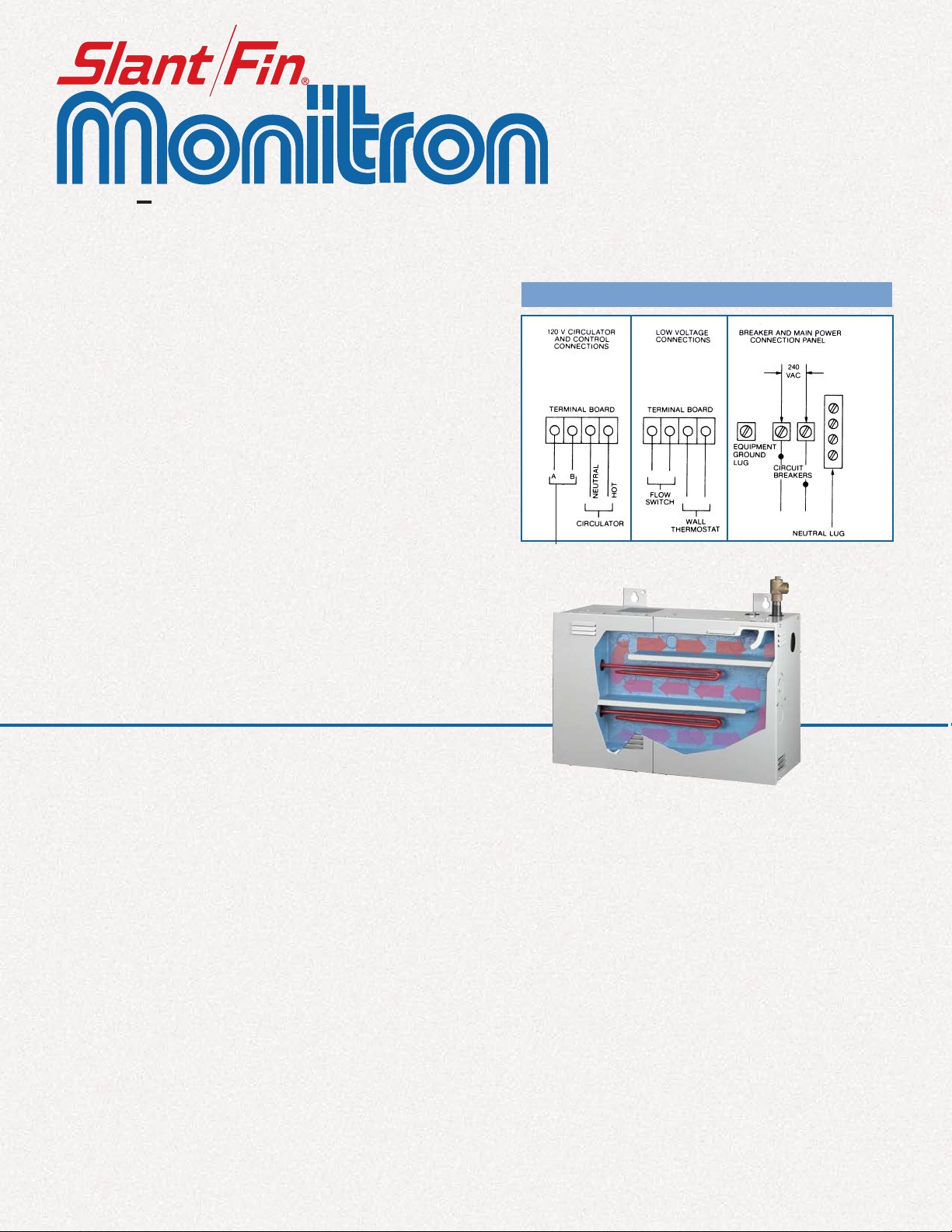
TYPICAL WIRING DIAGRAM
Monitron installed as primary boiler.
America’s Best - Built Electric Boiler
• One piece cast-iron heat exchanger.
• Built in air eliminator.
• Internal baffles improve heat transfer.
Energy-saver
electric sequential control package
With manual mild-weather energy-saver switches *
NORMAL OPERATIONS
When the thermostat calls for heat, the circulator turns on and the
first electric heater bank is energized. At preset 30-second intervals,
the other heater banks automatically energize. The circulator continues operating until the room thermostat is satisfied. A flow switch
supplied by Slant/Fin or others is required. It prevents the elements
from being energized unless the circulator is operating. This avoids
element burnout.
* All models except EH-8 and EH-10
OPTIONAL MILD-WEATHER OPERATION
Mild-weather energy savings are made possible through the use of
circuit breakers on the breaker panel.This permits the owner to
manually switch off one or more of the elements.Then, when just a
moderate amount of heat is needed, all the elements are not energized, cycling is reduced, and overheating is diminished.This energy-saving feature is standard on Monitron models EH-12-S through
EH-40-S.
Standard equipment
• Dual limit aquastat
• Altitude pressure and temperature gauge
• Safety relief valve (unmounted)
• Circulator relay and heater contactors
• Circuit breaker (one or two heaters per breaker)
• Low voltage thermostat with adjustable heat anticipator
(packed separately)
• Drain cock,
• Built-in air separator
3
⁄4 " (packed separately)
• Cast-iron ASME approved heat exchanger
• Terminal blocks for circulator, thermostat, flow switch and
• Sequencer
• Complete jacketing
• U.L. listed, ASME authorized
• Flow switch. Not included with, but necessary on all models
• Circuit breaker for circulator and control circuit.
*
for zone valve transformer
Page 3
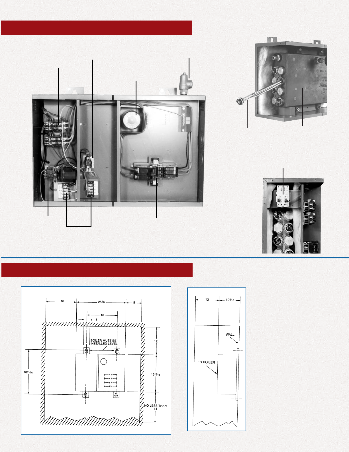
FEATURES
CONTACTORS
FOR HEATER
ELEMENTS
SEQUENCER
30 PSI PRESSURE
RELIEF VALVE
ALTITUDE
PRESSURE
AND TEMPERATURE
GAUGE
CIRCULATOR
RELAY
TERMINAL
BLOCKS
DIMENSIONS
CIRCUIT BREAKERS
HEATER
ELEMENTS
DUAL LIMIT AQUASTAT
CAST IRON
ASME HEAT
EXCHANGER
NOTES:
1. May be totally enclosed.
2. All clearance dimensions are
minimum.
3. All dimensions are in inches.
Page 4

RATINGS AND SPECIFICATIONS
SINGLE
SINGLE
PHASE
Boiler
Model No.
EH8S 8 27000 14-12 12 6-2/0 14-4 6-4 33 ––– ––– ––– ––– ––– –––
EH10S 10 34000 14-12 12 6-2/0 14-4 6-4 42 ––– ––– ––– ––– ––– –––
EH12S 12 41000 14-12 12 6-2/0 14-4 6-4 50 9.012 31000 6-2/0 14-4 6-4 25.1
EH16S 16 55000 14-12 12 6-2/0 14-4 6-4 67 12.016 41000 6-2/0 14-4 6-4 ‡38.1
EH20S 20 68000 14-12 12 6-2/0 14-4 6-4 83 15.020 51000 6-2/0 14-4 6-4 ‡48
EH24S 24 82000 14-12 12 6/2/0 14-4 6-4 100 18.024 62000 6-2/0 14-4 6-4 ‡60
EH28S 28 96000 14-12 12 2-250 MCM 14-4 6-4 117 21.028 72000 6-2/0 14-4 6-4 ‡60
EH32S 32 109000 14-12 12 2-250 MCM 14-4 6-4 133 24.032 82000 6-2/0 14-4 6-4 ‡73
EH40S 40 137000 14-12 12 2-250 MCM 6-2/0 ––– 167 30.040 103000 6-2/0 14-4 6-4 ‡95.4
* Multiply by 0.751 for values at 208 volts AC.
** Multiply by 0.867 for values at 208 volts AC.
† For total current add, to the value shown in the table, the current draw for
‡ Leg with the highest value of line current of an unbalanced 3 phase load.
* KW at
240 VAC
circulator and/or zone valve transformer (12 Amp. max.),
PHASE
D.O.E
Capacity
*(Btu/hr) at
240 VAC
Neutral Lug
Size (AWG)
Solid
Cu ¶ AL
Stranded
Cu ¶ AL
SINGLE PHASE –– THREE WIRE
Main Lug
Size (AWG)
CU ¶ AL
Grounding
Lug Size
(AWG)
Cu
¶ AL
THREE PHASE –– FOUR WIRE 208 VAC WYE §
† ** Heater
Amps at
240 VAC
¶ Aluminum conductors may be used, lug size, conduit size, ampacity and all
applicable codes permitting. However, aluminum conductors may not be
used for model EH-40 single phase.
§ 3 phase 240V special model also available.
Consult factory for information.
KW at
208 VAC
D.O.E
Capacity
(Btuh) at
208 VAC
Main Lug
Size (AWG)
CU ¶ AL
Grounding
Lug Size
(AWG)
¶ AL
Cu
† Heater
Amps at
208 VAC
Specify Model as follows: Model Number. Single or three Phase.
“135S” for single phase, 120V/240V, 120V/208V WYE. 3 wire (see
note (1) below) with control circuit breaker.
Example: EH-20-135S=20KW boiler for 120V/240V.
120V/208V Single Phase 3 wire.
“345S” for three phase, 120V/208V WYE. 4 wire (see note (1)
below) with control circuit breaker.
Note No. 1: Voltage of any line to ground cannot exceed
125 VAC.
ELECTRICAL
• Single branch circuit for 3 wire 120/208 V WYE, 120/240 Volt a.c.
single phase, 60 Hz or for 4 wire 120/208V WYE three
phase, 60Hz a.c. See note (1) above.
• Circulator relay 12 AMP Max, 120V a.c.
• Heating elements: Low-density replaceable. Copper sheathed
• Relays: Heavy-duty contactors, 48 AMP U.L. rating
TYPICAL PIPING DIAGRAM
FOR USE WITH TWO-WAY ZONE VALVES
and silver brazed base.
NOTES:
1. Optional blocking gate valve and hose end valve
used (with drain valve) for fast fill and purge of
system.
IMPORTANT Close bypass line valve
(if used) during purging.
2. Circulator should not be installed at lowest point
of piping.
3. There should be no elbows, tees, or change of
pipe size for at least 5 diameters of pipe size
(see table below) upstream and downstream of
flow switch.
Boiler Model
EH-40 FS8W 1 1⁄4 IN. 8 1⁄2 IN.
EH-8 Thru EH-32 FS4-3T3-1 1 IN. 6 1⁄2 IN.
Flow Switch
McDonnell
& Miller No.
Minimum Length of
Straight Pipe Upstream
Pipe
Size
and Down-Stream
of Flow Switch
© Slant/Fin Corp. 2003. Printed in U.S.A. 1203. Publication EH-10
SLANT/FIN CORPORATION., Greenvale, N.Y. 11548 • www.slantfin.com
Phone: (516) 484-2600 • Fax: (516) 484-5921
In Canada: Slant/Fin LTD/LTEE, Mississauga, Ontario • www.slantfin.ca
 Loading...