

Page 1

Page 2
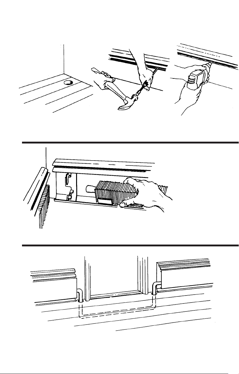
highlights of quick, easy Slant/Fin installation
1. Drill holes for risers and
connecting piping.
3. Join the elements to risers and each other and rest on brackets.
2. Nail baseboard to wall. For faster installation,
use “T-Shot” Nailing Tool, or, use power
screw gun.
4. Drop piping under doorways.
Page 3
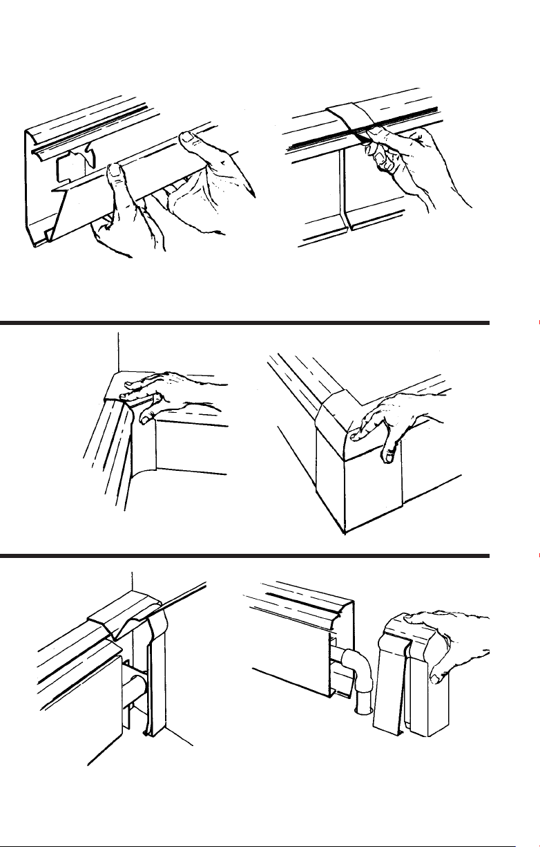
Slant/Fin installation
5. Snap front panel back in place.
7. Snap on inside corners and outside corners.
6. Join baseboard lengths
with splice plates.
8. Install wall trims at partitions.
9. Slide on end caps f
or finishing touch.
Page 4
®
easiest kind of heating
to install
(and the most beautiful)
You’ll find that pre-assembled Slant/Fin baseboard
is surprisingly easy to handle. With Slant/Fin precut lengths and telescoping accessories you can
leave your hacksaw at home. All parts snap together securely at the touch of your fingers, and they
stay together. You end up with a neat, wall-to-wall
installation of beautiful and efficient baseboard
heating, without a shortened temper or bleeding
hands. And you’re in and out in half the time you’d
need with most other baseboards.
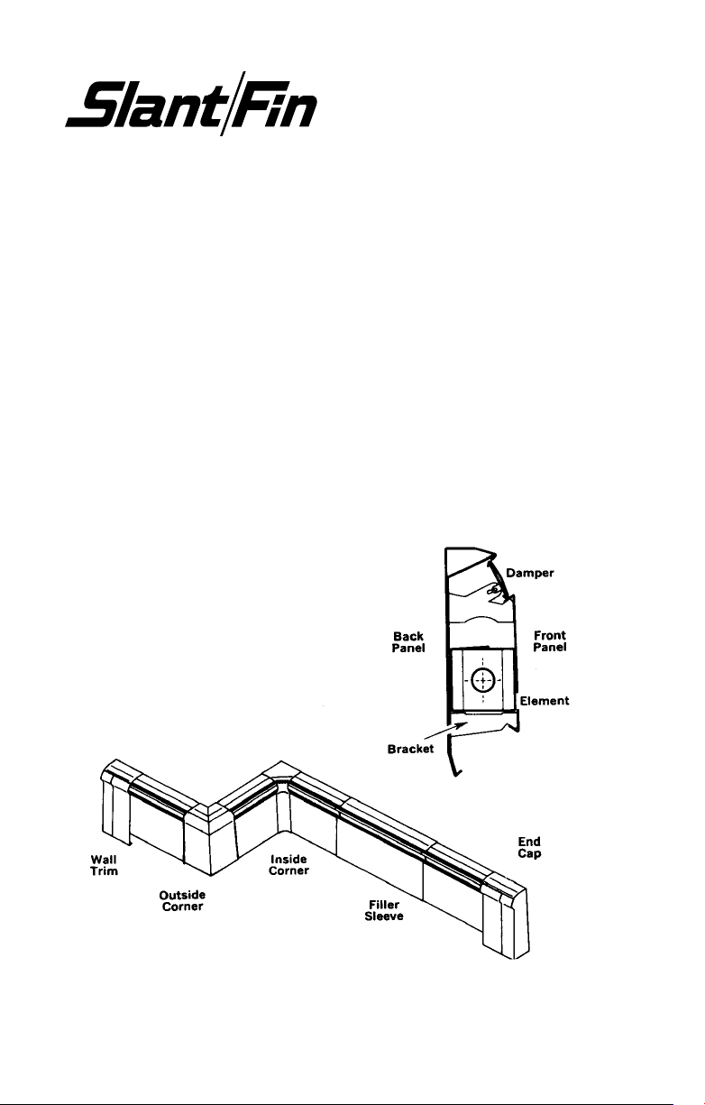
what the parts are called...
Baseboard and all accessor
recessed installation.
ies serve both flush or
Page 5
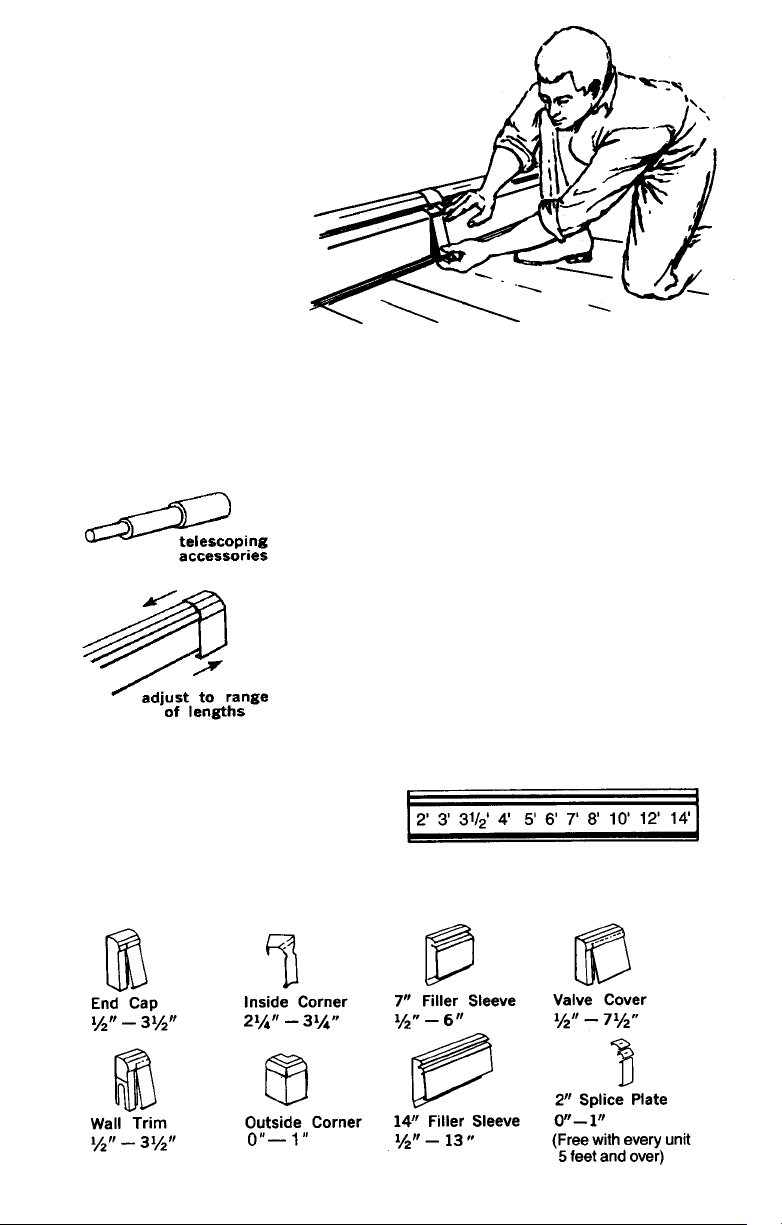
variety of stock lengths and
adjustable accessories assure
neat fit without cutting...
Slant/Fin baseboard units come in a wide variety of
standard lengths.The Slant/Fin accessories simply
snap over and behind the baseboard units permitting
them to slide left or right. The amount of overlap can
be adjusted from only 1/2” to almost the full width of
the accessory.This way you can virtually “stretch” or
compress standard lengths of baseboard and accessories to fit any length of wall without cutting them.
Slant/Fin installs faster than any other baseboard in
he world.
LENGTH NEEDED: (Simply determine which combination satisfies requirements).
These stock lengths are available in
both the complete baseboard package and enclosure only (the unit
without heating element, sometimes
referred to as dummy cover).
S/F accessories adjust telescopically to these lengths:
Page 6

plan your piping...
Here are examples of three basic piping systems, shown with and without options
for zoning.
1. SERIES LOOP
Series loop--single zone
(The simplest, most economical
system to install.) The Slant/Fin
baseboard damper provides individual room control. A single circuit runs from the boiler to the first
run of baseboard, continues from
there to the next room and so on.
The last baseboard unit in the
series is connected to the return
at the boiler. It keeps pipe, fittings,
controls and labor costs to a minimum. Use separate loop for each
zone.
Series loop--multiple zones
Each zone is a “Series loop” with
any number of Slant/Fin baseboard units and controlled by its
own room thermostat.
zone valve arrangement,
In the
each zone has an electrically
operated zone valve and there is
a single pump for the whole
system.
zone pump arrangement,
In the
each zone is provided with a
pump, a flow control valve and a
relay.
ies loop--m
Ser
individual pumps
ulti-z
one with
Page 7

2. SPLIT LOOP Provides more even
heat distribution and the option of
separate zone control. The house is
“divided” into two (or more) sections, each with its own circuit.
Each circuit draws water of the
same temperature from a central
trunk line. Balancing valves should
be installed in each circuit at return
end just before entering circulator.
3. ONE PIPE WITH DIVERTER TEES
Permits individual room shut-off or
thermostatic control. Each baseboard unit is connected to the main
by a supply and return branch connection (usually with a shut-off
valve at the diverter tee). This offers
a sophisticated system of room
temperature control, particularly in
conjunction with Slant/Fin’s fully
modulating damper.
air elimination...
Provision must be made for venting air from system, to prevent
noise or blockage of circulation by air pockets. Either install a
manual air vent at every drop, or install an automatic air eliminator
device at the boiler and a vent at highest point of the system for
extra safety. A vent at every drop is an advantage in case the system is later drained and refilled without purging.
Page 8

figure out
what material
to order...
First take wall to wall measurements
of all rooms from the plan or by actual field measurement. Next, calculate
the heat loss for each room, using
the IBR or equivalent method. Then
translate the output required into the
list of materials needed for each
room and wall.
NOTE: Often a shorter-than-wall length of radiation is called for. For instance, only
8 feet of radiation may be required on a 12 foot wall. You can drop the pipe through
the floor after 8’ (Method A) or continue the run to the far wall for an attractive wallto-wall look, using enclosure only with plain tubing inside (Method B). Although this
uses more material, it’s often the simplest way to do the job. At the far wall you can
drop the pipe through the floor or run it through the wall to the next room. Straight
through eliminates potential air problems. (See page 15 for tips on installing enclosure only.)
Solid line indicates baseboard.
Broken line indicates piping below
floor, or in “enclosure only”.
Method A: pipe drops through the
floor at end of “complete assembly”
baseboard.
Method B: bare
pipe runs to far wall
inside “enclosure
only”.
e out a schedule of the material you need, room by room, so when you get it
Mak
you can sort it out easily for quick installation. Then place your order.
Page 9

begin by drilling
riser holes...
The riser connects sub-floor supply tubing to
the baseboard. The diameter of the riser hole
and the location of the hole with respect to
the walls will vary depending on the type of
baseboard you’re using. Here is a handy
chart to follow:
1
”
⁄4
1
”
⁄4
1
”
⁄4
1
”
⁄4
1
”
⁄4
1
”
⁄2
3
”
⁄4
Back Wall
to Center
(floor holes)
3
”
1
⁄8
21
⁄64
21
1
⁄64
3
”
1
⁄8
3
”
1
⁄4
9
”
1
⁄16
9
”
1
⁄16
3
”
1
⁄4
Diameter
Model
BL-50/75
15-50
15-75
30-75
81A
83A2
84A3 1” 1
85A/86AX 1
* Hole is 1/2” larger than pipe to allow for expansion. Install riser
snug to inside edge of hole to allow maximum room for riser to
move to outside edge of hole when pipe expands.
1
⁄2
Pipe
”
1
3
3
3
3
or
1
3
”
⁄2
”
⁄4
”
⁄4
”
⁄4
”
⁄4
”
⁄4
Hole*
”
⁄4
1
1” 1
1
1
1
1
1
Floor to
Center
(partition holes)
2
”
”
3”
3”
3
3
3
3
3
5
”
⁄16
3
”
⁄16
7
”
⁄8
1
”
⁄2
1
”
⁄2
7
”
⁄8
distribute the cartons along the
walls...
To make installation easy, lay out the cartons
of material and accessories along the wall in
the order in which they will be installed. Preplanning should specify which combination of
baseboard and accessories fits best.
9
Page 10

nail it up...
The pre-assembled baseboard goes right from carton to wall with Slant/Fin’s
“T-Shot” Nailing Tool (or power screw gun).You can load the Nailing Tool with
any nail up to
slip the Nailing Tool between the damper and front panel. Hit the drive rod
with the hammer and that’s it. Add another row of nails below the front panel.
If you’re working without a “T-Shot” or screw gun, snap off the front panel by
lifting it upward so the bottom bracket bends slightly upward, then pull toward
you with thumb.
1. for plaster walls...
Locate the studs in the wall and mark location above baseboard, or
on floor. It’s best to nail the baseboard at top and bottom to each stud.
2. for concrete or cinder block walls...
Use masonry nails, or install a furring strip and nail into it.
3. for a particularly solid installation...
Slide the bracket to the stud position and drive nail through the bracket
holes and the back panel.
before you drive your nails...
Make sure you leave enough room at the ends of the baseboard or other
points where accessories will have to be installed later.
NOTE: To avoid scratching or cutting yourself, always handle baseboard with care.
5
⁄16” round head. Just place the baseboard against the wall, and
solder the elements...
1. Clean and solder the adjoining element ends together using a non-corrosive
flux, and connect elements to risers.
2. Immediately upon completion, flush system thoroughly. Left unflushed, flux
can cause pitting in copper tubing of unfilled systems.
Fill system as soon as possib
3.
4. Make sure cradles are centered over brackets to allow for smooth expansion
without scraping noises.
le but prevent from freezing.
Page 11

Provide for
expansion with
HYDRO/TITE
expansion couplings
on long straight runs.
All piping expands when heated. In shorter runs, the movement of the risers
in their holes will take care of expansion. But on longer runs, it’s wise to
install an expansion compensator to prevent strains at the joints and buckling
of the elements. Install a Hydro/Tite at the center of a long run.
FLOW DIRECTION must be as shown, to
keep sludge from clogging the seals inside
the Hydro/Tite.
PULL OPEN until red line just shows under
the knurled collar. Install in this extended
position.
DON’T LOOSEN or tighten the knurled
collar. Proper adjustment (set at factory)
is hand-tight only.
KEEP HEAT AWAY from the knurled collar
and the coupling body, to avoid damage.
Use soft solder only
.
Page 12

replace front cover...
BASELINE 2000, FINE/LINE 30 & MULTI/PAK 80
Place lower edge underneath lower bracket.
Lift slightly and press upper edge forward
with thumb till panel snaps into place.
FINE/LINE 15
Place top edge of front panel on bracket
with panel in “up” position, swing down.
Important: to lock the panel to the bracket, pull cover outward away from bracket,
while swinging down. Push bottom of
panel to engage lower bracket.
snap on the accessories...
WALL TRIMS, END CAPS, CORNERS
For a neat finish at partitions, use the wall
trim (adjustable up to 3
recommended at each drop; either wall
trim or end caps (both hinged) provide
easy access to vent. These accessories
eliminate the wasteful need for cutting
large baseboard units to fit small gaps,
and save you time and effort. Attractive
inside and outside corners assure a
custom look.
FILLER SLEEVE, SPLICE PLATES
The Filler Sleeve has 4 parts: back
piece, damper sleever, top sleeve, front
sleeve. The Splice Plate is exactly the
same, but without a back piece.
12
1
”
⁄2
). Air vents are
Page 13

FILLER SLEEVES (cont’d)
1. When mounting the baseboard to the wall,
be sure the filler sleeve will overlap each
baseboard unit by at least
2. Slip in the back piece so that the bent
edge rests in the bottom channel of the
baseboard. Nail the back piece to the wall
to hold it in place.
3. Move both dampers to half-open position.
Hold the damper sleeve with the crimped
edge away from you. Hook it’s front edge
over the front edges of the dampers. Snap
the back edge of the sleeve into place by
pinching -- with thumb pressure on the
baseboard top panel and finger pressure
up under the back edge of the damper.
3A. (For Multi/Pak 80)
Move both dampers to
half open position.
Hook the damper
sleeve’s top edge over
the top edge of the
dampers. Press down
on the sleeve and
snap the bottom edge
into place.
1
⁄2”.
4. Hook the sharp angle of the top sleeve
over the front edge of the baseboard’s top
panel. Press down on the back edge until
the sleeve snaps into place.
5. Replace baseboard front covers. Hook the
front sleeve’s top edge over the front covers and snap the bottom edge into place.
Page 14

fine points, for a perfect job
RISER-RINGS slip
around tubing where it
passes through
flooring. They provide
neat, clean, sanitary
seal and absorb
expansion squeaks
and vibration noises.
May be installed after
connections are made.
FAST/FLEX CONNECTORS can be hand-formed
to fit varied piping problems. Use them to fit around
obstructions, compensate for misalignment, soak
up vibration and expansion at turns, eliminate
many solder joints. Cannot be used as an
expansion compensator.
for problem areas...
PEX-TO-BASEBOARD
CONNECTOR
PEX tubing is used to
and from the boiler,
Slant/Fin Terra Therma
PEX adapters connect
tubing to copper baseboard heating element.
When
HYDRONIC FLOOR BOX HEATER
recesses neatly into the floor for
upted heating comf
uninterr
doors and floor length windows. Ask for
publication HFB-10
t at patio
or
THE KICKER multi-purpose fan
convection heater fits in kickspace
under kitchen cabinets or bathroom
vanities. Ask for publication TK-10
Page 15

fine points using enclosure only...
Use Slant/Fin hanger to
support the bare tubing at
the same height as adjoining heating elements. Insert the short hook of the
hanger as shown. Install
from the left side, so that
the large hook (which
holds the tubing) faces the
rear panel.
when a normal loop
can’t be run...
In some installations, it’s not possible to drop the return line below the floor. In
this case, run the return tubing within the baseboard enclosure. Support with
wire hanger which you can shorten to hold the tubing in the space between the
heating element and bracket arm. For Base/Line 2000, a special cutout in the
bracket arm accommodates return tubing. Use a Slant/Fin return bend to connect the heating element with the return line above it. This fitting has a conven-
1
”
⁄8
ient
IPS threaded opening to receive an air vent.
replacing old
standing radiators...
A handy illustrated guide from Slant/Fin helps
you figure how many feet of baseboard it takes to
equal the heat output of most styles of standing
cast-iron r
adiators
or publication RC-40.
Ask f
.
Note: If the baseboard is
installed below the boiler
level, as in many slab
jobs, the return bend may
be installed with the vent
opening pointed downward, and plugged. This
permits easy drainage if
needed.
15
Page 16

...wasn’t that easy?
®
©Slant/Fin Corp. 1994. Printed in USA 103. Publication No. BB-40
Amer
baseboard con
ale, N.Y. 11548 • Phone: (516) 484-2600
v
Green
SLANT/FIN CORPORA
TION,
ica’
www.slantfin.com
. 1 brand of
s No
ection heating
v
 Loading...