

Skil 1827,1817,1830 Operating Instructions Manual

Read BeforeUsing Lireavant usage Leer antesdeusar
Operating/SafetyInstructions
Consignesdefonctionnement/s6curit6
Instruccionesdefuncionamientoy seguridad
1817
1827
1830
CallToll Freefor
ConsumerInformation
&ServiceLocations
Pour obtenirdesinformations
et les adressesdenoscentres
deserviceapr_s-vente,
appelezce numdrogratuit
Llame gratispara
obtenerinformaciOn
para el consumidory
ubicacionesde servicio
ForEnglishVersion Versionfran_;aise Versi6nen espafiol
See page 2 Voirpage19 Vet la pdgina36

Read all safety warnings and all instructions. Failure to follow the
warnings and instructions may result in electric shock, fire and/or serious injury.
SAVE ALL WARNINGS AND INSTRUCTIONS FOR FUTURE REFERENCE
The term "power tool" in the warnings refers to your mains-operated (corded) power tool or
battery-operated (cordless) power tool.
Work area safety
Keep work area clean and well lit. Cluttered
or dark areas invite accidents.
Do not operate power tools in explosive
atmospheres, such as in the presence of
flammable liquids, gases or dust. Power
tools create sparks which may ignite the dust
or fumes.
Keep children and bystanders away while
operating a power tool. Distractions can
cause you to lose control.
Electrical safety
Power tool plugs must match the outlet,
Never modify the plug in any way, Do not
use any adapter plugs with earthed
(grounded) power tools. Unmodified plugs
and matching outlets will reduce risk of electric
shock.
Avoid body contact with earthed or grounded
surfaces such as pipes, radiators, ranges
and refrigerators. There is an increased risk
of electric shock if your body is earthed or
grounded.
Do not expose power tools to rain or wet
conditions. Water entering a power tool will
increase the riskof electric shock.
Do not abuse the cord. Never use the cord
for carrying, pulling or unplugging the power
tool. Keep cord away from heat, oil, sharp
edges or moving parts. Damagedor entangled
cords increase the risk of electric shock.
When operating a power tool outdoors,
use an extension cord suitable for outdoor
use. Use of a cord suitable for outdoor use
reduces the risk of electric shock.
If operating the power tool in damp locations
is unavoidable, use a Ground Fault Circuit
Interrupter (GFCl) protected supply. Use of
an GFCI reduces the riskof electric shock.
Personal safety
Stay alert, watch what you are doing and
use common sense when operating a
power tool, Do not use a power tool while
you are tired or under the influence of drugs,
alcohol or medication.A moment of inattention
while operating power tools may result in
serious personal injury.
Use personal protective equipment. Always
wear eye protection. Protective equipment
such as dust mask,non-skid safety shoes, hard
hat, or hearing protection used for appropriate
conditions will reduce personal injuries.
Prevent unintentional starting. Ensure the
switch is in the off-position before
connecting to power source and / or battery
pack, picking up or carrying the tool.
Carrying power tools with your finger on the
switch or energizing power tools that have the
switch on invitesaccidents.
Remove any adjusting key or wrench before
turning the power tool on. A wrench or a
key left attached to a rotating part of the
power tool may result in personal injury.
Do not overreach. Keep proper footing and
balance at all times. This enables better
control of the power tool in unexpected
situations.
Dress properly. Do not wear loose clothing
or jewelry. Keep your hair, clothing and
gloves away from moving parts. Loose
clothes, jewelry or long hair can be caught in
moving parts.
If devices are provided for the connection
of dust extraction and collection facilities,
ensure these are connected and properly
used. Use of dust collection can reduce dust-
related hazards.
Power tool use and care
Do not force the power tool, Use the
correct power tool for your application. The
correct power tool will do the job better and
safer at the rate for which it was designed.
Do not use the power tool if the switch does
not turn it on and off. Any power tool that
cannot be controlled with the switch is
dangerous and must be repaired.
-2-
Disconnect the plug from the power source
and/or the battery pack from the power tool
before making any adjustments, changing
accessories, or storing power tools. Such
preventive safety measures reduce the risk of
starting the power tool accidentally.
Store idle power tools out of the reach of
children and do not allow persons unfamiliar
with the power tool or these instructions to
operate the power tool. Power tools are
dangerous in the hands of untrained users.
Maintainpowertools. Checkfor misalignment
or binding of moving parts, breakage of
parts and any other condition that may
affect the power tool's operation. If damaged,
have the power tool repaired before use.
Many accidents are caused by poorly
maintained power tools.
Keep cutting tools sharp and clean. Properly
maintained cutting tools with sharp cutting
edges are less likely to bind and are easier to
control.
Use the power tool, accessories and tool
bitsetc. in accordancewiththese instructions,
taking into account the working conditions
and the work to be performed. Use of the
power tool for operations different from those
intended could result in a hazardous situation.
Service
Have your powertool serviced by a qualified
repair person using only identical
replacement parts. This will ensure that the
safety of the power tool is maintained.
Safety Rules for Routers
Hold power tool by insulated gripping
surfaces when performing an operation
where the cutting tool may contact hidden
wiring or its own cord. Contact with a "live"
wire will make exposed metal parts of the
tool "live" and shock the operator.
Use clamps or another practical way to
secure and support the workpiece to a
stable platform. Holding the work by hand or
against your body leaves it unstable and may
lead to lossof control.
Always make sure the work surface is
free from nails and other foreign objects.
Cutting into a nail can cause the bit and the
tool to jump and damage the bit.
Never hold the workpiece in one hand and
the tool in the other hand when in use.
Never place hands near or below cutting
surface. Clamping the material and guiding
the tool with both hands is safer.
Never lay workpiece on top of hard
surfaces, like concrete, stone, etc...
Protruding cutting bit may cause tool to jump.
Always wear safety goggles and dust
mask. Use only in well ventilated area.
Using personal safety devices and working in
safe environment reduces risk of injury.
After changing the bits or making any
adjustments, make sure the collet nut and
any other adjustment devices are
securely tightened. Loose adjustment
device can unexpectedly shift, causing loss
of control, loose rotating components will be
violently thrown.
Never start the tool when the bit is
engaged in the material. The bit cutting
edge may grab the material causing loss of
control of the cutter.
Always hold the tool with two hands
during start-up. The reaction torque of the
motor can cause the tool to twist.
The direction of feeding the bit into the
material is very important and it relates to
the direction of bit rotation. When viewing
the tool from the top, the bit rotates
clockwise. Feed direction of cutting must
be counter-clockwise. NOTE: inside and
outside cuts will require different feed
direction, refer to section on feeding the
router. Feeding the tool in the wrong
direction, causes the cutting edge of the bit
to climb out of the work and pull the tool in
the direction of this feed.
Never use dull or damaged bits. Sharp
bits must be handled with care. Damaged
-3-
bits can snap during use. Dull bits require
more force to push the tool, possibly causing
the bit to break.
Never touch the bit during or immediately
after the use. After use the bit is too hot to
be touched by bare hands.
Never lay the tool down until the motor
has come to a complete standstill. The
spinning bit can grab the surface and pull the
tool out of your control.
Never use bits that have a cutting
diameter greater than the opening in the
base.
GFCI and personal protection devices like
electrician's rubber gloves and footwear will
further enhance your personal safety.
Do not use AC only rated tools with a DC
power supply. While the tool may appear to
work, the electrical components of the AC
rated tool are likely to fail and create a hazard
to theoperator.
Keep handles dry, clean and free from oil
and grease. Slippery hands cannot safely
control the power tool.
Develop a periodic maintenance schedule
for your tool. When cleaning a tool be
careful not to disassemble any portion of
the tool since internal wires may be
misplaced or pinched or safety guard return
springs may be improperly mounted.
Certain cleaning agents such as gasoline,
carbon tetrachloride, ammonia, etc. may
damage plastic parts.
Risk of injury to user. The power cord must only
be serviced by a Skil Factory Service Center or
Authorized Skil Service Station.
I__1 Some dust created by power
sanding, sawing, grinding,
drilling, and other construction activities
contains chemicals known to cause cancer,
birth defects or other reproductive harm.
Some examples of these chemicals are:
• Lead from lead-based paints,
• Crystalline silica from bricks and cement and
other masonry products, and
• Arsenic and chromium from chemically-
treated lumber.
Your risk from these exposures varies,
depending on how often you do this type of
work. To reduce your exposure to these
chemicals: work in a well ventilated area, and
work with approved safety equipment, such as
those dust masks that are specially designed
to filter out microscopic particles.
-4-

._vmhoIs
IMPORTANT: Some of the following symbols may be used on your tool. Please study them
and learn their meaning. Proper interpretation of these symbols will allow you to operate the
tool better and safer.
Symbol Name Designation/Explanation
V Volts Voltage (potential)
A Amperes Current
Hz Hertz Frequency (cycles per second)
W Watt Power
kg Kilograms Weight
min Minutes Time
s Seconds Time
O Diameter Size of drill bits, grinding wheels, etc.
no No load speed Rotational speed, at no load
n Rated speed Maximum attainable speed
.../min Revolutions or reciprocation Revolutions, strokes, surface speed,
per minute orbits etc. per minute
0 Off position Zero speed, zero torque...
1,2, 3.... Selector settings Speed, torque or position settings.
I, II, III, Higher number means greater speed
0_8 Infinitely variable selector with off Speed is increasing from 0 setting
Arrow Action in the direction of arrow
Alternating current Type or a characteristic of current
--_ Direct current Type or a characteristic of current
Alternating or direct current Type or a characteristic of current
[] Class II construction Designates Double Insulated
Construction tools.
_) Earthing terminal Grounding terminal
Warning symbol Alerts user to warning messages
Q Li-ion RBRC seal Designates Li-ion battery recycling
program
Ni-Cad RBRC seal Designates Ni-Cad battery recycling
program
Read manual symbol Alerts user to read manual
Wear eye protection symbol Alerts user to wear eye protection
"5-

IMPORTANT: Some of the following symbols may be used on your tool. Please study them
and learn their meaning. Proper interpretation of these symbols will allow you to operate the
tool better and safer.
This symbol designates that this tool is listed by Underwriters Laboratories.
®
This symbol designates that this tool is recognized by Underwriters Laboratories.
This symbol designates that this tool is listed by Underwriters Laboratories,
to United States and Canadian Standards.
This symbol designates that this tool is listed by the Canadian Standards
Association.
C_U This symbol designates that this tool is listed by the Canadian Standards
Association, to United States and Canadian Standards.
S
This symbol designates that this tool is listed by the Intertek Testing
Services, to United States and Canadian Standards.
'_ This symbol designates that this tool complies to NOM Mexican Standards.
Conformsto
UL Standard 60745-1
UL Standard 60745-2-17
Certified to
CAN/CSAStandard C22.2 No. 60745-1
CAN/CSAStandard C22.2 No. 60745-2-17
-6-
_ isconnect the plug from the power source before making any
assembly, adjustments or changing accessories. Such preventive safety
measures reduce the risk of starting the tool accidentally.
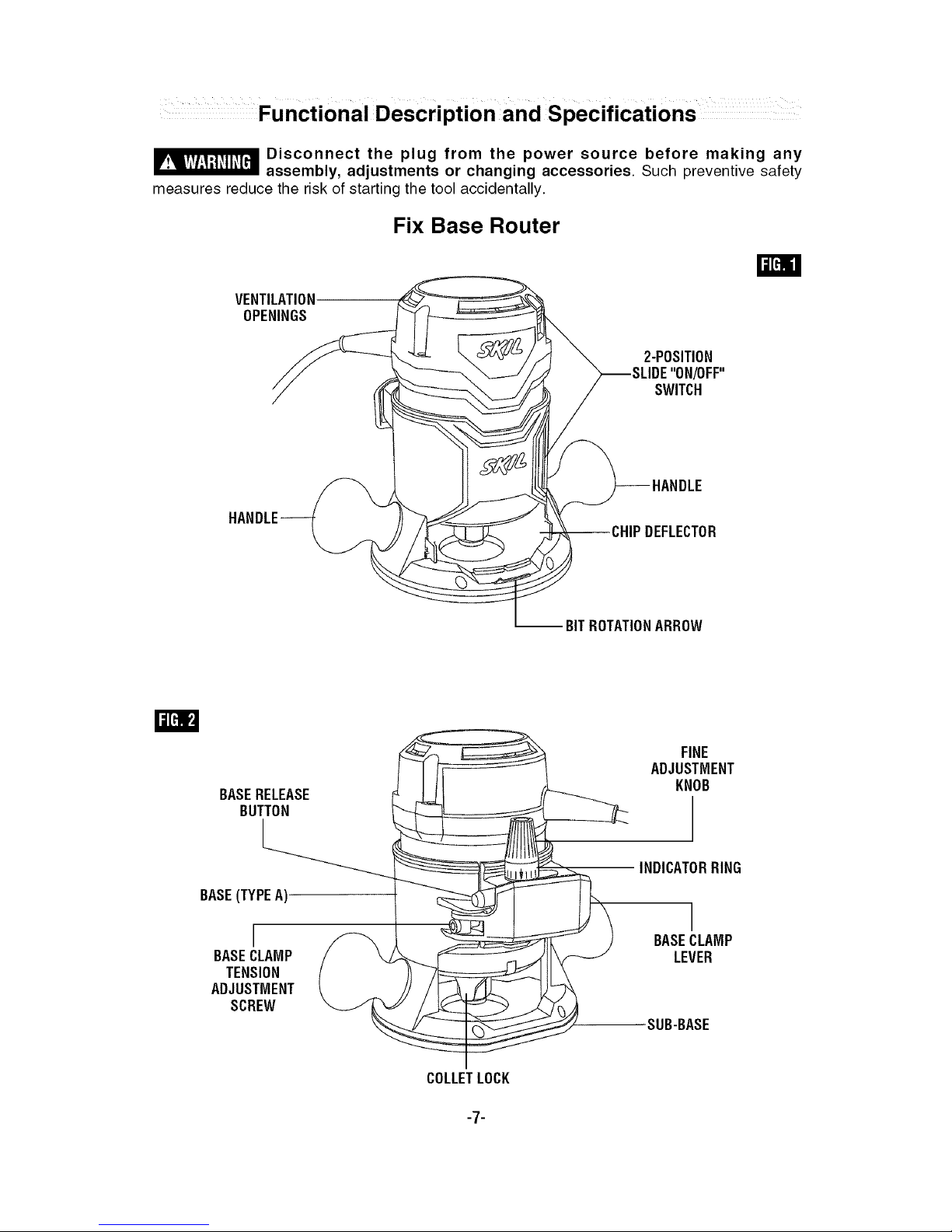
Fix Base Router
VENTILATION
OPENINGS
m
-- BITROTATIONARROW
m
BASERELEASE
BUTTON
BASE(TYPEA)
I
BASECLAMP
TENSION
ADJUSTMENT
SCREW
FINE
ADJUSTMENT
KNOB
-- INDICATORRING
BASECLAMP
LEVER
SUB-BASE
COLLETLOCK
-7-

Plunge Base Router
FINE
ADJUSTMENT_
KNOB /
VARIABLE SPEEDDIAL
(Model 1827 & 1830 only)
Jl=l[_l[_]
INDICATOR
2-POSITION
I/OFF"
SWITCH
HANDLE
DEPTHROD
DEPTHSTOP
DEFLECTOR
BITROTATIONARROW
OPENINGS
I_i[_l
LOCK
LEVER
(TYPEB)
BASECLAMP
LEVER
COLLET
Model number 1817 1827 1830
Voltage rating 120V ,_ 60Hz 120V ,_ 60Hz 120V "-_ 60Hz
Amperage rating 9.5A 10A 10A
No load speed no25,000/min no 10,500-25,000/min n o 10,500-25,000/min
Collet capacities 1/4", 1/2" 1/4", 1/2" 1/4", 1/2"
On models 1817, 1827 & 1830 router motor unit must be used with either
fixed base type A, or plunge base Type B.
"8-
Assembly
A wide assortment of router bits with different
profiles is available separately.
I__ To prevent personal injury,
always remove the plug
from power source before removing or
installing bits or accessories.
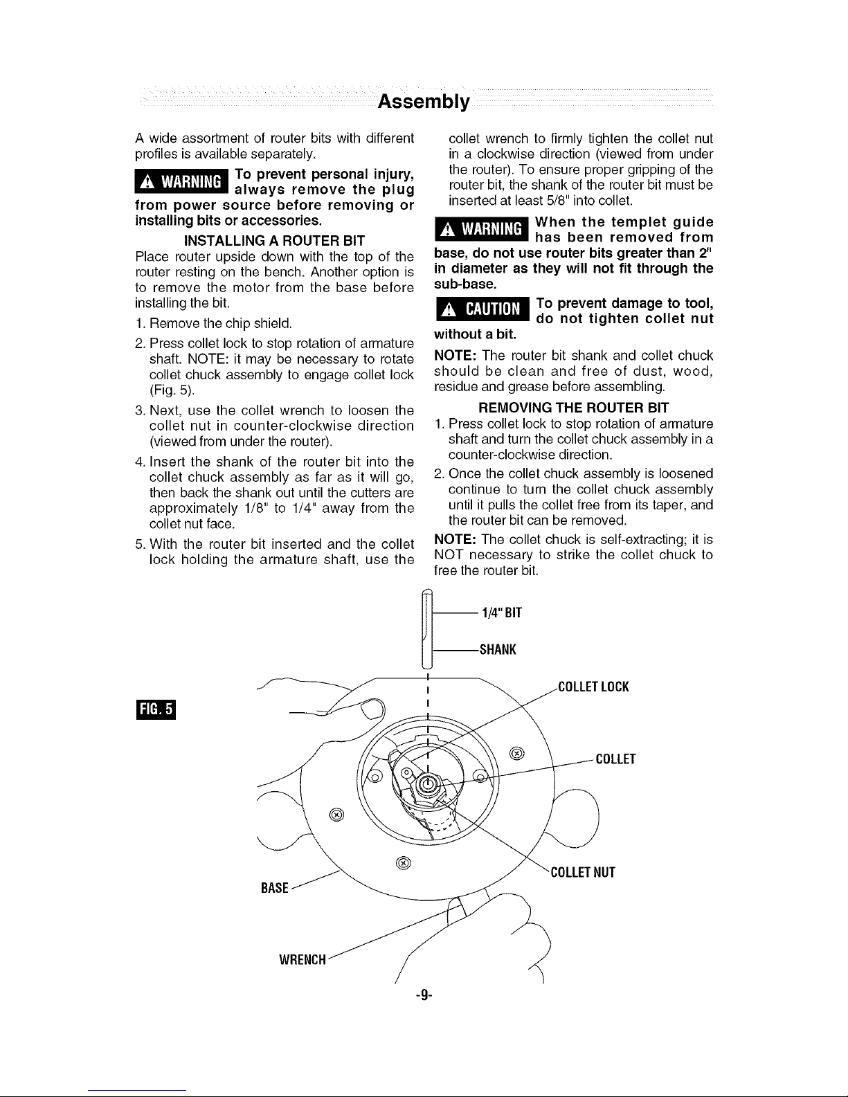
INSTALLING A ROUTER BIT
Place router upside down with the top of the
router resting on the bench. Another option is
to remove the motor from the base before
installing the bit.
1. Remove the chip shield.
2. Press collet lock to stop rotation of armature
shaft. NOTE: it may be necessary to rotate
collet chuck assembly to engage collet lock
(Fig. 5).
3. Next, use the collet wrench to loosen the
collet nut in counter-clockwise direction
(viewed from under the router).
4. Insert the shank of the router bit into the
collet chuck assembly as far as it will go,
then back the shank out until the cutters are
approximately 1/8" to 1/4" away from the
collet nut face.
5. With the router bit inserted and the collet
lock holding the armature shaft, use the
collet wrench to firmly tighten the collet nut
in a clockwise direction (viewed from under
the router). To ensure proper gripping of the
router bit, the shank of the router bit must be
inserted at least 5/8" into collet.
When the templet guide
has been removed from
base, do not use router bits greater than 2"
in diameter as they will not fit through the
sub-base.
To prevent damage to tool,
do not tighten collet nut
without a bit.
NOTE: The router bit shank and collet chuck
should be clean and free of dust, wood,
residue and grease before assembling.
REMOVING THE ROUTER BIT
1. Press collet lock to stop rotation of armature
shaft and turn the collet chuck assembly in a
counter-clockwise direction.
2. Once the collet chuck assembly is loosened
continue to turn the collet chuck assembly
until it pulls the collet free from its taper, and
the router bit can be removed.
NOTE: The collet chuck is self-extracting; it is
NOT necessary to strike the collet chuck to
free the router bit.
.1/4" BIT
SHANK
I_l[dll!,1
BASE
WRENCH
-g-
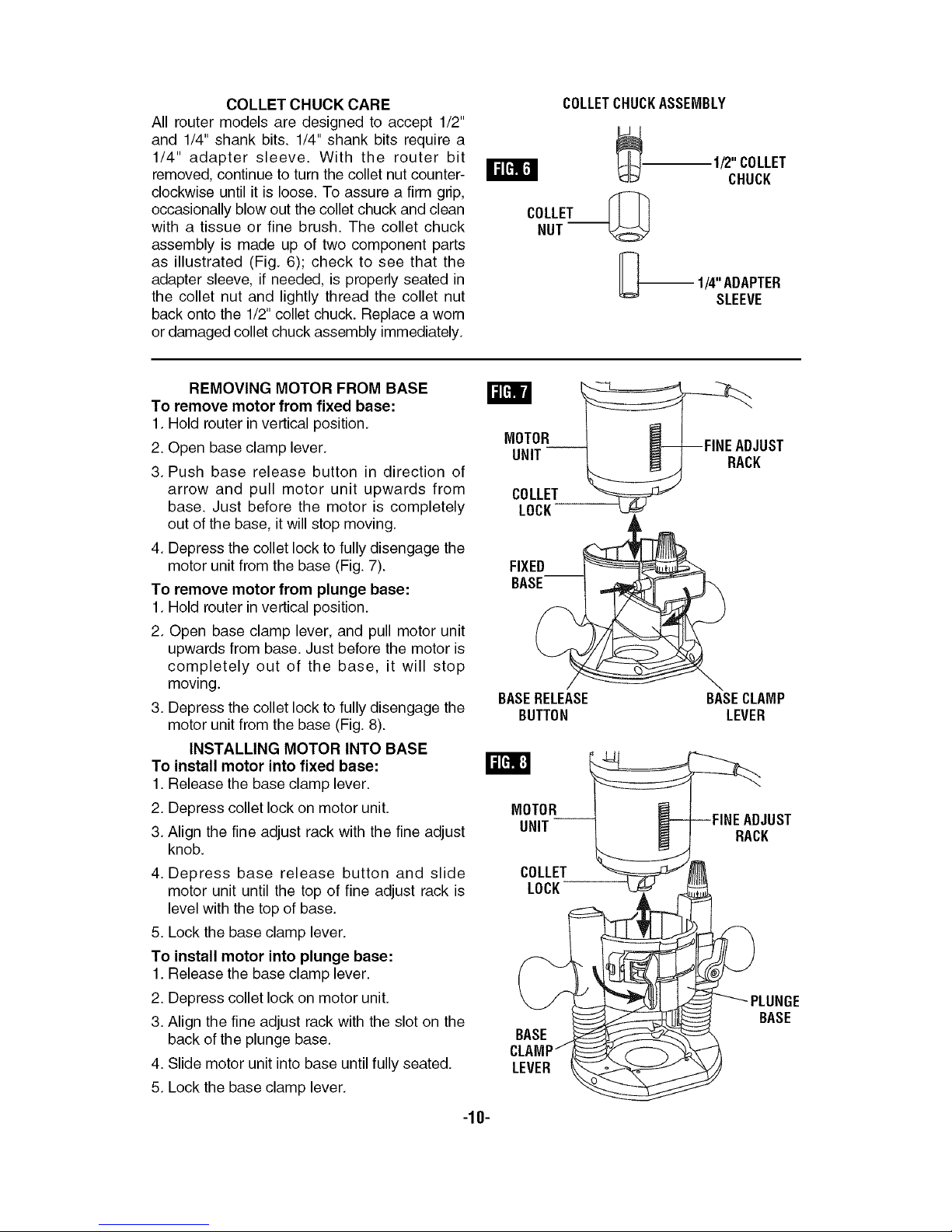
COLLET CHUCK CARE
All router models are designed to accept 1/2"
and 1/4" shank bits. 1/4" shank bits require a
1/4" adapter sleeve. With the router bit
removed, continue to turn the collet nutcounter-
clockwise until it is loose. To assure a firm grip,
occasionally blowout the collet chuck and clean
with a tissue or fine brush. The collet chuck
assembly is made up of two component parts
as illustrated (Fig. 6); check to see that the
adapter sleeve, if needed, is properly seated in
the collet nut and lightly thread the collet nut
back onto the 1/2"collet chuck. Replace a worn
or damaged colletchuck assembly immediately.
COLLETCHUCKASSEMBLY
COLLET
NUT
1/2" COLLET
CHUCK
-©
I1_1[_It'l
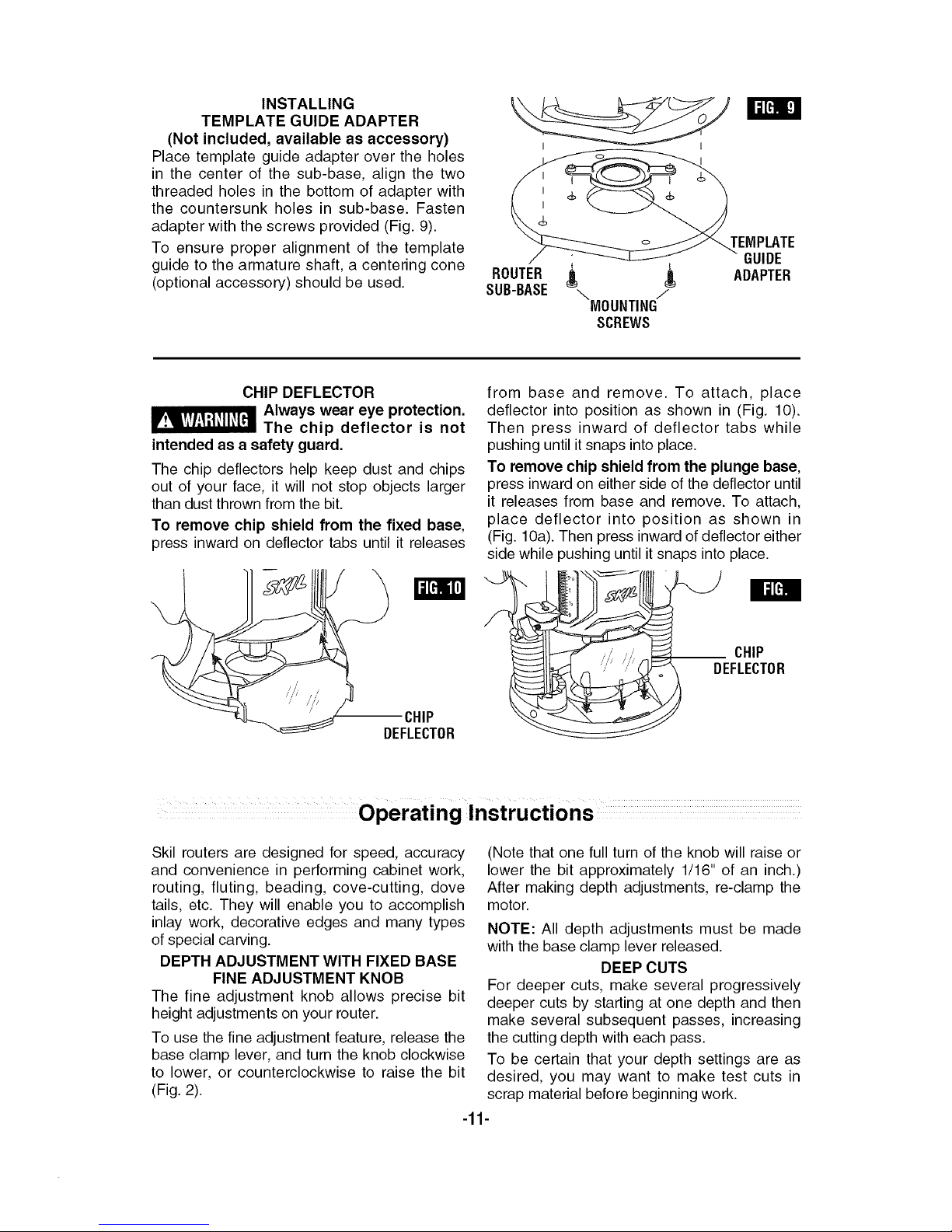
REMOVING MOTOR FROM BASE
To remove motor from fixed base:
1. Hold router in vertical position.
2. Open base clamp lever.
3. Push base release button in direction of
arrow and pull motor unit upwards from
base. Just before the motor is completely
out of the base, it will stop moving.
4. Depress the collet lock to fully disengage the
motor unit from the base (Fig. 7).
To remove motor from plunge base:
1. Hold router in vertical position.
2. Open base clamp lever, and pull motor unit
upwards from base. Just before the motor is
completely out of the base, it will stop
moving.
3. Depress the collet lock to fully disengage the
motor unit from the base (Fig. 8).
INSTALLING MOTOR INTO BASE
To install motor into fixed base:
1. Release the base clamp lever.
2. Depress collet lock on motor unit.
3. Align the fine adjust rack with the fine adjust
knob.
4. Depress base release button and slide
motor unit until the top of fine adjust rack is
level with the top of base.
5. Lock the base clamp lever.
To install motor into plunge base:
1. Release the base clamp lever.
2. Depress collet lock on motor unit.
3. Align the fine adjust rack with the slot on the
back of the plunge base.
4. Slide motor unit into base until fully seated.
5. Lock the base clamp lever.
-10-
MOTOR
UNIT
COLLET
LOCK
FIXED
BASE
BASERELEASE
BUTTON
m
MOTOR
UNIT
COLLET
LOCK
BASE
LEVER
RACK
BASECLAMP
LEVER
]E
BASE
INSTALLING
TEMPLATEGUIDEADAPTER
(Notincluded,availableasaccessory)
Place template guide adapter over the holes
in the center of the sub-base, align the two
threaded holes in the bottom of adapter with
the countersunk holes in sub-base. Fasten
adapter with the screws provided (Fig. 9).
To ensure proper alignment of the template
guide to the armature shaft, a centering cone
(optional accessory) should be used.
ROUTER _
SUB-BASE _ /
MOUNTING
SCREWS
TEMPLATE
GUIDE
ADAPTER
CHIP DEFLECTOR
_ Always wear eye protection,
The chip deflector is not
intended as a safety guard,
The chip deflectors help keep dust and chips
out of your face, it will not stop objects larger
than dustthrown from the bit.
To remove chip shield from the fixed base,
press inward on deflector tabs until it releases
)a[_li[I]
\
DEFLECTOR
from base and remove. To attach, place
deflector into position as shown in (Fig. 10).
Then press inward of deflector tabs while
pushing until itsnaps into place.
To remove chip shield from the plunge base,
press inward on either side of the deflector until
it releases from base and remove. To attach,
place deflector into position as shown in
(Fig. 10a). Then press inward of deflector either
side while pushing until it snaps into place.
_ CHIP
DEFLECTOR
Skil routers are designed for speed, accuracy
and convenience in performing cabinet work,
routing, fluting, beading, cove-cutting, clove
tails, etc. They will enable you to accomplish
inlay work, decorative edges and many types
of special cawing.
DEPTH ADJUSTMENT WITH FIXED BASE
FINE ADJUSTMENT KNOB
The fine adjustment knob allows precise bit
height adjustments on your router.
To use the fine adjustment feature, release the
base clamp lever, and turn the knob clockwise
to lower, or counterclockwise to raise the bit
(Fig. 2).
(Note that one full turn of the knob will raise or
lower the bit approximately 1/16" of an inch.)
After making depth adjustments, re-clamp the
motor.
NOTE: All depth adjustments must be made
with the base clamp lever released.
DEEP CUTS
For deeper cuts, make several progressively
deeper cuts by starting at one depth and then
make several subsequent passes, increasing
the cutting depth with each pass.
To be certain that your depth settings are as
desired, you may want to make test cuts in
scrap material before beginning work.
-11-
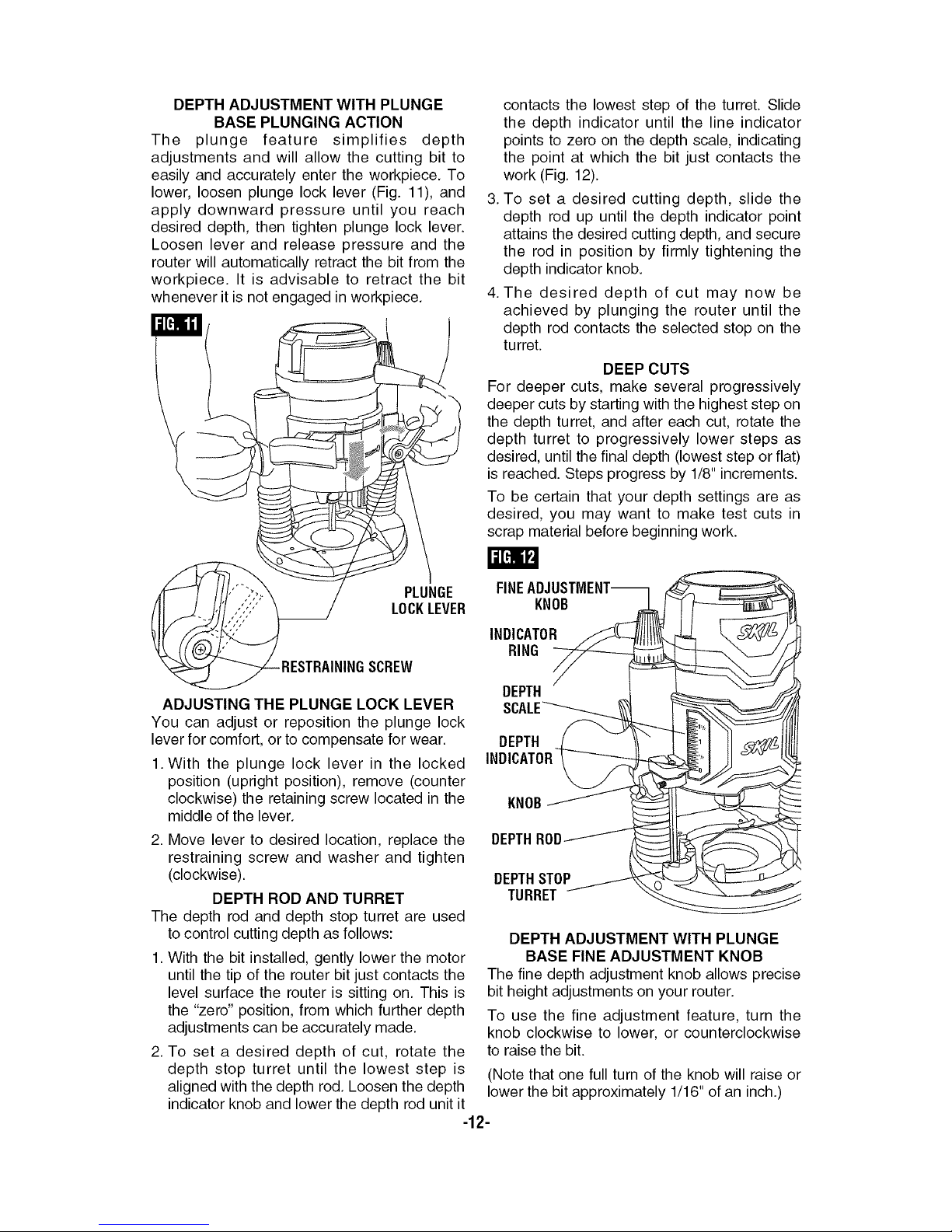
DEPTH ADJUSTMENT WITH PLUNGE
BASE PLUNGING ACTION
The plunge feature simplifies depth
adjustments and will allow the cutting bit to
easily and accurately enter the workpiece. To
lower, loosen plunge lock lever (Fig. 11), and
apply downward pressure until you reach
desired depth, then tighten plunge lock lever.
Loosen lever and release pressure and the
router will automatically retract the bit from the
workpiece. It is advisable to retract the bit
whenever it is not engaged in workpiece.
1118ii',l
PLUNGE
LOCKLEVER
SCREW
ADJUSTING THE PLUNGE LOCK LEVER
You can adjust or reposition the plunge lock
lever for comfort, or to compensate for wear.
1. With the plunge lock lever in the locked
position (upright position), remove (counter
clockwise) the retaining screw located in the
middle of the lever.
2. Move lever to desired location, replace the
restraining screw and washer and tighten
(clockwise).
DEPTH ROD AND TURRET
The depth rod and depth stop turret are used
to control cutting depth as follows:
1. With the bit installed, gently lower the motor
until the tip of the router bit just contacts the
level surface the router is sitting on. This is
the "zero" position, from which further depth
adjustments can be accurately made.
2. To set a desired depth of cut, rotate the
depth stop turret until the lowest step is
aligned with the depth rod. Loosen the depth
indicator knob and lower the depth rod unit it
contacts the lowest step of the turret. Slide
the depth indicator until the line indicator
points to zero on the depth scale, indicating
the point at which the bit just contacts the
work (Fig. 12).
3. To set a desired cutting depth, slide the
depth rod up until the depth indicator point
attains the desired cutting depth, and secure
the rod in position by firmly tightening the
depth indicator knob.
4. The desired depth of cut may now be
achieved by plunging the router until the
depth rod contacts the selected stop on the
turret.
DEEP CUTS
For deeper cuts, make several progressively
deeper cuts by starting with the highest step on
the depth turret, and after each cut, rotate the
depth turret to progressively lower steps as
desired, until the final depth (lowest step or flat)
is reached. Steps progress by 1/8" increments.
To be certain that your depth settings are as
desired, you may want to make test cuts in
scrap material before beginning work.
FINE
KNOB
INDICATOR
RING
DEPTH
DEPTH
KNOB
DEPTHSTOP
TURRET
DEPTH ADJUSTMENT WITH PLUNGE
BASE FINE ADJUSTMENT KNOB
The fine depth adjustment knob allows precise
bit height adjustments on your router.
To use the fine adjustment feature, turn the
knob clockwise to lower, or counterclockwise
to raise the bit.
(Note that one full turn of the knob will raise or
lower the bit approximately 1/16" of an inch.)
-12-
2-POSITION SLIDE "ON/OFF" SWITCH
The tool can be switched "ON" by the 2-
position slide switch located on the upper and
lower right side of the motor (Fig. 1).
TO TURN THE TOOL "ON", slide either the
upper or lower switch UP to the I position.
TO TURN THE TOOL "OFF", slide either the
upper or lower switch downward to the O
position.
Always hold the router off the work when
turning the switch on or off. Contact the work
with the router only after the router has
reached desired speed, and remove it from the
work before turning the switch off. Operating in
this manner will prolong switch and motor life
and will greatly increase the quality of your
work.
Always hold the tool with both hands while
starting the tool, since torque from the motor
can cause the tool to twist.
SOFT START FEATURE
(Included on all models)
Electronic feedback control minimizes torque
twist customary in larger routers by limiting the
speed at which motor starts.
ELECTRONIC VARIABLE
SPEED CONTROL
(Models 1827 & 1830 only)
The electronic speed control feature allows
motor speed to be matched to cutter size and
material hardness for improved finish,
extended bit life, and higher performance.
Speed changes are achieved by rotating the
dial on or between any one of the six numbers
(Fig. 3). Speed may be changed while tool is
on. The reference numbers on the dial facilitate
re-setting control to desired speed.
The speed chart indicates the relationship
between settings and application, exact
settings are determined by operator experience
and preference. The bit manufacturer may also
have a speed recommendation.
DIAL
SETTING RPM APPLICATION
1
2
3
10,500 / Nonferrous metals,
13,500 j- larger diameter bits,
16,500 and cutters
4
5
6
20,000 -_ Softwoods, plastics,
I, counter tops, smaller
22,500
J diameter bits, and
25,000 cutters
SITE-LIGHT TM
Your tool is also equipped with a Site-Light TM
for better visibility during operation.
When the tool is plugged in, the lights will turn
on automatically.
The Site-Light TM is maintenance free and was
designed to last the life of your tool.
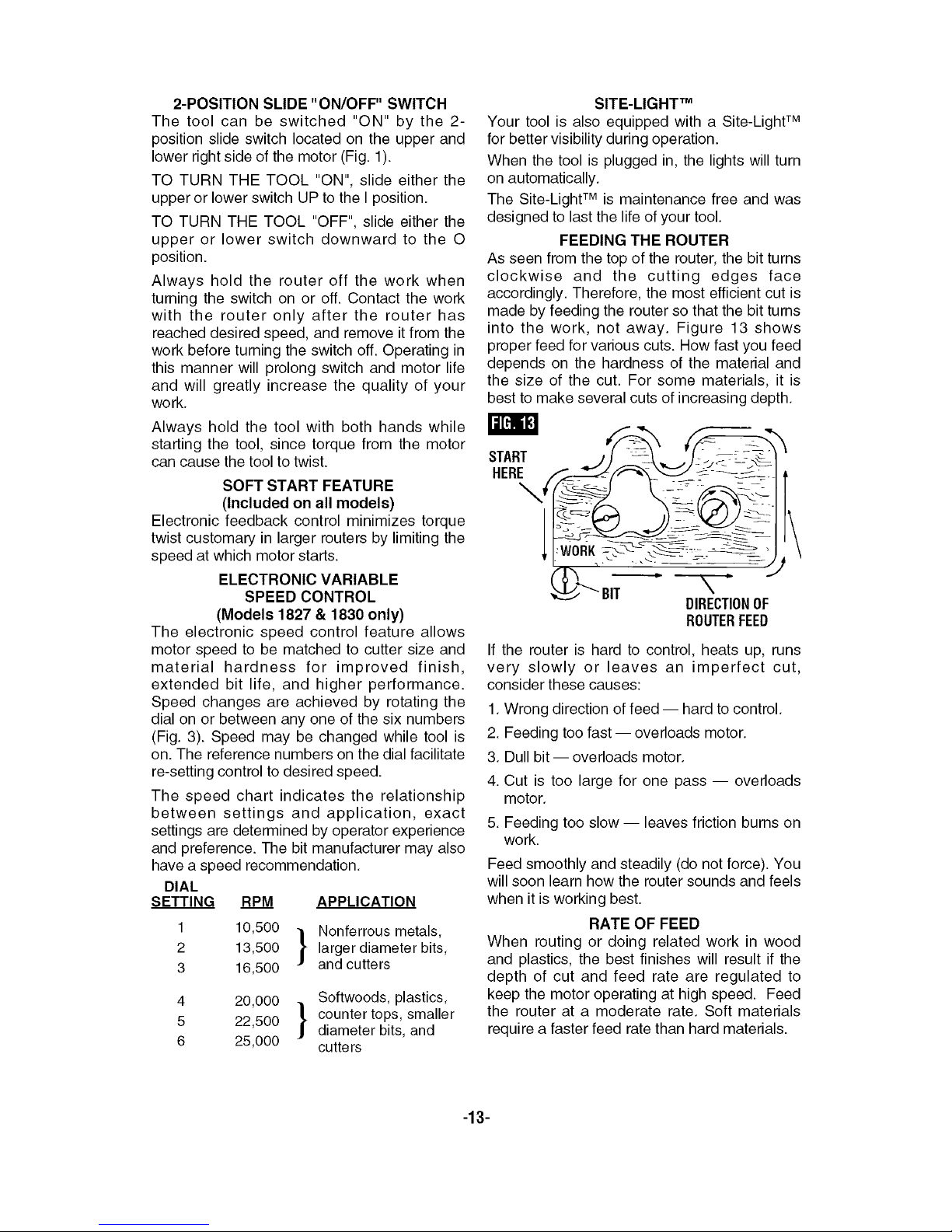
FEEDING THE ROUTER
As seen from the top of the router, the bit turns
clockwise and the cutting edges face
accordingly. Therefore, the most efficient cut is
made by feeding the router so that the bit turns
into the work, not away. Figure 13 shows
proper feed for various cuts. How fast you feed
depends on the hardness of the material and
the size of the cut. For some materials, it is
best to make several cuts of increasing depth.
START.
HERE f_----_--_-_ "_-_----J_-_--_'_ *
DIRECTIONOF
ROUTERFEED
If the router is hard to control, heats up, runs
very slowly or leaves an imperfect cut,
consider these causes:
1. Wrong direction of feed -- hard to control.
2. Feeding too fast-- overloads motor.
3. Dull bit-- overloads motor.
4. Cut is too large for one pass -- overloads
motor.
5. Feeding too slow -- leaves friction burns on
work.
Feed smoothly and steadily (do not force). You
will soon learn how the router sounds and feels
when it is working best.
RATE OF FEED
When routing or doing related work in wood
and plastics, the best finishes will result if the
depth of cut and feed rate are regulated to
keep the motor operating at high speed. Feed
the router at a moderate rate. Soft materials
require a faster feed rate than hard materials.
-13-
The router may stall if improperly used or
overloaded. Reduce the feed rate to prevent
possible damage to the tool.
Always be sure the collet nut is tightened
securely before use.
Always use router bits with the shortest
cutting length necessary to produce the
desired cut. This will minimize router bit run-
out and chatter.
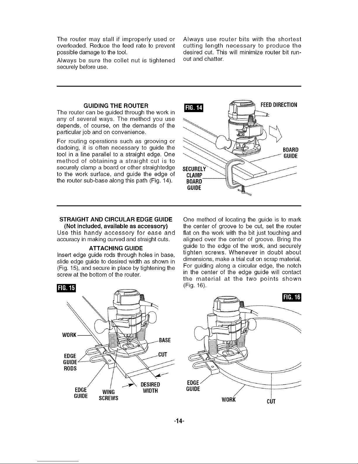
GUIDING THE ROUTER
The router can be guided through the work in
any of several ways. The method you use
depends, of course, on the demands of the
particular job and on convenience.
For routing operations such as grooving or
dadoing, it is often necessary to guide the
tool in a line parallel to a straight edge. One
method of obtaining a straight cut is to
securely clamp a board or other straightedge
to the work surface, and guide the edge of
the router sub-base along this path (Fig. 14).
FEEDDIRECTION
BOARD
GUIDE
SECURED
CLAMP
BOARD
GUIDE
STRAIGHT AND CIRCULAR EDGE GUIDE
(Not included, available as accessory)
Use this handy accessory for ease and
accuracy in making curved and straight cuts.
ATTACHING GUIDE
Insert edge guide rods through holes in base,
slide edge guide to desired width as shown in
(Fig. 15), and secure in place by tightening the
screw at the bottom of the router.
One method of locating the guide is to mark
the center of groove to be cut, set the router
flat on the work with the bit just touching and
aligned over the center of groove. Bring the
guide to the edge of the work, and securely
tighten screws. Whenever in doubt about
dimensions, make a trial cut on scrap material.
For guiding along a circular edge, the notch
in the center of the edge guide will contact
the material at the two points shown
(Fig. 16).
EDGE
GUIDE
RODS
EDGE
GUIDE
WING
SCREWS
DESIRED
WIDTH
GUIDE
WORK
CUT
-14-
_l[_llifi
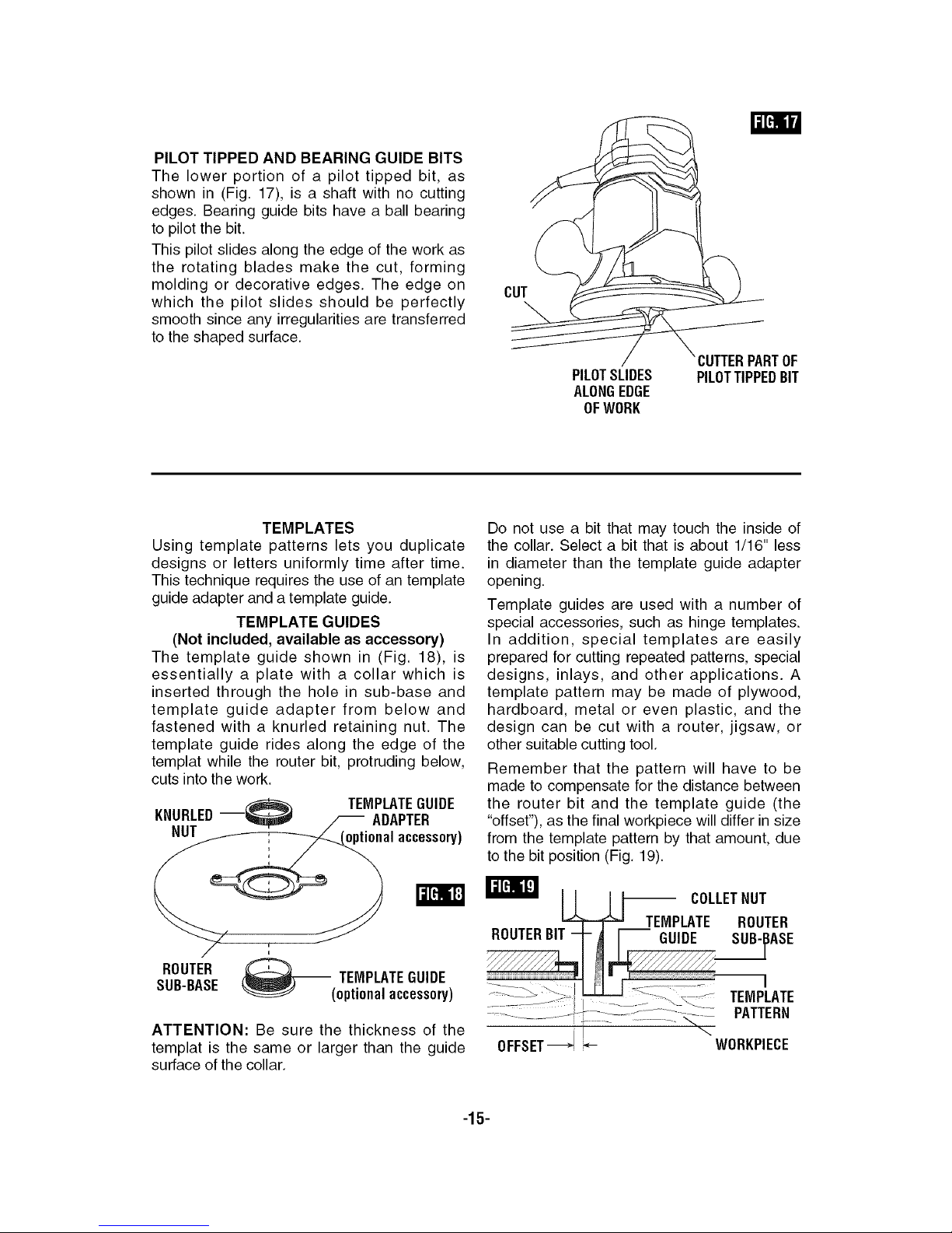
PILOT TIPPED AND BEARING GUIDE BITS
The lower portion of a pilot tipped bit, as
shown in (Fig. 17), is a shaft with no cutting
edges. Bearing guide bits have a ball bearing
to pilot the bit.
This pilot slides along the edge of the work as
the rotating blades make the cut, forming
molding or decorative edges. The edge on
which the pilot slides should be perfectly
smooth since any irregularities are transferred
to the shaped surface.
CUT
PILOTSLIDES
ALONGEDGE
OFWORK
CUTTERPARTOF
PILOTTIPPEDBIT
TEMPLATES
Using template patterns lets you duplicate
designs or letters uniformly time after time.
This technique requires the use of an template
guide adapter and a template guide.
TEMPLATE GUIDES
(Not included, available as accessory)
The template guide shown in (Fig. 18), is
essentially a plate with a collar which is
inserted through the hole in sub-base and
template guide adapter from below and
fastened with a knurled retaining nut. The
template guide rides along the edge of the
templat while the router bit, protruding below,
cuts into the work.
TEMPLATEGUIDE
KNURLED--_ _ ADAPTER
al acce_
ROUTER ,_-- TEMPLATEGUIDE
SUB-BASE _ (optional accessory)
ATTENTION: Be sure the thickness of the
templat is the same or larger than the guide
surface of the collar.
Do not use a bit that may touch the inside of
the collar. Select a bit that is about 1/16" less
in diameter than the template guide adapter
opening.
Template guides are used with a number of
special accessories, such as hinge templates.
In addition, special templates are easily
prepared for cutting repeated patterns, special
designs, inlays, and other applications. A
template pattern may be made of plywood,
hardboard, metal or even plastic, and the
design can be cut with a router, jigsaw, or
other suitable cutting tool.
Remember that the pattern will have to be
made to compensate for the distance between
the router bit and the template guide (the
"offset"), as the final workpiece will differ in size
from the template pattern by that amount, due
to the bit position (Fig. 19).
rmm II II C0LLETNUT
TEMPLATE ROUTER
ROUTERBIT -_- _ r - GUIDE SUB-I_ASE
PATTERN
OFFSET_i I-. WORKPIECE
-15-
ROUTER DUST COLLECTION
There are two optional dust extraction hood
accessories. Each dust extraction hood is
sized to accept 35mm vacuum hoses. Each
accessory pack includes an adapter that will
connect the hood to 1-1/4" and 1-1/2" vacuum
hoses.
__J_ Read and understand these
instructions and tool
manual for use of these accessories.
Do not reach in area of the bit while the
router is ON or plugged in.
To avoid entangling hoses,
do not use this dust
extraction hood at the same time as any
other dust extraction hood.
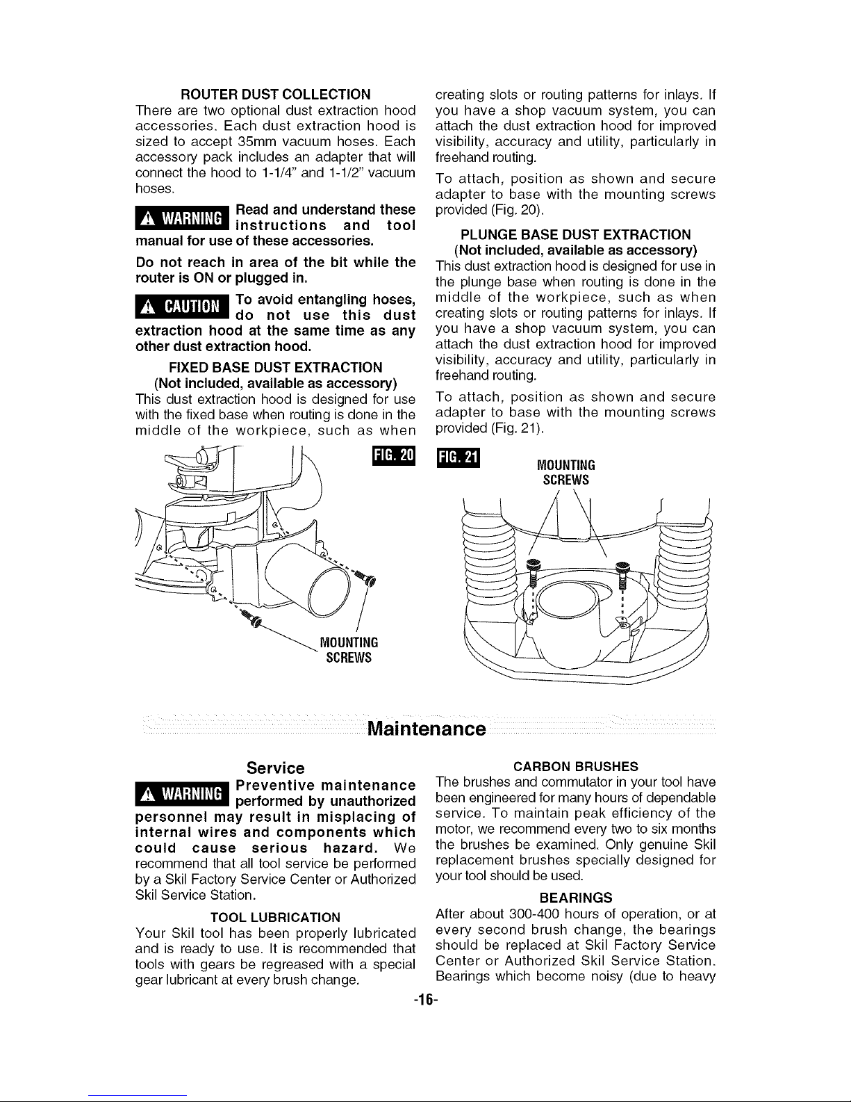
FIXED BASE DUST EXTRACTION
(Not included, available as accessory)
This dust extraction hood is designed for use
with the fixed base when routing is clone in the
middle of the workpiece, such as when
creating slots or routing patterns for inlays. If
you have a shop vacuum system, you can
attach the dust extraction hood for improved
visibility, accuracy and utility, particularly in
freehand routing.
To attach, position as shown and secure
adapter to base with the mounting screws
provided (Fig. 20).
PLUNGE BASE DUST EXTRACTION
(Not included, available as accessory)
This dust extraction hood is designed for use in
the plunge base when routing is done in the
middle of the workpiece, such as when
creating slots or routing patterns for inlays. If
you have a shop vacuum system, you can
attach the dust extraction hood for improved
visibility, accuracy and utility, particularly in
freehand routing.
To attach, position as shown and secure
adapter to base with the mounting screws
provided (Fig. 21).
i_l[_i,,[I]
MOUNTING
SCREWS
MOUNTING
SCREWS
Service
_ reventive maintenance
performed by unauthorized
personnel may result in misplacing of
internal wires and components which
could cause serious hazard, We
recommend that all tool service be performed
by a Skil Factory Service Center or Authorized
Skil Service Station.
TOOL LUBRICATION
Your Skil tool has been properly lubricated
and is ready to use. It is recommended that
tools with gears be regreased with a special
gear lubricant at every brush change.
CARBON BRUSHES
The brushes and commutator in your tool have
been engineered for many hours of dependable
service. To maintain peak efficiency of the
motor, we recommend every two to six months
the brushes be examined. Only genuine Skil
replacement brushes specially designed for
your tool should be used.
BEARINGS
After about 300-400 hours of operation, or at
every second brush change, the bearings
should be replaced at Skil Factory Service
Center or Authorized Skil Service Station.
Bearings which become noisy (clue to heaw
-16-
load or very abrasive material cutting) should
be replaced at once to avoid overheating or
motor failure.
Cleaning
To avoid accidents always
disconnect the tool from
the power supply before cleaning or
performing any maintenance. The tool may
be cleaned most effectively with compressed
dry air. Always wear safety goggles when
cleaning tools with compressed air.
Ventilation openings and switch levers must
be kept clean and free of foreign matter. Do
not attempt to clean by inserting pointed
objects through openings.
_ Certain cleaning agents
and solvents damage
plastic parts. Some of these are: gasoline,
carbon tetrachloride, chlorinated cleaning
solvents, ammonia and household detergents
that contain ammonia,
If an extension cord is
necessary, a cord with
adequate size conductors that is capable of
carrying the current necessary for your tool
must be used. This will prevent excessive
voltage drop, loss of power or overheating.
Grounded tools must use 3-wire extension
cords that have 3-prong plugs and receptacles.
NOTE: The smaller the gauge number, the
heavier the cord.
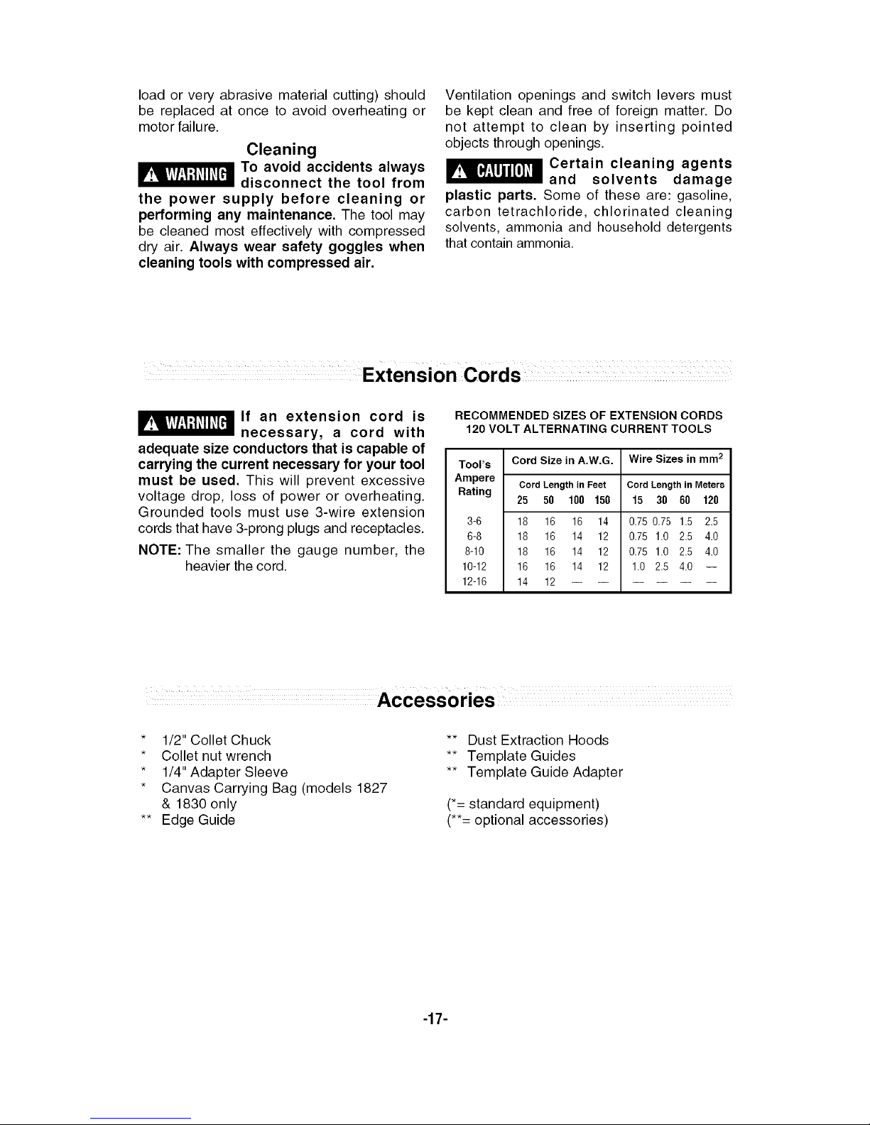
RECOMMENDED SIZES OF EXTENSION CORDS
120 VOLT ALTERNATING CURRENT TOOLS
Tool's Cord Size in A.W.G. Wire Sizes in mm 2
Ampere
Rating
3-6
6-8
8-10
10-12
12-16
CordLengthin Feet
25 50 100 150
18 16 16 14
18 16 14 12
18 16 14 12
16 16 14 12
14 12
CordLengthin Meter8
15 30 60 120
075 075 1.5 2.5
0.75 1.0 2.5 4.0
0.75 1.0 2.5 4.0
1.0 2.5 4.0 --
* 1/2" Collet Chuck
* Collet nut wrench
* 1/4" Adapter Sleeve
* Canvas Carrying Bag (models 1827
& 1830 only
** Edge Guide
** Dust Extraction Hoods
** Template Guides
** Template Guide Adapter
(*= standard equipment)
(**= optional accessories)
-17-
 Loading...