


SI-TEX MARINE ELECTRONICS INC
#800 - 11001 Roosevelt Blvd
St. Petersburg, Florida 33716
Phone (727) 576-5995
INSTALLATION and OPERATION MANUAL
SI-TEX SP-70 AND SP-80 AUTOPILOTS
SI-TEX SP-80 AUTOPILOT
SI-TEX SP-70 AUTOPILOT
P/N 29010049 V1.2 |
2 |

WARNING
This Autopilot will automatically steer your vessel, however, it is only an aid to navigation. Its performance can be affected by many factors including equipment failure, environmental conditions and improper handling or use. This system does not reduce your responsibility for the control of the vessel when underway. You must always be in a position to monitor the course, supervise the Autopilot, and resume manual control if the need to do so arises.
Whenever underway, your vessel must be under the control of a qualified and alert person.
|
|
|
|
P/N 29010049 V1.2 |
3 |
SI-TEX SP-70 and SP-80 Autopilot Manual
Owner’s Manual for Installation and Operation
Part Number: 29010049
SI-TEX MARINE ELECTRONICS INC
#800 – 11001 Roosevelt Blvd
St. Petersburg, FL 33716
Telephone: (727) 576-5995
P/N 29010049 V1.2 |
4 |
TABLE OF CONTENTS |
|
PRODUCT DESCRIPTION ..................................................................................................................................................7 |
|
SP-70/SP-80 System layout |
8 |
SI-TEX SP-70/SP-80 PARTS LIST .......................................................................................................................................9 |
|
INSTALLATION INSTRUCTIONS ..................................................................................................................................13 |
|
SI-TEX MARINE REVERSING PUMP |
13 |
Tools And Materials Required To Install Pump |
14 |
Hydraulic Connections For Two-Line Steering Systems |
17 |
Hydraulic Connections For Three-Line Steering Systems |
18 |
Technical Specifications |
19 |
Specifications Common To Both Pumps |
19 |
INSTALLATION INSTRUCTIONS ..................................................................................................................................21 |
|
Planning |
21 |
Tools |
22 |
Clip Installation |
23 |
Power Cable Installation |
24 |
Fluxgate Compass Installation |
24 |
Rotary Rudder Feedback Installation |
25 |
Attaching the Rudder Feedback Linkage. |
27 |
Outboard Feedback Installation |
31 |
Wiring the Processor |
35 |
Mounting the Processor |
41 |
Setting Slow Speed Rudder Response |
60 |
Turns and Changing Course |
61 |
Setting Fast Speed Rudder & CounterRudder Response. |
63 |
Fast Speed Turns and Course Changes |
64 |
Adjusting Your Digital Rudder Angle Indicator (RAI) |
66 |
Using Your Navigation Interface |
67 |
The Navigation Interface |
68 |
NMEA 0183 |
68 |
ADJUSTMENT COMMANDS............................................................................................................................................73 |
|
USER CODES FOR THE SI-TEX SP-70 & SP-80 ...........................................................................................................74 |
|
PROBLEMS WITHOUT AN ERROR CODE..................................................................................................................77 |
|
APPENDIX A .........................................................................................................................................................................78 |
|
Connections to 4 and 5 Wire Motors |
78 |
APPENDIX A |
79 |
APPENDIX B..........................................................................................................................................................................80 |
|
Connections to Solenoid Valves |
80 |
P/N 29010049 V1.2 |
5 |
APPENDIX C .........................................................................................................................................................................81 |
|
Connecting a Second Location or Second Station Options |
81 |
Second Location Kit |
81 |
Second Station Kit |
82 |
APPENDIX D .........................................................................................................................................................................84 |
|
Connecting a Rudder Angle Indicator |
84 |
APPENDIX E..........................................................................................................................................................................85 |
|
Connecting the NMEA 0183 Heading Output |
85 |
CERTIFICATE OF LIMITED WARRANTY..................................................................................................................87 |
|
P/N 29010049 V1.2 |
6 |
PRODUCT DESCRIPTION
SI-TEX SP-70 or SP-80 Autopilots are reliable, accurate and easy to use aids to navigation. They feature four operating modes, watertight design, and built-in navigation interface.
The 4 operating modes are:
•STANDBY MODE allows manual steering while displaying compass information.
•POWER STEERING MODE features push button steering control, and displays compass or rudder information.
•PILOT MODE steers to a constant heading.
•NAV MODE steers along a course line when the SP-70 or SP-80 is connected to an appropriate navigation device.
In both PILOT and NAV Mode, pressing the Red or Green Key allows use of the Dodge/Course-change feature.
To steer a constant heading, the SP-70 or SP-80 compares compass heading information with the course heading that is entered into memory. If the vessel is not on the correct heading, the Autopilot calculates the rudder position that will bring the vessel onto the correct heading. The Autopilot uses a drive unit to move the rudder. Information from the Rotary Feedback or Outboard Feedback is used to calculate new rudder positions and to verify that the steering system has followed the Autopilot commands.
When steering along a course line, both Autopilots use information from the compass to monitor the heading. They also use position information received in NMEA 0183 format from LORAN, GPS, or plotter. Using both of these inputs, the SP-70/SP-80 calculates a course to steer and keeps the vessel on the course line.
The SP-70/SP-80 contains a program called Ghost Rudder. Should the Rudder Feedback fail, the Autopilot will use its memory of the rudder movement to calculate new rudder positions. The Ghost Rudder program will not allow the Autopilot to steer as well as it can with the Rudder Feedback. It will allow the Autopilot to be used until repairs can be made to the Rudder Feedback.
The design of the SP-70/SP-80 includes many circuit protection devices such as; reverse power connection protection, output circuitry overload protection, protection against overheating, protection against computer failure or program error.
SPECIFICATIONS
Voltage: 10VDC - 40 VDC
Steering Outputs: 20 Amperes Maximum
Sizes |
L X W X H |
SP-70 Control: |
2.75 x 5.13 x 1.0 in. |
|
(7.0 x 13.3 x 2.5 cm.) |
SP-80 Control: |
6.0 x 3.1 x 1.0 in |
|
(15.4 x 7.9 x 2.5 cm) |
Processor: |
6.3 X 15 X 2.7 in. |
|
(16.0 x 38.1 x 6.9 cm.) |
Compass: |
5.6 x 4.2 x 3.4 in. |
|
(14.2 x 10.7 x 7.6 cm) |
Pump: |
4.8 x 7.5 x 4 in. |
cm.) |
(12.2 x 19.0 x 10.2 |
|
P/N 29010049 V1.2 |
7 |
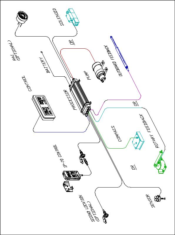
SP-70/SP-80 System layout |
P/N 29010049 V1.2 |
8 |

SI-TEX SP-70/SP-80 PARTS LIST
Parts are not drawn to any scale.
Si-Tex Processor: Part Number 30080003. Used on both SP-70 and SP-80 Autopilot packages.
FOR SP-70 AUTOPILOT PACKAGES
SP-70 Control Unit. Part Number 20080009. This part includes a curly cord wired to the Control Unit.
SP-70 Control Unit Clip and Spacer. Part
Number 65610010.
FOR SP-80 AUTOPILOT PACKAGES
SP-80 Control Unit and Mounting Bracket. Part Number 20080011.
This part includes a 25 foot (7.7 meter) cable wired to the Control Unit.
P/N 29010049 V1.2 |
9 |
SP-70/SP-80 Fluxgate Compass. Part Number 20320003. This part includes 40 feet (12.2 m) of cable wired to the compass.
In this group, one part OR the other part will be included:
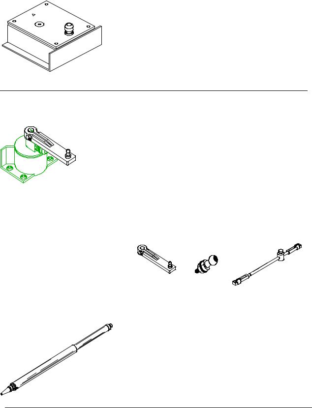
Rotary Rudder Feedback: Part Number 20330008. This part includes 50 feet (15.2 m) of cable wired to the Rudder Feedback. This part will always come with:
Rotary Rudder Feedback Linkage Kit.
Part Number 20330007
OR
Outboard Feedback: Part Number 20330002. This part includes 30 feet (9.1 m) of cable wired to the Rudder Feedback.
P/N 29010049 V1.2 |
10 |
Also included but not drawn:
•Power Cable: Seven and a half feet (2.3 m) of cable provided for connection of Processor and breaker.
•Accessory Kit: Contains a small screwdriver, extra terminal sockets and gland.
•Control Unit Interconnection Cable (SP-70 systems only): 10 feet (3.05 m) of cable with a receptacle and cap on one end. Labelled as cable one.
•Si-Tex SP-70 and SP-80 Autopilot Manual. Part Number 29010049.
Adjustable Reversing Pump. Part Number 20810016 (12VDC/18CI), 20810031 (24VDC/18CI), 20810018 (12V/30CI) and 20810035 (24V/30CI). 18CI pumps are for installations where the steering ram size is from 7 in3 (115 cm3) up to 18 in3 (295 cm3). 30CI pumps are for installations where the steering ram size is from 15 in3 (245cm3) up to 30 in3 (490 cm3).
P/N 29010049 V1.2 |
11 |
This page is intentionally blank.
P/N 29010049 V1.2 |
12 |

INSTALLATION INSTRUCTIONS
SI-TEX MARINE REVERSING PUMP
Part Nos. 20810016, 20810031, 20810018 & 20810035
GENERAL:
The reversing pump consists of a hydraulic pump and a motor. The pump is a piston type, driven by a reversing permanent magnet motor. The pump is designed in such a way that it will keep oil from returning through the pump when is not running or correcting. There is also a bleed-to tank to allow the use of unbalanced cylinders. The pump is compatible with all hydraulic steering systems including pressurized steering systems such as Hynautic.
SPILL VALVE
ADJUSTMENT
To adjust flow rate, loosen pump housing screws and turn pump housing. Clockwise will decrease flow rate, anti-clockwise to increase flow rate.
Part Nos. 20810016(12V) & 20810031(24V) 18CI Pumps
The pumps above can be ordered with a 12VDC or 24VDC motor and have an adjustable flow rate that will deliver from 36 in3 to 73 in3 (600 cm3 – 1200 cm3) per minute of oil at 500 PSI (3,440 kPa) (34 Bar). It is suitable for rams with displacements ranging from 7 in3 (115 cm3) to 18 in3 (295 cm3)) displacement.
Part No. 20810018(12V) and 20810035(24V) 30CI Pumps
The pumps above can be ordered with a 12VDC or 24VDC motor and have an adjustable flow rate that will deliver from 61 in3 to 122 in3 (1000 cm3 – 2000 cm3) per minute of oil at 500 PSI (3,440 kPa) (34 Bar). It is suitable for rams with displacements ranging from 15 in3 (246 cm3) to 30 in3 (495 cm3) displacement.
P/N 29010049 V1.2 |
13 |

***** IMPORTANT *****
If the system you purchased includes a reversing motor pumpset, it is important that you apply and install this unit correctly. To ensure that you get the most from your purchase, read this installation and instruction manual carefully. By following the step-by-step procedure and using only basic tools and materials, you will find the installation easy to do.
Caution
This Pump is not waterproof and is therefore not warranted against water damage. This Pump is not warranted against damage caused by improper installation.
If you are installing this pump on a Capilano or Syten steering system, you probably have a 3-line steering system. Read the 3-line steering installation instructions carefully.
Tools And Materials Required To Install Pump
1)Basic Tool Kit
2)Pipe Cutter
3)Funnel with Filter (a coffee filter will do)
4)3/8" Electrical Drill
5)2 gallon (9 L.) bucket (to catch excess oil).
6)Rags or Paper Towels
7)Pipe Fittings (check with steering gear manufacturer for type & size)1
8)Tubing (check with steering gear manufacturer for type and size)1
9)Hydraulic Oil (check with steering gear manufacturer for type)1
10)Teflon based thread sealer (such as LOCTITE™ P.S.T.)
11)Miscellaneous Hardware (for mounting pump and securing lines)
1. Consult with your steering system manufacturer to get detailed information about factory authorized materials. Failure to do so could void your warranty.
P/N 29010049 V1.2 |
14 |
Planning
Installation of the pump consists of:
•Finding a mounting location for the pump
•Partially draining the steering system
•Mounting and connecting the pump to the existing steering lines
•Filling and bleeding the steering system.
A suitable mounting location for the pump MUST:
•Be dry
•Be lower than at least one of the helm pumps in the steering system
•Provide a solid mounting base
•Be at least 4 feet (3.1 m) from the vessel’s compass.
A mounting location for the pump SHOULD:
•Provide easy access to the pump
•Provide an easy connection point to the steering system
•Minimize the length of the pump hoses
•Minimize the length of the wires to the motor.
A typical mounting location would be in the engine compartment or the steering console.
The pump can be mounted in any orientation except with Port C facing downward. If Port C is facing downward then air will not be able to rise out of the pump and the pump will not have a supply of oil.
There are two ways to connect the pump to the steering system. The first is to leave the system completely filled and be careful not to spill hydraulic fluid. The second is to drain the system of fluid completely before cutting or opening any lines.
If you follow the first method, remember that when you disconnect or cut the steering lines, there will be a constant slow discharge of oil due to gravity draining the system. Have a container ready to catch all excess oil. Do not reuse any oil reclaimed from your system.
Draining your System
If you wish to follow the second method and drain the system, use the following simple procedure.
1.Have a large container, about 2 gallons, ready.
2.Disconnect the delivery lines at a low point, usually where the lines connect to the steering cylinder.
3.Turn the wheel of the highest helm pump in both directions until no more fluid comes out of the lines.
4.Repeat the previous step on each lower helm pump in turn.
Types of Steering Systems
There are two general types of steering systems, two-line systems, and three-line systems. The pump connection to the steering system is different for each type. Separate instructions are supplied for both types of steering systems.
You have a three-line system if the helm pump is a Capilano Model 250 or 275 (Made by Teleflex), or if there is a Uniflow valve mounted close to the steering cylinder.
P/N 29010049 V1.2 |
15 |

You have a two-line system if you do not have the above components in your system.
CAUTION
CLEANLINESS must be maintained while making hydraulic connections. Contamination introduced into the steering system fluid can cause steering components to malfunction, possibly resulting in a loss of steering.
Before beginning to connect the pump to the steering system, review the following installation hints:
•Cap or cover the ends of hoses with a clean rag before pushing them between bulkheads.
•Wipe copper filings off freshly cut and reamed copper tube. Do not blow the filings off.
•Teflon based thread sealer, such as 'LOCTITE™ P.S.T.' must be used on all male pipe threads. Do not place thread sealer on the first two threads. Do not use a tape-type thread sealer. These can shred and enter the steering system fluid.
Do not place thread sealer on female pipe threads.
•When tightening fittings into the pump lockvalve, hold the lockvalve, not the motor. That way, the lockvalve will not twist out of alignment with the rest of the pump.
•Connection of the pump lines is most easily made at existing breaks in the steering system lines. For example: valves, t-joints and other fittings.
CAUTION
Opening your hydraulic steering system will introduce air into your steering system. This air will be expelled if the steering system is bled properly. After you refill your system and during the "Set-up Routine", your autopilot can be used for bleeding the air. Ensure that you follow the Compensating Line installation instructions very carefully as all air is expelled through this line when bleeding your system. If the Compensating Line does not prime properly and allow fluid to get to the autopilot pump, the pump will not perform properly. The Compensating Line does not have to be a highpressure hose. In fact, even a clear hose can be used allowing for easy visual confirmation of proper Compensating Line operation.
P/N 29010049 V1.2 |
16 |

Hydraulic Connections For Two-Line Steering Systems
A simple schematic of the pump installation is shown below.
2 Line Steering System Installation
Delivery Lines:
Ports A and B in the diagram above are the input/output ports of the pump and must be connected to the steering lines coming from the steering cylinder. It does not matter which pump port is connected to which steering line.
Compensating Line:
In the above diagram Port C is the compensating or bleed line, and must be connected to the steering system's reservoir. This connection can be made at: a helm pump; remote reservoir (if there is one); the compensating line connecting two helm pumps; or the compensating line connecting a helm pump to the remote reservoir. If the connection is being made directly to the helm pump, ensure that the bleed line is connected to the LOWER helm bleed port.
The compensating line MUST have a gradual rise from the pump, to the connection, to the steering system. This allows air to rise out of the pump, ensuring a constant supply of oil to the pump.
INSTALLATION OF SHUT-OFF VALVES RECOMMENDED
P/N 29010049 V1.2 |
17 |
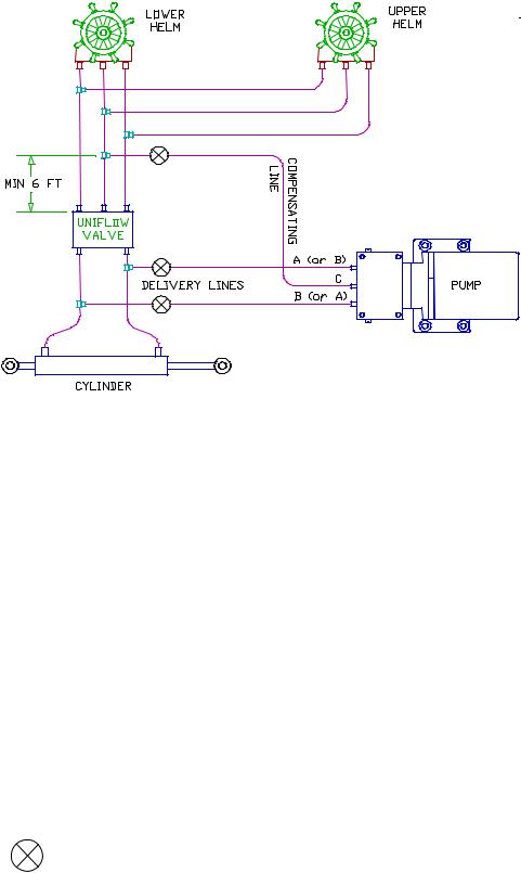
Hydraulic Connections For Three-Line Steering Systems
A simple schematic of the pump installation is shown below.
3 Line Steering System Installation
Delivery Lines:
In the above diagram, Ports A and B are the input/output ports of the pump and must be connected to the steering lines between the steering cylinder and the Uniflow valve. The simplest method of doing this is to install a tee in each of the cylinder ports of the Uniflow valve itself and connect to these tees. It does not matter which pump port is connected to which steering line.
Compensating Line:
Port C is the compensating or bleed line and must be connected to the steering systems’ reservoir. This connection can be made at a helm pump; a remote reservoir (if there is one); the return line connecting two helm pumps; or the return line between a pump and the Uniflow valve. If the connection is being made directly to the helm pump, ensure that the bleed line is connected to the LOWEST bleed port of the pump.
The connection MUST be at least six feet (1.83 m) from the Uniflow valve as shown above. If the connection is too close to the Uniflow valve, the manual steering system may not work well.
The compensating line MUST have a gradual rise from the pump, to the connection, to the steering system. This allows air to rise out of the pump, ensuring a constant supply of oil to the pump.
INSTALLATION OF SHUT-OFF VALVES RECOMMENDED
P/N 29010049 V1.2 |
18 |
Re-Fill And Bleed
After you have installed your Pump, refill and bleed your manual steering system according to the manufacturer's directions. Any air, which is in the pump, will be expelled during the Set-up Routine.
|
Technical Specifications |
|
|
|
Part Number: |
20810016 |
20810031 |
20810018 |
20810035 |
Model Number: |
18CI |
18CI |
30CI |
30CI |
Operating Voltage: |
12VDC |
24VDC |
12VDC |
24VDC |
Max Displacement @ 200PSI: |
73 in3 |
73 in3 |
122 in3 |
122 in3 |
Current @ 200 PSI: |
4.5 Amps |
3.0 Amps |
6.0 Amps |
3.0 Amps |
Max Pressure: |
800 PSI |
800 PSI |
500PSI |
500PSI |
Specifications Common To Both Pumps |
|
|||
Port Sizes: |
- 3/8 inch compression fittings supplied |
|
||
Displacement (18CI): |
- Adjustable, from 26in3 (600cm3) to 73in3 (1200cm3) |
|||
Displacement (30CI): |
- Adjustable, from 61in3 (1000cm3) to 122in3 (2000cm3) |
|||
Min Stall Pressure: |
- 1200 PSI (84.0 Bar) (8,268 kPa) |
|
||
Oil Type: |
- Any approved hydraulic steering fluid |
|
||
Operating Temperature: |
- 0 to 50 Degrees Celsius (32 to 122 Fahrenheit) |
|||
Lockvalve: |
- Yes |
|
|
|
Lockvalve Leakage: |
- Negligible |
|
|
|
Unbalanced Cylinder: |
- Yes, up to 3/4 (1.9cm) diameter rod |
|
||
Weight: |
- 5.0 lbs (2.27 kg) including wire |
|
||
Size: |
- 10 inches x 3.75 inches x 4.75 inches |
|
||
Size (metric): |
- 254mm x 95mm x 121mm |
|
|
|
Shaft Seal: |
- 100 PSI (6.89 Bar) (689 kPa) minimum |
|
||
P/N 29010049 V1.2 |
19 |

Connection between SP-70 Control Unit and Receptacle on Cable Number 1
SP-80 Control Unit and cable going to Si-Tex Processor
P/N 29010049 V1.2 |
20 |
INSTALLATION INSTRUCTIONS
SP-70 and SP-80 AUTOPILOTS
Planning
Caution
Using ordinary electric tools near water is very dangerous. To minimize the dangers of electric shock and personal injury, we recommend using cordless rechargeable tools or hand tools.
If you are going to use a sealant when flush mounting the SP-80 Control Head, be careful to not cover the small square hole in the middle of the bottom side. This hole must vent to atmosphere.
Do not mount the Processor near heat sources, such as heat radiators, or over engines. If you can, mount the Processor so that the cooling fins are vertical.
Processor Location
Allow at least a foot or 30 cm of clearance on either end of the Processor in the space where it is to be located.
In choosing a location for your SI-TEX SP-70/SP-80, remember that the Control Unit Interconnection Cable or Number 1 Cable, and the cable from the Compass to the Processor should not be cut or lengthened. Excess cable may be loosely coiled behind a panel.
Number 1 Cable from the SP-70 Control Unit Receptacle to the Processor is 10 feet long (3.05 metres). Number 1 cable from the SP80 Control Unit to Processor is 25 feet long (7.7 metres).
The cable from the Compass to the Processor is 40 feet long (12.2 metres).
You will want to have the Control unit near the steering station you use the most. On SP70’s try to position the Receptacle so that the curly cord will also reach other convenient locations such as the place that you use when docking your vessel.
Power Connection
There is a 7.5 foot (2.3 metre) power cable included with your SI-TEX SP-70/SP-80. We recommend that you do not lengthen this cable.
If you must extend the cable:
•Use the smallest extension length possible.
•Use no less than 10 A.W.G. (6mm2) conductor. Splice and solder the joints.
•The extension must be less than 10 feet (3 metres).
•Make the joints watertight by using heatshrink tubing and silicon, or some other watertight covering.
P/N 29010049 V1.2 |
21 |
Grounding
The Power Cable also contains a grounding wire. Connecting this wire to a proper ground (*see below) may reduce static on radios and improve LORAN reception.
Many different grounding connections could be used:
1.If you have a small vessel, the negative battery post can be used.
2.If you have several electronic instruments, each could be individually attached to the battery post. Do not connect one instrument to another instrument and then to the post.
3.If you have a ground plane for a radio on your boat, connect the ground wire to that ground plane.
*A proper ground connection point must be at the same voltage potential as battery negative. Any voltage difference between battery negative and the ground point may indicate a problem and the ground wire should not be used. Ensure that connection wires are as short as possible and that connections are clean.
Compass Location
When choosing a location for the Compass, try to locate it as close as possible to the most stable spot on your boat. Usually this spot will be close to the water line level, in the middle of the boat and two-thirds towards the stern from the bow.
Do not install your Compass near wires or devices carrying large electric currents such as battery chargers, electric pumps, motors or televisions.
Do not mount your Compass near any iron or steel objects.
Tools
You will need the following tools to install your SI-TEX Autopilot:
SCREWDRIVER: One Phillips and one medium slot screwdriver
WIRE CUTTERS: A pair of ordinary wire cutters suitable for general work around your house.
DRILL and a selection of DRILL BITS
SMALL ADJUSTABLE WRENCH
If you purchased a SP-70 or SP-80 with a Rotary Rudder Feedback you may need one stainless steel band clamp which is more than large enough to fit around your rudder post.
You may also wish to have a supply of tie wraps for securing cable lengths and tools specific to your own boat.
P/N 29010049 V1.2 |
22 |
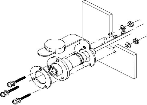
SP-70 Receptacle Installation
The Receptacle is attached to the Number 1 cable. The diagram to the right shows the Receptacle mounted in a panel.
Mount the receptacle near your normal steering position.
The curly cord on the Control Unit lets you move about 5 feet away from the Receptacle.
A stainless steel ring is placed between the bolt heads and the receptacle flange. Do not attempt to seal the
receptacle by overtightening the bolts
as the ring will deform the receptacle and interfere with plug insertion. A proper
caulking compound
or sealant should be used instead. The three bolts should only be tightened enough to compress the lock-washers, no more. As the plug has a tight seal, and insertion into the receptacle may be stiff, a lubricant has been included in your package.
Hole sizes:
Hole for receptacle: 0.825 inches or 21 mm in diameter.
Use the barrel of the Receptacle to mark holes for the flange.
Holes in the flange are for a number 6 (3mm) screw. You may wish to vary this size depending upon the panel material.
Clip Installation
The Clip is used for mounting the Control Unit. The Clip is mounted with two number 10 (5mm) screws or bolts.
The usual mounting location is on the dashboard within easy reach when you are steering your vessel.
P/N 29010049 V1.2 |
23 |

Power Cable Installation
The Power Cable is labelled with a "5". Connect the Power Cable to a breaker capable of supplying twenty Amperes.
CAUTION
Keep the breaker turned off or do not connect the cable to the breaker.
Use the white wire for battery positive from the breaker. Use the black wire for battery negative. The green wire is a grounding wire.
Extending the cable is not recommended. If you must extend it, see page 23 for guidelines on proper extension techniques.
Route the supplied Cable to the Processor location.
Fluxgate Compass Installation
Fluxgate Compass
The fluxgate compass must be correctly positioned or it will not work.
To correctly position the Fluxgate Compass, mount it so that the surface with the cable gland is up. On the top surface there is an arrow labelled "bow". The arrow must point in the same direction as the bow of your boat. In cases where the compass is mounted on a side wall, the bow line arrow may be ± 90 degrees out of alignment. Remove the four top housing screws and rotate the housing ± 90 degrees. Warning: This unit comes from the factory watertight. Be careful with seals and “O” rings if you remove the housing.
Initially, mount your Fluxgate Compass using strong adhesive tape or some other temporary, non-marking fastener. Coil any excess cable at the Compass location rather than at the Processor. It may be necessary to relocate your compass after you have done the "Set-up Procedure".
P/N 29010049 V1.2 |
24 |
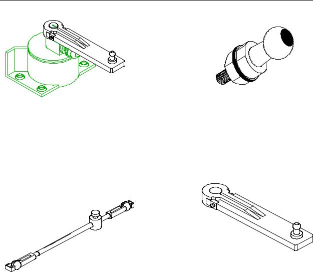
Rotary Rudder Feedback Installation
If you have purchased a SP-70 or SP-80 with an Outboard Feedback, please see the instructions titled, "Outboard Feedback".
Select the following parts from your SP-70 or SP-80 package:
RUDDER FEEDBACK |
BRASS BALL JOINT |
(INCLUDED WITH LINKAGE) |
LINKAGE |
RUDDER ARM |
You may also need:
•One stainless steel band clamp to hold the Rudder Arm to the rudder post.
•Four screws: #10 size (5 mm), suitable length.
Install the Rudder Feedback Assembly in the stern of the vessel, close to the rudder post. Place the Rudder Feedback so that it will be protected from objects which may shift position when your boat is moving.
P/N 29010049 V1.2 |
25 |
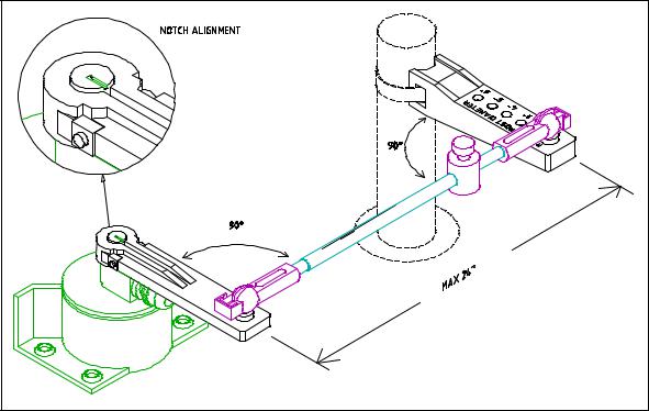
Mounting the Rudder Feedback
Rudder Feedback correctly installed to rudder post
In the diagram above notice that:
•the Rudder Feedback Arm is above the cable entry gland;
•the Linkage sockets are on the top of the ball joints. Do not hang the Linkage from the ball joints.
Mount the Rudder Feedback so that the Rudder Feedback Arm and the Rudder Arm:
•are at the same height and
•separated by less than 24 in. (60.9 cm) center to center, and
•each makes an angle of 90 degrees with the Linkage.
To correctly align the Rudder Feedback and the Rudder Arm, you may need to make a mounting base for the Rudder Feedback. Such a base must be firm. It should not flex when the vessel is moving.
Use the Rudder Feedback as a template to drill holes in the mounting surface. If you must drill new holes in the flange at the back of the Rudder Feedback, drill the Rudder Feedback flange first, and then use it as a template to drill holes in the surface.
Mount the Rudder Feedback using # 10 (5 mm) screws or bolts of suitable length.
P/N 29010049 V1.2 |
26 |

To Assemble the Rudder
Feedback Arm
Measure the approximate diameter of your rudder post in inches.
The Rudder Arm has several holes drilled through it. The holes are marked by numbers on the top surface of the arm.
Select the hole on the Rudder Arm marked by a number equal to the diameter of your rudder post measured in inches. (1 cm = 0.394 in.)
Bolt the Brass Ball Joint onto the Rudder Arm using the selected hole. The ball of the Brass Ball Joint must be on the same side of the Rudder Arm as the numbers. Tighten the nut and lock washer securely.
Attach the Rudder Post Arm to the rudder post using a stainless steel band clamp. The Brass Ball Joint must be on top. The Rudder Post Arm must be at the same height as the Rudder Follower.
The Rudder Post Arm must point straight ahead when the rudder is in the straight ahead steering position.
Attaching the Rudder Feedback
Linkage.
Move the rudder so it is in the straight ahead position.
Move the Rudder Feedback Arm so that the Arm is directly above the point where the cable enters the Rudder Feedback.
Loosen the adjustment block that keeps the two pieces of the Rudder Feedback Linkage from sliding.
Snap the Rudder Feedback Linkage onto the two Brass Balls. Make sure to close the small release clamps on each Plastic Socket.
With the Rudder Feedback Arm directly above the cable gland and the Rudder Arm pointing straight ahead, tighten the adjusting block.
Caution
Carefully watch the Linkage while you move the rudder through its full range of motion. The Rudder Feedback and the Rudder Feedback Linkage should move easily without binding. The moving parts must not contact any other objects. If there are any problems, fix them now.
Run the Rudder Feedback Cable from the Rudder Feedback to the space where the Processor will be located. Place the Cable so that it is protected from abrasion, stretching and cutting.
Turn to the section titled: "Wiring the Processor".
P/N 29010049 V1.2 |
27 |
 Loading...